
Heat Recovery Using PCM in Decentralised Façade Ventilation

Department of Building Physics and Renewable Energy, Faculty of Environmental, Geomatic and Energy Engineering, Kielce University of Technology, 25-314 Kielce, Poland
*
Author to whom correspondence should be addressed.
Energies 2023, 16(8), 3310; https://doi.org/10.3390/en16083310
Submission received: 19 February 2023
/
Revised: 27 March 2023
/
Accepted: 4 April 2023
/
Published: 7 April 2023
(This article belongs to the Section G2: Phase Change Materials for Energy Storage)
Abstract
:A study of heat recovery in a façade ventilation unit was carried out under laboratory conditions using a climate chamber that allowed stable outdoor and indoor conditions to be simulated. The unit, equipped with a reversible fan and a chamber for the heat exchanger, controlled by an automation control system, was designed to exchange air in the room by alternating supply and exhaust cycles of specific durations. Three types of heat exchangers were tested, which were filled with different phase change materials, in order to estimate the efficiency of the façade ventilation unit in terms of its heat recovery capability. The efficiency of the unit was determined based on the temperature efficiency of heat recovery for 144 setting combinations. The best efficiency results between 73.56% and 76.29% were obtained with a solution using a heat exchanger consisting of cylinders with an external diameter of 10 mm and a wall thickness of 1 mm filled with jojoba oil in a one minute cycle. The tests confirmed that the heat exchangers, which are part of the façade ventilation unit, fulfil their function and allow heat recovery from the exhaust air to pre-heat the supplied air. The study complements the existing scientific knowledge on the efficiency of heat exchangers filled with phase change material, operating in winter conditions with work cycles up to 5 min.
1. Introduction
Indoor air quality is the subject of research in many scientific fields such as chemistry, medicine and environmental science. It is estimated that people spend around 90% of their time indoors, where air quality depends on a number of external and internal factors. External pollutants that enter buildings through infiltration or ventilation systems are mainly those associated with traffic and industrial activities [1].
Various types of ventilation systems are used to ensure adequate indoor air quality and the basic ones include natural and mechanical ventilation. Natural ventilation is the simplest and least expensive form of air exchange from an investment point of view, but unfortunately it has drawbacks, as it is dependent on atmospheric conditions, such as the pressure difference caused by the difference in specific weights of the air inside and outside and the action of the wind, through which it is not always able to provide an adequate air exchange. M. Telejko and E. Zender-Świercz [2] noted that the observed kindergartens with natural ventilation had fungal contaminants in the indoor air, which is evidence of insufficient air exchange.
At the same time, the latest building solutions seek to eliminate infiltration in order to reduce heat loss, further compromising the efficiency of natural air exchange. Large amounts of heat are also lost through natural ventilation. As shown by A. Dodoo [3], the heat loss from ventilation is approximately 35–40 kWh/m2 per year.
Impeded air exchange has a negative impact on human health and quality of life. The supply of fresh air is very important for human comfort [4,5,6].
The solutions that researchers are working on are research into heat recovery in ventilation. As noted by A. Dodoo [3], it is possible to recover up to 90% of the heat in a ventilation system, leading to a reduction of approximately 30% of the energy consumed [7,8]. Mechanical ventilation is essential in this regard. However, its production and operation are more expensive and it requires a lot of installation space. This means that such a system is not always feasible, which is particularly problematic when retrofitting buildings. This led to the development of decentralised ventilation solutions to ventilate each room individually [9,10,11,12].
These solutions are associated with lower pressure losses [13] and therefore energy consumption for ventilation [14,15,16]. As pointed out in the paper by E. Zender-Świercz [17] as a literature review, there are still not enough studies relating to heat recovery in decentralised façade ventilation. The review also highlights the use of phase change materials to accumulate heat.
Phase change materials (PCMs) are used to store sensible and latent heat. They work by storing and releasing thermal energy by cycling from a solid to a liquid state. PCMs are applied in different ways, with a distinction being made between active and passive systems. In active systems, these materials find their way, for example, into renewable energy sources through their use in solar thermal collector systems or photovoltaic modules, among other applications. They are used, for example, for thermal management of photovoltaic modules in order to reduce the loss of efficiency at high temperatures [18]. Most often, however, PCMs are placed in a sealed container. The role of the PCM in containers is to store the thermal energy supplied from the solar collectors and release the heat to the rooms during the lower temperature period. In a passive system, PCMs are most often used as an additive to building materials. Among other methods, they can be incorporated into masonry wall partitions that are stand-alone structures or into partitions that fill frame structures. The phase change material can be integrated directly into the building material or as an independent layer located, either on the outside, inside or between other layers of the envelope [19,20]. The potential of PCMs as a green solution for energy recovery in a building has been discussed in many scientific papers and experimental cases [21]. Most of the work on the use of PCMs in buildings has focused on passive [22] solutions, mainly the integration of phase change material in building envelope elements. The integration of PCMs in building components such as plaster, plasterboard, concrete and other building envelope materials has been extensively studied in the literature and tested in projects [23]. While passive HVAC (heating, ventilation, air conditioning) applications in buildings using PCMs have been widely researched and implemented, active applications are still poorly understood.
H. Nemati et al. [24] investigated a structural tube with a porous coating filled with PCM. They demonstrated that combining PCM resulted in a heat storage effect, which increased the rate of heat exchange. A. Koç et al. [25] analysed the performance of a novel heat exchanger filled with an organic substance. The heat exchanger placed in a façade unit providing alternating supply and exhaust showed the best efficiency with the use of n-pentane. They tested five materials (R11, R123, R245fa, n-pentane and isopentane). In a similar façade unit, research was carried out by T. Pekdogan et al. [26], using a ceramic exchanger for heat recovery. They achieved an 82% efficiency of the unit with 2 min work cycles. The studies cited and those presented in this paper confirm that it is possible to achieve around 80% heat recovery efficiency in relatively small-scale façade units. However, special attention must be paid to the geometry and also the type of materials used when designing this type of device, as Chang et al. [27] also note in their study. They showed an improvement in heat exchanger performance with the addition of an energy storage material. A lot of scientists studied the geometry of heat exchangers and showed an effect on improving exchanger performance [28,29,30,31]. As Manz, H. et al. [8] noted with such solutions, consideration must also be given to wind pressure, and the stack effect. In contrast, Han H. et al. [32] noted the dependence of the heat recovery efficiency and the change of fan rotation direction [32]. Given the above, further research and analysis of this type of solution becomes justified.
The purpose of this study is to test the efficiency of heat exchangers in a decentralized ventilation device, filled with selected phase change materials, due to which heat recovery takes place. The research presents the possibilities of heat recovery for climatic conditions corresponding to Polish conditions. As a result of the research, it was possible to supplement the existing scientific knowledge about the efficiency of heat exchangers of this type operating in winter conditions with duty cycles up to 5 min, which have not been presented in the literature so far. The article contains a description of experimental research in laboratory conditions, a calculation method, obtained results of efficiency of individual solutions along with the results of statistical analysis and conclusions.
The aim of the research is to search for solutions that will have an impact on reducing energy consumption in ventilation installations.
2. Materials and Methods
Experimental studies were carried out in the Laboratory of Building Physics, Solar and Hydro Power Engineering of the Kielce University of Technology. The study was intended to analyse the operation of a decentralised room ventilation unit designed to improve indoor air quality while reducing energy loss through heat recovery. The façade ventilation unit was equipped with a reversible fan and a chamber for the heat exchanger so that different solutions implementing heat recovery could be tested. As shown in Figure 1, the device was mounted in a baffle, located in the climate chamber, which allowed to modify both the internal and external conditions. Table 1 shows the parameters of the climate chamber.
A 250 mm diameter ventilation duct feeds/removes air through a ventilation grille at a height of 1 m above the floor. The stand does not constitute a real ventilation system, it only allows for the assessment of heat recovery efficiency. It is an innovative solution and the heat exchanger itself has been granted a protection right for a utility model under the number P.432536 [33]. The chamber for the exchanger is 255 mm long, 260 mm wide and 300 mm high.
The façade ventilation unit, thanks to its integrated reversible fan Ventur ARC4-250C-012T from Venture Industries, operates in cycles, alternating between supply and exhaust. An automated control system was used to manage the timed cycles, allowing specific durations of the supply and exhaust cycles to be set. The analysis included the operation of the unit in cycles of 1 min, 2 min, 3 min and 5 min. The automated control system (Figure 4) regulates the fan frequency so that the flow rate can be controlled. A frequency of 50 Hz was used for the tests, which translates into a flow velocity of approximately 2 m/s. The air flow is 353 m3/h.
Tests were carried out for three temperature configurations, keeping the internal temperature constant at 20 °C in accordance with PN-EN 16798-1: 2019-06 [34], and three established external temperatures at 0 °C, −10 °C and −20 °C. Such external temperatures were selected on the basis of PN-EN 12831-1:2017-08 [35] and external air parameters for the third climate zone (Polish). The lowest temperature corresponds to the external design temperature for the zone, and the highest temperature is the most common temperature in the zone. A temperature of −10 °C is an intermediate temperature between 0 °C and −20 °C. During the study, tests were carried out for three types of heat exchanger, filled with a phase change material that is designed to provide heat recovery by accumulating energy from the exhaust air and giving this energy back during the air supply.
During the exhaust air cycle, the air removed from the room with a temperature of about 20 °C flows around aluminium cylinders filled with phase change, giving them thermal energy. After changing the direction of the fan operation, the air supply cycle starts, during which the cold external air flowing through the device receives heat energy from the cylinders filled with a phase change material, accumulated during the exhaust.
As a control case, tests were also carried out for heat exchangers with empty cylinders, not filled with any material. The case is described as “empty”.
The heat exchangers (Table 2, Figure 5, Figure 6 and Figure 7) are constructed from aluminium cylinders with a wall thickness of 1 mm, differing in the number and diameter of the cylinders.
Figure 8, Figure 9 and Figure 10 show the arrangement of cylinders for individual heat exchangers with the determination of the distance between them.
In selecting the PCM material, consideration was given to factors such as phase change temperature, latent heat, thermal conductivity, heat capacity, density, volume change factor, lack of phase separation, degree of subcooling, corrosivity, chemical stability, toxicity, flammability, explosivity, cost, availability and recyclability. After an initial analysis in terms of the above factors, three phase change materials were selected for further testing: water, coconut oil and jojoba oil. The thermophysical properties of the tested materials (Table 3) were determined based on DSC tests conducted for the purpose of the study.
Taking all variables into account, heat recovery efficiencies were determined for 144 combinations. Efficiency was defined as the average of a minimum of 25 stabilised supply and exhaust cycles.
3. Calculation Method
Efficiency was determined from temperature measurements using nine thermocouples (Table 4). Seven thermocouples were placed in the façade ventilation device (Figure 11), and two measured the air temperature in both parts of the chamber. Thermocouple M0 monitored the temperature in the outer chamber and thermocouple M8 monitored the temperature in the inner chamber. Records were taken with a time step of 5 s.
The efficiency was calculated for the entire device. Disturbances in the indications of the thermocouple near the intake/exhaust were noted. Therefore, the thermocouple M0 was placed at a distance from the device that allows the measurement of the actual temperature in the outer chamber. To eliminate the moment of inertia of the sensors, the first 30 s of readings were omitted. The measurements were conducted for 25 cycles to achieve thermal stability at the specified parameters. The efficiency was determined based on the average of ten stable temperature measurements using the formula
where:
—average external temperature for the cycle (thermocouple M0), °C
—average supply temperature for a given cycle (average temperature from three thermocouples M4, M5, M6), °C
—average internal temperature for the cycle (thermocouple M8), °C
4. Results
The data obtained made it possible to determine the efficiency of the various heat recovery solutions. Figure 12, Figure 13 and Figure 14 show the time course of temperature for three selected combinations of the 144 tests carried out.
Figure 12, Figure 13 and Figure 14 present the waveform of temperature changes measured by the thermocouples M1 to M7 (placed according to Figure 11). The M8 thermocouple was used to measure the temperature inside the room, and the M0 thermocouple was used to measure the external temperature. The duration of the supply/exhaust was 1 min. The number of cycles was 25. The phase change material was jojoba oil. The heat recovery heat exchanger was built from 10 mm diameter cylinders. The temperature of the indoor air was kept at 20 °C. Figure 12 shows the changes in temperature in the heat exchanger at an external temperature of −20 °C. The temperature change for all analysed measurement points is in the form of a sine wave, according to the implemented phase of the air supply/exhaust cycle. The temperature increased during the exhaust air as a result of heating the phase change material. The temperature decreased during the air supply when heat was transferred from the heat exchanger to the air stream. The supplied air temperature, read at points M4, M5, M6, assuming an external temperature of −20 °C and an internal temperature of 20 °C, averaged 9.4 °C. The air supply temperature (thermocouple M7) reached the highest values. The lowest recorded values were obtained at the M1 thermocouple located in the air intake/exhaust. In the supply phase, this is due to the fact that low-temperature external air is drawn in. In the exhaust phase, the lowest temperatures at this point mean that heat has been accumulated in the heat exchanger. The amount of energy lost with air is lower than in the case of the absence of a heat recovery heat exchanger in the device.
Figure 13 shows the waveform of temperature changes in the heat exchanger at an external temperature of −10 °C. Temperature changes are analogous to the external temperature −20 °C. The same test configuration, with an assumed external temperature of −10 °C, showed that the average supplied air temperature was 12.7 °C. The lowest recorded values were obtained at the M1 thermocouple located in the air intake/exhaust.
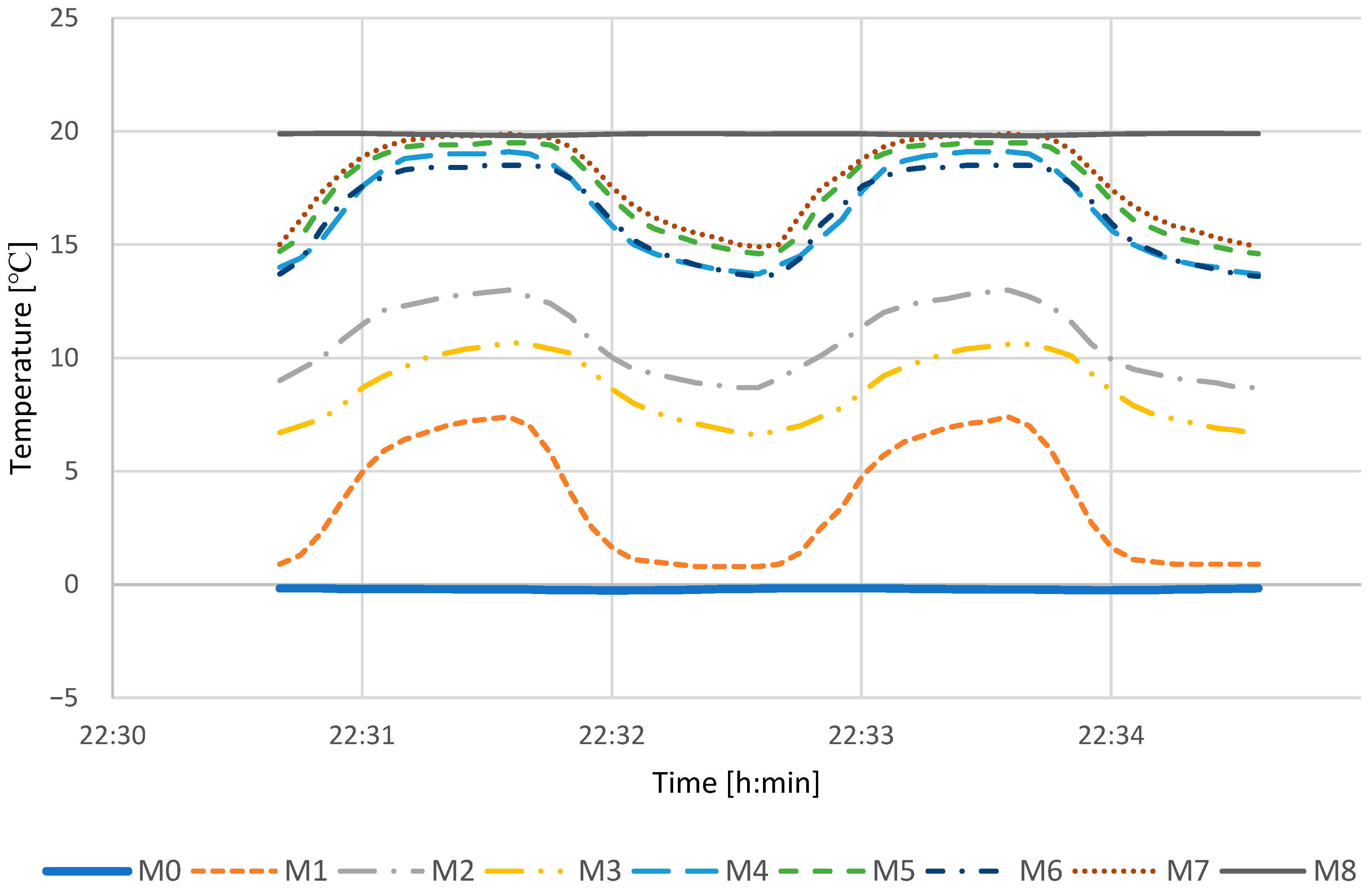
Figure 14 shows the waveform of temperature changes in the heat exchanger at an external temperature of 0 °C. Temperature changes are analogous to the external temperature −20 °C and −10 °C. However, with the external temperature at 0 °C, the average supplied air temperature for the case study was 15.1 °C. The lowest recorded values were obtained at the M1 thermocouple located in the air intake/exhaust.
The smallest temperature amplitudes for the highest external temperature result from the smallest difference between the indoor air temperature and the external air temperature.
Table 5, Table 6 and Table 7 show the values of heat recovery efficiency depending on the phase change material used, the temperature of the indoor air and the external air and cycle length.
The analysis of the unit’s operation using a 10 mm diameter cylinder heat exchanger 1 (Table 5) showed the best efficiency with jojoba oil regardless of cycle length and external temperature. In the 1 min cycle, the highest efficiency was 76.29%, in the 2 min cycle 74.16%, in the 3 min cycle 73.45%, and in the 5 min cycle 70.63%. These values were obtained for an external air temperature of 0 °C. The heat exchanger with jojoba oil achieved the lowest efficiency (67.22%) in a 5 min cycle at an external air temperature of −20 °C. The lowest efficiency was achieved by heat exchanger 1 filled with water in a 5 min cycle (65.93%), at a temperature of −20 °C. For comparison, an empty heat exchanger was analysed, which achieved the lowest efficiency in each variant of the cycle length and the external air temperature, which means a significant impact of the phase change material on heat recovery.
Using heat exchanger 2 with 25 mm diameter cylinders, it was again shown that the best efficiency is achieved with one-minute cycles (Table 6).
The highest efficiencies were observed for water, but during the experiment, the high thermal expansion of water caused damage to the heat exchanger. The use of jojoba oil was associated with only slightly lower efficiencies (differences ranged from 0.57 to 4.91 percentage points). In a 1 min cycle, the highest efficiency was 61%, in a 2 min cycle 57.22%, in a 3 min cycle 55.05%, and 51.68% in a 5 min cycle. Similarly to heat exchanger 1, the highest efficiencies occurred at an external temperature of 0 °C. The lowest efficiency of heat exchanger 2 with jojoba oil occurred in a 5 min cycle, at a temperature of −20 °C and amounted to 47.57%. As in the case of heat exchanger 1, the empty heat exchanger had the lowest efficiency.
Heat exchanger 3 (Table 7) showed the lowest heat recovery efficiencies in each configuration. However, the results are also affected by a 214% and 123% smaller exchange area compared to heat exchangers 1 and 2. At the same time, it is difficult to indicate the material that will be the most appropriate for heat exchanger 3. In the shortest cycle (1 min), the highest efficiency was achieved by jojoba oil: 53.18% for 0 °C, 50.68% for −10 °C and 49.83% for −20 °C. In a 2 min cycle at 0 °C, coconut oil turned out to be the best (51.89%), but at lower temperatures, water was better. Similarly, in a 3 min cycle at 0 °C, 49.99% was obtained for coconut oil, for lower temperatures water and jojoba oil had higher efficiencies. In a 5 min cycle, the highest efficiency was achieved by the water-filled heat exchanger and the maximum efficiency value is 48.65% at the temperature of 0 °C.
A comparison of all the results obtained showed that the shape of the heat exchanger has the greatest influence on the efficiency of the unit. It was also noted that the shortest cycles produced the best results. Attention should also be paid to the phase change material filling the heat exchanger, the selection of which should also depend on the shape of the heat exchanger.
The obtained efficiency results were subjected to statistical analysis using the Spearman correlation, carried out for three variables: type of heat exchanger, length of the duty cycle and external temperature. Table 8 summarises the results of the analysis.
For the measurements obtained:
- There is a significant negative correlation between the efficiency results and the type of heat exchanger (r = −0.880, p < 0.001). The larger the diameter of the heat exchanger cylinders, the lower the efficiency.
- There is a significant negative correlation between efficiency results and duty cycle length (r = −0.330, p < 0.001). The longer the cycle, the lower the efficiency.
- There is a significant positive correlation between the results and the external temperature (r = 0.162, p < 0.001). The higher the temperature of the external environment, the higher the efficiency.
5. Discussion
Energy storage in the studied heat exchanger takes place during the exhaust air cycle, and during the air supply, it is transferred to the air stream raising its temperature. There are many materials capable of storing large amounts of heat during a phase transformation and releasing the same amount of heat in the reverse process. For pure materials, the phase change takes place at the same compound-specific temperature and the melting and solidification process can be repeated over many cycles, with no change in the physico-chemical properties of phase change materials [36]. Phase change materials have a higher heat capacity due to their physical parameters of specific heat and latent heat required for phase change. The increased amount of heat required for phase change (latent heat) at given operating temperatures can be used for more efficient heat recovery [23]. The research carried out extends the knowledge of how heat recovery can be achieved in decentralised façade units. So far, few studies have investigated this subject. Similar studies using phase change materials in a heat exchanger for a reversible ventilation device integrated with the wall were carried out by Pekdogan T. et al. [37]. The heat exchanger they studied had dimensions of 15 cm × 15 cm × 15 cm and consisted of 100 copper tubes with an outer diameter of 4.76 mm and a wall thickness of 0.3 mm. The heat exchanger was filled with PCM—RT27. The tests were carried out only in summer conditions for cycles of 15 min, 20 min, 30 min. Efficiency rates of between 25 and 55% were achieved. Similarly, the studies presented in this study confirmed that extending the cycle time adversely affects efficiency. The most popular solution when using local ventilation is the use of ceramic heat exchangers, which, as shown by Zemitis J. and Bogdanovics R. [38], achieve an average heat recovery efficiency of 73%. These values are comparable to those presented in this study.
The next steps for further consideration could be to change the design of the heat exchanger (diameter of the cylinders, distance between them, change in geometry or material of the heat exchanger), to use other heat accumulating material, as well as to consider changing the cycle length and flow rate. In further analysis, CFD (Computational Fluid Dynamics) simulations will be carried out. CFD simulations can be helpful in optimising the solution, reducing the time and cost of subsequent studies. The results obtained in this study can be used to validate the simulation model.
6. Summary and Conclusions
The analysis showed that the best efficiency of the unit is achieved when using a heat exchanger with the smallest diameter cylinders and using the shortest possible cycles. In the tests carried out, the best results were obtained using a heat exchanger with 313 cylinders with an external diameter of 10 mm and a wall thickness of 1 mm.
Based on the study, it can be concluded that:
- The highest efficiency was achieved for heat exchanger 1, and at an external temperature of 0 °C it equals 76.29% for a 1 min cycle, 74.16% for a 2 min cycle, 73.45% for a 3 min cycle, and 70.63% for a 5 min cycle. The performance result is also influenced by a larger exchange surface of 214% and 123% compared to heat exchangers 2 and 3.
- The highest efficiency was achieved for the 1 min supply/exhaust cycle, and it was 76.29% at 0 °C, 75.72% at −10 °C, and 73.56% at −20 °C.
- The lowest efficiencies were obtained for heat exchanger 3, where the maximum obtained efficiency was 53.18% for the 1 min cycle, jojoba oil at 0 °C. Other variants of cycle length and external temperatures were associated with efficiencies below 50%. The performance result is also influenced by the lower exchange surface by 68% and 55% compared to heat exchangers 1 and 2.
In summary, it can be stated that heat exchanger 3 with a cylinder diameter of 40 mm should be eliminated from further analysis of solutions because the efficiency achieved by it is not satisfactory. The best solution is heat exchanger 1 filled with jojoba oil with efficiencies greater than 70%. In order to further increase its efficiency, it will be advisable to look for other phase change materials with better thermodynamic properties. CFD simulation of the heat exchanger will be helpful in this regard.
Author Contributions
Conceptualization, E.Z.-Ś.; Methodology, B.G.; Validation, B.G.; Investigation, B.G.; Data curation, B.G.; Writing—original draft, B.G.; Writing—review & editing, E.Z.-Ś.; Supervision, E.Z.-Ś.; Funding acquisition, E.Z.-Ś. All authors have read and agreed to the published version of the manuscript.
Funding
This research was funded by the program of the Minister of Science and Higher Education under the name: “Regional Initiative of Excellence” in 2019–2023 project number 025/RID/2018/19, financing amount PLN 12,000,000.
Data Availability Statement
The data presented in this study are available on request from the corresponding author.
Conflicts of Interest
The authors declare no conflict of interest.
References
- Cincinelli, A.; Martellini, T. Indoor Air Quality and Health. Int. J. Environ. Res. Public Health 2017, 14, 1286. [Google Scholar] [CrossRef] [PubMed] [Green Version]
- Telejko, M.; Zender-Świercz, E.; Zander-Świercz, E. Attempt to Improve Indoor Air Quality in Kindergartens. Procedia Eng. 2016, 161, 1704–1709. [Google Scholar] [CrossRef] [Green Version]
- Dodoo, A. Primary energy and economic implications of ventilation heat recovery for a multi-family building in a Nordic climate. J. Build. Eng. 2020, 31, 101391. [Google Scholar] [CrossRef]
- Mikola, A.; Kalamees, T.; Kõiv, T.-A. Performance of ventilation in Estonian apartment buildings. Energy Procedia 2017, 132, 963–968. [Google Scholar] [CrossRef]
- Alonso, M.J.; Liu, P.; Mathisen, H.M.; Ge, G.; Simonson, C. Review of heat/energy recovery exchangers for use in ZEBs in cold climate countries. Build. Environ. 2015, 84, 228–237. [Google Scholar] [CrossRef]
- Zhang, J.; Fung, A.S.; Jhingan, S. Analysis and feasibility study of residential integrated heat and energy recovery ventilator with built-in economizer using an excel spreadsheet program. Energy Build. 2014, 75, 430–438. [Google Scholar] [CrossRef]
- Zhang, L.; Jiang, Y. Heat and mass transfer in a membrane-based energy recovery ventilator. J. Membr. Sci. 1999, 163, 29–38. [Google Scholar] [CrossRef]
- Manz, H.; Huber, H.; Schälin, A.; Weber, A.; Ferrazzini, M.; Studer, M. Performance of single room ventilation units with recuperative or regenerative heat recovery. Energy Build. 2000, 31, 37–47. [Google Scholar] [CrossRef]
- Hurnik, M.; Specjal, A.; Popiolek, Z. On-site diagnosis of hybrid ventilation system in a renovated single-family house. Energy Build. 2017, 149, 123–132. [Google Scholar] [CrossRef]
- Ratajczak, K.; Szczechowiak, E. Energy consumption decreasing strategy for indoor swimming pools—Decentralized Ventilation system with a heat pump. Energy Build. 2020, 206, 109574. [Google Scholar] [CrossRef]
- Merzkirch, A.; Maas, S.; Scholzen, F.; Waldmann, D. A semi-centralized, valveless and demand controlled ventilation system in comparison to other concepts in field tests. Build. Environ. 2015, 93, 21–26. [Google Scholar] [CrossRef]
- Merzkirch, A.; Maas, S.; Scholzen, F.; Waldmann, D. Field tests of centralized and decentralized ventilation units in residential buildings—Specific fan power, heat recovery efficiency, shortcuts and volume flow unbalances. Energy Build. 2016, 116, 376–383. [Google Scholar] [CrossRef]
- Wulfinghoff, P.E. Multiple-zone HVAC: An Obsolete Template. Energy Eng. 2011, 108, 44–56. [Google Scholar] [CrossRef]
- Besant, R.; Simonson, C. Air-to-air exchangers. ASHRAE J. 2003, 45, 42. [Google Scholar]
- Besant, R.W.; Simonson, C.J. Air-to-air energy recovery. ASHRAE J. 2000, 42, 31–43. [Google Scholar]
- Dieckmann, J.; Roth, K.W.; Brodrick, J. Air-to-air energy recovery heat exchangers. ASHRAE J. 2003, 45, 57. [Google Scholar]
- Zender–Świercz, E. A Review of Heat Recovery in Ventilation. Energies 2021, 14, 1759. [Google Scholar] [CrossRef]
- Mahdi, J.M.; Mohammed, H.I.; Talebizadehsardari, P. A new approach for employing multiple PCMs in the passive thermal management of photovoltaic modules. Sol. Energy 2021, 222, 160–174. [Google Scholar] [CrossRef]
- Krasoń, J. Możliwości zastosowania materiałów zmiennofazowych w pasywnych rozwiązaniach ściennych elementów murowych, JCEEA, t. Czas. Inżynierii Lądowej Sr. Archit. 2014, 61, 297–306. [Google Scholar]
- Hatamleh, R.I.; Abu-Hamdeh, N.H.; Bantan, R.A. Integration of a solar air heater to a building equipped with PCM to reduce the energy demand. J. Build. Eng. 2022, 48, 103948. [Google Scholar] [CrossRef]
- Kasaeian, A.; Bahrami, L.; Pourfayaz, F.; Khodabandeh, E.; Yan, W.-M. Experimental studies on the applications of PCMs and nano-PCMs in buildings: A critical review. Energy Build. 2017, 154, 96–112. [Google Scholar] [CrossRef]
- Ning, M.; Jingyu, H.; Dongmei, P.; Shengchun, L.; Mengjie, S. Investigations on thermal environment in residential buildings with PCM embedded in external wall. Energy Procedia 2017, 142, 1888–1895. [Google Scholar] [CrossRef]
- Melcer, A.; Klugmann-Radziemska, E.; Lewandowski, W.; Iwaniak-Lewandowska, W. Materiały zmiennofazowe dostępne na rynku. Właściwości i zastosowanie. Przemysł Chem. 2012, 91, 1733–1742. [Google Scholar]
- Nemati, H.; Souriaee, V.; Habibi, M.; Vafai, K. Design and Taguchi-based optimization of the latent heat thermal storage in the form of structured porous-coated pipe. Energy 2023, 263, 125947. [Google Scholar] [CrossRef]
- Koç, A.; Yağlı, H.; Bilgic, H.H.; Koç, Y.; Özdemir, A. Performance analysis of a novel organic fluid filled regenerative heat exchanger used heat recovery ventilation (OHeX-HRV) system. Sustain. Energy Technol. Assess. 2020, 41, 100787. [Google Scholar] [CrossRef]
- Pekdogan, T.; Tokuç, A.; Ezan, M.A.; Başaran, T. Experimental investigation of a decentralized heat recovery ventilation system. J. Build. Eng. 2021, 35, 102009. [Google Scholar] [CrossRef]
- Chang, C.-C.; Lai, C.-H.; Yang, C.-M.; Chiang, Y.-C.; Chen, S.-L. Thermal performance enhancement of a periodic total heat exchanger using energy-storage material. Energy Build. 2013, 67, 579–586. [Google Scholar] [CrossRef]
- Al-Zubaydi, A.Y.T.; Hong, G. Experimental investigation of counter flow heat exchangers for energy recovery ventilation in cooling mode. Int. J. Refrig. 2018, 93, 132–143. [Google Scholar] [CrossRef]
- Eisapour, A.H.; Eisapour, M.; Mohammed, H.I.; Shafaghat, A.; Ghalambaz, M.; Talebizadehsardari, P. Optimum design of a double elliptical latent heat energy storage system during the melting process. J. Energy Storage 2021, 44, 103384. [Google Scholar] [CrossRef]
- Najim, F.T.; Bahlekeh, A.; Mohammed, H.I.; Dulaimi, A.; Abed, A.M.; Ibrahem, R.K.; Al-Qrimli, F.A.; Mahmoud, M.Z.; Awrejcewicz, J.; Pawłowski, W. Evaluation of Melting Mechanism and Natural Convection Effect in a Triplex Tube Heat Storage System with a Novel Fin Arrangement. Sustainability 2022, 14, 10982. [Google Scholar] [CrossRef]
- Tiji, M.E.; Al-Azzawi, W.K.; Mohammed, H.I.; Dulaimi, A.; Rashid, F.L.; Mahdi, J.M.; Majdi, H.S.; Talebizadehsardari, P.; Ali, H.M. Thermal Management of the Melting Process in a Latent Heat Triplex Tube Storage System Using Different Configurations of Frustum Tubes. J. Nanomater. 2022, 2022, 1–14. [Google Scholar] [CrossRef]
- Han, H.; Kwon, Y.-I. Inhaling/Exhaling Heat Recovery Ventilator Using the Concept of Alternating-Current Ventilation. HVACR Res. 2006, 12, 843–859. [Google Scholar] [CrossRef]
- Zender-Świercz, E. Utility Model Number P.432536 Accumulation Heat Exchanger Especially for Facade Ventilation; 2022; p. 432536. [Google Scholar]
- PN-EN 16798-1: 2019-06; Energy Performance of Buildings—Ventilation for Buildings—Part 1: Indoor Environmental Input Parameters for Design and Assessment of Energy Performance of Buildings Addressing Indoor Air Quality. Thermal Environment, Lighting and Acoustics. Polish Committee for Standardization: Warsaw, Poland, 2019.
- PN-EN 12831:2017-08; Charakterystyka energetyczna budynków—Metoda obliczania projektowego obciążenia cieplnego—Część 1: Obciążenie cieplne. Polish Committee for Standardization: Warsaw, Poland, 2017.
- Ciulla, G.; Brano, V.L.; Cellura, M.; Franzitta, V.; Milone, D. A Finite Difference Model of a PV-PCM System. Energy Procedia 2012, 30, 198–206. [Google Scholar] [CrossRef] [Green Version]
- Pekdogan, T.; Tokuç, A.; Ezan, M.A.; Başaran, T. Experimental investigation on heat transfer and air flow behavior of latent heat storage unit in a facade integrated ventilation system. J. Energy Storage 2021, 44, 103367. [Google Scholar] [CrossRef]
- Zemitis, J.; Bogdanovics, R. Heat recovery efficiency of local decentralized ventilation device at various pressure differ-ences. Mag. Civ. Eng. 2020, 2, 120–128. [Google Scholar]
Figure 1.
Scheme of the experimental setup.
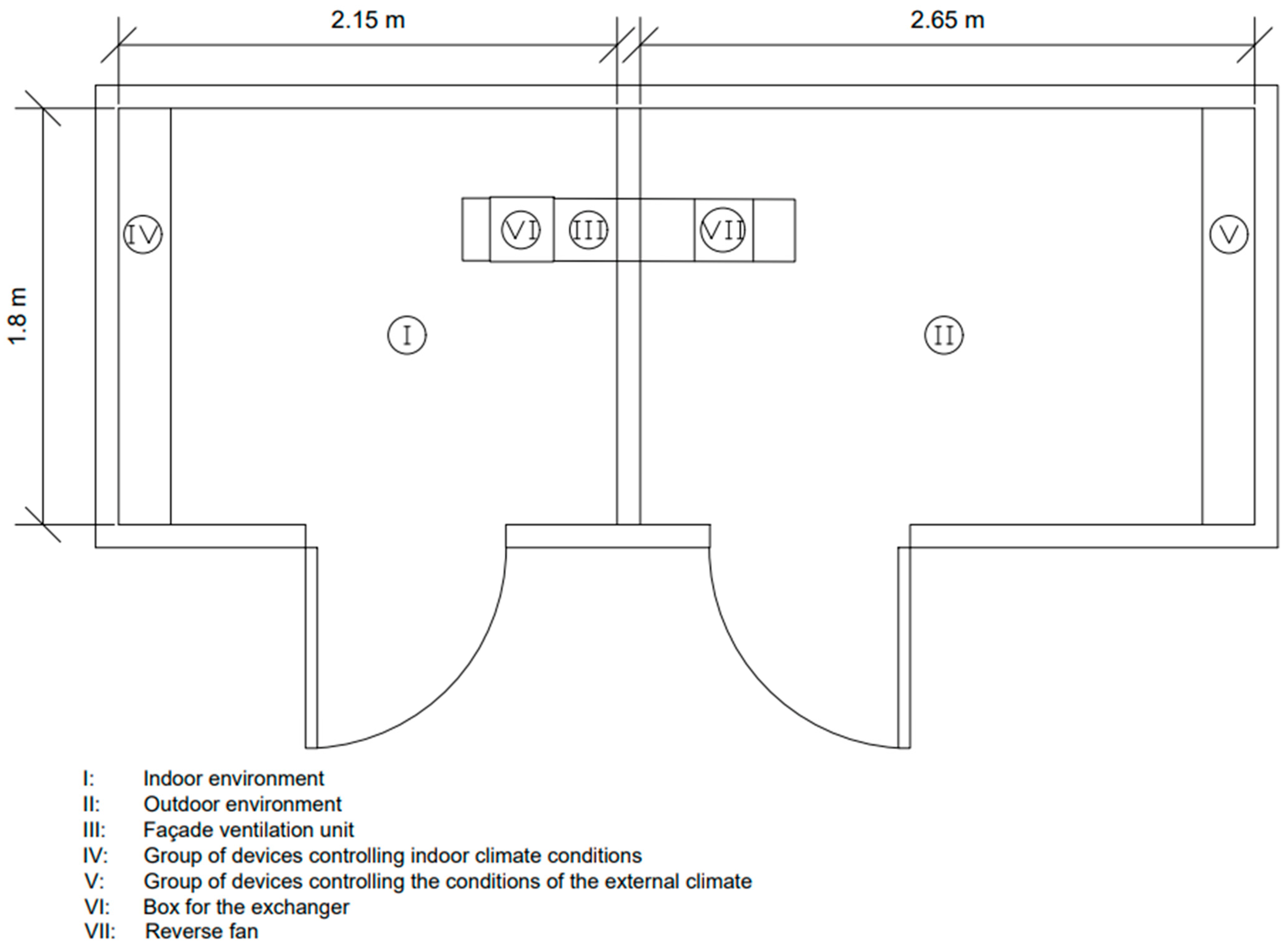
Figure 2.
Façade ventilation unit (view from the side simulating indoor environment conditions).
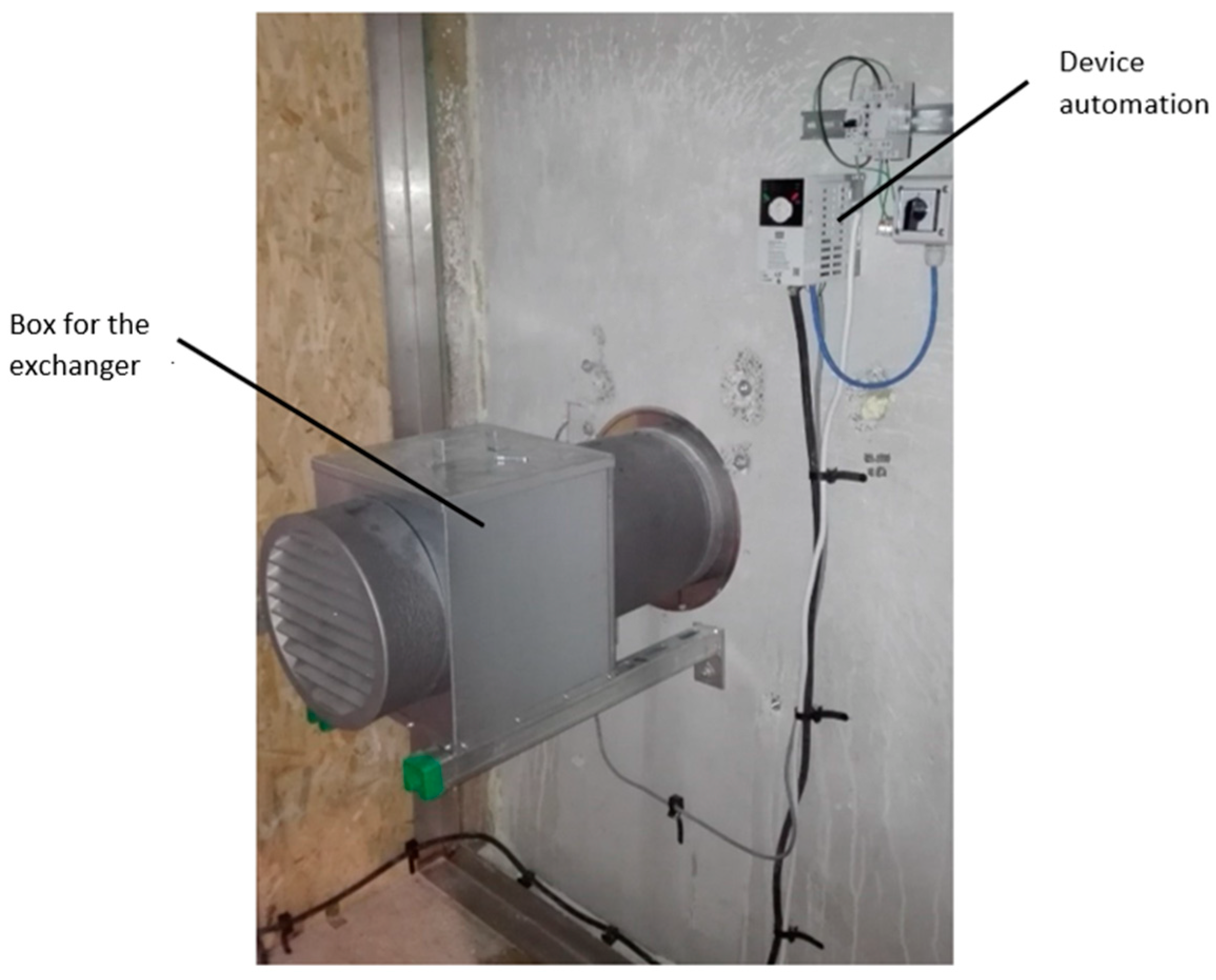
Figure 3.
Façade ventilation unit (view from the side simulating external environment conditions).

Figure 4.
Automated control system for the fan.

Figure 5.
Heat exchanger 1 made of cylinders with an external diameter of 10 mm and a wall thickness of 1 mm.
Figure 5.
Heat exchanger 1 made of cylinders with an external diameter of 10 mm and a wall thickness of 1 mm.
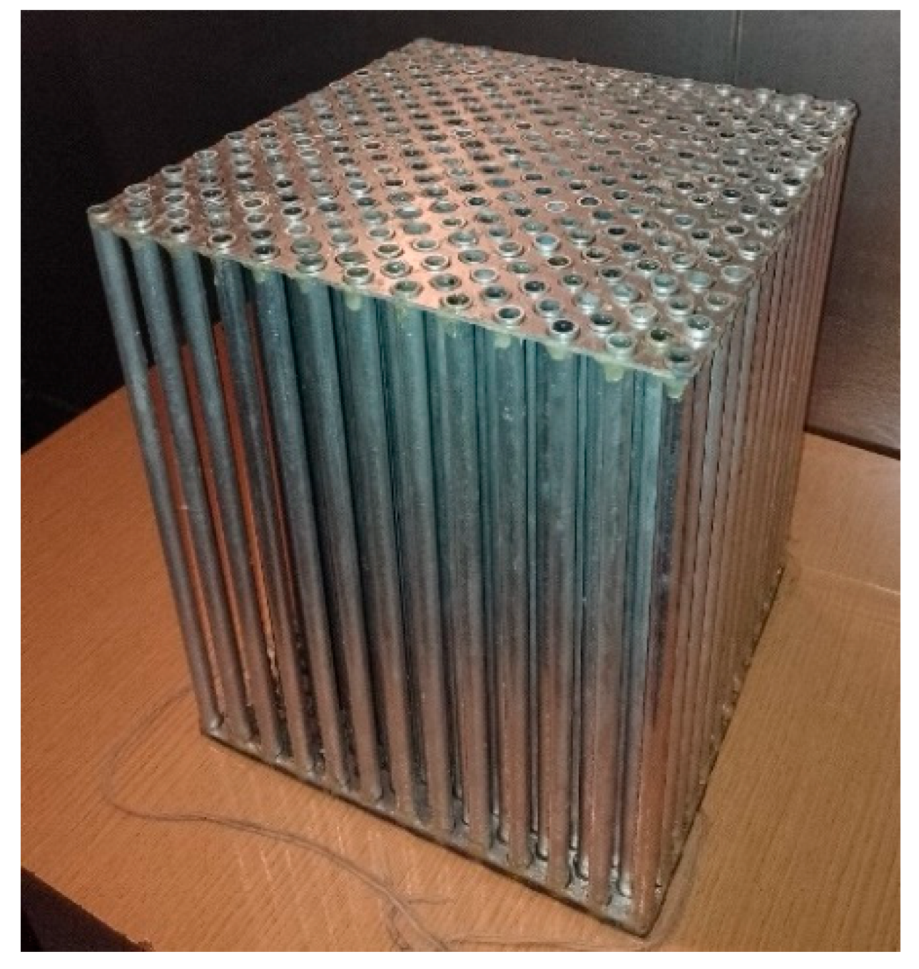
Figure 6.
Heat exchanger 2 made of cylinders with an external diameter of 25 mm and a wall thickness of 1 mm.
Figure 6.
Heat exchanger 2 made of cylinders with an external diameter of 25 mm and a wall thickness of 1 mm.

Figure 7.
Heat exchanger 3 made of cylinders with an external diameter of 40 mm and a wall thickness of 1 mm.
Figure 7.
Heat exchanger 3 made of cylinders with an external diameter of 40 mm and a wall thickness of 1 mm.
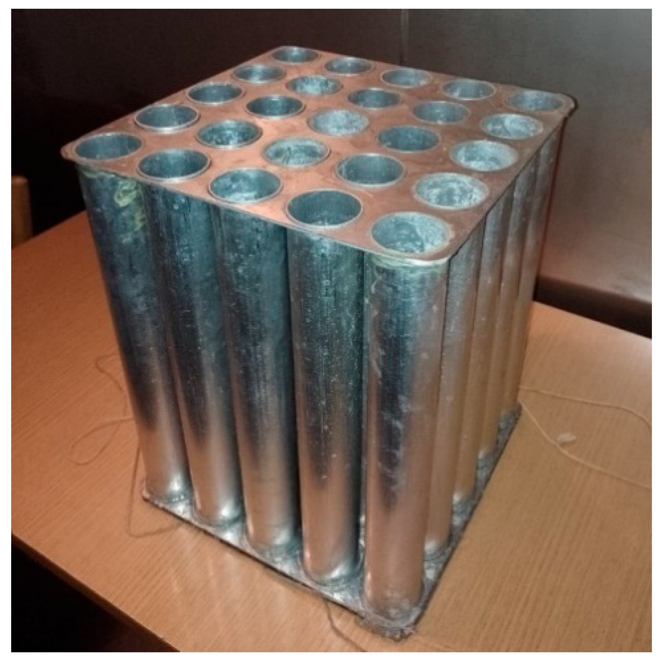
Figure 8.
Design of cylinder system with an external diameter of 10 mm in heat exchanger 1.
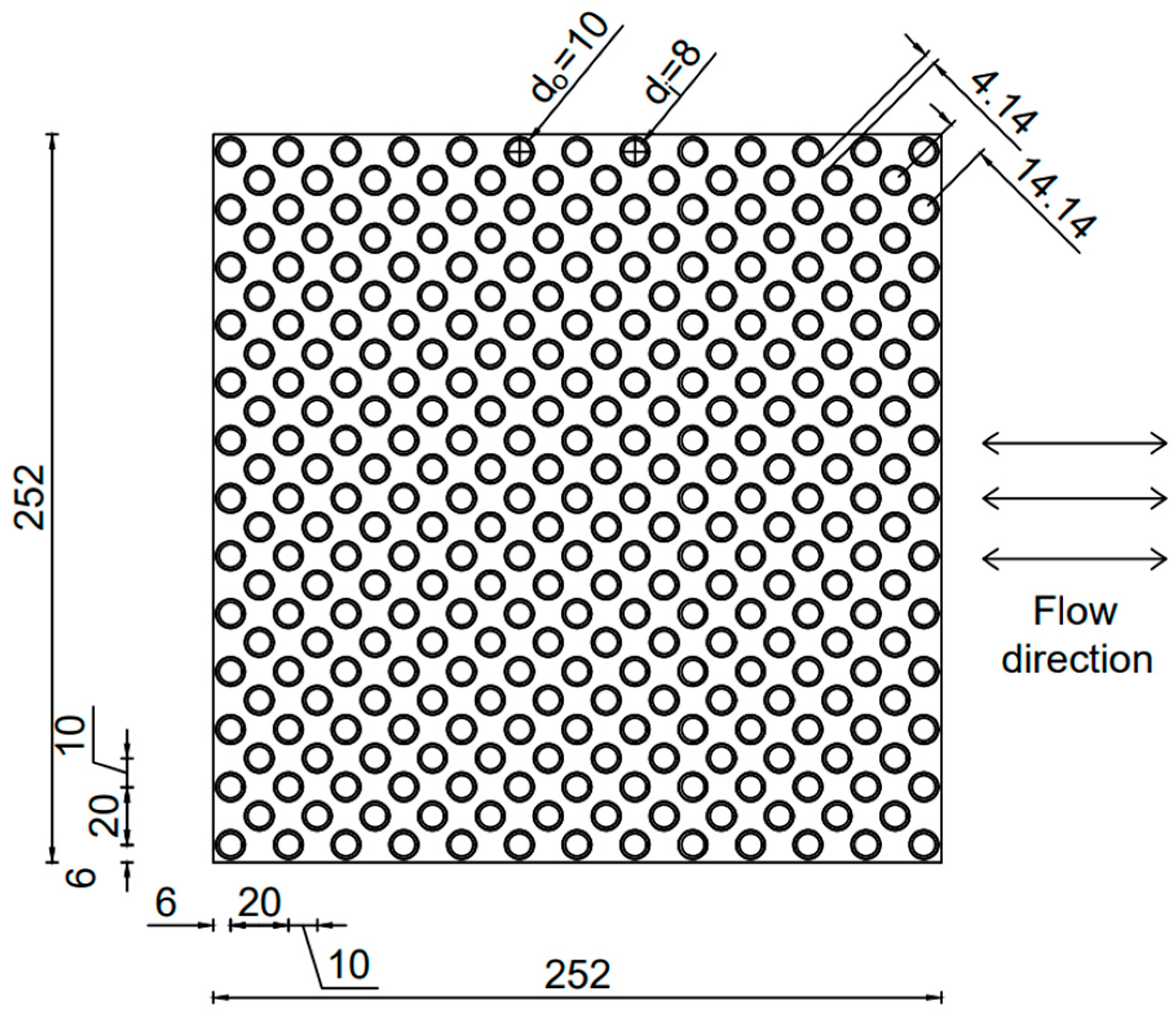
Figure 9.
Design of cylinder system with an external diameter of 25 mm in heat exchanger 2.
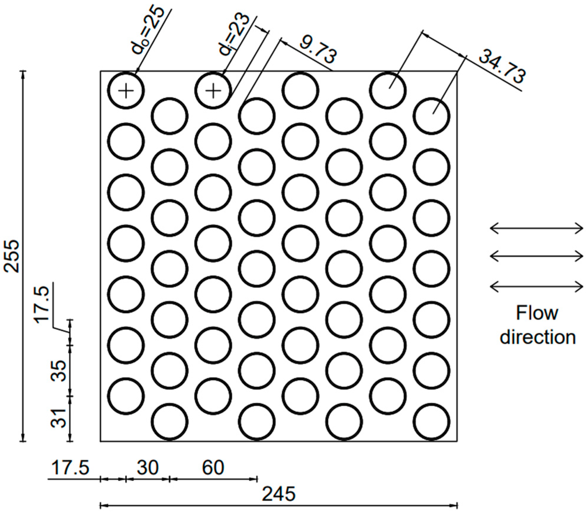
Figure 10.
Design of cylinder system with an external diameter of 40 mm in heat exchanger 3.

Figure 11.
Diagram of the arrangement of measuring points (thermocouples).
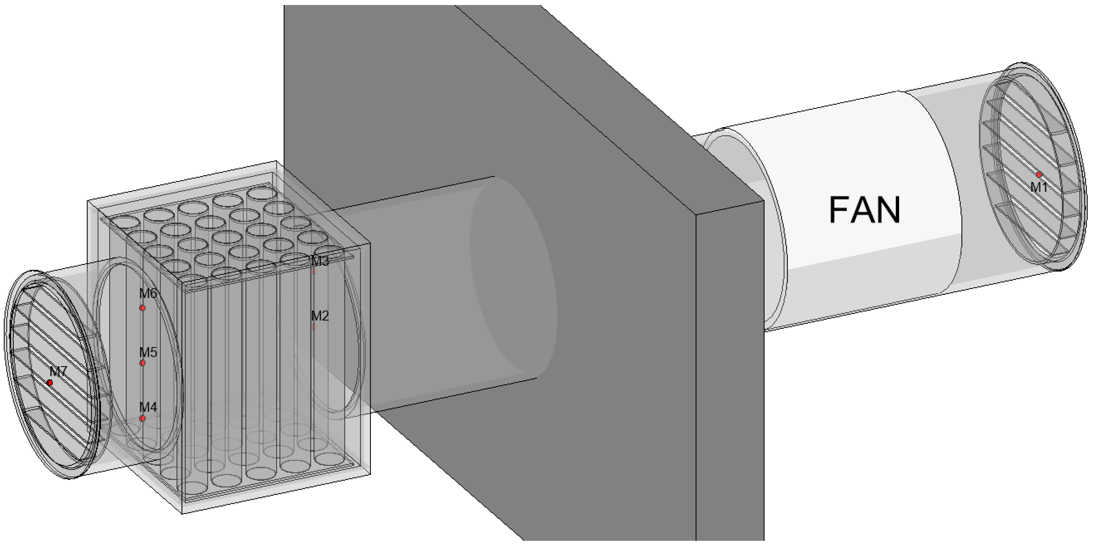
Figure 12.
Change in temperature in measuring points marked M0–M8, when the first heat exchanger, filled with jojoba oil, was used. The external temperature equals −20 °C and internal temperature equals 20 °C. The supply and exhaust cycles were 1 min. Temperature change wave.
Figure 12.
Change in temperature in measuring points marked M0–M8, when the first heat exchanger, filled with jojoba oil, was used. The external temperature equals −20 °C and internal temperature equals 20 °C. The supply and exhaust cycles were 1 min. Temperature change wave.
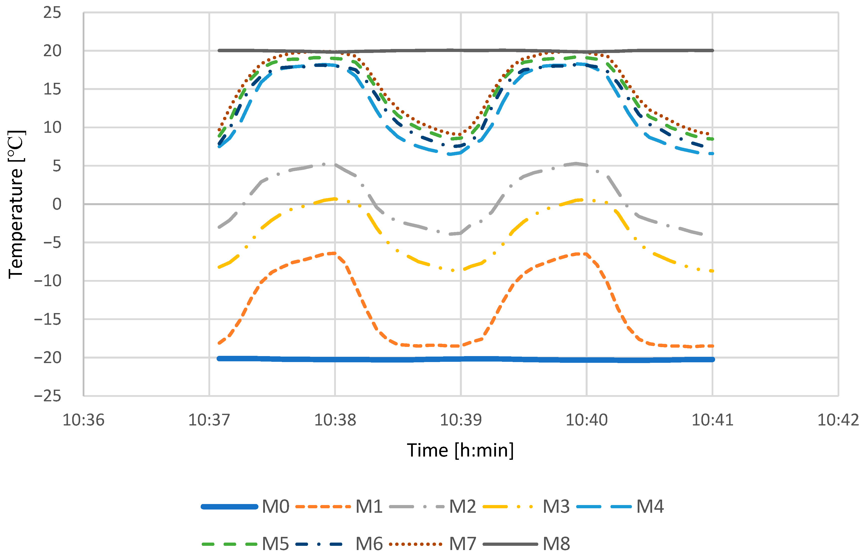
Figure 13.
Change in temperature in measuring points marked M0–M8, when the first heat exchanger filled with jojoba oil was used. The external temperature equals −10 °C and internal temperature equals 20 °C. The supply and exhaust cycles were 1 min.
Figure 13.
Change in temperature in measuring points marked M0–M8, when the first heat exchanger filled with jojoba oil was used. The external temperature equals −10 °C and internal temperature equals 20 °C. The supply and exhaust cycles were 1 min.
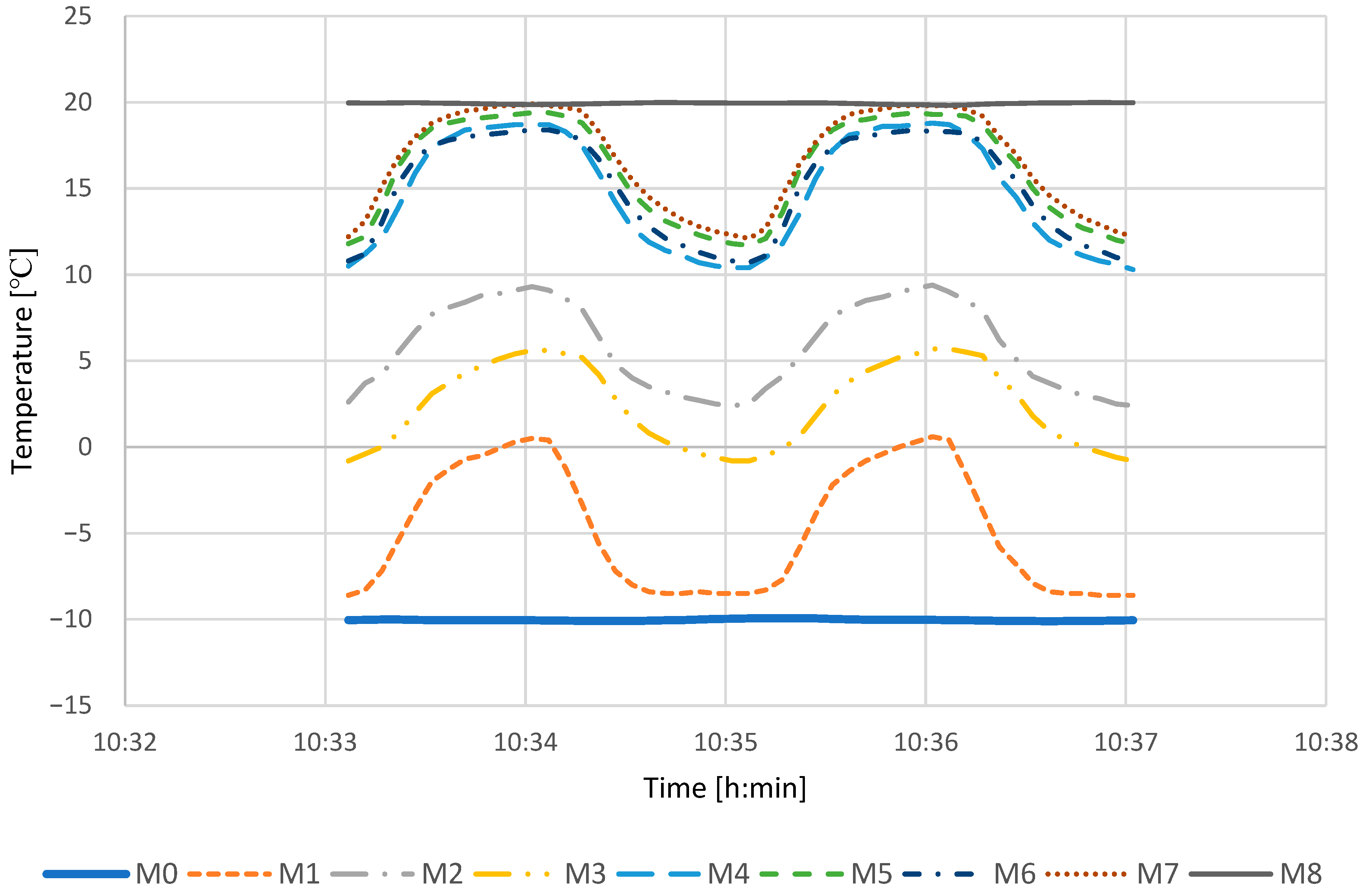
Figure 14.
Change in temperature in measuring points marked M0–M8, when the first heat exchanger, filled with jojoba oil, was used. The external temperature equals 0 °C and internal temperature equals 20 °C. The supply and exhaust cycles were 1 min.
Figure 14.
Change in temperature in measuring points marked M0–M8, when the first heat exchanger, filled with jojoba oil, was used. The external temperature equals 0 °C and internal temperature equals 20 °C. The supply and exhaust cycles were 1 min.

Table 1.
Climate chamber parameters.
| Chamber Simulating an Indoor Environment | Chamber Simulating an External Environment | |
|---|---|---|
| Temperature range | −5 to +50 °C | −30 to 80 °C |
| Setting step | 0.1 K | 0.1 K |
| Length | 2.15 m | 2.65 m |
| Width | 1.8 m | 1.8 m |
| Height | 2.3 m | 2.3 m |
Table 2.
Heat exchangers parameters.
| Heat Exchanger 1 | Heat Exchanger 2 | Heat Exchanger 3 | |
|---|---|---|---|
| Tube external diameter—do (mm) | 10 | 25 | 40 |
| Tube inside diameter—di (mm) | 8 | 23 | 38 |
| Transverse tube pitch—St (mm) | 20 | 35 | 50 |
| Row pitch—Sl (mm) | 10 | 30 | 50 |
| Tube layout | staggered | staggered | inline |
| Number of rows—N | 25 | 8 | 5 |
| Number of tubes—n | 313 | 56 | 25 |
| Tube height—H (mm) | 300 | 300 | 300 |
| Surface area of a heat exchanger—A (m2) | 2.95 | 1.32 | 0.94 |
| Volume of PCM—V (dm3) | 4.72 | 6.98 | 8.51 |
Table 3.
Thermophysical properties of selected phase change materials.
| Phase Change Material | Specific Heat J/gK | Heat Melting J/g | Heat Clotting J/g | Temperature Melting °C | Capacity Thermal J/K |
|---|---|---|---|---|---|
| coconut oil | 1.67 | 103.02 | 86.68 | 25 | 0.0156 |
| jojoba oil | 10.81 | 130.7 | 132.6 | 14.7 | 0.1046 |
| water | 19.88 | 330.4 | 258.9 | 0.3 | 0.260 |
Table 4.
Thermocouple parameters—Pt100.
| Resistance temperature detectors—Pt100 | |
|---|---|
| Measuring range | −200.00 °C to +400.00 °C |
| Resolution | 0.01 K |
| Linearisation accuracy | ±0.05 K |
| Connector programming | ZA 9030 FS2 |
Table 5.
Unit efficiency with heat exchanger 1.
| Time | Material | External Temperature | Internal Temperature | Device Efficiency |
|---|---|---|---|---|
| 1 min | jojoba oil | 0 °C | 20 °C | 76.29% |
| 1 min | coconut oil | 0 °C | 20 °C | 75.10% |
| 1 min | empty | 0 °C | 20 °C | 72.70% |
| 1 min | water | 0 °C | 20 °C | 72.15% |
| 2 min | jojoba oil | 0 °C | 20 °C | 74.19% |
| 2 min | coconut oil | 0 °C | 20 °C | 72.61% |
| 2 min | empty | 0 °C | 20 °C | 69.49% |
| 2 min | water | 0 °C | 20 °C | 70.78% |
| 3 min | jojoba oil | 0 °C | 20 °C | 73.45% |
| 3 min | coconut oil | 0 °C | 20 °C | 71.29% |
| 3 min | empty | 0 °C | 20 °C | 66.20% |
| 3 min | water | 0 °C | 20 °C | 69.90% |
| 5 min | jojoba oil | 0 °C | 20 °C | 70.63% |
| 5 min | coconut oil | 0 °C | 20 °C | 68.96% |
| 5 min | empty | 0 °C | 20 °C | 60.53% |
| 5 min | water | 0 °C | 20 °C | 68.55% |
| 1 min | jojoba oil | −10 °C | 20 °C | 75.72% |
| 1 min | coconut oil | −10 °C | 20 °C | 70.56% |
| 1 min | empty | −10 °C | 20 °C | 72.92% |
| 1 min | water | −10 °C | 20 °C | 71.30% |
| 2 min | jojoba oil | −10 °C | 20 °C | 71.94% |
| 2 min | coconut oil | −10 °C | 20 °C | 68.08% |
| 2 min | empty | −10 °C | 20 °C | 69.05% |
| 2 min | water | −10 °C | 20 °C | 69.61% |
| 3 min | jojoba oil | −10 °C | 20 °C | 70.45% |
| 3 min | coconut oil | −10 °C | 20 °C | 66.49% |
| 3 min | empty | −10 °C | 20 °C | 65.59% |
| 3 min | water | −10 °C | 20 °C | 68.73% |
| 5 min | jojoba oil | −10 °C | 20 °C | 67.83% |
| 5 min | coconut oil | −10 °C | 20 °C | 64.25% |
| 5 min | empty | −10 °C | 20 °C | 59.12% |
| 5 min | water | −10 °C | 20 °C | 67.27% |
| 1 min | jojoba oil | −20 °C | 20 °C | 73.56% |
| 1 min | coconut oil | −20 °C | 20 °C | 69.69% |
| 1 min | empty | −20 °C | 20 °C | 72.16% |
| 1 min | water | −20 °C | 20 °C | 70.17% |
| 2 min | jojoba oil | −20 °C | 20 °C | 71.05% |
| 2 min | coconut oil | −20 °C | 20 °C | 67.38% |
| 2 min | empty | −20 °C | 20 °C | 68.14% |
| 2 min | water | −20 °C | 20 °C | 69.29% |
| 3 min | jojoba oil | −20 °C | 20 °C | 69.39% |
| 3 min | coconut oil | −20 °C | 20 °C | 65.82% |
| 3 min | empty | −20 °C | 20 °C | 64.67% |
| 3 min | water | −20 °C | 20 °C | 67.70% |
| 5 min | jojoba oil | −20 °C | 20 °C | 67.22% |
| 5 min | coconut oil | −20 °C | 20 °C | 63.48% |
| 5 min | empty | −20 °C | 20 °C | 57.98% |
| 5 min | water | −20 °C | 20 °C | 65.93% |
Table 6.
Unit efficiency with heat exchanger 2.
| Time | Material | External Temperature | Internal Temperature | Device Efficiency |
|---|---|---|---|---|
| 1 min | jojoba oil | 0 °C | 20 °C | 61.00% |
| 1 min | coconut oil | 0 °C | 20 °C | 56.82% |
| 1 min | empty | 0 °C | 20 °C | 59.76% |
| 1 min | water | 0 °C | 20 °C | 61.57% |
| 2 min | jojoba oil | 0 °C | 20 °C | 57.22% |
| 2 min | coconut oil | 0 °C | 20 °C | 54.19% |
| 2 min | empty | 0 °C | 20 °C | 56.56% |
| 2 min | water | 0 °C | 20 °C | 55.22% |
| 3 min | jojoba oil | 0 °C | 20 °C | 55.05% |
| 3 min | coconut oil | 0 °C | 20 °C | 52.22% |
| 3 min | empty | 0 °C | 20 °C | 53.20% |
| 3 min | water | 0 °C | 20 °C | 56.35% |
| 5 min | jojoba oil | 0 °C | 20 °C | 51.68% |
| 5 min | coconut oil | 0 °C | 20 °C | 49.28% |
| 5 min | empty | 0 °C | 20 °C | 47.00% |
| 5 min | water | 0 °C | 20 °C | 54.64% |
| 1 min | jojoba oil | −10 °C | 20 °C | 58.46% |
| 1 min | coconut oil | −10 °C | 20 °C | 52.41% |
| 1 min | empty | −10 °C | 20 °C | 56.56% |
| 1 min | water | −10 °C | 20 °C | 59.48% |
| 2 min | jojoba oil | −10 °C | 20 °C | 54.69% |
| 2 min | coconut oil | −10 °C | 20 °C | 49.91% |
| 2 min | empty | −10 °C | 20 °C | 53.13% |
| 2 min | water | −10 °C | 20 °C | 54.65% |
| 3 min | jojoba oil | −10 °C | 20 °C | 52.79% |
| 3 min | coconut oil | −10 °C | 20 °C | 48.19% |
| 3 min | empty | −10 °C | 20 °C | 49.97% |
| 3 min | water | −10 °C | 20 °C | 55.59% |
| 5 min | jojoba oil | −10 °C | 20 °C | 49.62% |
| 5 min | coconut oil | −10 °C | 20 °C | 45.40% |
| 5 min | empty | −10 °C | 20 °C | 44.07% |
| 5 min | water | −10 °C | 20 °C | 50.64% |
| 1 min | jojoba oil | −20 °C | 20 °C | 56.68% |
| 1 min | coconut oil | −20 °C | 20 °C | 55.08% |
| 1 min | empty | −20 °C | 20 °C | 56.60% |
| 1 min | water | −20 °C | 20 °C | 58.72% |
| 2 min | jojoba oil | −20 °C | 20 °C | 52.68% |
| 2 min | coconut oil | −20 °C | 20 °C | 51.94% |
| 2 min | empty | −20 °C | 20 °C | 52.98% |
| 2 min | water | −20 °C | 20 °C | 56.22% |
| 3 min | jojoba oil | −20 °C | 20 °C | 50.41% |
| 3 min | coconut oil | −20 °C | 20 °C | 49.39% |
| 3 min | empty | −20 °C | 20 °C | 49.29% |
| 3 min | water | −20 °C | 20 °C | 54.63% |
| 5 min | jojoba oil | −20 °C | 20 °C | 47.57% |
| 5 min | coconut oil | −20 °C | 20 °C | 45.84% |
| 5 min | empty | −20 °C | 20 °C | 42.56% |
| 5 min | water | −20 °C | 20 °C | 52.48% |
Table 7.
Unit efficiency with heat exchanger 3.
| Time | Material | External Temperature | Internal Temperature | Device Efficiency |
|---|---|---|---|---|
| 1 min | jojoba oil | 0 °C | 20 °C | 53.18% |
| 1 min | coconut oil | 0 °C | 20 °C | 49.13% |
| 1 min | empty | 0 °C | 20 °C | 49.32% |
| 1 min | water | 0 °C | 20 °C | 53.09% |
| 2 min | jojoba oil | 0 °C | 20 °C | 50.19% |
| 2 min | coconut oil | 0 °C | 20 °C | 51.89% |
| 2 min | empty | 0 °C | 20 °C | 46.8% |
| 2 min | water | 0 °C | 20 °C | 50.68% |
| 3 min | jojoba oil | 0 °C | 20 °C | 48.34% |
| 3 min | coconut oil | 0 °C | 20 °C | 49.99% |
| 3 min | empty | 0 °C | 20 °C | 44.34% |
| 3 min | water | 0 °C | 20 °C | 48.82% |
| 5 min | jojoba oil | 0 °C | 20 °C | 44.50% |
| 5 min | coconut oil | 0 °C | 20 °C | 43.98% |
| 5 min | empty | 0 °C | 20 °C | 39.86% |
| 5 min | water | 0 °C | 20 °C | 48.65% |
| 1 min | jojoba oil | −10 °C | 20 °C | 50.88% |
| 1 min | coconut oil | −10 °C | 20 °C | 50.79% |
| 1 min | empty | −10 °C | 20 °C | 45.89% |
| 1 min | water | −10 °C | 20 °C | 52.83% |
| 2 min | jojoba oil | −10 °C | 20 °C | 47.71% |
| 2 min | coconut oil | −10 °C | 20 °C | 47.77% |
| 2 min | empty | −10 °C | 20 °C | 43.41% |
| 2 min | water | −10 °C | 20 °C | 49.16% |
| 3 min | jojoba oil | −10 °C | 20 °C | 45.86% |
| 3 min | coconut oil | −10 °C | 20 °C | 45.63% |
| 3 min | empty | −10 °C | 20 °C | 40.85% |
| 3 min | water | −10 °C | 20 °C | 47.82% |
| 5 min | jojoba oil | −10 °C | 20 °C | 43.13% |
| 5 min | coconut oil | −10 °C | 20 °C | 42.55% |
| 5 min | empty | −10 °C | 20 °C | 36.39% |
| 5 min | water | −10 °C | 20 °C | 45.55% |
| 1 min | jojoba oil | −20 °C | 20 °C | 49.83% |
| 1 min | coconut oil | −20 °C | 20 °C | 48.28% |
| 1 min | empty | −20 °C | 20 °C | 44.88% |
| 1 min | water | −20 °C | 20 °C | 48.99% |
| 2 min | jojoba oil | −20 °C | 20 °C | 46.97% |
| 2 min | coconut oil | −20 °C | 20 °C | 46.31% |
| 2 min | empty | −20 °C | 20 °C | 42.05% |
| 2 min | water | −20 °C | 20 °C | 47.33% |
| 3 min | jojoba oil | −20 °C | 20 °C | 45.09% |
| 3 min | coconut oil | −20 °C | 20 °C | 44.37% |
| 3 min | empty | −20 °C | 20 °C | 39.14% |
| 3 min | water | −20 °C | 20 °C | 45.89% |
| 5 min | jojoba oil | −20 °C | 20 °C | 42.48% |
| 5 min | coconut oil | −20 °C | 20 °C | 41.21% |
| 5 min | empty | −20 °C | 20 °C | 34.45% |
| 5 min | water | −20 °C | 20 °C | 44.68% |
Table 8.
Spearman correlation.
| Variable | Measurement | |
|---|---|---|
| Heat exchanger | spearman correlation coefficient (r) | −0.880 |
| materiality level (p) | 0.000 | |
| sample size (N) | 1440 | |
| Cycle | spearman correlation coefficient (r) | −0.330 |
| materiality level (p) | 0.000 | |
| sample size (N) | 1440 | |
| External temperature | spearman correlation coefficient (r) | 0.162 |
| materiality level (p) | 0.000 | |
| sample size (N) | 1440 | |
Disclaimer/Publisher’s Note: The statements, opinions and data contained in all publications are solely those of the individual author(s) and contributor(s) and not of MDPI and/or the editor(s). MDPI and/or the editor(s) disclaim responsibility for any injury to people or property resulting from any ideas, methods, instructions or products referred to in the content. |
© 2023 by the authors. Licensee MDPI, Basel, Switzerland. This article is an open access article distributed under the terms and conditions of the Creative Commons Attribution (CC BY) license (https://creativecommons.org/licenses/by/4.0/).
Share and Cite
MDPI and ACS Style
Galiszewska, B.; Zender-Świercz, E. Heat Recovery Using PCM in Decentralised Façade Ventilation. Energies 2023, 16, 3310. https://doi.org/10.3390/en16083310
AMA Style
Galiszewska B, Zender-Świercz E. Heat Recovery Using PCM in Decentralised Façade Ventilation. Energies. 2023; 16(8):3310. https://doi.org/10.3390/en16083310
Chicago/Turabian StyleGaliszewska, Beata, and Ewa Zender-Świercz. 2023. "Heat Recovery Using PCM in Decentralised Façade Ventilation" Energies 16, no. 8: 3310. https://doi.org/10.3390/en16083310
Note that from the first issue of 2016, this journal uses article numbers instead of page numbers. See further details here.