Review

Ultra-Low-Temperature Refrigeration Systems: A Review and Performance Comparison of Refrigerants and Configurations

Department of Energy and Process Engineering, Norwegian University of Science and Technology (NTNU), 7491 Trondheim, Norway
*
Authors to whom correspondence should be addressed.
These authors contributed equally this work.
Energies 2023, 16(21), 7274; https://doi.org/10.3390/en16217274
Submission received: 20 September 2023 / Revised: 23 October 2023 / Accepted: 24 October 2023 / Published: 26 October 2023

Abstract

:
During the last decade, many industrial and medical applications have shown a requirement for low-temperature-cooling usage (from −40 to −80 °C), which cannot be efficiently obtained via the conventional refrigeration systems usually employed for medium-temperature applications (from 0 to −40 °C). A proper ultra-low-temperature (ULT) refrigeration system design is essential to achieve the desired output. The performance can be maximised via the suitable selection of the configuration and refrigerant for a specific temperature range. This work contributes a detailed overview of the different systems and refrigerants used in ultra-low-temperature applications. Different systems, such as single-stage vapour compression, multi-stage, cascade, auto-cascade, and air refrigeration cycles, are presented and discussed. An energy analysis is then carried out for these systems identifying the optimal system design and refrigerant selection to achieve the highest performance. This paper aims to provide the reader with a comprehensive background through an exhaustive review of refrigeration systems suitable for ultra-low-temperature applications. The effectiveness of these systems is proven numerically, mainly based on the temperature level and purpose of the application.

1. Introduction

ULT systems are gaining significant interest, and researchers are putting great effort into developing and identifying the most reliable and efficient solutions. The application of ULT technology is quite diverse, such as in the medical, industrial, and food sectors. According to the American Society of Heating, Refrigeration and Air-Conditioning Engineers (ASHRAE), ULT refrigeration systems are those that operate below −50 °C [1]. There are options available for ULT systems. However, the high cost of synthetic refrigerants and the new policy towards sustainable development have created a huge interest in natural, hydrocarbon, and mixture refrigerants. The F-Gas Regulation (EU 517/2014) aims to reduce the fluorinated greenhouse gas (F-gas) emissions in Europe by two-thirds by 2030 compared to 2014. Hydrofluorocarbons (HFCs) are refrigerants that are responsible for most F-gas emissions. The European Union has therefore set priorities to phase down HFCs following a reduction schedule that started in 2015 [2] and will continue to 2030 and beyond. HFC producers and consumers have been provided with HFC quotas for a progressive HFC phasedown. The F-Gas Regulation intends to cut F-gas emissions by two-thirds of the 2010 levels by 2030 by enhancing equipment leak-tightness, promoting more ecologically friendly gases, and restricting EU HFC sales through an HFC phasedown [3]. The F-Gas Regulation excludes the regulations pertaining to refrigeration below −50 °C in its low-GWP Alternative Refrigerants Evaluation Program (AREP), which can be explained by the limited number of units in use (in comparison to other applications) and the slower pace of development [4]. The target temperature of the product/environment and the application constitute the main influencing parameters to consider when selecting a refrigerant to achieve an optimal system performance. The flammability and toxicity of the refrigerant are also important to account for safety considerations. A limited number of natural refrigerants can be used for low-temperature applications as an alternative to HFC refrigerants, such as carbon dioxide, ammonia, air, nitrogen, hydrocarbons, and their mixtures. For instance, at −33 °C, ammonia (R717) evaporates at atmospheric pressure (p = 1.013 bar). The refrigerant’s pressure should be further reduced to achieve lower evaporation temperatures. This allows the refrigeration unit to work under atmospheric-pressure conditions, making the process challenging to implement [5]. Carbon dioxide (R744) is a natural fluid with a high volumetric refrigerating capacity of 22.545 kJ/m3 at 0 °C (from 3 to 10 times higher than CFC, HCFC, HFC, and HC refrigerants), allowing for a compact system. However, its high triple point of −56.6 °C is a constraint [6].
Different refrigeration cycles can be utilised for ULT refrigeration, but limitations exist. For example, a single-stage system is limited for ULT refrigeration due to a high compression ratio and an excessive compressor discharge temperature [7]. One of the solutions is the two-stage system, which utilises a single refrigerant with two compression stages. The pressure lift from the evaporator to the condenser is divided into two compressors. The key optimised parameter is the intermediate pressure. It is generally taken as the geometric mean of the evaporator and condenser pressures, providing maximum efficiency within the allowable discharge temperature [8]. Several studies [8,9,10,11] have been performed to optimise the vapour compression two-stage system. Another alternative is the cascade system, in which two refrigeration cycles with the same or different working fluids interact in the cascade heat exchanger. In the cascade heat exchanger, the lower-cycle refrigerant condenses with the evaporation of the upper cycle. Pan et al. (2020) [12], Singh et al. (2020) [13], and Udroiu et al. (2023) [14] performed a recent review and comparative analysis of the cascade system. The literature also suggests using an auto-cascade system for cost reduction and simplicity. In an auto-cascade system, a refrigerant mixture of two fluids with different boiling points is used for ULT applications. Due to the difference in the boiling points, it is possible to separate the two refrigerants in the condenser and expand them to the different pressures. This provides substantially lower evaporation temperatures than standard single-stage cycles [7]. The investigation of auto-cascade systems with mixtures has been performed by several researchers, such as Du et al. (2009) [15], Yan et al. (2015) [16], Hao et al. (2018) [17], Qin et al. (2021) [18], Aprea and Maiorina (2009) [19], Asgari et al. (2017) [20], and Rodríguez-Jara et al. (2022) [7]. The air refrigeration cycle (ARC) is another solution for ULT refrigeration. The ARC is widely used for airplane air conditioning but can also be used for ULT applications [21]. However, the research on the ARC is limited; some of it is reported by Zhang et al. (2011) [22], Gigiel et al. (2006) [23], and Kikuchi et al. (2005) [24]. The two commercially available ARC machines were developed by Mirai [25] and Mayekawa (Pascal air) [26], and they can operate on an open or closed cycle. The open cycle eliminates the need for an evaporator, auxiliary fan, and secondary circuits, and the air is directly supplied to the cold room. Even though several promising studies have been performed for ULT refrigeration, their targeted application investigations are not well addressed. Very few studies have focused on combined studies of natural refrigerants, hydrocarbons, mixtures, and their applications. Therefore, evaluating and finding the optimum choice of refrigerant and cycle for ULT applications are important. This paper concerns these issues and will help in finding the best selection.
The primary motivation of this work is to evaluate and identify various options for low-temperature applications (from −40 to −80 °C). The different refrigerant cycles, namely the multi-stage (MRS), cascade (CRS), auto-cascade (ACR), and air (ARC) refrigeration systems, are numerically investigated by applying natural working fluids, hydrocarbons, and mixtures to find the optimum options using the coefficient of performance (COP) as the key performance indicator. The numerical models are developed in Engineering Equation Solver (EES) [27]. The main target applications are fish freezing and storage, natural-gas cooling, vaccine storage, and CERN detector cooling. For each case, the practical challenges and dominance over other systems are thoroughly discussed to give a decisive overview of the best options.

2. Refrigerants for Ultra-Low-Temperature Applications

A large selection of refrigerants is available for refrigeration systems operating at evaporation temperatures above −40 °C. This list is found to be larger than that available for ULT refrigeration applications. At very low temperatures (below −40 °C), the physical properties of some refrigerants are found to challenge the application operating conditions: a pressure below 1 bar at the required evaporation temperature, low density at the inlet of the compressor, and a high normal boiling point (NBP)/freezing point. The selection criteria for the operating refrigerant are based on the NBP and freezing point, which must be low enough so that the liquid refrigerant can turn into gas when it absorbs heat and without freezing at the given pressure. Refrigerants suitable for such temperature levels are usually known as low-temperature refrigerants. A list of these refrigerants following the EU F-Gas Regulation 517/2014 is given in the sections below.

2.1. Natural Working Fluids

Within the context of the increasing awareness about the impact of HFC and HCFC refrigerants on global warming and ozone depletion, there has been a transition from the old-generation refrigerants towards environmentally friendly ones. Several natural refrigerants, such as R744, R717, R744A, and air, have been studied over the years to promote their application in the refrigeration industry [6,28]. Their characteristics are illustrated in Table 1.
R717 and R744 are the most common refrigerants employed in cascade refrigeration systems. A cascade system consists of two refrigerants, utilising one refrigerant to condense the other primary refrigerant, operating at the desired evaporator temperature. Ammonia provides the best performance when applied in the high-temperature circuit (HTC) thanks to its favourable thermodynamic properties [29]. Operating conditions at sub-atmospheric pressure increase the risk of air leakage into the evaporator, limiting the use of ammonia in some applications. However, using R744, the triple point is the main issue in achieving ultra-low temperatures. At −56 °C, dry ice is formed, requiring a specific design of the evaporator (sublimation cycles) [30]. As an alternative, R744 can be applied in the ACR system with another refrigerant (i.e., hydrocarbons) to produce a refrigerant mixture that preserves favourable thermodynamic properties and low levels of toxicity and flammability [31]. It can be seen from Table 1 that nitrous oxide (R744A) has similar properties to R744 and would be a valid substitute for it. Another alternative could be to use a mixture of R744A and R744 in the LTC. Air as a refrigerant has significant advantages, with its critical temperature at −140.7 °C. Thus, when air is used in a higher temperature range, it becomes a gas cycle without phase transition (supercritical cycle) [32]. Safety regulations are not required due to the low operating pressure and there is zero cost for the working fluid [32].

2.2. Hydrocarbons

Within the phase-out process of HCFC and HFC refrigerants due to their high greenhouse effect, hydrocarbons (HCs) are gaining increasing interest from the refrigeration sectors. Compared to HFC refrigerants, HCs have lower refrigerant charges and better miscibility with oil. The latter particularity ensured an effective oil return to the compressors and was found to enhance the evaporator’s heat transfer process, yielding a better performance [33]. Several oils are typically employed in HC systems, such as PAO (polyalphaolefin), POE (polyolester), and PAG (polyalkylene). Their adoption in the context of the ULT region must be considered carefully due to the low solubility and high viscosity of ULT systems. Another advantage of working with HCs is the ability to retrofit the existing HFC and HCFC systems without any significant modifications to the system components. This has been found to limit the installation CAPEX costs [33].
Depending on the refrigerant cycle (MRS, CRS, ACR, ARC), one or more HCs or a mixture can be used. The most common HCs used in ULT applications are R-290, R-1270, R-170, and R-1150 [4]. Their properties are depicted in Table 2. Although characterised by low toxicity, these refrigerants have high flammability (A3 refrigerants). Therefore, the refrigerant charge should be kept as low as possible for safety reasons.

2.3. Mixtures

Refrigerant mixtures are blends of two or more pure refrigerant fluids. These mixtures offer customised properties to meet the various temperature requirements and constitute a competitive substitute to the existing high-ODP and -GWP refrigerants. The thermophysical properties and NBP, critical point, freezing point, oil miscibility, toxicity, and flammability levels of each refrigerant mixture vary depending on the compositions of the individual refrigerants. Thus, the best refrigerant mixture profile can be obtained for the desired application [34]. However, issues can appear when the system is running, like changes in the composition during leakage and heat transfer degradation in the mixture. Refrigerant mixtures are divided into three types: zeotropic, azeotropic, and near azeotropic.
Azeotropic mixtures follow constant-temperature condensation and evaporation, behaving as a pure fluid (the stable equilibrium of one liquid state with one vapour state). However, the properties of the mixture are different from those of either of its pure refrigerant components. They are further classified into positive and negative azeotropes. Positive azeotropes have a lower boiling point than their constituents, whereas negative azeotropes have a higher boiling point [35].
Near-azeotrope mixtures behave more like azeotrope mixtures, but they do not need additional system design considerations compared to azeotrope mixtures. These mixtures have very low temperature glides ranging between 0.2 and 0.6 °C. However, under leakage conditions, they may alter their properties and compositions [36]. Zeotropic mixtures diverge from the pure fluid and do not follow isothermal evaporation and condensation. Their temperature glides can exceed 50 K based on the refrigerants, composition, and pressure [37]. The mixtures can match the temperature load profile well depending on the temperature glide. In the cooling process, a particular temperature glide allows the load temperature profile to be followed better and decreases the exergy losses [36].

3. System Configurations

The refrigeration system used in ULT refrigeration is a vapour compression system. For ultra-low (below −50 °C), low (from −25 to −50 °C), and medium (from 0 to −25 °C) temperatures [38], the performances of these systems depend on the refrigerant properties and the efficiency of the components. Five different system layouts are identified depending on the desired temperature level and temperature difference in the secondary fluid.

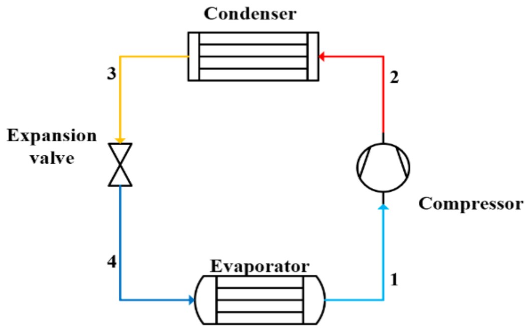
3.1. Single-Stage Vapour Compression Systems

The single-stage vapour compression system is widely used in refrigeration (Figure 1), covering most typical commercial and industrial applications, except ULT applications.
The wide choice of refrigerants, simplicity of the operation, and easy maintenance represent the advantages to its application. However, its applicability in the ULT region is limited. The pressure ratio is too high for the available compressor technology, leading to a limited system performance and lower volumetric capacity. Moreover, the refrigerant properties deteriorate when the compressor discharge temperature exceeds limits. The minimum temperature that can be achieved using single-stage vapour compression systems and pure refrigerant is −40 °C, depending on the condensing temperature. A further reduction would require operating under vacuum conditions for most refrigerants and increases the risk of air infiltration into the system and performance degradation. Alternatively, a low-NBP refrigerant would require a heat rejection at high pressure, increasing the compression work. Therefore, a single-stage system is not included in the numerical modelling comparison. However, a mixture of refrigerants can be used in a single-stage system to cool at very low temperatures, but at a performance cost [39]. The use of ejectors can provide significant cycle performance improvements, which can be from 16 to 20% higher than the normal cycle (Figure 1) [40,41]. The COP can also be enhanced by up to 20% using a sub-cooler and suction gas heat exchanger [42].

3.2. Multi-Stage Refrigeration Systems

A multi-stage refrigeration system, represented in Figure 2, is usually the solution to limit the high-temperature difference between the condenser and the evaporator encountered when using a single-stage refrigeration system. The two-stage system allows for reaching lower evaporation temperatures, with a COP improvement of around 8% compared to a single-stage system [43]. The system operates with a single refrigerant with one cooling cycle at two different pressure levels connected through a separator.
A phase separator cools the refrigerant between the two compression stages, reducing its compression losses (increasing its compression efficiency). It also ensures that the vapours are directed into the suction of the HT compressor, and that only liquid is flowing towards the second expansion. A two-stage system can use several configurations, each giving a different performance output. Jiang et al. (2015) [44] and Torrella et al. (2011) [8] discuss the various optimised two-stage configurations and their performances. In the present study, a two-stage cycle with a phase separator [28] for nitrous oxide, carbon dioxide, and ammonia was studied (Figure 2). However, special attention was given to the ammonia system because of the challenges associated with high compression discharge temperatures.

3.3. Cascade Refrigeration Systems

This system is one of the most common technologies used to produce cooling and heating. A cascade refrigeration unit (Figure 3) consists of two separate circuits, a high-temperature cycle (HTC) and a low-temperature cycle (LTC), connected through a cascade heat exchanger, which acts as a condenser for the LTC and as an evaporator for the HTC [45]. The two cycles can apply the same or different refrigerants for an improved system performance. The HTC ensures an evaporating temperature as low as −30 °C, while the LTC can achieve an evaporating temperature lower than −80 °C. Several cascade configurations have been investigated by Singh et al. (2020) [13], Pan et al. (2020) [12], and Udroiu et al. (2023) [14]. The CRS produces a higher efficiency than the MRS. An ejector expansion CRS is the best option, and the inclusion of an ejector in the transcritical R744 cycle results in a performance enhancement of 38% compared to the same system without an ejector [14]. The oil-handling system in the CRS is simpler than in the MRS, as both cycles in the CRS have independent oil management systems.
Pure refrigerants have limitations, like poor performances at ULTs, and mixed refrigerants are an alternative to improve the performance and overcome such issues. Azeotropic refrigerants are an acceptable solution for ULT refrigeration for a better performance compared to pure refrigerants [12]. In recent years, there has also been considerable interest in using refrigerant mixtures in the LTC to reduce the risk of the flammability or toxicity of some pure refrigerants (i.e., HCs).

3.4. Auto-Cascade Refrigeration Systems

The auto-cascade system employs mixed refrigerants with different NBPs. These systems are driven by a single-stage compressor and can achieve very low temperatures (from −200 °C to −40 °C) [46] with pressure ratios from 5 to 21 [16,47], without excessive discharge temperatures. The refrigerant mixture is an important parameter influencing the system performance, including the efficiency of the heat exchanger and the compressor pressure ratio. Several research studies have been performed on binary refrigerant mixtures for ULTs. Applying a binary refrigerant mixture in an auto-cascade system is an attractive solution, as it is characterised by a lower cost and simpler construction due to there being only one compressor. Yan et al. (2015) [16] reported a COP improvement of 7.8–13.3% for the zeotropic mixture of R290/R600a at an evaporation temperature of −28 °C compared to the domestic refrigerator freezer. Bai et al. (2018) [48] investigated R134a/R23 in an ejector-enhanced auto-cascade system for an evaporation temperature of −50 °C and reported a COP of 9.6% more than the conventional auto-cascade system of Figure 4. Recently, Liu et al. (2022) [49] proposed another configuration of the auto-cascade system with the mixture R290/R170 and reported a 42.85% higher COP than the typical auto-cascade refrigeration cycle (Figure 4).
An auto-cascade refrigeration system is represented in Figure 4. The vapour mixture is first compressed (1–2) and is then directed to the condenser to reject heat (2–3). The heat sink temperature should be selected properly in the condenser to avoid a pinch point due to temperature glide. Only the refrigerant with the highest NBP condenses as it flows through the condenser. At the condenser outlet, the refrigerant mixture flows through a separator where the high (liquid) NBP is separated from the low (vapour) NBP. The high NBP is expanded (4–5) through the expansion valve to the operating pressure of the cascade condenser. Its temperature increases while exchanging heat with the low-NBP refrigerant. The low-NBP refrigerant is then condensed (7–8) and flows through the evaporator, providing the required refrigeration effect (9–10). However, in real systems, it is not possible to completely separate the pure refrigerants in the condenser because some of the low-NBP refrigerant condenses and some of the high-NBP refrigerant leaves the condenser in vapour form. The phase separation process significantly impacts the system’s performance. It should be carefully handled to guarantee the required refrigerant mixture concentration in the appropriate parts of the system. [31,41]. The compressor isentropic efficiency equation used for auto-cascade investigation is adapted from Yan et al. (2015) [16].

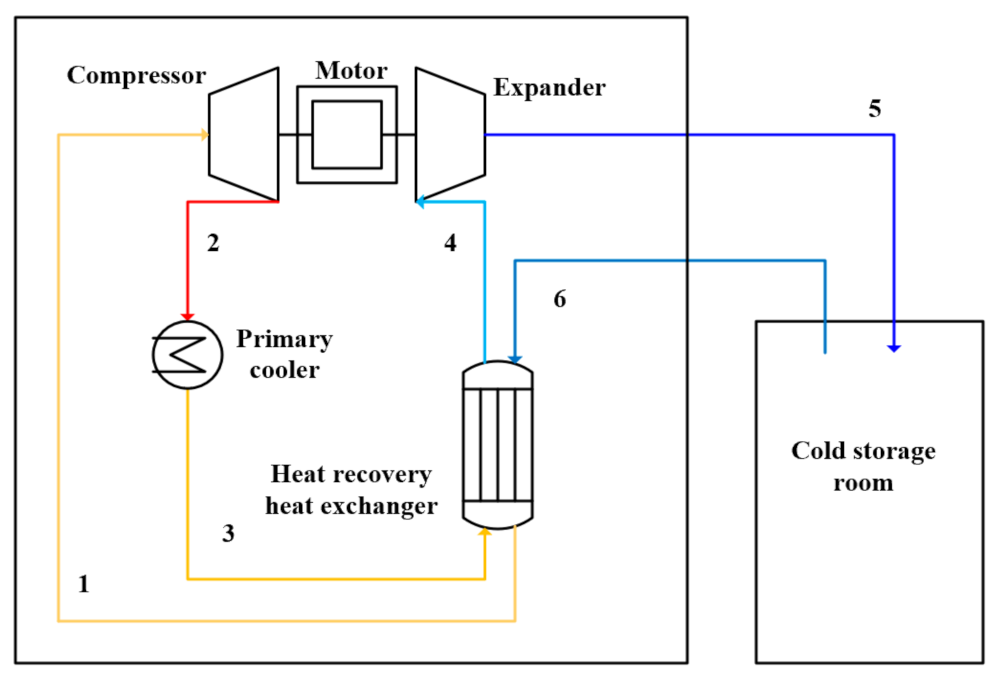
3.5. Air Refrigeration Cycle

An air refrigeration cycle consists of four processes: two isentropic processes (i.e., compression and expansion) and two isobaric processes (i.e., cooling and heating). The refrigeration unit is described in Figure 5. It comprises three main parts: an integrated turbo compressor and expander, a primary cooler, and a cold recovery heat exchanger. The combined turbo compressor–expander is connected in the same shaft through a motor. The work generated by the expander is used as an auxiliary power input to the compressor, achieving energy savings.
Moreover, the refrigerant does not need to be refilled or recovered. Thus, the maintenance costs are reduced [32]. The air from the cold-storage room is compressed (1–2) and then cooled down (2–3) in the primary cooler by air or water. The energy is then recovered in the heat recovery heat exchanger, where the warmer air heats the intake air (1) and, consequently, the air cools down further (3–4). The air is then expanded (4–5) and sent to the cold-storage room, where it is taken in, and the cycle starts again.
Air is used as the working fluid. The use of these systems represents an attractive solution for refrigeration operators. Using air as the working fluid in an open arrangement, the air of the space to be cooled can be used directly in the cycle to avoid the installation of evaporators, air coolers, and fans and thus avoid additional exergy losses in such heat exchangers. Because there is no secondary refrigerant, defrost cycles are not required, and the pipe dimensions are drastically reduced. This can reduce power usage by up to 40% compared to the CRC [26]. Very limited literature is available on the ARC, and it is reported in the Introduction section.
The COP is extremely sensitive to the machine’s efficiencies. The thermal performance of the air cycle is improved when applying cold storage at low temperatures, which makes the air a suitable working fluid at very low temperatures (down to −100 °C), which outperforms traditional refrigeration systems. It should be noted that, as the system operates at low temperatures (from −60 to −100 °C), the formation of ice due to humidity could affect the system’s performance. Therefore, it is necessary to install a humidity extraction device inside the refrigerating chamber to reduce the humidity ratio.

4. Performance Analysis of the Different ULT Refrigeration System Configurations for Various Applications

In this study, different scenarios were investigated, focusing mainly on three aspects: the temperature requirements, reliability of the system, and system performance. Different applications operating at temperature levels ranging from −80 to 0 °C were explored (Table 3), including detector-cooling technology; fish processing, including the freezing and storage processes for different types of fish; medicine and biomedical applications; and the pre-stage cooling process of the liquefaction of LNG. In this study, the food-freezing and storage processes are related to the different types of fish caught on board ships, as the temperature requirements are within the investigated ULT range.
Thermodynamic analysis of different configurations was performed for the energy analysis. The numerical models were also validated with the existing literature. Figure 6 presents a classification of the different types of systems according to their operating temperature ranges. It can be seen that the ACR system and CRS are commonly applied in ULT applications ranging from −40 to −80 °C. The VRC and MRS are those applied in the range from 0 to −50 °C.
The COPs of systems operating in the temperature range of from −40 to −80 °C were analysed for the MRS, CRS, ACR, and ARC. The general assumptions for the numerical models are listed below:
  • The heat losses and pressure drops in the pipes and system components are neglected;
  • Steady-state and steady-flow processes are assumed in all components;
  • Heat leakages to the external environment are neglected;
  • Expansion processes are treated as isenthalpic;
  • The power consumption of the pumps is neglected;
  • The compressors are non-isentropic, and their efficiencies are expressed as a function of the pressure ratio;
  • No superheating or subcooling, and saturated conditions at the heat exchanger outlet;
  • The temperature difference in the cascade heat exchanger (CHX) is set to 5 K.

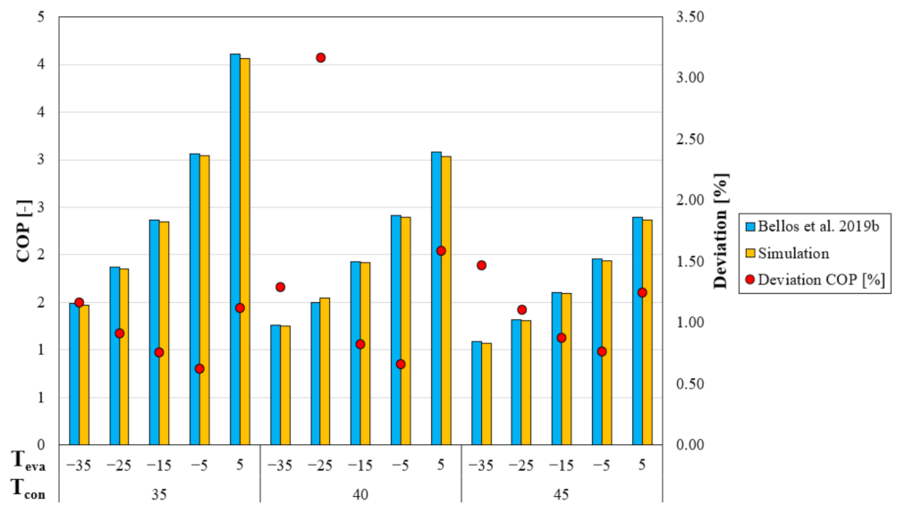
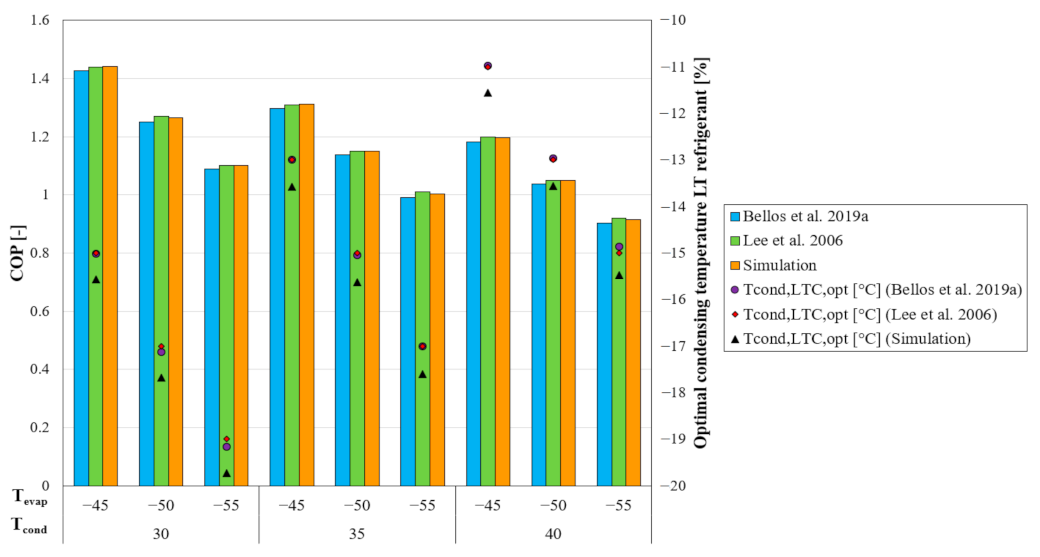
4.1. Model Validation

In this sub-section, the thermodynamic models simulated in EES are validated using the data published by Bellos et al. (2019a) [50] and Lee et al. (2016) [29] for the CRS and by Bellos et al. (2019b) [51] for the MRS with the same compressor efficiency equations. For the MRS operating with R744, a double optimisation (intermediate and high pressure) was performed to obtain the highest COP. The system energy efficiency strongly depends on the intermediate and high pressure (transcritical conditions). The obtained COPs are shown in Figure 7. These are in good agreement with those obtained by Bellos et al. (2019b) [51]. The highest COP deviation is recorded to be around 3%, and the lowest is around 0.6%. Regarding the CRS design, the validation was only performed for R717/R744 (Figure 8).
As described in [52], the correlations for the isentropic efficiency of the HT and LT compressors should be determined as accurately as possible, as they all strongly influence the maximum COP and optimal condensing temperature of the LTC. This is understandable, considering the logic behind the optimisation process. The highest COP value is inversely proportional to the total power consumption, which is directly influenced by the isentropic efficiency of the HT and LT compressors. The calculation program uses the pressure ratio values in both cycles with the highest possible efficiencies, impacting the optimal condensing temperature.

4.2. Fish Freezing of Mackerel and Cod

A brief overview of the onboard freezing systems is presented. There are many possible system architectures for the process applications, and centralised or independent systems may fulfil their needs. Usually, a larger vessel tends to have a centralised system that serves all the refrigeration demands (RSW, cooling, and freezing). Refrigerated seawater (RSW) is used for chilling fish before it is processed or frozen. Here, focusing only on the freezing process, the choice of the refrigerant and freezing system strongly depends on two factors: Firstly, it must conform to the national regulations and insurance requirements for fishing vessels. Many countries do not allow toxic refrigerants such as ammonia in storage, for instance. The second factor is the type and size of the fish species to be frozen. An additional factor would be the quality target of the food, which is generally described through the freezing time, as will be highlighted later. All the other additional requirements are reported in the article [53]. Three large families of refrigerating systems are considered here:
  • Air blast freezers, which are generally small rooms or tunnels where cold air is blown to freeze the whole fish. Air-cooling coils cool the air;
  • Plate freezers, which are typically used for small fish sizes. These consist of hollow plates cooled by refrigerant evaporating inside them, ensuring good contact between the cold surface of the plate and the food. Contrary to air blast freezers, they can only be used to freeze regular-shaped blocks of fish;
  • Brine immersion freezing, which can use liquid nitrogen or liquid CO2 and is usually used to quickly freeze a tremendous number of fish by spraying or dipping the fish in the liquid. As a result, the fish quickly cool down to lower temperatures. Extra care is required to protect the fish surface from thermal cracking [54].
The choice of one of the systems presented above depends on the amount and size of the fish and the space available on board. Furthermore, although R-22 is still the dominant refrigerant in marine offshore refrigerated vessels [55], ammonia and carbon dioxide have begun to enter the fishing refrigeration market. Ammonia is the refrigerant choice for modern, environmentally friendly refrigeration systems across the cold fisheries in Europe. With the increased restrictive measures aimed at the safety on board, and the lower temperatures required, R717 is also applied with R744 in indirect and cascade systems in new refrigerated ships. The cases investigated are listed below in Table 4, in which the condenser is assumed to be cooled with seawater, and the target temperature for freezing is set to −30 °C.
The design temperature of the plate freezers/air blast freezers should be related to the temperature of the cold-storage room to which the product is transferred after freezing. It is worth remembering that below −33 °C, the ammonia refrigeration plant is working under sub-atmospheric conditions, as already declared in Section 2.1, and a VRC would be infeasible due to the high discharge temperature at the compressor outlet.
Figure 9 illustrates the COPs of the systems presented above. The COP cannot be the only criterion for the selection of the refrigeration unit.
The freezing time is one of the most important aspects to account for during the design of an onboard refrigeration system. The colder the freezer, the faster the fish will freeze; however, the cost of the freezing unit increases as the freezing temperature decreases. Different factors can be observed. The MRS simulated operating with ammonia works in sub-atmospheric conditions, with related concerns about the non-condensable build-up and moisture infiltrations due to vacuum leakages. In addition to this, the temperature difference between the air and fish can only be reduced by increasing the air velocity to freeze the products fast. However, this measure and a reduction in the air temperature harm the efficiency. Evaporating temperatures for R717 systems are seldom lower than −35 °C.
Regarding plate freezers, without considering the dependence of the freezing time on the food water content and thickness of the product, faster freezing can be achieved by using R744 or R744A as the working fluid. The lower NBP of CO2 allows for reducing the evaporating temperature, while its environmentally friendly properties agree with the heat transfer process occurring through direct contact between the fish surface and refrigerant plates. The investigation of R744A is purely theoretical, as possible exothermal decomposition calls for safety devices and intensive refrigerant charge monitoring [6]. From a COP point of view, an increment of about 8% can be recorded independently using the HT refrigerant. In real applications, R717 refrigeration systems suffer from a high discharge temperature at the compressor’s discharge. Therefore, the CRS can be used under some operating conditions if the system works far away from the optimal condensing temperature of the LTC. Additional considerations can be made: the CRS with R744 as the LT refrigerant has different advantages over the MRS operating with R717 [53], such as follows:
  • A much higher volumetric refrigeration capacity;
  • It always works with positive pressure above the atmospheric one;
  • The use of R744 allows for the design of the HTC with a reduced refrigerant charge and, consequently, with a reduction in the costs related to the safety management process;
  • Flammable or toxic refrigerants can be used in the primary circuit isolated from the cooling process and storage areas, aiding safety.

4.3. Storage of Mackerel and Cod

As described above, fast freezing to ensure a high-quality product and an environmentally friendly solution are the primary targets for onboard freezing and storage systems. Therefore, considering the freezing target temperature as the temperature at which the products must be stored, the following cases were evaluated (Table 5).
In most low-temperature applications, an R744 cascade system would be able to fill the bill, if the local health and safety regulations influence the use of R717. In that case, secondary refrigerants, such as R744, which may satisfy the regulations with a lower risk of leakage, are necessary. Here, the flammable or toxic refrigerant is isolated to the machine room. R744, a volatile secondary refrigerant, is cost-effective thanks to the reduced pumping and pipework costs. If a secondary fluid, and therefore a heat exchanger, is involved, an additional temperature difference is required to allow heat transfer in the evaporator and to compensate for the pressure losses on the secondary loop [56]. In this simulation, the target temperature is too low to use an R717 indirect system because of the sub-atmospheric pressure. Only five systems with different heat-rejecting temperatures were investigated.
On board, once the fish is caught and frozen, it is stored through the MRS or CRS and transported to the onshore storage system. The thermodynamic analysis reported the following results for condensing temperatures of 15 and 40 °C, as the intermediate cases at 25 and 30 °C reflect the same trend (Figure 10).
As is already well known, when the temperature difference between the condenser and evaporator increases, the COP of the MRS is strongly penalised by the adoption of one single refrigerant. Vice versa, the CRS obtains a higher COP compared to the MRS, as widely stated in the literature [57]. As described by Mumanachit et al. (2012) [28], the MRS presents a higher system efficiency at higher evaporating temperatures, while the CRS is more efficient at lower evaporating temperatures. The MRS operating with R717 degrades the COP more rapidly than the CRS because of the high vapour-specific volume. In comparison, the MRS with R744 is strongly influenced by the throttling losses that occur at high heat rejection temperatures and thus becomes uncompetitive with the CRS in terms of high condensing temperatures. The adoption of R717 as the HT refrigerant in the CRS is considered one of the best options thanks to its superior thermodynamic properties compared to traditional refrigerants, among them the high latent heat of the vaporisation. As for the freezing processes, using the optimal condensing temperature of the LTC leads to an excessive pressure ratio and, therefore, too-high discharge temperatures, making this layout infeasible in warmer climates. Using R744 in the HTC would lead to the worst performance compared to any other refrigerant [50] because of the transcritical operating conditions. Therefore, R290 could be a valid option, considering its confinement in the machine room, critical temperature, and molecular weight, which would induce a much lower liquid curve slope than R717.
Different considerations are made for the ARC: a water-cooled heat exchanger (primary cooler) is used to decrease the compressor outlet’s discharge temperature, resulting in a system independent of the external ambient air, being the heat losses neglected. Based on these points, only one COP value is calculated for a given cold-storage temperature. The further assumptions used for the calculations are listed below (according to Figure 5):
  • The PAS-30R is used as a design reference for the simulations [32];
  • The temperature at the primary cooler outlet is set to 40 °C;
  • The turbine and compressor have the same efficiency, which is set to 0.76;
  • The effectiveness of the recuperative heat exchanger is equal to 0.95;
  • The high-pressure limit in the system is set to 2 bar;
  • The circulating air is assumed to be dry;
  • There is no air leakage from the system.

4.4. Fish Freezing of Tuna

The high-quality target for the consumption of raw tuna requires very low cooling and storage temperatures, namely in the range of from −50 to −70 °C. This temperature range does not allow any MRS to work with pure fluids; therefore, a suitable mixture should be found. Blends of R744 and HCs have been studied in the literature [58], and they have become very attractive from several points of view. The triple point of R744 holds back its use as an ultra-low-temperature refrigerant in the CRS. Pure refrigerants such as R170, R1150, and R744A are the only options available. R744A has not been deeply studied, and safety issues could occur, while R170 and R1150 are flammable refrigerants, and thus their implementation requires additional safety measures. Furthermore, the freezing process of tuna occurs after a pre-cooling process, and it usually starts around −20/−30 °C. Consequently, azeotropic and zeotropic mixtures with small temperature glides could match the needs very well. The different refrigerant pairs and mixtures investigated are listed below in Table 6 for a target freezing temperature of −60 °C.
Figure 11 illustrates the COPs of the different refrigerant pairs used in a CRS. The use of R744 in the HTC is attractive from the environmental point of view, but in terms of the COP, it is inefficient compared to the other systems, as shown in the freezing process of mackerel. This discrepancy between R744 and HCs increases as the evaporating temperature decreases. R717 is still the best fluid for the HTC, but, in real applications, it would require working far away from the optimal point because of the excessively high discharge temperature (Figure 12), which is limited to 120 degrees [1]. It can be seen that the lower the NBP of the LT refrigerant considering the same HT refrigerant (Table 1 and Table 2), the lower its optimal condensing temperature and the higher the pressure ratio.
After this consideration, the most performant cycles are the CRS with R1270 and R290 as the HT refrigerants and R170 and R1150 as the LT refrigerants. Similar COPs can be recorded using nitrous oxide in the LT stage, but this requires further studies on its stability when it is used as a working fluid in refrigeration systems. Considerable interest should be given to mixtures of R744 + R744A, which have very good volumetric refrigeration capacities and are almost climate-neutral. As stated by Kauffeld et al. (2020) [59], an alternative to the HFC substances or flammable mixtures used in applications below −50 °C has been found, and it is already in an advanced study stage. The mixtures simulated containing R744 and HCs (R170 and R1150) would lead to a worse performance compared to their pure counterparts. However, they can achieve non-flammability as long as the mass fraction of R744 is sufficient enough and does not vary throughout the cycle compared to the initially charged concentration. The exceptionally low temperatures used in these freezers (from about −60 to −70 °C) have increased the special precautions to be taken in fishing vessels.

4.5. Storage of Tuna

The same considerations presented above regarding the refrigerants employable in the CRS are valid for the storage process of tuna, except that PAS is an alternative and more environmentally friendly solution. Table 7 summarises the systems analysed, with a target storage temperature of −60 °C.
The option of having R717 as an HT refrigerant has not been considered, as the temperature difference between the condenser and evaporator leads to excessively high discharge temperatures at the compressor outlet. However, R717 may be an interesting option in some cases, such as in the cold chain, after the freezing process, and in the transportation of food to the warehouse. If the size of the warehouse is small enough to be confined in a larger room, then its external temperature can be reduced by using a traditional refrigeration system, minimising the losses and increasing the energy performance of the refrigeration unit by decreasing the rejecting heat temperature on the HTC. However, the total costs will rise while the total energy efficiency will be reduced due to the additional refrigeration unit needed to pre-cool the room. Considering a warehouse in which the operating refrigeration unit rejects heat to the external environment, Figure 13 allows for the identification of the most promising refrigerant pair.
Once again, the inefficiency of using R744 as an HT refrigerant has been proven (Figure 13). The best refrigerant pairs are R290/R170 and R1270/R170 (even though R290 does not change the COP).
The use of a CRS for the offshore storage of tuna is encouraged, while the use of ARC is encouraged for onshore storage because of all its relative advantages. Dry ice is frequently used for transportation to the onshore warehouse, but with a relative time limit, which depends on the stored products’ temperature level and quality target.
From the numerical simulation, the COP of the ARC is much lower than the COP in a CRS, even with a condensing temperature of 40 degrees. The discrepancy between the simulation results and the data available in the literature [60] will be discussed later (Section 5).

4.6. Vaccine Storage/Medical Applications

Most traditional vaccines can be stored in standard refrigerators within a temperature range of from +2 to +8 °C. Storing enzymes, vaccines, or pharmaceutical products requires a temperature of −20 °C, while some vaccines are stored between −50 and −15 °C. The BNT162b2 (COVID-19) and Ervebo (Ebola) vaccines need to be stored at a temperature below −50 °C, ensuring their stability, efficacy, and safety all along the cold-chain terrain. The Pfizer vaccine, for instance, is stored at a temperature of −70 °C [61]. Currently, the most energy-efficient freezers use hydrocarbon refrigerants, such as R170 and R290. These units are popular in the European pharmacy industry but unavailable in other countries due to regulatory restrictions. Different systems have been analysed depending on the number of vaccines to be stored, such as the ACR system, CRS, and ARC.
Furthermore, the freezer location affects the lifetime and efficiency of the ULT freezer, namely the heat rejection temperature. When ULT freezers cannot meet the space requirements, an air-cooled condenser must be replaced with a water-cooled condenser. As stated by some manufacturers, such as Intarcon and PHCBI, the operator must follow a procedure for correctly preserving the vaccines. The refrigeration unit works in a cold room at around −20 °C, where the operator always works safely to insert the products in or remove them from the ULT freezers. The pre-cooling of the cold room minimises the losses and avoids humid-air infiltrations into the cabinet. This principle is applied depending on the location, climate, and cost analysis. For developed countries located in warmer climates, the ULT freezers work by rejecting the heat to the external ambient air, and therefore a degradation of the COP occurs. This degradation appears even in ULT freezers placed in pre-cooled rooms. The additional costs for the refrigeration unit aimed at the pre-cooling and its energy consumption could lead to a deterioration in the overall COP. Contrarily, in the opposite case, a well-insulated chamber/freezer must be designed to avoid excessive energy losses and relatively high energy consumption.
Small-sized refrigerators with cooling capacities below 1 kW typically use ACR. Recently, its use has drawn considerable interest because of its simpler structure and, by using a zeotropic mixture, it could realise one-stage compression. The CRS and ARC are viable options for larger cooling capacities (for instance, storing some containers containing vaccines). The ARC draws much attention at this temperature level thanks to its significant advantages compared to the conventional CRS. Table 8 summarises the cases investigated.
The compositions of all the mixtures are adopted in such a way as to avoid sub-atmospheric conditions. The composition of the first refrigerant of all the mixtures in Table 8 is 0.8, except R1150/R290, which is 0.7. The vapour quality after the condenser was fixed to 0.4 and high pressure is the consequence of the vapour fraction. A higher vapour fraction after the condenser will reduce the pressure ratio, and a lower vapour fraction will increase the pressure ratio. As the zeotropic mixtures exhibit temperature glide, lower evaporation temperatures are necessary compared to other cases. The COPs of the auto-cascade cycle with different refrigerant mixtures are shown in Figure 14.
The COP is competitive with other systems, but the pressure ratio and temperature after the compressor are high, which can hinder the implementation of this system in some cases. However, modifications with a recuperator, an ejector, and an additional expansion valve were investigated by Yan et al. (2018) [62] to improve the pressure ratio and COP. They concluded that, by adopting the modifications, proposed ACR units could solve the challenges of small low-temperature storage.
For larger cooling capacities, Figure 15 shows the COP values for the CRSs investigated and the ARC. The use of HCs as HT refrigerants still leads to the best performance. Using mixtures in the LTC reduces the risks related to the flammability limits of such refrigerants but attains a lower performance. The use of zeotropic mixtures does not imply an increase in efficiency, and the reason is two-fold. First, the area between the two temperature profiles is representative of the losses. The exergy losses during the heat transfer can be reduced whenever a secondary fluid is cooled down. Second, because superheating is required in real applications to ensure that no liquid bubbles at the compressor suction port, if the glide temperature is too large, then the temperature profile is lifted and requires additional work for the compressors.
Furthermore, additional considerations can be drawn. The temperature difference required for having a heat transfer induces a change in the composition of a zeotropic mixture. The extra temperature difference associated with the difference in the concentration decreases the total heat transfer coefficient compared to a pure fluid. Resistance to mass transfer, which implies a resistance to heat transfer, is present due to the different compositions in the liquid and vapour bubbles.
Regarding the cases investigated, using a zeotropic mixture, such as R744 + R170, may present some issues in real applications: The choice of the R744 concentration must satisfy the need to minimise the flammability risk while working above the triple point. An oscillation of the evaporating pressure can cause the formation of solid particles to impact the refrigerant flow and the heat transfer performance.
In warmer climates and at low storage temperatures, the ARC is becoming competitive with CRSs. The presence of recuperative heat exchangers is fundamental. Having the maximum allowable pressure at 2 bar, the recuperative heat exchanger achieves lower temperatures in the cold-storage room for a given pressure ratio by pre-cooling the air at point 6 thanks to the relatively cold air taken from the room (point 5, Figure 5)

4.7. Gas Pre-Cooling

Liquefied natural gas (LNG) is a liquid state of natural gas around −162 °C under atmospheric pressure and temperature. LNG has a volume 600 times smaller than gas under normal conditions, allowing enormous volumes of it to be carried by ships [63]. In the pre-cooling stage of LNG, the natural gas is cooled to a temperature ranging from −30 °C to −50 °C or even lower, depending on the pre-cooling method used. The outlet temperature of the pre-cooling stage is a critical design parameter influenced by technological and strategic factors [64]. The choice of technology is a consequence of many factors, including economic, environmental, financial, licensing, and technical concerns [63]. The scope of this part is dependent on the COP analysis of the cascade system because most of the economic data on liquefaction units are treated as confidential. Natural gas is cooled down in several processes, such as pre-cooling, liquefaction, and subcooling, for the method based on more than one refrigerant cycle [64]. Figure 16 shows the temperature glides of different zeotropic refrigerant mixtures at constant pressure, which was used for analysis.
The highest glide is with R1150/R600 and the lowest is with R170/R290. The temperature glides can be adjusted according to the requirements of the gas-processing unit by altering their compositions. The cascade system with mixtures can reduce the multiple pressure levels for cooling and improve the efficiency by matching the temperature glide. The cascade cycle with mixtures can reduce the existing one cycle of three-stage processes. Two refrigerants (R717 and R290) were investigated for the HTC with a condensing temperature of 15 °C (Figure 17). The pressure ratio and temperature after compression are within their allowable range. For the HTC, R290 possesses more potential due to its better pressure ratio and temperature after compression. For the LTC, the evaporation temperature was kept at −80 °C for all cases. The highest COP is represented by the R170/R600 mixture, but the temperature glide is less than that of R1150/R600. In comparison, the cases with propane have 4.5% higher COPs than R717. In addition, the cascade system with mixtures can also be used for the liquefaction of other gases (e.g., CO2).

4.8. Detector Cooling

The Large Hadron Collider (LHC) detectors at CERN in Switzerland need to dissipate several hundred kilowatts of heat (300–600 kW). Therefore, a refrigeration system is needed, which cools down these detectors and keeps them below a temperature of −40 °C, leading to evaporation temperatures below −50 °C. Because the detectors are worth around NOK 1 billion, reliability and stability in the cooling are crucial, but the COP of the system is not. Furthermore, the detectors are highly sensitive, requiring an oil-free configuration. In this case, a cascade system is needed, which consists of a high-pressure side operating with piston compressors and an oil-free low-pressure loop on the evaporation side. The primary booster system is mainly located on the surface, providing the cooling for the oil-free cycle in the cavern 100 m underground, consisting of evaporators. The secondary loop circulates the refrigerant through the evaporators inside the detectors [65]. The space in the cavern is limited, and radiation occurs, making R744 an appropriate refrigerant on both the low- and high-pressure sides. Flammable refrigerants are not suitable, and neither are their mixtures. Radiation occurs in the machine rooms, resulting in another requirement regarding the refrigerant choice. The ARC is not appropriate due to its space requirement, for instance. Moreover, due to the large cooling load, many machines in parallel would be involved, lowering the total system efficiency.

5. Further Considerations Regarding Storage Applications

Different products, such as food, antibiotics, and vaccines, require storage at different temperature levels. The temperature level and the constraints related to the product’s storage indicate the most suitable system. However, further considerations must be made to assess the feasibility under certain operating conditions. An excessive discharge temperature at the compressor outlet, unachievable pressure ratio levels, and safety concerns are examples of those aspects that need to be controlled in real applications. This would change the results of the numerical analysis. Figure 18 illustrates the COPs of the three most common technologies (the ARC, MRS, CRS) generally used in the low- and ultra-low temperature region for different warehouse temperatures under the following assumptions:
  • For the ARC, the assumptions previously presented are still valid;
  • For the MRS and CRS, the same assumptions are used as before;
  • The heat rejection temperature is set to 30 °C;
  • The optimisation procedure of the high-pressure (ARC), intermediate-pressure (MRS), and gas-cooler-pressure (R744) condensing temperatures of the LTC (CRS) has been carried out;
  • The temperature difference between the refrigerant evaporating and the air in the cold room is set to 5 K (MRS, CRS), while for the ARC, it is a result of the simulation;
  • For the MRS, the refrigerants R717 and R744 have been considered, while for the CRS, different refrigerant pairs were included in the simulation, such as R717/R744, R290/R744, R717/R170, R290/R170, and R290/R1150.
R717, as a low-temperature refrigerant, has proven that the issue related to its implementation is the sub-atmospheric pressure in the evaporator. Consequently, the MRS with R744 would be a much better option from a real application point of view. However, the COP would be much lower due to the transcritical condition of the cycle. Therefore, for a warehouse temperature in the region from −30 to −45 °C, a CRS would supply the cooling load more efficiently than an MRS without any constraints because the pressure ratio limit in both the upper and lower cycles is never exceeded. Because of the triple point of R744, its use as an LT refrigerant is a holdback in real applications for warehouse temperatures below −50 °C. As illustrated before, only a few refrigerants can match these temperature requirements, all belonging to the hydrocarbon family. Ethane and ethylene may match the requirements because of their NBPs. For the couple R717/R170, the optimisation procedure has been performed for warehouse temperatures until −85 °C. The optimisation process shows a decrease in the optimal condensing temperature of the LTC as the evaporating temperature drops, deteriorating the R717 compressor’s efficiency due to the relatively high compression ratio. The excellent thermodynamic properties of R717 cannot overcome the poor compressor efficiencies, and using R290 for low-evaporating-temperature storage is a better option.
Furthermore, in this specific case, the lower NBP of R290, with its thermodynamic features, is important for attaining good efficiencies. R1150 is the only pure refrigerant employed for deep storage temperatures in the LTC. In scenarios in which the evaporating temperature is below −95 °C, the optimisation procedure followed by the software would lead to infeasible pressure ratios in the low stage. Therefore, a different approach must be considered: the optimal condensing temperature of the LTC must be fixed as an input to maintain the pressure ratio below its upper limit.
It can be seen how the COP curve of the ARC is in agreement with the results of the report, while the COP curves of the CRS are quite different from those presented in the industrial report [60]. The reasons for this discrepancy can be found in several factors, including superheat at the suction port, a limited discharge temperature, pressure drops, the fan power, and a higher temperature difference in the heat exchangers. Figure 19 shows the superheating effect and the limited discharge temperature at the compressor outlet, which is set to 120 °C and should never be exceeded. The fan power is supposed to be 10% of the total power consumption.
Starting from the evaluation of the MRS, different aspects can be recorded:
  • For an MRS operating with R717, only for an evaporating temperature of −35 °C is the discharge temperature limit not exceeded;
  • For lower evaporating temperatures, the discharge temperature exceeds the limit, and therefore the optimal intermediate pressure obtained in the first simulation run is used as an input for subsequent simulations;
  • The assumption above is valid for a small temperature range in the warehouse, as seen in the shortened curve (green dotted line). This is mainly linked to the following consideration: Keeping the discharge temperature of the HT compressor under control causes a deterioration in the discharge temperature in the LT stage. The discharge temperature limit is exceeded in the LT stage;
  • For R744, the range of applicability remains unchanged, and only a deterioration in the COP has been noticed because of the negative effect of the superheat.
  • For the CRS, the following conclusions are drawn:
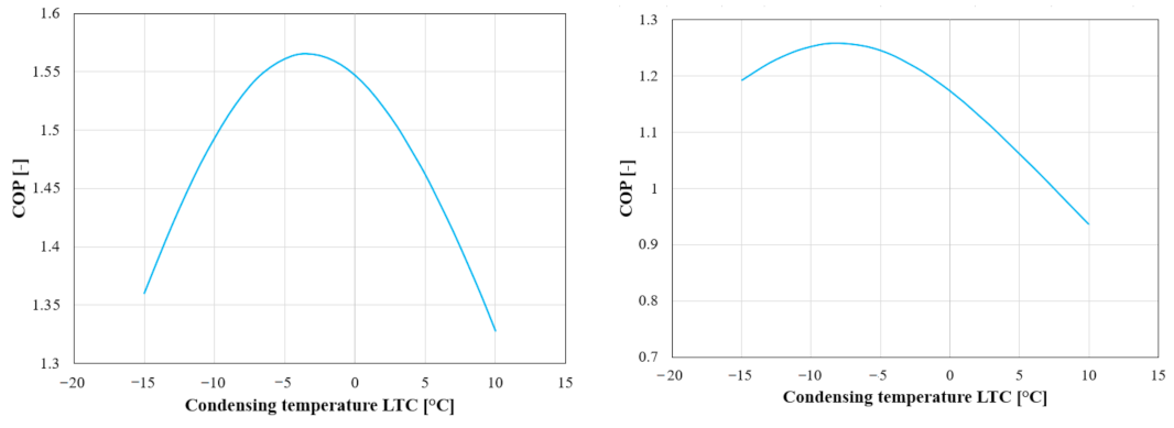
  • For the refrigerant pair R717/R744, one constant LT condensing temperature is used to limit the discharge temperature in the HTC. The superheat reduces the compressor’s capacity and increases the discharge temperature, reducing the COP (Figure 20) due to the constant condensing temperature in the LTC (around −1.4 °C). A decreased evaporating temperature results in a decreased optimal condensing temperature, implying a further deterioration in the energy performance;
  • For R290/R744, no issues have been recorded, promoting its implementation in the evaporating temperature region between −35 and −50 °C. It can also be noticed that the COP curve of the CRS working with the refrigerant pair R717/R744 starts to detach from the upper curve of R290/R744. This can be explained by the high energy losses that occur in the ammonia circuit. The superheating losses strongly influence R717, and therefore including the superheating induces a faster deterioration of the COP;
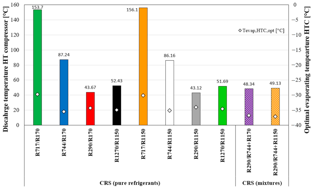
  • The optimisation procedure presents the same issues described above for the refrigerant pair R717/R170 used for storage purposes at lower temperatures. Thus, the condensing temperature has been defined to maintain the discharge temperature below the limit of 120 °C. Considering the superheating, the range of applicability of such a refrigerant pair is shortened, and where it can be used, the COP undergoes a sharp decrease. For lower evaporating temperatures (above the NBP of ethane), the use of R290 is recommended. Another choice may be an azeotropic mixture to attain the best heat transfer;
  • For the pair R290/R1150, the condensing temperature has been chosen according to the limit in the pressure ratio on both sides. At extremely low temperatures, the LTC shows a pressure ratio close to 12, and the compressor efficiencies are excessively low, leading to poor COP values. In this scenario, a CRS with a two-stage layout on the upper cycle can solve these issues, attaining better efficiency and promoting the system, even in warmer climates. The disadvantages are the investment costs and the additional heat exchangers involved in the system.
Figure 21 shows the COP curves for a superheat of 15 K: the increment in the superheating degree leads to a further reduction in the applicability region for the refrigerant pair R717/R170. Furthermore, the drop in the COP for the remaining pair of refrigerants is not so evident: the lack of an accurate set of equations for defining the isentropic efficiencies of the different types of compressors as a function of the refrigerant, cooling load, and temperature levels, as well as the superheating effect, would enlarge the discrepancy between the simulation results and the energy performance calculation coming from the experimental measurements. Therefore, it appears that the necessity of evaluating, as accurately as possible, those efficiencies in the analysis of the MRS and CRS is understandable.

6. Conclusions

In this paper, different refrigeration systems, namely single-stage compression, multi-stage compression, cascade, auto-cascade, and air refrigeration systems, are compared for various natural refrigerants, such as ammonia, carbon dioxide, nitrous oxide, air, propane, propylene, ethane, ethylene, as well as their mixtures in the ultra-low-temperature region. This comparison aims to find the system with the best performance in the required temperature range and application (namely freezing and storing cod/mackerel and tuna, vaccine storage, detector cooling, and the cooling of gas). The following conclusions are drawn in this work:
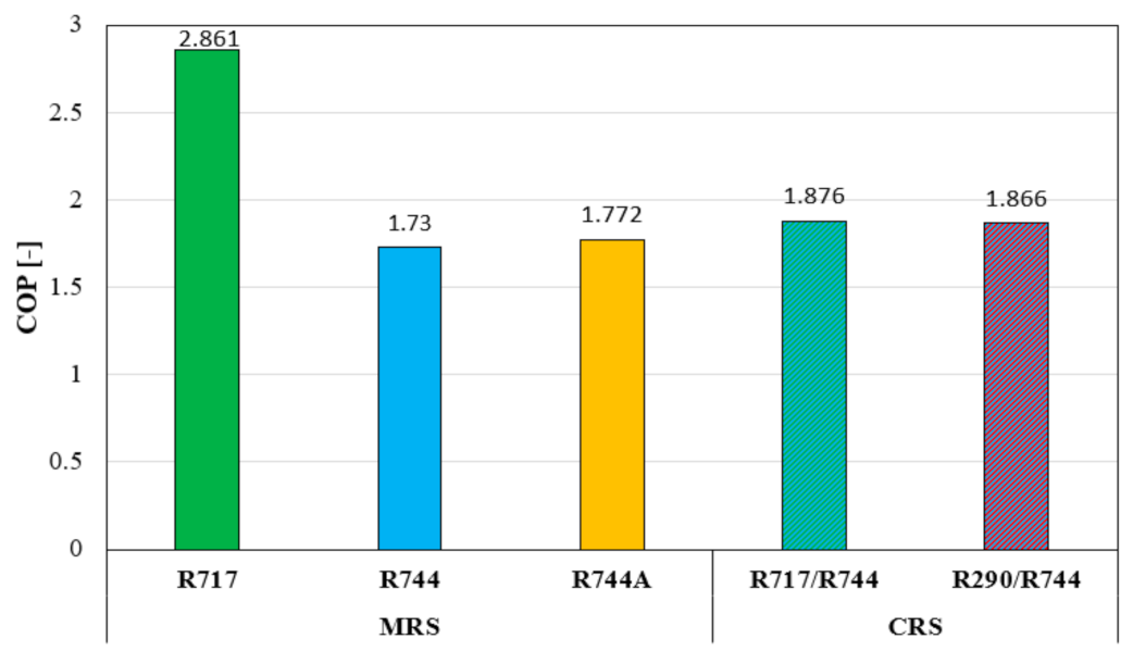
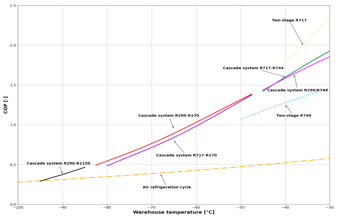
  • For freezing mackerel/cod from 0 to −40 °C, a CRS working with R717 in the HTC and R744 in the LTC (COP ~1.9) is suggested, considering the applicability;
  • For the onboard storage of cod/mackerel at −30 °C, an MRS or CRS is used. A good, non-flammable option is using a CRS with R717 in the HTC and R744 in the LTC with a COP of about 2.5 (a condensing temperature of 15 °C). An ARC was analysed, resulting in a COP of about 0.55. In this temperature area, ARCs are not competitive with other systems;
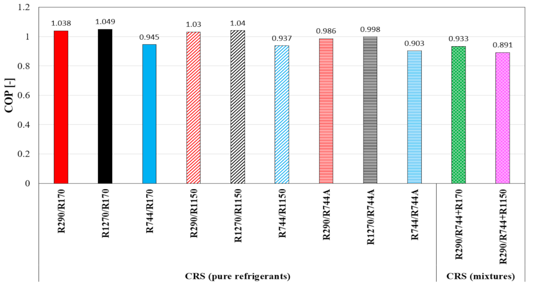
  • The CRS is the most efficient system for freezing tuna from −20 to −60 °C using HCs in both cycles (the HTC and LTC). R290 or R1270 for the HTC and R170 or R1150 for the LTC are the best-performing solutions, with COPs of about 1, also taking the discharge temperature of the HTC into account. Similar COPs can be recorded using R744a in the LT stage, but its use requires further studies on its stability. Great interest should be given to the R744 and R744A pair (COP ~0.9), which has a very good volumetric refrigeration capacity and is almost climate-neutral;
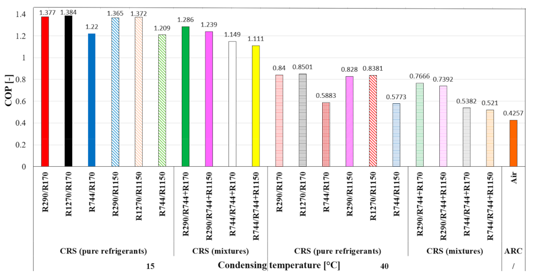
  • For storing tuna at −60 °C, a CRS with the refrigerant pair R1270 (HTC)/R170 (LTC) or R290 (HTC)/R170 (LTC) results in the best COP (COP ~1.4). A distinction is made whether it is on- or offshore storage that is needed. For onshore storage, the ARC is a good option (COP ~ 0.4). A CRS using R290 as the HTC refrigerant and R744/R1150 or R744/R170 as the LTC mixture gives a COP of 1.2/1.3. Using a mixture as the LTC refrigerant lowers the COP but shows beneficial properties, such as non-flammability, if the suitable composition is chosen;
  • Pfizer vaccines are stored at −70 °C. A CRS (large capacities) or ACR (small capacities) is used, depending on the required cooling capacity. An ARC is also very interesting for large capacities due to its significant advantages at this temperature level. At a warehouse temperature of −70 °C, the COP of an ARC is about 0.4;
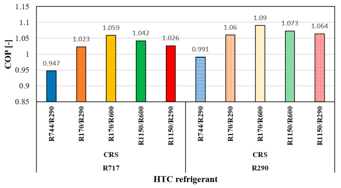
  • LNG pre-cooling is performed via a CRS using mixtures as refrigerants. The cascade system with mixtures can improve the efficiency by matching the temperature glides, which can be adjusted according to the requirements of the gas-processing unit by altering their compositions. The highest glide is achieved with R1150/R600, and the lowest is achieved with R170/R290. For the HTC, R290 possesses the best potential, and for the LTC, the highest COP is achieved with the R170/R600 mixture;
  • For the detector-cooling process, specific requirements, such as radiation, space limitation, and the absence of oil, are needed for the refrigerant and system configuration. This results in a CRS with R744 as a suitable refrigerant in both cycles;
  • The deep analysis conducted on storage applications revealed the importance of defining the real compressors’ efficiencies considering several aspects, such as the refrigerant, pressure ratio, and superheating degree at the suction port.

Author Contributions

Conceptualisation, M.Z.S., L.C., S.B., A.H. and T.M.E.; methodology, M.Z.S., L.C., S.B., A.H. and T.M.E.; formal analysis, M.Z.S., L.C. and S.B.; investigation, M.Z.S., L.C. and S.B.; writing—original draft preparation, M.Z.S., L.C. and S.B.; writing—review and editing, M.Z.S., L.C., S.B. and Y.A.; supervision, A.H., T.M.E. and Y.A.; project administration, A.H. and T.M.E.; funding acquisition, A.H. and T.M.E. All authors have read and agreed to the published version of the manuscript.

Funding

This research received funding from the Research Council of Norway (Project No. 308779 CruiZE and Project No. 257632 FME HighEFF).

Data Availability Statement

Not applicable.

Conflicts of Interest

The authors declare no conflict of interest.

Nomenclatures

ACRAuto-cascade refrigeration system
ARCAir refrigeration cycle
AREPAlternative Refrigerants Evaluation Program
ASHRAEAmerican Society of Heating, Refrigeration and Air-Conditioning Engineers
CAPEXCapital expenditure
CERNEuropean Organisation for Nuclear Research
CFCChlorofluorocarbon
CHXCascade heat exchanger
COPCoefficient of performance
condCondenser
CRSCascade refrigeration system
EESEngineering Equation Solver
EUEuropean Union
evapEvaporator
GWPGlobal warming potential
HCFCsHydrochlorofluorocarbons
HCsHydrocarbons
HFCsHydrofluorocarbons
HTHigh temperature
HTCHigh-temperature circuit
LHCLarge Hadron Collider
LNGLiquefied natural gas
LTLow temperature
LTCLow-temperature cycle
MRSMulti-stage refrigeration system
NBPNormal boiling point
ODPOzone depletion potential
PAGPolyalkylene
PAOPolyalphaolefin
POEPolyolester
RSWRefrigerated seawater
TTemperature (°C)
ULTUltra-low temperature
VRCVapor compression refrigeration system

References

  1. ASHRAE. Handbook-Refrigeration; American Society of Heating Refrigerating and Air-Conditioning Engineers: Atlanta, GA, USA, 2018. [Google Scholar]
  2. European Commission EU Legislation to Control F-Gases. Available online: https://climate.ec.europa.eu/eu-action/fluorinated-greenhouse-gases/eu-legislation-control-f-gases_en (accessed on 10 May 2021).
  3. European Environment Agency Hydrofluorocarbon Phase-Down in Europe. Available online: https://www.eea.europa.eu/ims/hydrofluorocarbon-phase-down-in-europe (accessed on 10 May 2021).
  4. Mota-Babiloni, A.; Mastani Joybari, M.; Navarro-Esbrí, J.; Mateu-Royo, C.; Barragán-Cervera, Á.; Amat-Albuixech, M.; Molés, F. Ultralow-temperature refrigeration systems: Configurations and refrigerants to reduce the environmental impact. Int. J. Refrig. 2020, 111, 147–158. [Google Scholar] [CrossRef]
  5. Sharma, V.; Fricke, B.; Bansal, P. Comparative analysis of various CO2 configurations in supermarket refrigeration systems. Int. J. Refrig. 2014, 46, 86–99. [Google Scholar] [CrossRef]
  6. Kruse, H.; Rüssmann, H. The natural fluid nitrous oxide—An option as substitute for low temperature synthetic refrigerants. Int. J. Refrig. 2006, 29, 799–806. [Google Scholar] [CrossRef]
  7. Rodríguez-Jara, E.Á.; Sánchez-de-la-Flor, F.J.; Expósito-Carrillo, J.A.; Salmerón-Lissén, J.M. Thermodynamic analysis of auto-cascade refrigeration cycles, with and without ejector, for ultra low temperature freezing using a mixture of refrigerants R600a and R1150. Appl. Therm. Eng. 2022, 200, 117598. [Google Scholar] [CrossRef]
  8. Torrella, E.; Larumbe, J.A.; Cabello, R.; Llopis, R.; Sanchez, D. A general methodology for energy comparison of intermediate configurations in two-stage vapour compression refrigeration systems. Energy 2011, 36, 4119–4124. [Google Scholar] [CrossRef]
  9. Baakeem, S.S.; Orfi, J.; Alabdulkarem, A. Optimization of a multistage vapor-compression refrigeration system for various refrigerants. Appl. Therm. Eng. 2018, 136, 84–96. [Google Scholar] [CrossRef]
  10. Cabello, R.; Torrella, E.; Llopis, R.; Sánchez, D. Comparative evaluation of the intermediate systems employed in two-stage refrigeration cycles driven by compound compressors. Energy 2010, 35, 1274–1280. [Google Scholar] [CrossRef]
  11. Agrawal, N.; Bhattacharyya, S. Studies on a two-stage transcritical carbon dioxide heat pump cycle with flash intercooling. Appl. Therm. Eng. 2007, 27, 299–305. [Google Scholar] [CrossRef]
  12. Pan, M.; Zhao, H.; Liang, D.; Zhu, Y.; Liang, Y.; Bao, G. A Review of the Cascade Refrigeration System. Energies 2020, 13, 2254. [Google Scholar] [CrossRef]
  13. Kumar Singh, K.; Kumar, R.; Gupta, A. Comparative energy, exergy and economic analysis of a cascade refrigeration system incorporated with flash tank (HTC) and a flash intercooler with indirect subcooler (LTC) using natural refrigerant couples. Sustain. Energy Technol. Assess. 2020, 39, 100716. [Google Scholar] [CrossRef]
  14. Udroiu, C.-M.; Mota-Babiloni, A.; Giménez-Prades, P.; Barragán-Cervera, Á.; Navarro-Esbrí, J. Thermodynamic evaluation of CO2 for ultra-low temperature refrigeration. Energy Convers. Manag. X 2023, 20, 100446. [Google Scholar] [CrossRef]
  15. Du, K.; Zhang, S.; Xu, W.; Niu, X. A study on the cycle characteristics of an auto-cascade refrigeration system. Exp. Therm. Fluid Sci. 2009, 33, 240–245. [Google Scholar] [CrossRef]
  16. Yan, G.; Hu, H.; Yu, J. Performance evaluation on an internal auto-cascade refrigeration cycle with mixture refrigerant R290/R600a. Appl. Therm. Eng. 2015, 75, 994–1000. [Google Scholar] [CrossRef]
  17. Hao, X.; Wang, L.; Wang, Z.; Tan, Y.; Yan, X. Hybrid auto-cascade refrigeration system coupled with a heat-driven ejector cooling cycle. Energy 2018, 161, 988–998. [Google Scholar] [CrossRef]
  18. Qin, Y.; Li, N.; Zhang, H.; Liu, B. Energy and exergy performance evaluation of a three-stage auto-cascade refrigeration system using low-GWP alternative refrigerants. Int. J. Refrig. 2021, 126, 66–75. [Google Scholar] [CrossRef]
  19. Aprea, C.; Maiorino, A. Autocascade refrigeration system: Experimental results in achieving ultra low temperature. Int. J. Energy Res. 2009, 33, 565–575. [Google Scholar] [CrossRef]
  20. Asgari, S.; Noorpoor, A.R.; Boyaghchi, F.A. Parametric assessment and multi-objective optimization of an internal auto-cascade refrigeration cycle based on advanced exergy and exergoeconomic concepts. Energy 2017, 125, 576–590. [Google Scholar] [CrossRef]
  21. Giannetti, N.; Milazzo, A. Thermodynamic analysis of regenerated air-cycle refrigeration in high and low pressure configuration. Int. J. Refrig. 2014, 40, 97–110. [Google Scholar] [CrossRef]
  22. Zhang, Z.; Liu, S.; Tian, L. Thermodynamic analysis of air cycle refrigeration system for Chinese train air conditioning. Syst. Eng. Procedia 2011, 1, 16–22. [Google Scholar] [CrossRef]
  23. Gigiel, A.; Giuliani, G.; Vitale, C.; Polonara, F. An open air cycle freezer. In Proceedings of the 7th IIR Gustav Lorentzen Conference on Natural Working Fluids, Trondheim, Norway, 29–31 May 2006; pp. 325–328. [Google Scholar]
  24. Kikuchi, S.; Dore, M.P. Epidemiology of Helicobacter pylori Infection. Helicobacter 2005, 10, 1–4. [Google Scholar] [CrossRef]
  25. Mirai Mirai Cold Products, Open and Closed Cycle for Air Refrigeration. Available online: https://mirai-intex.com/products (accessed on 8 September 2021).
  26. Mayekawa Ultra-Low Temperature Air Refrigeration System Pascal-Air. Available online: https://www.mayekawa.com.au/products/pascal-air/ (accessed on 8 September 2021).
  27. Klein, S.A. Engineering Equation Solver (EES), F-Chart Software, Madison, USA. Available online: https://fchartsoftware.com/ees/index.php/ (accessed on 7 April 2021).
  28. Mumanachit, P.; Reindl, D.T.; Nellis, G.F. Comparative analysis of low temperature industrial refrigeration systems. Int. J. Refrig. 2012, 35, 1208–1221. [Google Scholar] [CrossRef]
  29. Lee, T.-S.; Liu, C.-H.; Chen, T.-W. Thermodynamic analysis of optimal condensing temperature of cascade-condenser in CO2/NH3 cascade refrigeration systems. Int. J. Refrig. 2006, 29, 1100–1108. [Google Scholar] [CrossRef]
  30. Niu, X.-D.; Yamaguchi, H.; Iwamoto, Y.; Nekså, P. Experimental study on a CO2solid–gas-flow-based ultra-low temperature cascade refrigeration system. Int. J. Low-Carbon Technol. 2011, 6, 93–99. [Google Scholar] [CrossRef]
  31. Sobieraj, M.; Rosiński, M. High phase-separation efficiency auto-cascade system working with a blend of carbon dioxide for low-temperature isothermal refrigeration. Appl. Therm. Eng. 2019, 161, 114149. [Google Scholar] [CrossRef]
  32. Boone, J.; Machida, A. Development of air refrigeration system “Pascal Air”. In Proceedings of the 23rd International Congress of Refrigeration, Prague, Czech Republic, 21–26 August 2011; pp. 1597–1605. [Google Scholar]
  33. Harby, K. Hydrocarbons and their mixtures as alternatives to environmental unfriendly halogenated refrigerants: An updated overview. Renew. Sustain. Energy Rev. 2017, 73, 1247–1264. [Google Scholar] [CrossRef]
  34. Rajapaksha, L. Influence of special attributes of zeotropic refrigerant mixtures on design and operation of vapour compression refrigeration and heat pump systems. Energy Convers. Manag. 2007, 48, 539–545. [Google Scholar] [CrossRef]
  35. Zhao, Y.; Li, Z.; Zhang, X.; Wang, X.; Dong, X.; Gao, B.; Gong, M.; Shen, J. Azeotropic refrigerants and its application in vapor compression refrigeration cycle. Int. J. Refrig. 2019, 108, 1–13. [Google Scholar] [CrossRef]
  36. Mohanraj, M.; Muraleedharan, C.; Jayaraj, S. A review on recent developments in new refrigerant mixtures for vapour compression-based refrigeration, air-conditioning and heat pump units. Int. J. Energy Res. 2011, 35, 647–669. [Google Scholar] [CrossRef]
  37. Lemmon, E.W.; Huber, M.L.; McLinden, M.O.; Bell, I. NIST Standard Reference Database 23: Reference Fluid Thermodynamic and Transport Properties-REFPROP, Version 10.0; National Institute of Standards and Technology: Gaithersburg, MD, USA, 2020.
  38. Linde Refrigeration: Processes & Temperatures. Selecting the Best Refrigerant Gas for Your Process Temperature Requirements. Available online: https://www.linde-gas.com/en/processes/refrigeration_and_air_conditioning/refrigeration_processes_and_temperatures/index.html (accessed on 5 May 2021).
  39. Bai, T.; Li, D.; Xie, H.; Yan, G.; Yu, J. Experimental research on a Joule-Thomson refrigeration cycle with mixture R170/R290 for− 60 °C low-temperature freezer. Appl. Therm. Eng. 2021, 186, 116476. [Google Scholar] [CrossRef]
  40. Ahammed, M.E.; Bhattacharyya, S.; Ramgopal, M. Thermodynamic design and simulation of a CO2 based transcritical vapour compression refrigeration system with an ejector. Int. J. Refrig. 2014, 45, 177–188. [Google Scholar] [CrossRef]
  41. Chakravarthy, V.S.; Shah, R.K.; Venkatarathnam, G. A Review of Refrigeration Methods in the Temperature Range 4–300 K. J. Therm. Sci. Eng. Appl. 2011, 3, 020801. [Google Scholar] [CrossRef]
  42. Llopis, R.; Nebot-Andrés, L.; Sánchez, D.; Catalán-Gil, J.; Cabello, R. Subcooling methods for CO2 refrigeration cycles: A review. Int. J. Refrig. 2018, 93, 85–107. [Google Scholar] [CrossRef]
  43. Nasution, A.; Ambarita, H.; Sihombing, H.; Setiawan, E.; Kawai, H. The Effect of Stage Number on the Performance of a Vapor Compression Refrigeration Cycle Using Refrigerant R32; IOP Conference Series: Materials Science and Engineering; IOP Publishing: Bristol, UK, 2020. [Google Scholar]
  44. Jiang, S.; Wang, S.; Jin, X.; Zhang, T. A general model for two-stage vapor compression heat pump systems. Int. J. Refrig. 2015, 51, 88–102. [Google Scholar] [CrossRef]
  45. Adamson, B. Application of Hydrocarbon Refrigerants in Low Temperature Cascade Systems. In Proceedings of the 7th IIR Gustav Lorentzen Conference on Natural Working Fluids, Trondheim, Norway, 29–31 May 2006; Refrigeration Engineering Pty Ltd.: Unanderra, Australia, 2006. [Google Scholar]
  46. Xu, X.; Liu, J.; Cao, L. Mixed refrigerant composition shift due to throttle valves opening in auto cascade refrigeration system. Chin. J. Chem. Eng. 2015, 23, 199–204. [Google Scholar] [CrossRef]
  47. Liu, Y.; Yu, J. Performance evaluation of an ejector subcooling refrigeration cycle with zeotropic mixture R290/R170 for low-temperature freezer applications. Appl. Therm. Eng. 2019, 161, 114128. [Google Scholar] [CrossRef]
  48. Bai, T.; Yan, G.; Yu, J. Experimental investigation of an ejector-enhanced auto-cascade refrigeration system. Appl. Therm. Eng. 2018, 129, 792–801. [Google Scholar] [CrossRef]
  49. Liu, J.; Liu, Y.; Yu, J.; Yan, G. Thermodynamic analysis of a novel ejector-enhanced auto-cascade refrigeration cycle. Appl. Therm. Eng. 2022, 200, 117636. [Google Scholar] [CrossRef]
  50. Bellos, E.; Tzivanidis, C. A Theoretical Comparative Study of CO2 Cascade Refrigeration Systems. Appl. Sci. 2019, 9, 790. [Google Scholar] [CrossRef]
  51. Bellos, E.; Tzivanidis, C. A comparative study of CO2 refrigeration systems. Energy Convers. Manag. X 2019, 1, 100002. [Google Scholar] [CrossRef]
  52. Alberto Dopazo, J.; Fernández-Seara, J.; Sieres, J.; Uhía, F.J. Theoretical analysis of a CO2–NH3 cascade refrigeration system for cooling applications at low temperatures. Appl. Therm. Eng. 2009, 29, 1577–1583. [Google Scholar] [CrossRef]
  53. Hafner, I.A.; Gabrielii, C.; Widell, K. Refrigeration Units in Marine Vessels: Alternatives to HCFCs and High GWP HFCs; Nordic Council of Ministers: Copenhagen, Denmark, 2019. [Google Scholar]
  54. Airah, M. Carbon Dioxide (CO2) for the Food Processing and Cold Storage Industries. 2002. Available online: https://www.semanticscholar.org/paper/CARBON-DIOXIDE-(CO2)-FOR-THE-FOOD-PROCESSING-AND-Airah/e29fe13c23eabeebebdff039cc4fb906e30589f9#citing-papers (accessed on 6 October 2021).
  55. Söylemez, E.; Widell, K.N.; Gabrielii, C.H.; Ladam, Y.; Lund, T.; Hafner, A. Overview of the development and status of carbon dioxide (R-744) refrigeration systems onboard fishing vessels. Int. J. Refrig. 2022, 140, 198–212. [Google Scholar] [CrossRef]
  56. Sawalha, S. Carbon Dioxide in Supermarket Refrigeration. Ph.D. Thesis, KTH, Stockholm, Sweden, 2008. [Google Scholar]
  57. Llopis, R.; Sánchez, D.; Sanz-Kock, C.; Cabello, R.; Torrella, E. Energy and environmental comparison of two-stage solutions for commercial refrigeration at low temperature: Fluids and systems. Appl. Energy 2015, 138, 133–142. [Google Scholar] [CrossRef]
  58. Di Nicola, G.; Polonara, F.; Stryjek, R.; Arteconi, A. Performance of cascade cycles working with blends of CO2 + natural refrigerants. Int. J. Refrig. 2011, 34, 1436–1445. [Google Scholar] [CrossRef]
  59. Kauffeld, M.; Maurath, T.; Germanus, J.; Askar, E. N2O/CO2-Mixtures as Refrigerants for Temperatures below −50 °C. Int. J. Refrig. 2020, 117, 316–327. [Google Scholar] [CrossRef]
  60. Refolution Industriekalte Efficiency Comparison of Refrigeration Technologies for Ultra-Low Temperature (ULT) Applications between −40 °C and −110 °C. Available online: https://3f74e260-dfd4-47ca-9b8e-d224d67a4b12.filesusr.com/ugd/dc61a9_97e8adedbd4f43a5b0bfff1c800cc267.pdf?index=true (accessed on 6 June 2021).
  61. Santos, A.F.; Gaspar, P.D.; de Souza, H.J.L. Refrigeration of COVID-19 Vaccines: Ideal Storage Characteristics, Energy Efficiency and Environmental Impacts of Various Vaccine Options. Energies 2021, 14, 1849. [Google Scholar] [CrossRef]
  62. Yan, G.; He, C.; Yu, J. Theoretical investigation on the performance of a modified refrigeration cycle using binary zeotropic hydrocarbon mixture R170/R290. Int. J. Refrig. 2018, 94, 111–117. [Google Scholar] [CrossRef]
  63. Castillo, L.; Majzoub Dahouk, M.; Di Scipio, S.; Dorao, C.A. Conceptual analysis of the precooling stage for LNG processes. Energy Convers. Manag. 2013, 66, 41–47. [Google Scholar] [CrossRef]
  64. Castillo, L.; Dorao, C.A. On the conceptual design of pre-cooling stage of LNG plants using propane or an ethane/propane mixture. Energy Convers. Manag. 2013, 65, 140–146. [Google Scholar] [CrossRef]
  65. Bhanot, V.; Dhumane, R.; Petagna, P.; Cioncolini, A.; Iacovides, H.; Ling, J.; Aute, V. Development of a Numerical Tool for Dynamic Simulations of Two-Phase Cooling Systems. Int. J. Simul. Model. 2019, 18, 302–313. [Google Scholar] [CrossRef]
Figure 1. Single-stage vapour compression system.
Energies 16 07274 g001
Figure 2. Two-stage system with separator.
Energies 16 07274 g002
Figure 3. Cascade refrigeration system.
Energies 16 07274 g003
Figure 4. Auto-cascade refrigeration system.
Energies 16 07274 g004
Figure 5. Air refrigeration cycle.
Energies 16 07274 g005
Figure 6. System configurations for different temperature levels.
Energies 16 07274 g006
Figure 7. COP comparison between developed model and literature data for MRS operating with R744 [51].
Energies 16 07274 g007
Figure 8. Comparison in terms of COPs and optimal condensing temperatures for the LTC between developed model and literature data [29,50].
Energies 16 07274 g008
Figure 9. COPs of the different systems analysed.
Energies 16 07274 g009
Figure 10. COPs of the different systems analysed for fish storage of mackerel and cod.
Energies 16 07274 g010
Figure 11. COPs of the CRS investigated with different refrigerant pairs.
Energies 16 07274 g011
Figure 12. Discharge temperatures at the HT compressor outlet and optimal evaporating temperatures for the HTC.
Energies 16 07274 g012
Figure 13. COPs of the ARC and CRSs investigated with different refrigerant pairs.
Energies 16 07274 g013
Figure 14. COPs of the ACR with mixtures for vaccine storage.
Energies 16 07274 g014
Figure 15. COPs of the different systems analysed for vaccine storage.
Energies 16 07274 g015
Figure 16. Temperature glides of zeotropic refrigerant mixtures.
Energies 16 07274 g016
Figure 17. COP of the cascade system with refrigerant mixtures.
Energies 16 07274 g017
Figure 18. COP comparison between ARC, MRS, and CRS for different warehouse temperatures by using different refrigerants. Only pressure ratio limitation is considered (solid line: CRS; dotted line: MRS; dotted line: ARC).
Energies 16 07274 g018
Figure 19. COP comparison between ARC, MRS, and CRS for different warehouse temperatures by using different refrigerants. Pressure ratio limitation, discharge temperature limit, superheat of 10 K, and fan power are considered.
Energies 16 07274 g019
Figure 20. COP as a function of the condensing temperature in the LTC. On the left is an evaporating temperature of −40 °C, and on the right is an evaporating temperature of −50 °C.
Energies 16 07274 g020
Figure 21. COP comparison between ARC, MRS, and CRS for different warehouse temperatures by using different refrigerants. Pressure ratio limitation, discharge temperature limit, superheat of 15 K, and fan power are considered.
Energies 16 07274 g021
Table 1. Natural refrigerant properties for ULT application.
RefrigerantMolecular Mass (kg/kmol)NBP (°C)Critical
Temperature (°C)
Critical
Pressure (bar)
ODPGWP (100 Years)
R-71717−33.1132.3113.500
R-74444−78.5 (−56.6 *)31.173.801
Air28.9−213.4−140.73800
R-744A44−88.736.472.50240
* Triple point.
Table 2. HC properties for ULT applications.
RefrigerantNameMolecular Mass (kg/kmol)NBP (°C)Critical Temperature (°C)Critical Pressure (bar)ODPGWP
(100 Years)
R-290Propane44.1−42.196.742.503.3
R-1270Propylene42.1−47.692.446.701.8
R-170Ethane30.1−88.5832.248.705.5
R-1150Ethylene28.05−103.779.250.404
Table 3. Classifications of the different cases investigated in the study.
ApplicationTemperature LevelSystem RequirementsConfigurations Investigated
Freezing fish
(mackerel, cod)
From ~0 to −40 °CSpace limited, quick freezer, refrigerants according to the country regulationsVRC, MRS, CRS
Storage of fish
(mackerel, cod)
−40 °CProper insulation, stable cooling load, good air flow characteristicsVRC, MRS, CRS, ARC
Detector coolingFrom −40 to −50 °CSlow cooling process, limited to refrigerants with resistance to radiation and without any risk in case of leakageCRS, ARC
Freezing fish (tuna)From −50 to −70 °CQuick freezing, limited spaceMRS, CRS
Storage of tuna−60/−70 °C Proper insulation, stable cooling load, good air flow characteristicsCRS, ARC
Medical applications, vaccine storageFrom −60 to −80 °CEffective cooling process, minimised exposure to external loads, no air infiltrationsACR, CRS, ARC
Cooling of gasFrom −30 to −70 °COptimisation of the heat transfer processCRS
Table 4. Cases investigated for fish freezing of mackerel and cod.
Application Fish Freezing (Mackerel, Cod)
SystemPrimary
Refrigerant
Secondary
Refrigerant
Evaporating Temperature (°C)ΔTrefrigerant-air–ΔTair-fish or ΔTrefrigerant–fish (K)Condensing Temperature (°C)Type of Freezing System
MRSR717−384–415Air blast freezer
MRSR744−502015Plate freezer
MRSR744A−502015Plate freezer
CRSR717R744−502015Plate freezer
CRSR290R744−502015Plate freezer
Table 5. Cases investigated for storage of mackerel and cod.
ApplicationFish Storage (Mackerel, Cod)
SystemPrimary
Refrigerant
Secondary
Refrigerant
Evaporating Temperature (°C)(ΔTrefrigerant-R744)–ΔTrefrigerant-air (K)Condensing
Temperature (°C)
MRSR717R744−405–5 15, 40
MRSR744−355
CRSR290R744−355
CRSR717R744−355
CRSR744R744−355
ARC (open cycle)AirSimulation result~20
Table 6. Cases investigated for freezing of tuna.
ApplicationFish Freezing (Tuna)
SystemPrimary
Refrigerant
Secondary
Refrigerant
Evaporating Temperature (°C)Condensing Temperature (°C)ΔTrefrigerant-air–ΔTair-fish (K)Type of Freezing Unit
CRSR717, R744, R290, R1270R170−75155–10Vessel/cold chamber with cold air flow
CRSR717, R744, R290, R1270R1150−75155–10
CRSR717, R744, R290, R1270R744A−75155–10
CRSR717R744 + R170−75155–10
CRSR717R744 + R1150−75155–10
Table 7. Cases investigated for tuna storage.
ApplicationFish Storage (Tuna)
SystemPrimary
Refrigerant
Secondary
Refrigerant
Evaporating
Temperature (°C)
ΔTrefrigerant-air (K)Condensing
Temperature (°C)
CRSR744, R290, R1270R170−655 15, 40
CRSR744, R290, R1270R1150−655
CRSR290, R744R744+R170−655
CRSR290, R744R744+R1150−655
ARC (open cycle)AirSimulation result~20
Table 8. Cases investigated for vaccine storage.
ApplicationVaccine Storage (Pfizer)
SystemPrimary
Refrigerant
Secondary
Refrigerant
Evaporating
Temperature (°C)
ΔTrefrigerant-air (K)Condensing
Temperature (°C)
ACRR1150/R600, R1150/R290−805–1015, 30
ACRR170/R290, R170/R600,R744/R290−805–10
CRSR744, R290R170−75515, 30, 40
CRSR744, R290R1150−755
CRSR290, R744R744+R170−755
CRSR290, R744R744+R1150−755
ARC (open cycle)AirSimulation result~20/
Disclaimer/Publisher’s Note: The statements, opinions and data contained in all publications are solely those of the individual author(s) and contributor(s) and not of MDPI and/or the editor(s). MDPI and/or the editor(s) disclaim responsibility for any injury to people or property resulting from any ideas, methods, instructions or products referred to in the content.

