
A Novel Grid-Forming Strategy for Self-Synchronous PMSG under Nearly 100% Renewable Electricity
by
 ,
,
Pan Hu
1,*,
Kezhen Jiang
1,
Xiaotong Ji
2,
Yuze Cai
3,
Bo Wang
3,
Dan Liu
1,
Kan Cao
1 and
Wei Wang
2 1
State Grid Hubei Electric Power Research Institute, Wuhan 430072, China
2
State Grid Hubei Electric Power Company Limited, Wuhan 430072, China
3
College of Electrical Engineering and New Energy, China Three Gorges University, Yichang 443002, China
*
Author to whom correspondence should be addressed.
Energies 2023, 16(18), 6648; https://doi.org/10.3390/en16186648
Submission received: 16 August 2023
/
Revised: 12 September 2023
/
Accepted: 12 September 2023
/
Published: 15 September 2023
(This article belongs to the Special Issue Grid-Forming Technologies for Renewable Energy Integration)
Abstract
:The demand for decarbonization calls for building up a nearly 100% renewable electricity resulting in Grid-forming (GFM) capability requirements. The foregoing paradigm shifts from synchronous AC systems to converter-based systems that need to remain stable and self-synchronous while providing GFM services. However, as this article’s analysis in the introduction, achieving such goals inevitably necessitates the implementation of a PLL controller and energy storage in a wind turbine, whereas it is not suitable to operate in a weak energy system. To tackle this issue, a novel grid-forming method is proposed. The suggested idea calls for creating a DC voltage controller in a grid-side converter that mimics inertia response and applying a Rotor kinetic energy storage (RKES) controller in a Generator-side converter. Moreover, a coordinated controller of RKES controllers and conventional low voltage ride-through (LVRT) is proposed to gain increases in dynamic performance and maintain grid-forming capabilities in the transient process. Extensive modeling, experimental results based on a semi-physical platform, and an actual wind farm demonstration project are provided to validate the proposed controls. The results demonstrate the effectiveness of the presented method when applied to the future 100% renewable electricity.
1. Introduction
Growing promises to reduce greenhouse gas emissions, as well as ambitious endeavors to minimize global average temperature rise, have driven more than 130 countries to make efforts to fulfill carbon neutrality [1]. Establishing a bulk energy system with renewable generations (RGs) as a main power source is thought to be a vital key to decarbonizing electricity. The increases in the percent of renewable generation installed capacity, e.g., 60% or even 100% renewable electricity, result in the practice of inverter-based or non-synchronous AC systems [2]. The aforementioned paradigm alterations require a proactive control strategy undertaking voltage and frequency support.
Grid-following technology is frequently used with traditional renewable energy. The controlled current (CC) is another name for these inverter-based resources [3,4]. The voltage and frequency at the point of common coupling (PCC) are tracked by the CC type following grid-side voltage and angle. The CC interface performs well in terms of dynamic responsiveness and harmonics suppression, making it particularly suitable for coupling to a robust grid. However, the CC controller also induces wide-frequency oscillation under high RE penetration, i.e., weak grid circumstances, leading to harmonic resonance and system instability [5]. Contrarily, rotating machine synchronous condensers (SCs) are able to maintain the power grid and support system operation by providing inertia, primary frequency/voltage regulation, and transient short-circuit currents in addition to being able to balance supply and demand in real-time under adverse conditions such as no wind, cloudy weather, water shortages, or other emergencies. For instance, SCs can provide transient current to support transient faults or rapid load changes and instantly inject or absorb reactive power to balance voltage. Therefore, in recent years, many works have tried to exploit the advantage of SCs by introducing grid-forming technology, such as virtual synchronous generators (VSG) [6,7]. The VSG controller introduces the motion equation of the generator rotors and incorporates a linearly simplified mathematical model of the synchronous generator (SG) into the control of the inverter [8,9], i.e., active power-frequency [10], reactive power-voltage [11], and virtual inertia characteristics [12]. This enables the renewable generation to mimic, in whole or in part, the proactive control characteristics of the SG from the external characteristics [13,14,15] by directly regulating the voltage vector’s phase and amplitude as a conventional grid-forming resource. The renewable sources can be seen as a controlled voltage (CV) after utilizing VSGs. And a real CV source can automatically synchronize with the grid. For example, [3] introduces a DC voltage collapse prevention controller along with a streamlined frequency and inertia controller to smartly capture and release PV energy, completing the core principle of self-synchronous voltage-source photovoltaic.
However, the original VSG control approach cannot be used directly for full-power PMSG wind turbines. This is because at least one of the machine-side or grid-side converters regulates the DC voltage [16]. The machine-side converter needs to regulate the DC bus voltage if the rotor motion equation is utilized in conjunction with the grid-side converter [17]. But, a real PMSG may find it difficult to put this strategy into practice. This is a result of the mechanical and electromagnetic torque’s inherent imbalance, wherein the wind turbine’s slowly rotating mechanical component makes it hard to keep up with the quick power fluctuation [18].
As a result, energy storage equipment is frequently added to the DC side of grid-forming technologies for wind turbines in order to offset energy absorption or release during the dynamic regulation process. However, due to the energy storage, this method is challenging to implement in an actual wind turbine, and it also adds to the workload for operation and maintenance after energy storage is installed [19,20,21,22]. The potential difficulties of using CV sources for wind turbines are increased by the limitations of occupied space, geographic location, and machine requirements. As a result, it is both essential and promising to propose a grid-forming strategy for wind turbines without the addition of energy storage.
Meanwhile, many CV sources use PLL as a protective strategy to integrate with grids deficient in self-synchronization. PLL controllers, however, negatively affect the stability of inverters in weak grids. Reference [23] point out that inverter oscillation is caused by a negative damping phenomenon brought on by the time delay in the PLL. In contrast, harmonic resonance is brought on by the PLL bandwidth in 100% renewable electricity. The damping of the inverter impedance in the low-frequency region degrades as bandwidth increases [24]. Therefore, several papers have worked on self-synchronous control for CV resources without a PLL controller. The self-synchronization is realized by utilizing the dynamics of the DC-link capacitor [25,26,27] or introducing the reactive power synchronization loop [28]. But, as mentioned, those works assume DC sides as an ideal source of energy storage installed. Reference [29] propose a control strategy for self-synchronous wind turbines and design an adaptive fault ride-through (FRT) control during transient condition. Although the actual wind turbine project often employs a double-loop control, the above article lacks an inner loop. This may lead to weak overcurrent suppression and make it hard to incorporate an LC filter loop, causing huge voltage swings and poorly regulated harmonic performance [30]. Additionally, the traditional low voltage ride-through (LVRT) control strategy is mainly for current sources. However, at this point, LVRT control techniques and methodologies for self-synchronous voltage sources are insufficient. In light of the aforementioned drawbacks, CV resources for wind turbines need strategies for self-synchronous control.
The aforementioned efforts serve as inspiration for this article, which aims to implement a novel grid-forming technique for self-synchronous PMSG without using energy storage. Thus, the suggested controller offers a fresh perspective on flexibility to run on power that is almost entirely generated by renewable sources. The main contribution and novelty of our works settle in the following:
(1) The grid-forming CV technique for self-synchronous PMSG is developed in this study. The recommended technique calls for developing a grid-side converter that controls DC voltage and simulates SG virtual inertia, while machine-side converters regulate the output, including active power-frequency response. Additionally, the low inertial of the DC capacitor in an actual PMSG is taken into account, thereby introducing the DC voltage synchronization control mechanism to complete self-synchronization.
(2) An RKES controller coupled with the self-synchronous grid-forming CV mentioned above is offered. In contrast to solar energy, a wind turbine’s rotor is similar to that of an SG, allowing it to produce a given amount of rotational inertia and frequency regulation (FR) power without conserving or losing energy. This research resolves the conflict between FR and MPPT management under fast wind velocity fluctuations by taking rotor advantage of PMSG characteristics.
(3) An enhanced LVRT controller considering the RKES controller is put forward as follows. Under consideration of current limitations, this paper realizes the CV interface during LVRT by introducing a four-stage coordinated controller. The special transient approach considerably improves dynamic performance and responsiveness under nearly 100% renewable electricity.
This article is organized in the manner as follows. Section 2 theoretically presents the main idea of self-synchronous PMSG and gives the mathematics of the controller. Subsequently, the CV interface and controller framework are put forward. Section 3 is devoted to hardware-in-the-loop (HIL) experiments and practical engineering verification. Conclusions and future works are summarized in Section 4.
2. System Configuration and Control Algorithm
Figure 1 presents the general schematic of the self-synchronous PMSG. The basic structure is made up of grid-side and generator-side converters, as well as RKES, DC voltage synchronization controllers, enhanced LVRT, dual-loop controllers, and virtual impedance controllers. Reactive droop is introduced in the outer loop of the grid-side converter, while the RKES loop addresses active droop. To increase the readability of the article, the following sections focus on DC voltage synchronization controllers, the RKES, and enhanced LVRT controllers.
2.1. The DC Voltage Synchronization Controller
For the grid-side controller, in Figure 1, represents the DC-link voltage where is its rated parameter. and are the given baseline parameters. , and are the outputs of outer loop controllers by giving reactive power where converter side d-axis current , q-axis current , active power and reactive power , line side d-axis current , q-axis current , d-axis voltage , and q-axis current are the grid-side controller’s intermediate variables to fulfill the DC voltage synchronization. In virtual impedance controllers, and are the virtual impedances that enhance the output’s transient dynamic response. To produce the modulation voltage command through reactive-voltage droop control, the DC voltage synchronization controller first generates the synchronous phase angle from the DC-link voltage through the PI-link. The two controller loops are then combined as the grid-side converter’s internal potential reference command, whose implementation expression is as follows:
where and are the PI parameters and is the reactive-voltage droop parameters. Meanwhile, in PMSG, a DC-link capacity’s dynamic reaction can be stated as follows:
Adding the differential operator s to Equations (1) and (2) results in the following:
Ignoring the converter power loss, the grid-side converter’s output power can be written as follows:
In (4), is the angle difference between the output of self-synchronous PMSG voltage and grid voltage , and is its total inductance.
Self-synchronous PMSG’s core tenet is the regulation of the rotor’s energy storage and release on the generator-side and DC-link voltage that simulates SG virtual inertia on the grid-side. Due to the rotor motion equation being consistent with the differential characteristic change of the wind turbine’s DC-link voltage, by adding a feedback of DC-link voltage differentials on the active power of MPPT output, the external support characteristics are provided. When the load imbalance causes the grid frequency to shift from the self-generated phase angle, the DC-link voltage also shifts. Accordingly, the grid-side and generator-side controllers release inertia energy through the external loop power controller to compensate for the change of output when the power of the external load changes. To achieve the transient inertia response, the active power is stored in the rotor of the wind turbine by raising and lowering the load, which is employed to absorb the electromagnetic power. The grid-side controller, on the other hand, provides a self-synchronous voltage-source control approach for PMSG based on a phase angle self-generation technique. Traditional DC-link-inertia control typically uses a predetermined formula and set of parameters as a frame of reference for phase angle, such as in [23], and adds a rotor equation of motion to produce phase angle self-generation. However, due to unforeseen external disturbances, it is challenging to implement the fixed formula and parameters for the angle to DC voltage correspondence in actual engineering. As a result, the PI control approach is used in this study to achieve phase angle self-synchronization using the standard value of DC voltage, as shown in the figure above. The inertia response is given as follows:
where is the low-pass filter link, represents the proportionality coefficient, and is the output of advanced MPPT control. Combining (4) and (5) into (3) and considering that the DC bus voltage remains consistent with the given value at steady state yields the following:
In accordance with (6), the aforementioned mathematical model is a second-order angular frequency, which is akin to the motion equation of the generator rotors. Therefore, the dynamics of the DC capacitor may be utilized to model the synchronous generator’s power angle characteristics. The active power can then be controlled by adjusting the DC voltage, which in turn creates the grid synchronous frequency and phase.
To determine the PI and inertia parameters and to evaluate the suggested methodology, a model for small-signal stability is presented in [5]. This is a summary of the grid-forming controller research our authors have done in the past. The associated publication describes the method for detailed modeling. The proposed model parameters and the model results, or the distinctive root and eigenvalue curves, are shown in Figure 2. In Figure 2, the operational parameters are set as follows: short circuit ratio SCR = 1.5, active output = 0.6 p.u., is varied from 0.1 to 100, and is changed from 0.01 to 0.1, respectively. The results of the small-signal model are displayed in Figure 2a,b. The figures show that as the parameters gradually grow and the eigenvalues gradually migrate to the left of the hypothetical axis, and the stability of the PMSG is improved. Under extremely weak grid conditions, a suitable increase in the outer loop parameter can improve turbine stability.
2.2. The RKES Controller for Self-Synchronous PMSG
This paper also suggests an integrated control method that combines load-shedding and rotor kinetic energy control to help the PMSG realize the primary frequency regulation function to support system stability in accordance with the DC bus fluctuations. The PMSG is run in a standard variable-speed load-shedding condition (main FM mode), with d% load-shedding controlled by speed control and slurry pitch angle control. The advanced MPPT control is named D-MPPT.
The schematic diagram of the entire wind turbine frequency regulation process when the system load is unexpectedly raised is shown in the above figure. The electromagnetic power imbalance increases from point 2 to point 3 when the wind turbine is operating at the overspeed load-shedding point 2. The rotor accelerates to release kinetic energy due to the output electromagnetic power being greater than the mechanical power that the wind turbine has captured. The speed is decreased to the ideal speed before the PMSG catches the mechanical power decreases from point 2 to point 4, while the electromagnetic power decreases from point 3 to point 4. This is depicted in the above image (point 4 and the MPPT point coincide with the limit of FM capability). When the generator power achieves a new equilibrium level, Pw = Pm. To raise Pw and take part in an FM dynamic process, the output power is maintained.
Figure 3 depicts the entire frequency regulation procedure for the aforementioned method. The input power fluctuates along 2-4-2, while the output power fluctuates along 2-3-4-2. The kinetic energy produced during rotor slowdown is represented by area S1, whereas the kinetic energy absorbed during rotor acceleration is represented by area S2. This load-shedding curve sets up a strategy where the acceleration process takes longer compared to the deceleration process. The benefit is that both the spare capacity is completely employed to take part in the system’s primary frequency regulation and the rotor kinetic energy is released to share the power of the abrupt system change. When the system frequency increases quickly, according to the curves in Figure 3, the rotor initially accelerates, then decelerates, and then recovers to the equilibrium point during the tuning process.
By altering the wind energy utilization factor in the maximum power tracking area, the load-shedding operation can be accomplished in accordance with the technique described above. For instance, the point 2 in Figure 2, where the wind energy utilization coefficient drops from its maximum to can be set to operate in an overspeed state . Therefore, by setting the percentage d% in accordance with the load-shedding curve, the wind velocity can be obtained through computing the wind rotational angular velocity during load-shedding. The reference active power in the load-shedding curve can then be found by reviewing the table of of correspondence between wind speed and wind power.
2.3. The Enhanced LVRT Controllers
The grid is putting more demands on wind turbines’ transient properties due to the widespread integration of wind farms, particularly their capacity to handle LVRT. Crowbar circuits, which are widely used today to add extra routes in the line to dissipate imbalanced power, have a wide range of applications.
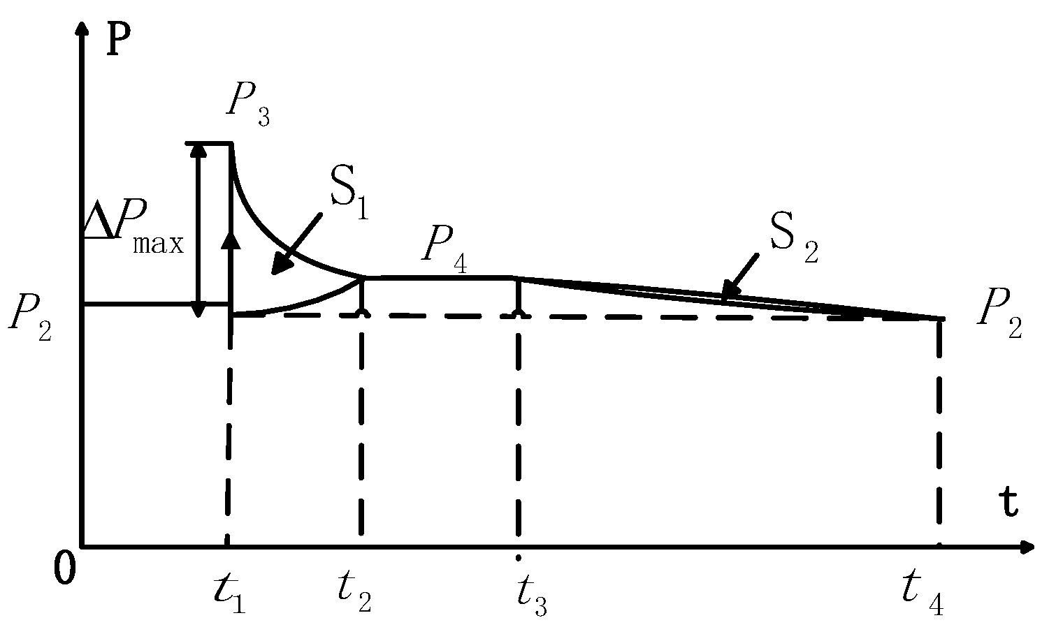
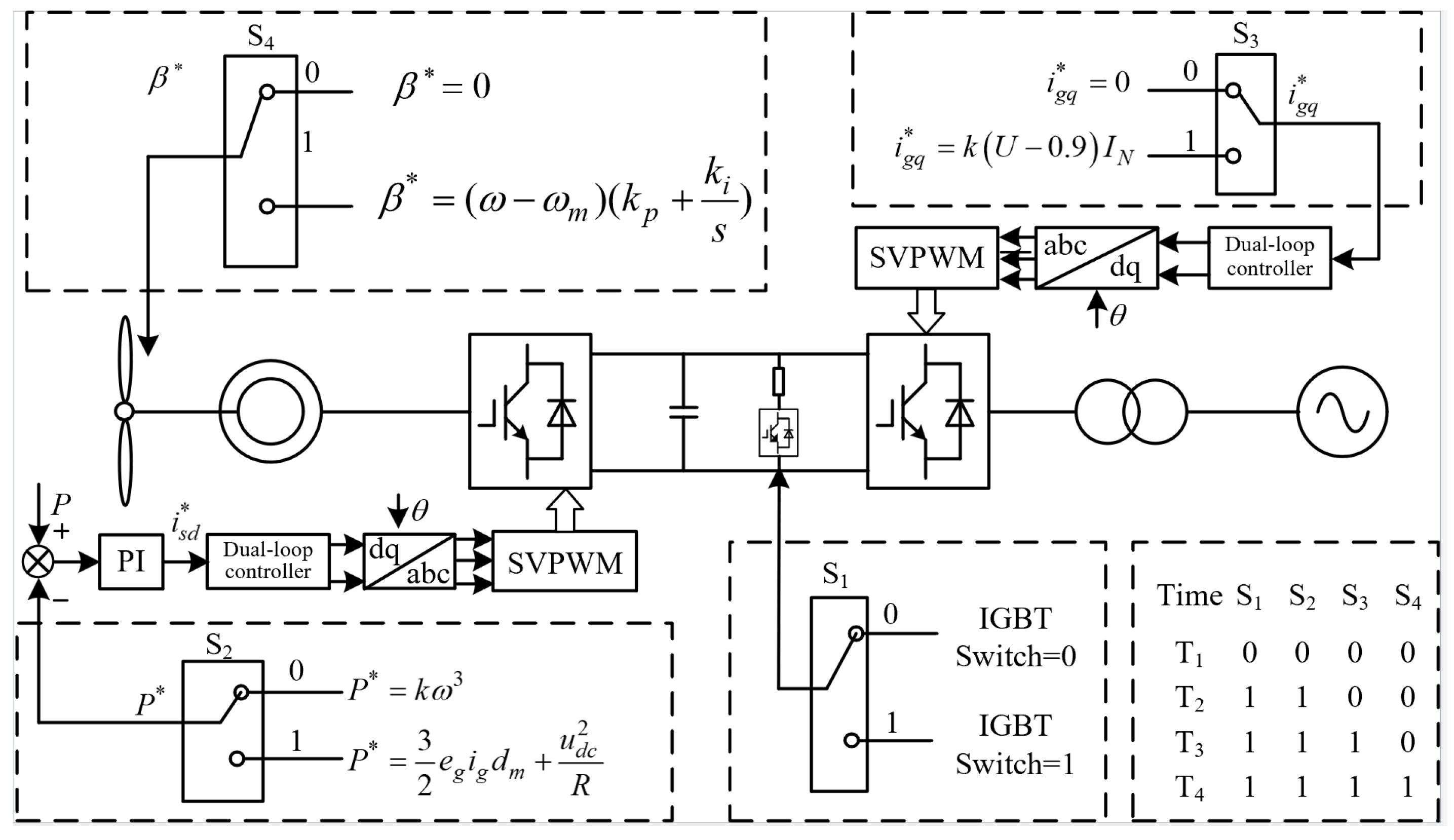
The enhanced LVRT technique for PMSG presented in this work is based on the coordinated regulation of reactive power and rotor energy storage. The proposed technique proposes an integrated strategy that utilizes the dynamic benefits of a crowbar circuit, rotor energy storage, pitch angle adjustments, and management of reactive current in each LVRT step. During LVRT, the total control diagram, depicted in Figure 4, was separated into four stages.
T1: Launch Switch S1: The crowbar circuit is not active since the PMSG is operating in MPPT mode, which means that the paddle pitch angle reference is β*.
T2: Launch Switch S2: The voltage is between 90% and 100%, the crowbar circuit is activated, and the active power reference P* is set with the RKES controller. This results in a portion of the wind energy being captured being converted into kinetic energy of the rotor, lowering the unbalanced power ΔP, and activating the rotor energy storage.
T3: Launch Switch S3: When the voltage falls below 90%, the grid-side converters attempt to maintain the voltage by supplying reactive current igq with a 1.2 p.u. limitation.
T4: Launch Switch S4: Before turning on switch S4, the RKES can be used to make sure that the speed does not exceed the rated speed in order to purchase time for the pitch control’s start-up adjustment. This is because the pitch control requires a specific amount of start-up adjustment time. As a result, the T4 stage can be configured to activate the pitch control once the speed has steadily increased to 95% of the rated speed.
The coordinated control block diagram for the converter is shown in the accompanying Figure 5. In order to establish whether the wind turbine is running in MPPT or LVRT mode, the controller detects the voltage drop of the grid and outputs the matching active power reference value and reactive current reference value .
The dynamic performance of self-synchronous PMSG under LVRT decreases the imbalance of power acting on the crowbar circuit and stabilizes the DC-link voltage and grid-side current based on the suggested strategies. Additionally, the period of the pitch control’s start-up adjustment can be set up later in order to increase the supporting time under LVRT, which shows that the transient grid-forming effects are fulfilled.
The proposed self-synchronous PMSG’s overall flow chart, taking into account the aforementioned technique, is shown in Figure 6. The complete implementation of the controller shown in Figure 6 can be summed up as follows:
Step 1: Initial DC voltage synchronization controller with PMSG stars.
Step 2: Evaluation of the necessity for inertia response and active power frequency to choose when to turn on and off the RKES controller and DC PI control technique.
Step 3: Assessment of whether a voltage source is required during a fault to determine whether to turn the upgraded LVRT controller on or off.
Figure 5.
Coordination control of reactive power and rotor energy storage.

Figure 6.
The overall flowchart of the proposed method.

3. Case Study and Analysis
3.1. Semi-Physical Simulation of Self-Synchronous PMSG
On the basis of the RTLAB platform, a semi-physical simulation model is built in order to validate the pertinent methodologies discussed in this work. Figure 7 displays the platform topology and associated simulation parameters.
Three scenarios built using the RTLAB platform are intended to demonstrate the viability and accuracy of the suggested method. As illustrated in Figure 8, the test circuit is composed of three components: a programmable switch, a self-synchronous PMSG, and a variable load.
3.1.1. Case 1
In the first case, a variable load is used to test the self-synchronous PMSG’s black-start capability and the effectiveness of the kinetic energy storage controller. The findings of RTLAB are displayed as follows:
According to the previously described Figure 9, the PMSG starts and runs based on the MPPT curve (=5°) and the over-speed load-shedding (=0°) curve at the range t = 0–6 s, and the speed climbs to the design operating point. The load increases and the system frequency decreases at time t = 6 s. The PMSG enters self-synchronous control at time t = 9 s and starts to harness the kinetic energy of the rotating system to produce greater power. The speed and power revert to the predetermined operating point when t = 15 s, and the PMSG is then detached from external support. The variable load returns and the frequency increases at t = 12 s. The dynamic reaction mentioned above shows the self-synchronous PMSG’s black start capability.
The performance and the support capacity of PMSG during load-shedding are superior to those of turbine initial-start condition in the time range t = 9–12 s due to the enhanced kinetic energy reserve. The efficiency and ability to provide inertial assistance of the kinetic energy storage controller are shown by the aforementioned. Additionally, the KERS controller can shorten the MPPT adjustment period, as seen in the time range 12–20 s in Figure 9, helping PMSG get to the designated power point. This characteristic indicates a reserve pitch angle area that can be used to generate electricity to offset the need for heavy load-shedding.
The comparison of the traditional VSG controller and PQ controller is shown in Figure 10, the main control strategy of the traditional VSG is from reference [5]. According to the above results, the suggested technique offers a quicker frequency response after system load fluctuations. This is due to the fact that grid-side converters, as opposed to generator-side converters, imitate the operational characteristics of the synchronous machine to accomplish the frequency response of the voltage-sourced grid-configured wind turbine on their own.
3.1.2. Case 2
The second scenario involves testing the PMSG’s phase angle and voltage’s capacity for self-formation. As a result, the switch S1 that is connected to the grid is programmed to open at 7 s and 10 s after the power balance between PMSG output and load has been established. The results are shown in Figure 1. In Figure 11a, the overall performance is given, while Figure 11b records the wave of PMSG after opening the switch connecting with the grid.
The voltage source successfully constructs the AC network under active power balance conditions, and the system frequency and voltage are effectively supported throughout the process in Figure 11. The control quantity of the system and PMSG are stable both before and after the transition. The results presented above demonstrate that the voltage source is capable of producing phase angle and frequency on its own.
3.1.3. Case 3
Case 3 verifies the fault through the ability of self-synchronous PMSG; the transient performance is shown in Figure 12 and Figure 13.
The scenario is a series of cascading events that testify to both the LVRT and HVRT ability. The simulation setting and results are also shown in Table 1.
3.2. Demonstration Wind Farm Project of Self-Synchronous PMSG
To support the suggested approach, a demonstration wind farm project in actuality is provided. The renewable station that consists of 31 PMSGs is located in the middle of Hubei province, China. The capacity of permanent magnet direct-drive wind is 62 MW, as shown in Figure 14. The technical transformation agrees with the semi-physical simulation model from earlier. To finish testing the self-synchronous PMSG’s performance, two scenarios were created.
The ability to regulate power is the first scenario. The wind turbine was able to output active power correctly in accordance with the issued order, with a step response time of approximately 7.5 s for 400 kW and 3.7 s for 200 kW, according to the test findings shown in Figure 15a. Throughout the period, a maximum power variation peak-to-peak value of around 0.045 pu was measured. In Figure 15b, the testers transmit reactive power orders of 10 kVar, 100 kVar, and −100 kVar, respectively, to test the capacity to regulate reactive power. According to the test results, the reactive power response time is about 1.3 s (100 kVar step).
The second case is to verify the inertia ability of self-synchronous PMSG. Through the frequency difference step test to obtain a frequency regulation hysteresis time, rise time, and regulation time of voltage source wind turbine inertia response characteristics, the result curves are shown in Figure 16 and Table 2.
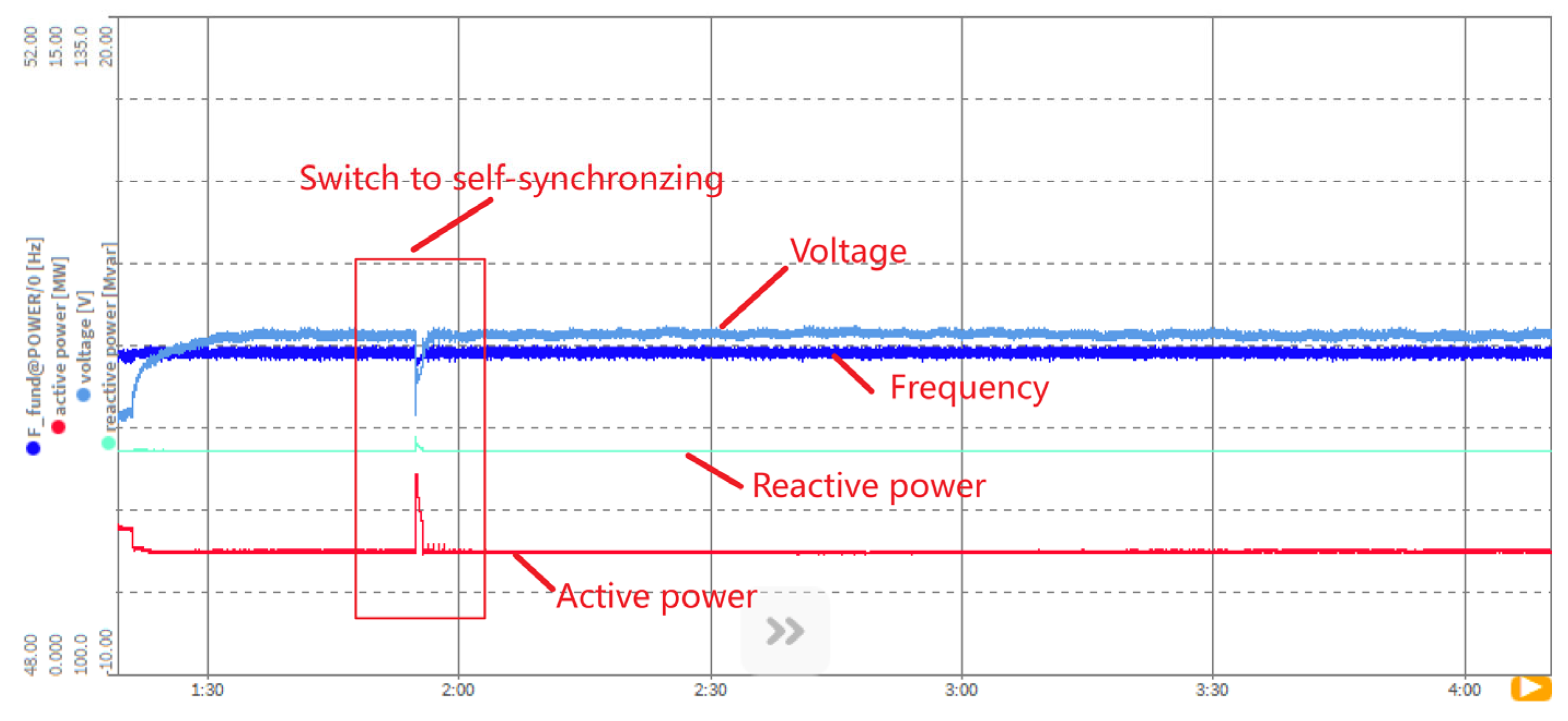
The results of the aforementioned experiments show that the PMSG has inertia response characteristics. The observed inertia reaction time ranges from 150 to 250 milliseconds, and the unit’s corresponding inertia time constant is 8 s. The results presented above clearly show how effective the strategy employed in this study is. Moreover, this paper also gives a testing result of the self-synchronous ability of PMSG. This study also provides a test result for PMSG’s self-synchronous capability. In Figure 17, the PMSG switches to self-synchronization after disconnecting from the grid during power balancing with a controller variable load. The PMSG output’s transient processes for voltage, frequency, reactive power, and active power demonstrate how well the DC voltage synchronization controller works. Grid formation for establishing the frequency and voltage of nearly 100% renewable electricity is demonstrated in practice.
4. Conclusions
This paper introduces a novel grid-forming approach that can be utilized to build an electricity system that uses almost all renewable energy sources to accomplish self-synchronous PMSG. Under dynamic system operation and atmospheric conditions, the recommended control approach provides a defined amount of rotational inertia and transient support without energy conservation or loss. The following are the main conclusions, which are based on an actual wind farm demonstration project and a partially physical platform:
(1) This paper develops the grid-forming CV approach for self-synchronous PMSG. The modeling and engineering application findings demonstrate that the recommended controllers can achieve self-synchronous and grid-forming properties while generating a specific amount of rotational inertia without energy conservation or loss.
(2) This paper offers an RKES controller coupled with the self-synchronous grid-forming CV mentioned above. According to simulation and experimentation, this research takes advantage of the PMSG properties of the rotor to address the conflict between FR and MPPT control during fast wind velocity variations.
(3) This paper proposes an improved LVRT controller that takes the RKES controller into account. This study introduces a four-stage coordinated controller to realize the CV interface during LVRT while taking into account current constraints. The results demonstrate how well the wind turbine can handle fault ride-through while maintaining frequency and voltage during the transient stage.
Admittedly, concerning the proposed planning model, a few aspects can be enriched, such as the multi-machine coordination control, and the primary frequency regulation of wind farms considering the effect of time delay.
Author Contributions
P.H. selected and studied the sources, designed the structure of the manuscript, and wrote the first draft of the manuscript. K.J. and X.J. contributed with supervision over the study of the literature and the writing of the manuscript. K.C. and D.L. modify the topology of this paper. W.W. designs the HIL test platform. Y.C. and B.W. modified the article format. All authors contributed to the manuscript revision, read, and approved the submitted version. All authors have read and agreed to the published version of the manuscript.
Funding
This research received funding from the Science and Technology project of the State Grid Corporation of China, project number: 52153223001Q.
Data Availability Statement
Not applicable.
Conflicts of Interest
Author Pan Hu is employed by State Grid Hubei Electric Power Co., Ltd. The remaining authors declare that the research was conducted in the absence of any commercial or financial relationships that could be construed as a potential conflict of interest.
References
- Wu, C.; Zhang, X.-P.; Sterling, M.J.H. Global Electricity Interconnection with 100% Renewable Energy Generation. IEEE Access 2021, 9, 113169–113186. [Google Scholar] [CrossRef]
- Blakers, A.; Stocks, M.; Lu, B.; Cheng, C.; Stocks, R. Pathway to 100% Renewable Electricity. IEEE J. Photovolt. 2019, 9, 1828–1833. [Google Scholar] [CrossRef]
- Hu, P.; Jiang, K.; Ji, X.; Tan, D.; Liu, D.; Cao, K.; Wang, W. A Novel Grid-Forming Strategy for Voltage-Source Controlled PV under Nearly 100% Renewable Electricity. Front. Energy Res. 2022, 10, 915763. [Google Scholar] [CrossRef]
- Li, M.; Zhang, X.; Zhao, W. A novel stability improvement strategy for a multi-inverter system in a weak grid utilizing dual-mode control. Energies 2018, 11, 2144. [Google Scholar] [CrossRef]
- Fu, X.; Sun, J.; Huang, M.; Tian, Z.; Yan, H.; Iu, H.H.-C.; Hu, P.; Zha, X. Large-Signal Stability of Grid-Forming and Grid-Following Controls in Voltage Source Converter: A Comparative Study. IEEE Trans. Power Electron. 2021, 36, 7832–7840. [Google Scholar] [CrossRef]
- Zhong, Q.-C.; Weiss, G. Synchronverters: Inverters that mimic synchronous generators. IEEE Trans. Ind. Electron. 2011, 58, 1259–1267. [Google Scholar] [CrossRef]
- Liu, J.; Golpîra, H.; Bevrani, H.; Ise, T. Grid Integration Evaluation of Virtual Synchronous Generators Using a Dis-turbance-Oriented Unified Modeling Approach. IEEE Trans. Power Syst. 2021, 36, 4660–4671. [Google Scholar] [CrossRef]
- Cheng, X.; Sun, X.; Chai, J.; Zhao, Y. Virtual synchronous control strategy for doubly-fed induction generator under asymmetrical grid faults. In Proceedings of the 20th International Conference on Electrical Machines and Systems (ICEMS), Sydney, NSW, Australia, 11–14 August 2017; pp. 1–6. [Google Scholar] [CrossRef]
- Shang, L.; Hu, J.B.; Yuan, X.M.; Chi, Y.; Tang, H. Modeling and improved control of virtual synchronous generators under symmet-rical faults of grid. Proc. CSEE 2017, 37, 403–411. [Google Scholar]
- Ebrahimi, M.; Khajehoddin, S.A.; Karimi-Ghartemani, M. An Improved Damping Method for Virtual Synchronous Machines. IEEE Trans. Sustain. Energy 2019, 10, 1491–1500. [Google Scholar] [CrossRef]
- Imai, H.; Orihara, D.; Iioka, D.; Saitoh, H. A Novel Virtual Synchronous Generator Control of PMSG-Based Wind Generation System to Enhance Transient Stability of Power System. In Proceedings of the 2018 IEEE Electronic Power Grid (eGrid), Charleston, SC, USA, 12–14 November 2018; pp. 1–6. [Google Scholar] [CrossRef]
- Sun, Z.; Zhu, F.; Cao, X. Study on a Frequency Fluctuation Attenuation Method for the Parallel Multi-VSG System. Front. Energy Res. 2021, 9, 693878. [Google Scholar] [CrossRef]
- He, J.; Li, Y.W. Analysis, design, and implementation of virtual impedance for power electronics interfaced distributed generation. IEEE Trans. Ind. Appl. 2011, 47, 2525–2538. [Google Scholar] [CrossRef]
- Wang, S.; Hu, J.; Yuan, X. Virtual Synchronous Control for Grid-Connected DFIG-Based Wind Turbines. IEEE J. Emerg. Sel. Top. Power Electron. 2015, 3, 932–944. [Google Scholar] [CrossRef]
- D’Arco, S.; Suul, J.A. Virtual Synchronous Machines—Classification of Implementations and Analysis of Equivalence to Droop Controllers for Microgrids. In Proceedings of the 2013 IEEE Powertech Grenoble Conference, Grenoble, France, 16–20 June 2013; pp. 1–7. [Google Scholar]
- Qin, Y.; Wang, H.; Shao, H.; Yang, R.; Cai, X.; Cao, Y. Self-synchronization and Frequency Response Control of PMSG-Based Wind Turbine Generator. In Proceedings of the 2021 IEEE 12th Energy Conversion Congress & Exposition—Asia (ECCE-Asia), Singapore, 24–27 May 2021; pp. 1163–1168. [Google Scholar] [CrossRef]
- Chinchilla, M.; Arnaltes, S.; Burgos, J.C. Control of Permanent-Magnet Generators Applied to Variable-Speed Wind-Energy Systems Connected to the Grid. IEEE Trans. Energy Convers. 2006, 21, 130–135. [Google Scholar] [CrossRef]
- Haque, M.E.; Negnevitsky, M.; Muttaqi, K.M. A Novel Control Strategy for a Variable-Speed Wind Turbine with a Permanent-Magnet Synchronous Generator. IEEE Trans. Ind. Appl. 2010, 46, 331–339. [Google Scholar] [CrossRef]
- Fang, J.; Tang, Y.; Li, H.; Li, X. A Battery/Ultracapacitor Hybrid Energy Storage System for Implementing the Power Management of Virtual Synchronous Generators. IEEE Trans. Power Electron. 2018, 33, 2820–2824. [Google Scholar] [CrossRef]
- Debnath, S.; Marthi, P.R.V.; Xia, Q.; Pan, J.; Saeedifard, M.; Vipin, V.N.; Chakraborty, S.; Arifujjaman, M. Renewable Integration in Hybrid AC/DC Systems Using a Multi-Port Autonomous Reconfigurable Solar Power Plant (MARS). IEEE Trans. Power Syst. 2021, 36, 603–612. [Google Scholar] [CrossRef]
- Khazaei, J.; Nguyen, D.H.; Asrari, A. Consensus-Based Demand Response of PMSG Wind Turbines with Distributed Energy Storage Considering Capability Curves. IEEE Trans. Sustain. Energy 2020, 11, 2315–2325. [Google Scholar] [CrossRef]
- Musarrat, M.N.; Islam, M.R.; Muttaqi, K.M.; Sutanto, D. Enhanced Frequency Support From a PMSG-Based Wind Energy Conversion System Integrated with a High Temperature SMES in Standalone Power Supply Systems. IEEE Trans. Appl. Supercond. 2019, 29, 3800206. [Google Scholar] [CrossRef]
- Xu, J.; Qian, Q.; Zhang, B.; Xie, S. Harmonics and stability analysis of single-phase grid-connected inverters in distributed power generation systems considering phase-locked loop impact. IEEE Trans. Sustain. Energy 2019, 10, 1470–1480. [Google Scholar] [CrossRef]
- Liu, H.; Xie, X.; He, J.; Xu, T.; Yu, Z.; Wang, C.; Zhang, C. Subsynchronous interaction between direct-drive PMSG based wind farms and weak AC networks. IEEE Trans. Power Syst. 2017, 32, 4708–4720. [Google Scholar] [CrossRef]
- Huang, L.; Xin, H.; Wang, Z.; Wu, K.; Wang, H.; Hu, J.; Lu, C. A Virtual Synchronous Control for Voltage-Source Converters Utilizing Dynamics of DC-Link Capacitor to Realize Self-Synchronization. IEEE J. Emerg. Sel. Top. Power Electron. 2017, 5, 1565–1577. [Google Scholar] [CrossRef]
- Radwan, A.A.A.; Mohamed, Y.A.-R.I. Grid-Connected Wind-Solar Cogeneration Using Back-to-Back Voltage-Source Converters. IEEE Trans. Sustain. Energy 2020, 11, 315–325. [Google Scholar] [CrossRef]
- Huang, Y.; Yuan, X.; Hu, J.; Zhou, P.; Wang, D. DC-Bus Voltage Control Stability Affected by AC-Bus Voltage Control in VSCs Connected to Weak AC Grids. IEEE J. Emerg. Sel. Top. Power Electron. 2015, 4, 445–458. [Google Scholar] [CrossRef]
- Amenedo, J.L.R.; Gómez, S.A.; Alonso-Martinez, J.; De Armas, M.G. Grid-Forming Converters Control Based on the Reactive Power Synchronization Method for Renewable Power Plants. IEEE Access 2021, 9, 67989–68007. [Google Scholar] [CrossRef]
- Hossain, M.J.; Saha, T.K.; Mithulananthan, N.; Pota, H.R. Control Strategies for Augmenting LVRT Capability of DFIGs in In-terconnected Power Systems. IEEE Trans. Ind. Electron. 2013, 60, 2510–2522. [Google Scholar] [CrossRef]
- Shah, S.; Koralewicz, P.; Gevorgian, V.; Wallen, R.; Jha, K.; Mashtare, D.; Burra, R.K.; Parsa, L. Large-Signal Impedance-Based Modeling and Mitigation of Resonance of Converter-Grid Systems. IEEE Trans. Sustain. Energy 2019, 10, 1439–1449. [Google Scholar] [CrossRef]
Figure 1.
The general schematic of the self-synchronous PMSG.

Figure 2.
Small-signal stability analysis. (a) varies from 0.1 to 100; (b) varies from 0.01 to 0.1.

Figure 3.
Relationship during sudden load rise between output power, captured power, and angular velocity.
Figure 3.
Relationship during sudden load rise between output power, captured power, and angular velocity.

Figure 4.
Schematic diagram of power change during deceleration and acceleration.

Figure 7.
Test platform of CV-PV controller under RTLAB/Simulink.

Figure 8.
The test circuit of self-synchronous PMSG.

Figure 9.
Inertial and frequency response simulation based on the RTLAB platform.

Figure 10.
Frequency response comparison among different control techniques. (a) Grid-side frequency; (b) PMSG-side frequency.
Figure 10.
Frequency response comparison among different control techniques. (a) Grid-side frequency; (b) PMSG-side frequency.

Figure 11.
The results of the testing. (a) The overall performance of PMSG; (b) The wave of PMSG after opening the switch.
Figure 11.
The results of the testing. (a) The overall performance of PMSG; (b) The wave of PMSG after opening the switch.

Figure 12.
Low voltage 0.5 p.u. to high voltage 1.25 p.u.

Figure 13.
Low voltage 0.75 p.u. to high voltage 1.25 p.u.

Figure 14.
Structure of wind farm generation system.

Figure 15.
Step response of self-synchronous PMSG power. (a) Active power recordings; (b) Reactive power recordings.
Figure 15.
Step response of self-synchronous PMSG power. (a) Active power recordings; (b) Reactive power recordings.

Figure 16.
Inertia response of self-synchronous PMSG. (a) 50.0→51.0→50.0 at rate ±0.2 Hz; (b) 50.0→49.0→50.0 at rate ±0.2 Hz; (c) 50.0→51.0→50.0 at rate ±0.5 Hz; (d) 50.0→49.0→50.0 at rate ±0.5 Hz; (e) 50.0→51.5→50.0→48 at rate ±0.5 Hz.
Figure 16.
Inertia response of self-synchronous PMSG. (a) 50.0→51.0→50.0 at rate ±0.2 Hz; (b) 50.0→49.0→50.0 at rate ±0.2 Hz; (c) 50.0→51.0→50.0 at rate ±0.5 Hz; (d) 50.0→49.0→50.0 at rate ±0.5 Hz; (e) 50.0→51.5→50.0→48 at rate ±0.5 Hz.

Figure 17.
Self-synchronizing response of the PMSG with a controller variable load.


Table 1.
The simulation setting and results.
| Active Power 0.8 p.u., Reactive Power 0.1 p.u. | |||
|---|---|---|---|
| Scenario | Voltage/p.u. | Fault Duration/ms | Steady-State Average Value of Reactive Current (p.u.) |
| Low and high voltage faults through condition | 0.75–1.2 | 0.75 p.u./1705 1.2 p.u./10,000 | 0.551, −0.736 −0.772, 0.569 |
| 0.5–1.25 | 0.5 p.u./1214 1.25 p.u./1000 | 0.832, −0.963 −0.966, 0.825 | |
Table 2.
Inertia response characteristics.
| Frequency Change Rate Setting (Hz/s) | Frequency Change Process (Hz) | Measured Value of Active Power Regulation (pu) | Response Time(s) | Results |
|---|---|---|---|---|
| ±0.2 | 50.0→51.0→50.0 | 0.035 | 0.204 | Figure 16a |
| 50.0→49.0→50.0 | 0.036 | 0.165 | Figure 16b | |
| ±0.5 | 50.0→51.0→50.0 | 0.083 | 0.154 | Figure 16c |
| 50.0→49.0→50.0 | 0.087 | 0.170 | Figure 16d | |
| 50.0→51.5→50.0→48 | 0.088 | 0.247 | Figure 16e |
Disclaimer/Publisher’s Note: The statements, opinions and data contained in all publications are solely those of the individual author(s) and contributor(s) and not of MDPI and/or the editor(s). MDPI and/or the editor(s) disclaim responsibility for any injury to people or property resulting from any ideas, methods, instructions or products referred to in the content. |
© 2023 by the authors. Licensee MDPI, Basel, Switzerland. This article is an open access article distributed under the terms and conditions of the Creative Commons Attribution (CC BY) license (https://creativecommons.org/licenses/by/4.0/).
Share and Cite
MDPI and ACS Style
Hu, P.; Jiang, K.; Ji, X.; Cai, Y.; Wang, B.; Liu, D.; Cao, K.; Wang, W. A Novel Grid-Forming Strategy for Self-Synchronous PMSG under Nearly 100% Renewable Electricity. Energies 2023, 16, 6648. https://doi.org/10.3390/en16186648
AMA Style
Hu P, Jiang K, Ji X, Cai Y, Wang B, Liu D, Cao K, Wang W. A Novel Grid-Forming Strategy for Self-Synchronous PMSG under Nearly 100% Renewable Electricity. Energies. 2023; 16(18):6648. https://doi.org/10.3390/en16186648
Chicago/Turabian StyleHu, Pan, Kezhen Jiang, Xiaotong Ji, Yuze Cai, Bo Wang, Dan Liu, Kan Cao, and Wei Wang. 2023. "A Novel Grid-Forming Strategy for Self-Synchronous PMSG under Nearly 100% Renewable Electricity" Energies 16, no. 18: 6648. https://doi.org/10.3390/en16186648
Note that from the first issue of 2016, this journal uses article numbers instead of page numbers. See further details here.