
Energy Management of Hybrid DC Microgrid with Different Levels of DC Bus Voltage for Various Load Types
by
 , , and
Mahmoud F. Elmorshedy
1,2,* ,
,
Umashankar Subramaniam
1,*,
Jagabar Sathik Mohamed Ali
1,3 and
Dhafer Almakhles
1 1
Renewable Energy Lab., College of Engineering, Prince Sultan University, Riyadh 11586, Saudi Arabia
2
Electrical Power and Machines Engineering Department, Faculty of Engineering, Tanta University, Tanta 31733, Egypt
3
Department of Electrical and Electronics Engineering, SRM Institute of Science and Technology, Kattankulathur Campus, Chennai 603203, India
*
Authors to whom correspondence should be addressed.
Energies 2023, 16(14), 5438; https://doi.org/10.3390/en16145438
Submission received: 16 February 2023
/
Revised: 9 June 2023
/
Accepted: 4 July 2023
/
Published: 17 July 2023
(This article belongs to the Special Issue Sustainable Energy Transition, Utilization and Management to Achieve SDG 7)
Abstract
:This article suggests a hybrid DC microgrid (HDCMG) with different levels of DC bus voltages to use for various types of loads. The available sources in the HDCMG are wind generating systems (WGSs), photovoltaic (PV) systems, battery banks, and the AC grid for emergencies. The various levels of the DC bus voltages are 760 V, 380 V, and 48 V for different application uses such as electric vehicles and home applications. In addition, the controller plays an important role in the proposed system to achieve the desired DC bus voltage levels and extract the maximum power point (MPP) from the WGS and PV systems. In order to check the power continuity for the critical loads and improve the overall system performance, a suggested energy management strategy (SEMS) is developed. The SEMS is based on the optimum generated power and the state-of-charge (SOC) of the battery banks. Further, the SEMS is developed as a way to prevent battery storage from overcharging and deep discharging. The mathematical relations of the proposed HDCMG and MPP tracking are described. The bidirectional 3-Φ inverter connects the 760 V bus voltage to the AC grid for regulating this DC bus by absorbing the excess power or supplying the required power during the shortage in the generation and the low SOC of the battery storage. Buck converters with controlled duty cycles rather than constant duty cycles are used to obtain 380 V and 48 V from 760 V to achieve better dynamic responses. The overall HDCMG is evaluated using the MATLAB/Simulink package under different working cases to verify the capability of the control system and the PEMS. The obtained results are discussed and show the good performance and the capability of the overall system under the different scenarios, including (i) a comparison between variable duty and constant duty; (ii) high/low generated power and the SOC of the battery in the acceptable region; (iii) high/low generated power and the SOC of the battery in the critical region; and (iv) high/low generated power and the SOC of the battery in the overcharging region.
1. Introduction
Greenhouse gas emissions need to be lowered to save the planet from further damage caused by rising temperatures caused by global warming. Renewable energy sources (RESs) are mature power generators that do not emit carbon dioxide compared to fossil fuels. The incorporation of RESs is resulting in structural adjustments being made to the existing structure of the electric distribution grid. In the past few decades, more academicians and industries in the power electronics industry have become interested in DC and AC microgrids as part of an effort to develop technological innovations and solve technical problems such as frequency and power balance through the integration of renewable energy sources and distribution grids [1,2]. These strategies lower the CO2 emissions while protecting the energy supply’s security and meeting consumer demand [3,4,5,6].
In addition, microgrids play an important part in the formation of future intelligent power systems because they make it easier to combine distributed energy resources, loads, and energy storage devices [7,8,9,10]. DC microgrids have several benefits that make them more appealing than AC microgrids, including a reduction in the conversion stage and an absence of distortions caused by harmonics and voltage synchronization, reducing the cost of the system, making it more efficient and reliable, and not having any issues regarding the reactive power and frequency control and synchronization. However, many existing systems require an AC supply and the transmission of AC voltage is well-established compared to DC voltage transmission [11].
Therefore, power management strategies are considered one of the most important parts of DC microgrids and this is discussed in different articles [12,13,14,15,16,17,18]. The two-level energy management strategy is implemented in [12] to balance the operational stability of the PV–fuel cell–battery-based DC microgrid. This is accomplished by dividing the control levels of the devices and the system. In order to equitably distribute the system’s net power between the battery and the fuel cell, the proposed method uses a strategy that minimizes the amount of equivalent consumption. In [13], the presentation of a new energy management control technique is outlined that is based on the fuzzy logic controller and high-order sliding mode. This technique is intended for use with smart DC microgrids. The energy sources used by the microgrid are the battery bank, wind, PV, and tidal. It is proposed to implement a source-side intelligent control in order to improve power quality and extract the maximum amount of energy from hybrid sources. The controller that has been suggested ensures that there will be no disruptions in service.
By employing the global optimization solver BARON [14], a new energy management method is proposed, which takes into account the distribution grid’s no-load, nonlinear losses, and the costs associated with starting up and shutting down the DG. The optimization method that has been suggested ensures accuracy and robustness during multi-objective operation scenarios, as well as those involving minimum price and minimum emission. Meanwhile, [15] discusses autonomous microgrid power management strategies for distributed generation (DG) units in multiple-DG systems. These strategies deal with real and reactive power, respectively. In order to investigate the impact of power management on the dynamics of a microgrid, especially after islanding incidents, we need to evaluate DG unit–network interactions, study the eigenstructure of a three-DG microgrid, determine whether or not the microgrid is stable, design and optimize control parameters, and design and implement microgrid control. In [16], the power management system (PMS) for DC microgrids is suggested as being straight forward and ideal. A power switching circuit is used by the system to connect the energy storage system (ESS), DC load, and each nanogrid (NG) of the DCMG. Ref. [17] describes a system with bidirectional AC/DC converters (BADCs) and bidirectional DC/DC converters (BDDCs) that connect several subgrids to a single bus. In order to have the interacting subgrids run in cooperation and assist one another, this study suggests a decentralized power management strategy for the hybrid microgrid. Ref. [19] suggests combining a hybrid alternative energy system with a standalone AC microgrid. The overall strategy of power management works to optimize the flow of power, and the FC works to compensate for any power shortages that may occur. The reduction in daily operating costs is the primary objective of this research [20]. This will be accomplished by applying predictive model control to errors in power generation and load prediction. The optimization technique makes day-ahead energy management much more efficient. By continuously bringing the control values up to date, the intraday rolling horizon energy optimal management strategy can correct any forecasting errors that may have occurred. This study uses model predictive control to cut down on daily operating costs by reducing the error that occurs between the prediction of load and the generation of power. Energy management is optimized for the day ahead by using intraday rolling horizon energy management and optimizing control values to compensate for errors in forecasting [21]. Multiple battery energy management systems for a microgrid are presented in [22] that rely primarily on photovoltaic and diesel generators as they are primary sources of electricity. The strategy that is being proposed is to lessen the amount of time that the DGs are actively working, concurrently manage multiple batteries with distinct properties, and cut down on power fluctuations caused by photovoltaic cells. Additionally, the operating hours of the DGs would be cut down, and the battery’s lifespan would be extended by controlling the battery charge and discharge rate. The results of this study, which focuses on the potential impact of demand response on a microgrid’s total system emissions and economics, are demonstrated in [23].
Further, ref. [24] outlines the presentation of an advanced control scheme for multiagent systems that are based on a hierarchical management and control structure. The hybrid energy generation system is made reliable, stable, and efficient in terms of cost thanks to a hierarchical management and control scheme that is based on multiagent systems. A new energy management strategy is proposed [25] for medium-voltage DC systems. This strategy makes use of two-time-scale coordinates in order to deal with the effects of uncertainty as well as the widespread utilization of renewable energy sources. Through the simultaneous co-optimization of operating points and droop coefficients, both productivity and safety can be brought to their highest possible levels. Coordination, operation, and cost distribution of the proposed energy management system among members of the coalition are all handled through the medium of a cooperative game. Every microgrid composed of multiple agents is an effective energy saver. When compared to alternative strategies, the optimal policy results in an 87.86% reduction in operating costs for the MG [26].
All of the research articles just discussed were primarily centered on designing and controlling novel architectures for use in a single microgrid, with or without the use of fossil fuel as a source. The majority of microgrid solutions, on the other hand, are designed for hybrid (DC/AC) systems. The multiagent/level energy management is also discussed in various research papers [27,28,29,30,31,32,33]. Also, the objective of the multiagent system is to connect and coordinate all of the microgrids through a variety of new control algorithms and energy management strategies. Nevertheless, the majority of research is focused on managing demand response, time control, cost reduction, and other related topics. Only a handful of studies have looked at the power quality of DC microgrids [34,35]. In addition, many researchers have suggested an energy management for different systems such as [29,30,31,32,33,34]. In [36], authors proposed a standalone microgrid (PV/Battery hybrid) with a power management strategy. The PV/Battery system acts as a voltage source using an adaptive droop management method to meet load demands while controlling battery charging and discharging activities. However, the droop control methods have been used in the microgrids which consist of PV/Battery systems, and they have a lot of disadvantages including poor transient performance and poor power sharing accuracy [37]. Further, in [38], the system is small and only contains the PV and the battery to supply the DC load where there is no priority to the load and only a low level of DC bus voltage is used. Also, in [39], a networked controller with a virtual impedance droop architecture for energy management and load sharing is presented. This strategy, however, calls for communication channels between the ESS devices. A DC microgrid energy management and SoC balancing method is described in [40]; however, it is not appropriate for hybrid ESS because the droop parameters are taken into account as a time constant which could lead to ineffective power sharing. Meanwhile, in [41], an energy management system is proposed for a DC microgrid based on the voltage compensation and the battery SoC management algorithm.
In this investigation, the suggested system must be able to fast charge the electric vehicles, meet the power demand of home appliances both critical and noncritical, and use the low-voltage LED, as well as inject/consume electricity into/from the mains. Moreover, a user-friendly algorithm for managing demand response based on the priority of critical loads is being developed. Briefly, this article brings a new look to the existing literature in the following areas: (I) renewable energy sources, (II) hybrid DC microgrid systems, (III) applied control algorithms for DC link voltage and MPPT, and (IV) power management strategies. Therefore, the following are the study’s main contributions:
- A comprehensive model is established to generate the power from the PV system and the wind generating system as well as the characteristics of the MPPT.
- An adaptable architectural design to meet the electricity requirement.
- Three voltage buses primarily use the major bus (760 V) for fast-charging EVs, the secondary bus (380 V) to distribute power to each home appliance, and the third bus (48 V) for low-voltage appliances and LEDs.
- Instead of static switches, this development transfers power across buses using bidirectional power converters, making it feasible to set the buses’ voltages.
- Three levels of control algorithms are designed: (i) bidirectional inverter control for grid synchronization; (ii) a DC-DC algorithm for photovoltaic systems; and (iii) an AC-DC algorithm for wind energy generation.
- The first level of control consists of the following components: (i) a DC-AC three-phase inverter with grid synchronization; (ii) a maximum power point tracking (MPPT) algorithm for the PV system that makes use of IC; and (iii) a diode front end (DFE) for the WGS generating system that uses the maximum power point algorithm using the PI controller.
- A coordinated control technique is carried out to regulate the current and power as part of the second level of control.
- The third level of control utilizes an EMS method equipped with a user-friendly algorithm to determine the suitable set points for all power sources following their respective operational targets. In addition to being efficient in supplying the electrical power for both critical and noncritical DC loads where complex algorithms are avoided, it has a simple implementation in the hardware and it does not require high processing, as it is based on ON/OFF switching, assisting the control in regulating the DC bus voltage at the required levels, and improving the stability of the proposed system by injecting the excess power into the grid or absorbing the shortage power from the main grid.
The article is organized as follows. Section 2 discusses the proposed DC microgrid system mathematical modeling. Section 3 presents the detailed description of the proposed control techniques for the suggested HDCMG. Section 4 describes the suggested energy management strategy. Section 4 evaluates the proposed HDCMG along with their interpretation. Meanwhile, Section 5 makes a comparison between the proposed system and the literature on the DC microgrid systems. Section 6 presents the final conclusions of the research, indicating its limitations, and future directions of research in this field.
2. The Proposed DC Microgrid System Mathematical Modeling
As shown in Figure 1, the proposed hybrid renewable energy system consists of four major components: PV system, WGS, battery storage (BS) system, and grid. The generated power supplies both critical and noncritical loads. The ratings of all system components are listed in Table 1. Each part of the hybrid microgrid energy (HME) system has a control unit that executes particular operations under distinct circumstances. The subsections are organized after the technical specifications and each component’s mathematical representations.
2.1. Mathematical Representation of the WGS
Within the WGS, the wind turbine (WT) is coupled to the permanent magnet synchronous generator (PMSG). A DFE is used to manage the generator’s output power, or MPPT, and comprises an unregulated rectifier followed by a boost converter to convert alternating current (AC) to direct current (DC). In [42], Table A1 in the Appendix A lists the technical specifications of the WT under study. It depends on several factors, expressed in (1), including what percentage of the generated power comes from the WT. The WT power output can be calculated in real time as a function of the wind speed turbine coefficients and using (2) [43].
In the meantime, the WT’s wind power coefficient is represented by the following formulations [44,45]:
where
| Ca = 0.51760 | Cb = 116.0 | Cc = 5.0 |
| Cd = 0.40 | Cf = 21.0 | Cg = 0.00680 |
Meanwhile, the mathematical model of the PMSG is expressed by the following relations.
2.2. The Mathematical Model of the PV System
One of the main sources for the planned HDCMG system is a PV array. The monocrystalline silicon flat plate SunPower-305-SPR PV model used in the proposed study has an a peak efficiency of 18.7% and an average power rating of 305 watts [46]. Based on manufacturing data [46], Table A2 in the Appendix A depicts the technical details of the PV module used. In order to display the PV output power and the actual PV cell temperature, the following relation is used [47,48].
2.3. The Mathematical Model of the PV System
The energy in the battery storage (BS) is restricted by the SOC boundaries as expressed in the following relations [49].
2.4. Mathematical Representation of the LED
Although there are many other kinds of lighting sources, light-emitting diodes (LEDs) are anticipated to take up a significant percentage of the lighting market for the foreseeable future due to their high luminous efficiency [50]. There are many advantages of using LEDs such as long lifetime, low power consumption, small size, easy dimming, environmentally friendly, and so on [51,52]. The packaging and thermal management of the LED module, which is made up of numerous low-power LED units, limit the rating power of each individual LED unit. The cost of LEDs has significantly decreased due to advancements in LED manufacturing technology, and as a result, they are widely employed in many diverse applications, including display backlighting, residential illumination, traffic lighting, and urban landscape lighting [53,54]. The different mathematical model and simulation of the street lamp is discussed in detail in [55], where the rated voltage and power are 18 V and 25 W. Among the five methods, the six-term Gaussian fitting method has the best fitting performance and it is expressed by
where
| a1 = −88.72 | b1 = 19.98 | c1 = 1.929 |
| a2 = −0.05488 | b2 = 15.49 | c2 = 0.8177 |
| a3 = 0 | b3 = 0.2712 | c3 = 2.239 |
| a4 = 98.00 | b4 = 20.12 | c4 = 2.017 |
| a5 = −0.02065 | b5 = 17.28 | c5 = 0.3815 |
| a6 = −0.01613 | b6 = 16.80 | c6 = 0.4395 |
2.5. Mathematical Representation of the AC Grid
The linking converter is typically used to transfer power between MG systems that are AC and DC. A general model of the prime power converter (PPC) was created. The converter rating should, in accordance with [56], be more than the combined produced power, as given by
Meanwhile, the terminal voltage of the PPC in the dq-axis coordinates is given by
3. Proposed Control Techniques for the Suggested HDCMG
The detailed analysis of the whole control methods used in the systems and converters will be discussed in the following subsection.
3.1. Extracting the Maximum Power from the PV System
High temperatures cause a reduction in PV power and efficiency, despite an increase in these two parameters due to high PV radiation levels. Even when the temperature and radiation change, the peak power point (Vmpp) solar output voltage must be kept constant. Numerous papers have looked into how MPPT approaches might be used to achieve this. The MPPT approaches can be classified into two primary classes: direct approaches, such as perturbation and observation (P&O), incremental conductance (IC), and sophisticated techniques like fuzzy logic-based schemes and ANN, and indirect approaches, such as the open-circuit and short-circuit methods [57]. It is challenging to correctly monitor the MPP using indirect approaches at any cell temperature or solar energy level because it necessitates prior knowledge of the PV system’s operational characteristics. On the other hand, in the direct approaches, the signal that serves as a reference for a DC-DC converter is modified in order to manage the voltage levels of both PV and the DC bus. The key benefits of using P&O or IC technologies are their lower cost, their interoperability with industrial inverters and digital controllers, and the fact that no prior understanding of the PV system is required [58]. The voltage oscillation caused by brief changes in the weather is the P&O method’s principal drawback. The IC technique, however, enhances tracking speed and accuracy issues [59]. However, despite their complexity and high application costs, applying intelligent approaches has increased tracking speed and precision over direct ones. To improve the system characteristics, the IC approach is used in conjunction with a direct control method [60]. The PV array’s MPPT control is in current control mode and is shown schematically in Figure 2, showing the diagram where the reference current is generated based on the IC flowchart shown in Figure 3. The PI control is utilized to boost calculation precision and lower ripple oscillation and hence the tracking accuracy can be improved.
3.2. Extracting the Maximum Power from the WGS
Due to their capacity for achieving maximum power and a wide range of speeds, DFIG and PMSG have been frequently utilized in WGSs [61]. There are three types of wind generating systems: full-controlled variable speed, variable speed with pitch control, and WT fixed speed [62]. Power signal feedback (PSF), wind speed measurement (WSM), and P&O are the three categories into which the MPPT techniques for variable speed WTs are categorized in the literature. For the MPP to be tracked using the shaft speed control, the maximum power curve must be communicated to the controller using the PSF approach. The P&O approach does not require prior knowledge of the maximum WT power at various wind speeds or generator data [63]. Although the P&O approach is highly reliable, it is inefficient. The wind and turbine speeds are employed as the two feedback signals in the WSM technique to determine the tip speed ratio (TSR). Consequently, this method is often referred to as the TSR [64]. The variable speed turbine (VST) uses pitch angle control (PAC) to maintain the WT’s rated output power and minimize overloading [62]. As the DFE is adopted in this study, two cascaded PI controllers are used to protect the generator against overcurrent and generate the duty cycle for the DC-DC boost converter and hence extract the maximum power from the wind speed. The optimal power is extracted when the wind power coefficient is 0.48 for the used WT parameters [65]. Figure 4 depicts the MPPT technique from the adopted WGS.
3.3. DC Bus Control Based on BES
The primary goal of the BES is to keep the DC bus voltage constant at 760 V under various operating conditions. As shown in Figure 1, this objective is attained by using the battery banks that are controlled by a bidirectional buck-boost converter. The battery voltage level in these converters can be set lower than the intended reference value [66]. The buck-boost converter’s control function entails adjusting, monitoring, and supervising battery functioning during the day and night. Depending on the control action, the BES can be in any mode of three: discharging, charging, or standby. The control is made up of two cascaded PI controllers, as shown in Figure 5, where the first one, the outer voltage control loop, is in charge of creating the reference signal for the intended battery current in order to limit the battery from the maximum discharge. The input for this PI controller is the DC bus voltage error. Meanwhile, the second PI controller, the inner current control loop, is responsible for regulating the BS current and the output signal is the duty cycle which determines the mode of operation. This mode is primarily determined by the DC bus voltage level that corresponds to the necessary 760 V. To create the necessary pulses for the converter switches, this duty cycle is compared to the carrier signal. In the case of higher generated power from the WGS and the PV system, the BS is in the bucking/charging mode when the DC bus voltage is higher than 760 V. On the other hand, if there is lower generated power from the HRES, the BS works in discharging/boosting mode to maintain the DC bus voltage at 760 V.
3.4. DC Bus Control Based on the Main Grid
During emergency situations, low generated power from the HRES, and when there is not enough energy stored in the battery, the critical load should be supplied from the main grid. Further, in the case of high generated power, there being more excess power over the critical and noncritical load, and the BS being fully charged, the main grid has to absorb the extra power to make the system stable. As a result, the grid’s goal is to control the DC bus voltage by absorbing excess power or giving the necessary power to the loads. Based on the mathematical representation of the main grid in (19) and (20), two PI controllers are used to regulate the active and reactive power (i.e., the dq-axis currents) through the adjusting values of the dq-axis voltages (, ), in addition to one PI controller to regulate the DC voltage. Meanwhile, the output of this PI controller serves as the reference d-axis current where the input is the DC bus voltage error. The analysis starts with the balance between the input and output power as expressed by [67]
By adopting the voltage-oriented control, vqg = 0, Equation (22) is updated to
By linearizing (23) around the equilibrium point and neglecting the higher-order and steady-state terms, it becomes as follows
It is observed that the d-axis output current value influences the value of the DC bus voltage. The block diagram of the DC bus voltage control is shown in Figure 6.
4. Suggested Energy Management Strategy
The generated power might either be higher or lower than the load demand due to the variable nature of renewable energy sources of wind and solar power. Therefore, a PEMS is needed to enhance the HDCMG system’s performance and capability under different circumstances and conditions. Based on the proposed HDCMG system, shown in Figure 1, a new EMS is presented as illustrated in Figure 7. The main objectives of this EMS are:
- Managing the total generated power across all generating sources.
- Supplying both critical and noncritical loads with the most power possible from each generating unit using MPPT techniques.
- Assisting in stabilizing the DC bus voltage under different working conditions.
- Giving the priority to the critical loads and the battery storage system.
- Connecting or disconnecting the grid during extreme working cases to ensure the system is safe and stable.
More details about this new EMS are discussed in the flowchart.
5. Comparison between the Proposed System and the Literature on the DC Microgrid Systems
In this section, the proposed system is compared with the numerous studies of the DC microgrid where different levels of DC voltage are adopted in many different applications, where telecommunication applications require 48 V and transport applications like camping cars work with 12–24 V [68]. A 250 W DC solar nanogrid with a 24 V DC distribution bus was designed for residential applications using a 24 V DC bus and was presented in [69]. In some of the literature, a small-scale DG system, such as a single house or structure, is referred to as a nanogrid; nevertheless, the term “microgrid” is used in this article in a broader sense. In the data center literature, a different voltage range of 380–400 V was examined. In [70], a 380 V DC test system that was built in Obihiro, Japan, was demonstrated. It was determined that the system enabled the creation of an autonomous community energy system in addition to reducing the environmental load and increasing energy efficiency. The authors of [71] have constructed a DC microgrid experimental platform with a 380 V bus voltage level. The system consists of a PV array, a WT, a lithium battery pack and a supercapacitor energy storage system, LED lighting, and regulated electric loads. Furthermore, the high voltage level is adopted for fast charging the electric vehicle. Some of the well-known producers of electric vehicles have recently switched to higher-voltage batteries in order to gain the advantages of lower current, greater power density, and quicker charging times [72]. In addition, in Saudi Arabia, the metrology and quality organization (SASO) has adopted Standard IEC 61851-1 as a Saudi standard with modification for EC charging modes. Table 2 shows electric vehicle charging modes based on the Saudi Arabia Standard [73].
Based on the previous discussion and the survey, Table 3 illustrates a brief comparison of the DC microgrids among the different references and the proposed one. Meanwhile, Table 4 shows different DC loads with their voltage level and power rating ranges. Finally, Table 5 makes a comparison between the proposed DC microgrid and the literature in terms of voltage levels and the tested appliances.
6. Evaluation of the Proposed HDCMG
The proposed hybrid DC microgrid with the overall control techniques and the proposed energy management system is evaluated in this section. This evaluation is developed via MATLAB/Simulink. The evaluation includes four main objectives: extracting the maximum power from both the PV and wind systems; regulating the three different DC-link voltage constants at the reference values; ensuring uninterrupted power to the critical loads; and validating the capability of the proposed energy management system. It has to mention that the wind generating system starts to inject power after 2 s, where it starts without load to reach the steady state. Meanwhile, the PV system injects the power from the first instance, where it is a static system. In the following section, the technical evaluations are discussed and analyzed with the help of four different scenarios.
6.1. Comparison between the Use of PI Controller and Constant Value for the Duty Cycle
In this case, the wind speed is constant at 6 m/s while the radiation value changes as illustrated in Figure 8. The value of the 760 V DC-link voltage is regulated either with the help of the cascade PI controllers for the battery storage system or the grid-side converter according to the generated switching state from the proposed EMS. The adopted control technique for extracting the MPP from the WS and the PV system succeeded without any difference when using a constant or regulated duty cycle as shown in Figure 9 and Figure 10, respectively. Meanwhile, the three different levels of the DC-link voltages have different responses, where the profile of the actual value of the 760 V based on the controlled duty reaches the reference value and has a higher overshot during the step response in comparison with the constant duty as illustrated in Figure 11. It can be noticed that this difference is due to the indirect influence of the controlled duty for the other two DC-link voltages. The direct use of the controlled duty on 380 V and 48 V DC-link voltages compared to the constant duty is shown in Figure 12 and Figure 13, where the use of controlled duty is much better than the use of constant duty. The advantage of controlled duty is that it prevents the directly connected load from over- and undervoltage and hence increases the lifetime of the application as illustrated from the critical home and LED power loads indicated in Figure 14 and Figure 15, respectively. On the other hand, the EV load power is smooth due to the use of controlled duty based on the SOC in the two cases, as is clear in Figure 16.
6.2. Constant Wind SPEED and Variable Solar Radiation
The overall system behavior based on the control techniques and the proposed EMS is tested in this case under a constant wind speed of 6 m/s, initial SOC value of 70%, and variable radiation, as illustrated in Figure 17. Figure 18 shows the maximum generated power from the wind speed and the PV under different radiations. The connection or disconnection of the battery storage, grid, critical load is determined by the proposed EM strategy. The priority of the EM is to deliver the required power to the critical loads. The critical load demand powers are offered in Figure 19. Based on the total amount of the generated power, the load demand power of the critical loads, and the value of the SOC of the battery storage illustrated in Figure 20, the switching states from the proposed EM are shown in Figure 21. It can be observed that the switches of the three critical loads and the battery storage are ON while the switches of the grid and the main noncritical loads are OFF, which means that the SOC is less than 90 and the generated power is greater than the load demands. Due to the change in the generated power, the battery status of charging or discharging with a different sharing power is shown in Figure 22. The dynamic response of the three DC bus voltages is depicted in Figure 23, Figure 24 and Figure 25.
6.3. Variable Wind Speed as Well as Solar Irradiance
This scenario is offered to check the proposed HDCMG with the proposed EM strategy under variable solar radiation and wind speed as illustrated in Figure 26 and Figure 27, respectively. The corresponding generated power to this variation and the critical load power are shown in Figure 28 and Figure 29, respectively. The SOC of the battery storage is depicted in Figure 30. The switching states generated from the proposed EM are clarified in Figure 31. It can be seen that when the generated power is less than the load demand and the SOC is less than 20%, the switch of the battery storage is OFF and the switch of the grid is ON to prevent the battery from deep discharging as demonstrated in Figure 32, Figure 33 and Figure 34. Figure 32 shows the active and reactive power supplied to the critical load from the grid where the value of the active power decreases with the increase in the generated power, but the total generated power is still lower than the load power. Meanwhile, when the generated power is greater than the load demand, the switch of the grid is OFF and the battery storage is ON; hence, the grid power becomes zero and the battery starts to charge. The values of the 760 V, 380 V, and 48 V DC-link voltages are displayed in Figure 35, Figure 36 and Figure 37, respectively.
6.4. Effect of the Proposed PEMS
In this case, the overall system with the proposed EM strategy is discussed under a 6 m/s wind speed and 500 W/m2 solar irradiance. The WS is connected after 4 s. The wind power coefficient tracks the reference value as shown in Figure 38 while the maximum generated power from both WS and PV systems is illustrated in Figure 39. For the first 2 s, the generated power supplies the critical loads, and the proposed EM is turned off to make sure that the critical load is supplied with the appropriate power, and it is activated after 2 s. The switching states after activation of the EM strategy are shown in Figure 40, where the noncritical loads switch to having an ON status. The noncritical load power, battery storage, and SOC are shown in Figure 41, Figure 42 and Figure 43, respectively. It can be observed from Figure 43 that when the EM strategy is activated, the noncritical load is switched ON and the battery starts to discharge the power to these loads to prevent the battery from overcharging. This confirmed that the adopted EM increases the lifetime of the battery. Finally, the values of the 760 V, 380 V, and 48 V DC-link voltages are displayed in Figure 44, Figure 45 and Figure 46, respectively.
7. Conclusions
This work suggested a complete hybrid DC microgrid system, where this system contains different levels of DC bus voltages including high, medium, and low values for different real applications. There are two kinds of renewable energy sources that are adopted in the suggested system, which are PV and wind energy conversion systems. The mathematical models of the overall system components are discussed in detail in the presented work. The overall HDCMG system is improved by the adopted control techniques of MPPT for both the WGS and PV systems. Moreover, the adoption of variable duty cycles regulates the DC bus voltages. A detailed analysis of the whole control methods used in the systems and converters is discussed. After that, more enhancements to the HDCMG system are attained by proposing a power management strategy. The generated power from the renewable energy sources aided with the battery storage or main grid and is used to supply critical and noncritical loads based on the suggested PEMS. Moreover, the system with the control and PEMS is simulated and tested under four circumstances representing seasonal effects (i.e., comparison between the use of PI controller and constant value for the duty cycle, constant wind speed and variable solar radiation, variable wind speed as well as solar irradiance, and effect of the proposed PEMS during constant wind speed and solar irradiation). The results confirmed the fast and good dynamic response while using variable duty instead of constant duty. In addition, the capability of the PEMS to keep the system stable by supplying the extra power to the noncritical load or consuming power from the main grid, which increases the lifetime of the battery and prevented overcharging or under-discharging, was discussed in case 5.3 and case 5.4. Finally, this work can be extended and has future work prospects such as:
- Applying sliding mode control techniques for regulating the DC bus voltage.
- Using different topologies of the DC-DC converters to achieve higher boosting or lower bucking compared to the traditional DC-DC converter.
- Adopting an AI technique for maximum power extraction from both PV and wind generating systems.
- Extending the system by adding AC loads.
Author Contributions
M.F.E.: Conceptualization, methodology, software, validation, formal analysis, and writing—original draft preparation; U.S.: visualization, investigation, resources, data curation, writing—original draft preparation, and funding acquisition; J.S.M.A.: data curation and writing—original draft preparation; D.A.: supervision, project administration, and writing—review and editing. All authors have read and agreed to the published version of the manuscript.
Funding
This work was supported by the research grants [SEED-2022-CE-95]; Prince Sultan University; Saudi Arabia.
Data Availability Statement
All data generated or analyzed during this study are included in this article.
Acknowledgments
The authors would like to acknowledge the support of Prince Sultan University for paying the article processing charges (APC) for this publication.
Conflicts of Interest
The authors declare no conflict of interest.
Nomenclature
| DFE | Diode front end |
| EMS | Energy management strategy |
| HESs | Hybrid energy systems |
| DC | Direct current |
| FC | Fuel cell |
| AC | Alternating current |
| MG | Microgrid |
| PI | Proportional integral |
| P&O | Perturb and observe |
| PLL | Phase-locked loop |
| PSF | Power signal feedback |
| RERs | Renewable energy resources |
| STC | Standard test conditions |
| TSR | Tip-speed ratio |
| VSI | Voltage source inverter |
| WS | Wind system |
| WT | Wind turbines |
| PV | Photovoltaic |
| SOC | State of charge |
| BES | Battery energy system |
| Abbreviations | |
| PWT | Wind power |
| A | Swept area |
| ρ | Air density |
| VWT | Wind speed |
| VC-in | Cut in wind speed |
| VR | Rated wind speed |
| VC-off | Cut off wind speed |
| R | Blade radius |
| ηWT | Wind turbine efficiency |
| TWT | Wind turbine torque |
| ωWT | Angular wind speed |
| λ | Tip-speed ratio |
| Cp | Wind power coefficient |
| Te | Generator torque |
| B | Generator friction |
| J | Moment of inertia |
| TPV | PV actual temperature |
| Tair | PV ambient temperature |
| TPV, STC | PV temperature at STC |
| TNOCT | PV operating temperature at nominal |
| GT | PV average hourly solar radiation at the working temperature |
| GT,STC | Solar radiation (SR) at STC (1 kW/m2) |
| EBS | Energy collected in the BS |
| NBS | Number of the BS |
| VBS | BS’ voltage in volts |
| CBS | BS’ rated capacity in Ahr |
| Pconv | power of PPC size in kW |
| ηDFE | efficiency of the DFE |
| ηB | efficiency of the boost converter |
| Lf | filter inductance |
| Rf | filter resistance |
| ωG | grid angular frequency |
Appendix A

Table A1.
Technical specification of the WECS.
| Parameters | Amount |
|---|---|
| Rated speed | 12 m/s |
| Rated power | 20 kW |
| Rated torque | 905 Nm |
| Radius | 2.5 m |
| Inertia | 0.2 kg·m2 |
| Stator resistance | 0.1764 Ω |
| Stator inductance | 4.48 mH |
Table A2.
Technical specifications of the PV module.
| Parameters | Amount |
|---|---|
| Rated power | 305 W |
| Short circuits current | 5.96 A |
| Open circuits voltage | 64.2 V |
| Temperature coefficient | −0.386% |
| Capital cost | 1000 $/kW |
| Lifetime | 25 years |
References
- Ranjan, M.; Shankar, R. A literature survey on load frequency control considering renewable energy integration in power system: Recent trends and future prospects. J. Energy Storage 2022, 45, 103717. [Google Scholar] [CrossRef]
- Coban, H.H.; Rehman, A.; Mousa, M. Load Frequency Control of Microgrid System by Battery and Pumped-Hydro Energy Storage. Water 2022, 14, 1818. [Google Scholar] [CrossRef]
- Ali, S.; Zheng, Z.; Aillerie, M.; Sawicki, J.-P.; Péra, M.-C.; Hissel, D. A Review of DC Microgrid Energy Management Systems Dedicated to Residential Applications. Energies 2021, 14, 4308. [Google Scholar] [CrossRef]
- Faisal, M.; Hannan, M.A.; Ker, P.J.; Hussain, A.; Mansor, M.B.; Blaabjerg, F. Review of Energy Storage System Technologies in Microgrid Applications: Issues and Challenges. IEEE Access 2018, 6, 35143–35164. [Google Scholar] [CrossRef]
- Thirunavukkarasu, G.S.; Seyedmahmoudian, M.; Jamei, E.; Horan, B.; Mekhilef, S.; Stojcevski, A. Role of optimization techniques in microgrid energy management systems—A review. Energy Strat. Rev. 2022, 43, 100899. [Google Scholar] [CrossRef]
- Nehrir, M.H.; Wang, C.; Strunz, K.; Aki, H.; Ramakumar, R.; Bing, J.; Miao, Z.; Salameh, Z. A Review of Hybrid Renewable/Alternative Energy Systems for Electric Power Generation: Configurations, Control, and Applications. IEEE Trans. Sustain. Energy 2011, 2, 392–403. [Google Scholar] [CrossRef]
- Nejabatkhah, F.; Li, Y.W. Overview of Power Management Strategies of Hybrid AC/DC Microgrid. IEEE Trans. Power Electron. 2015, 30, 7072–7089. [Google Scholar] [CrossRef]
- Jin, C.; Wang, P.; Xiao, J.; Tang, Y.; Choo, F.H. Implementation of Hierarchical Control in DC Microgrids. IEEE Trans. Ind. Electron. 2014, 61, 4032–4042. [Google Scholar] [CrossRef]
- Chen, Y.-K.; Wu, Y.-C.; Song, C.-C.; Chen, Y.-S. Design and Implementation of Energy Management System with Fuzzy Control for DC Microgrid Systems. IEEE Trans. Power Electron. 2013, 28, 1563–1570. [Google Scholar] [CrossRef]
- Ahmed, M.; Kuriry, S.; Shafiullah, M.; Abido, M.A. DC Microgrid Energy Management with Hybrid Energy Storage Systems. In Proceedings of the 2019 23rd International Conference on Mechatronics Technology (ICMT), Salerno, Italy, 23–26 October 2019; pp. 1–6. [Google Scholar] [CrossRef]
- Leskarac, D.; Moghimi, M.; Liu, J.; Water, W.; Lu, J.-W.; Stegen, S. Hybrid AC/DC Microgrid testing facility for energy management in commercial buildings. Energy Build. 2018, 174, 563–578. [Google Scholar] [CrossRef]
- Han, Y.; Chen, W.; Li, Q.; Yang, H.; Zare, F.; Zheng, Y. Two-level energy management strategy for PV-Fuel cell-battery-based DC microgrid. Int. J. Hydrogen Energy 2019, 44, 19395–19404. [Google Scholar] [CrossRef]
- Soliman, M.S.; Belkhier, Y.; Ullah, N.; Achour, A.; Alharbi, Y.M.; Al Alahmadi, A.A.; Abeida, H.; Khraisat, Y.S.H. Supervisory energy management of a hybrid battery/PV/tidal/wind sources integrated in DC-microgrid energy storage system. Energy Rep. 2021, 7, 7728–7740. [Google Scholar] [CrossRef]
- Mosa, M.A.; Ali, A. Energy management system of low voltage dc microgrid using mixed-integer nonlinear programing and a global optimization technique. Electr. Power Syst. Res. 2021, 192, 106971. [Google Scholar] [CrossRef]
- Katiraei, F.; Iravani, M.R. Power Management Strategies for a Microgrid with Multiple Distributed Generation Units. IEEE Trans. Power Syst. 2006, 21, 1821–1831. [Google Scholar] [CrossRef]
- Zakir, M.; Arshad, A.; Sher, H.A.; Lehtonen, M. An Optimal Power Management System Based on Load Demand and Resources Availability for PV Fed DC-Microgrid with Power-Sharing among Multiple Nanogrids. In Proceedings of the 2021 IEEE PES Innovative Smart Grid Technologies Europe (ISGT Europe), Espoo, Finland, 18–21 October 2021; pp. 1–5. [Google Scholar] [CrossRef]
- Xia, Y.; Wei, W.; Yu, M.; Wang, X.; Peng, Y. Power Management for a Hybrid AC/DC Microgrid with Multiple Subgrids. IEEE Trans. Power Electron. 2018, 33, 3520–3533. [Google Scholar] [CrossRef]
- Ali, S.U.; Waqar, A.; Aamir, M.; Qaisar, S.M.; Iqbal, J. Model Predictive Control of Consensus-Based Energy Management System for DC Microgrid. PLoS ONE 2023, 18, e0278110. [Google Scholar] [CrossRef]
- Wang, C.; Nehrir, M.H. Power Management of a Stand-Alone Wind/Photovoltaic/Fuel Cell Energy System. IEEE Trans. Energy Convers. 2008, 23, 957–967. [Google Scholar] [CrossRef]
- Zhang, X.; Huang, C.; Shen, J. Energy Optimal Management of Microgrid With High Photovoltaic Penetration. IEEE Trans. Ind. Appl. 2022, 59, 128–137. [Google Scholar] [CrossRef]
- Perez-Flores, A.C.; Antonio, J.D.M.; Olivares-Peregrino, V.H.; Jimenez-Grajales, H.R.; Claudio-Sanchez, A.; Ramirez, G.V.G. Microgrid Energy Management with Asynchronous Decentralized Particle Swarm Optimization. IEEE Access 2021, 9, 69588–69600. [Google Scholar] [CrossRef]
- Thirugnanam, K.; Kerk, S.K.; Yuen, C.; Liu, N.; Zhang, M. Energy Management for Renewable Microgrid in Reducing Diesel Generators Usage With Multiple Types of Battery. IEEE Trans. Ind. Electron. 2018, 65, 6772–6786. [Google Scholar] [CrossRef]
- Solanki, B.V.; Bhattacharya, K.; Canizares, C.A. A Sustainable Energy Management System for Isolated Microgrids. IEEE Trans. Sustain. Energy 2017, 8, 1507–1517. [Google Scholar] [CrossRef]
- Yu, J.; Dou, C.; Li, X. MAS-Based Energy Management Strategies for a Hybrid Energy Generation System. IEEE Trans. Ind. Electron. 2016, 63, 3756–3764. [Google Scholar] [CrossRef]
- Ma, J.; Geng, G.; Jiang, Q. Two-Time-Scale Coordinated Energy Management for Medium-Voltage DC Systems. IEEE Trans. Power Syst. 2016, 31, 3971–3983. [Google Scholar] [CrossRef]
- Samuel, O.; Javaid, N.; Khalid, A.; Khan, W.Z.; Aalsalem, M.Y.; Afzal, M.K.; Kim, B.-S. Towards Real-Time Energy Management of Multi-Microgrid Using a Deep Convolution Neural Network and Cooperative Game Approach. IEEE Access 2020, 8, 161377–161395. [Google Scholar] [CrossRef]
- Xu, Y.; Shen, X. Optimal Control Based Energy Management of Multiple Energy Storage Systems in a Microgrid. IEEE Access 2018, 6, 32925–32934. [Google Scholar] [CrossRef]
- Hussain, S.; El-Bayeh, C.Z.; Lai, C.; Eicker, U. Multi-Level Energy Management Systems Toward a Smarter Grid: A Review. IEEE Access 2021, 9, 71994–72016. [Google Scholar] [CrossRef]
- Xiao, J.; Wang, P.; Setyawan, L.; Xu, Q. Multi-Level Energy Management System for Real-Time Scheduling of DC Microgrids With Multiple Slack Terminals. IEEE Trans. Energy Convers. 2016, 31, 392–400. [Google Scholar] [CrossRef]
- Eddy, Y.S.F.; Gooi, H.B.; Chen, S.X. Multi-Agent System for Distributed Management of Microgrids. IEEE Trans. Power Syst. 2015, 30, 24–34. [Google Scholar] [CrossRef]
- Mao, M.; Jin, P.; Hatziargyriou, N.; Chang, L. Multiagent-Based Hybrid Energy Management System for Microgrids. IEEE Trans. Sustain. Energy 2014, 5, 938–946. [Google Scholar] [CrossRef]
- Nunna, H.S.V.S.K.; Doolla, S. Energy Management in Microgrids Using Demand Response and Distributed Storage—A Multiagent Approach. IEEE Trans. Power Deliv. 2013, 28, 939–947. [Google Scholar] [CrossRef]
- Lagorse, J.; Simoes, M.G.; Miraoui, A. A Multiagent Fuzzy-Logic-Based Energy Management of Hybrid Systems. IEEE Trans. Ind. Appl. 2009, 45, 2123–2129. [Google Scholar] [CrossRef]
- Wang, H.; Tian, J.; Yan, J.; Wang, F.; Zhuo, F. Definition and influencing factors of power quality in DC microgrids. In Proceedings of the 2021 IEEE 4th International Electrical and Energy Conference (CIEEC), Wuhan, China, 28–30 May 2021; pp. 1–5. [Google Scholar] [CrossRef]
- Jithin, K.; Haridev, P.P.; Mayadevi, N.; Kumar, R.H.; Mini, V.P. A Review on Challenges in DC Microgrid Planning and Implementation. J. Mod. Power Syst. Clean Energy 2022, 1–21. [Google Scholar] [CrossRef]
- Mahmood, H.; Michaelson, D.; Jiang, J. A Power Management Strategy for PV/Battery Hybrid Systems in Islanded Microgrids. IEEE J. Emerg. Sel. Top. Power Electron. 2014, 2, 870–882. [Google Scholar] [CrossRef]
- Mehrizi-Sani, A. Chapter 2—Distributed Control Techniques in Microgrids. In Microgrid: Advanced Control Methods and Renewable Energy System Integration; Mahmoud, M.S., Ed.; Butterworth-Heinemann: Oxford, UK, 2017; pp. 43–62. [Google Scholar]
- Alidrissi, Y.; Ouladsine, R.; Elmouatamid, A.; Bakhouya, M. An Energy Management Strategy for DC Microgrids with PV/Battery Systems. J. Electr. Eng. Technol. 2021, 16, 1285–1296. [Google Scholar] [CrossRef]
- Zhang, R.; Hredzak, B.; Morstyn, T. Distributed Control with Virtual Capacitance for the Voltage Restorations, State of Charge Balancing, and Load Allocations of Heterogeneous Energy Storages in a DC Datacenter Microgrid. IEEE Trans. Energy Convers. 2019, 34, 1296–1308. [Google Scholar] [CrossRef]
- Belal, E.K.; Yehia, D.M.; Azmy, A.M. Adaptive Droop Control for Balancing SOC of Distributed Batteries in DC Microgrids. IET Gener. Transm. Distrib. 2019, 13, 4667–4676. [Google Scholar] [CrossRef]
- Alam, S.; Al-Ismail, F.S.; Al-Sulaiman, F.A.; Abido, M.A. Energy management in DC microgrid with an efficient voltage compensation mechanism. Electr. Power Syst. Res. 2023, 214, 108842. [Google Scholar] [CrossRef]
- Available online: https://windenergysolutions.nl/ (accessed on 3 July 2023).
- Zhang, W.; Maleki, A.; Rosen, M.A. A heuristic-based approach for optimizing a small independent solar and wind hybrid power scheme incorporating load forecasting. J. Clean. Prod. 2019, 241, 117920. [Google Scholar] [CrossRef]
- Elmorshedy, M.F.; Allam, S.M.; Shobair, A.I.A.; Rashad, E.E. Voltage and frequency control of a stand-alone wind-energy conversion system based on PMSG. In Proceedings of the 2015 4th International Conference on Electric Power and Energy Conversion Systems (EPECS), Sharjah, United Arab Emirates, 24–26 November 2015. [Google Scholar] [CrossRef]
- Elmorshedy, M.F.; Habib, H.U.R.; Ali, M.M.; Sathik, M.J.; Almakhles, D.J. Improved Performance of Hybrid PV and Wind Generating System Connected to the Grid Using Finite-Set Model Predictive Control. IEEE Access 2022, 10, 110344–110361. [Google Scholar] [CrossRef]
- Available online: https://us.sunpower.com/ (accessed on 3 July 2023).
- Maleki, A.; Hafeznia, H.; Rosen, M.A.; Pourfayaz, F. Optimization of a grid-connected hybrid solar-wind-hydrogen CHP system for residential applications by efficient metaheuristic approaches. Appl. Therm. Eng. 2017, 123, 1263–1277. [Google Scholar] [CrossRef]
- Kotb, K.M.; Elmorshedy, M.F.; Salama, H.S.; Dán, A. Enriching the stability of solar/wind DC microgrids using battery and superconducting magnetic energy storage based fuzzy logic control. J. Energy Storage 2022, 45, 103751. [Google Scholar] [CrossRef]
- Chauhan, A.; Saini, R. Discrete harmony search based size optimization of Integrated Renewable Energy System for remote rural areas of Uttarakhand state in India. Renew. Energy 2016, 94, 587–604. [Google Scholar] [CrossRef]
- Schubert, E.F. Light-Emitting Diodes, 2nd ed.; Cambridge University Press: Cambridge, UK, 2006. [Google Scholar]
- Haitz, R. Another Semiconductor Revolution: This Time It’s Lighting! In Advances in Solid State Physics; Kramer, B., Ed.; Springer: Berlin/Heidelberg, Germany, 2003; pp. 35–50. [Google Scholar]
- Narendran, N.; Gu, Y. Life of LED-based white light sources. J. Disp. Technol. 2005, 1, 167–171. [Google Scholar] [CrossRef]
- Wang, Y.; Alonso, J.M.; Ruan, X. A Review of LED Drivers and Related Technologies. IEEE Trans. Ind. Electron. 2017, 64, 5754–5765. [Google Scholar] [CrossRef]
- Zhang, J.; Jiang, T.; Wu, X. A High-Efficiency Quasi-Two-Stage LED Driver With Multichannel Outputs. IEEE Trans. Ind. Electron. 2017, 64, 5875–5882. [Google Scholar] [CrossRef]
- Qiu, D.; Liao, M.; Liao, Z.; Chen, Z.; Zhang, S. Compact modeling of electrical LED module for analysis of LED driver system. Optik 2018, 170, 548–554. [Google Scholar] [CrossRef]
- Dahiru, A.T.; Tan, C.W. Optimal sizing and techno-economic analysis of grid-connected nanogrid for tropical climates of the Savannah. Sustain. Cities Soc. 2020, 52, 101824. [Google Scholar] [CrossRef]
- Masoum, M.A.S.; Dehbonei, H.; Fuchs, E.F. Theoretical and experimental analyses of photovoltaic systems with voltageand current-based maximum power-point tracking. IEEE Trans. Energy Convers. 2002, 17, 514–522. [Google Scholar] [CrossRef] [Green Version]
- Bendib, B.; Belmili, H.; Krim, F. A survey of the most used MPPT methods: Conventional and advanced algorithms applied for photovoltaic systems. Renew. Sustain. Energy Rev. 2015, 45, 637–648. [Google Scholar] [CrossRef]
- Yilmaz, U.; Turksoy, O.; Teke, A. Improved MPPT method to increase accuracy and speed in photovoltaic systems under variable atmospheric conditions. Int. J. Electr. Power Energy Syst. 2019, 113, 634–651. [Google Scholar] [CrossRef]
- Safari, A.; Mekhilef, S. Simulation and Hardware Implementation of Incremental Conductance MPPT With Direct Control Method Using Cuk Converter. IEEE Trans. Ind. Electron. 2011, 58, 1154–1161. [Google Scholar] [CrossRef]
- Muyeen, S.M.; Al-Durra, A.; Tamura, J. Variable speed wind turbine generator system with current controlled voltage source inverter. Energy Convers. Manag. 2011, 52, 2688–2694. [Google Scholar] [CrossRef] [Green Version]
- Dahbi, A.; Nait-Said, N.; Nait-Said, M.-S. A novel combined MPPT-pitch angle control for wide range variable speed wind turbine based on neural network. Int. J. Hydrogen Energy 2016, 41, 9427–9442. [Google Scholar] [CrossRef]
- Karabacak, M. A new perturb and observe based higher order sliding mode MPPT control of wind turbines eliminating the rotor inertial effect. Renew. Energy 2019, 133, 807–827. [Google Scholar] [CrossRef]
- Fathabadi, H. Maximum mechanical power extraction from wind turbines using novel proposed high accuracy single-sensor-based maximum power point tracking technique. Energy 2016, 113, 1219–1230. [Google Scholar] [CrossRef]
- ELmorshedy, M.F.; Allam, S.M.; Rashad, E.M. Load voltage control and maximum power extraction of a stand-alone wind-driven PMSG including unbalanced operating conditions. In Proceedings of the 2016 Eighteenth International Middle East Power Systems Conference (MEPCON), Cairo, Egypt, 27–29 December 2016; pp. 552–559. [Google Scholar] [CrossRef]
- Allam, S.M.; Elmorshedy, M.F.; Rashad, E.M. Load power and state-of-charge management strategy with MPPT of wind-driven isolated PMSG. In Proceedings of the 2016 XXII International Conference on Electrical Machines (ICEM), Lausanne, Switzerland, 4–7 September 2016. [Google Scholar] [CrossRef]
- Liang, Y.; He, Y.; Niu, Y. Robust Errorless-Control-Targeted Technique Based on MPC for Microgrid with Uncertain Electric Vehicle Energy Storage Systems. Energies 2022, 15, 1398. [Google Scholar] [CrossRef]
- Moussa, S.; Ghorbal, M.J.B.; Slama-Belkhodja, I. Bus voltage level choice for standalone residential DC nanogrid. Sustain. Cities Soc. 2019, 46, 101431. [Google Scholar] [CrossRef]
- Manavalan, G.; Tania, H.M.; Patra, J.K.; Poongothai, M.G.; Prema, S. A closed loop system to stabilize a 24V solar DC Nano grid. In Proceedings of the 2017 International Conference on Smart grids, Power and Advanced Control Engineering (ICSPACE), Bangalore, India, 17–19 August 2017; pp. 177–182. [Google Scholar] [CrossRef]
- Noritake, M.; Yuasa, K.; Takeda, T.; Shimomachi, K.; Hara, R.; Kita, H.; Matsumura, T. Experimental study of a 400 V class DC microgrid for commercial buildings. In Proceedings of the 2015 9th International Conference on Power Electronics and ECCE Asia (ICPE-ECCE Asia), Seoul, Korea, 1–5 June 2015; pp. 1730–1735. [Google Scholar] [CrossRef]
- Lin, X.; Xue, Y.; Song, C.; Song, S.; Bin, L. An experiment and research platform for DC micro-grid. In Proceedings of the 2016 35th Chinese Control Conference (CCC), Chengdu, China, 27–29 July 2016; pp. 8588–8595. [Google Scholar] [CrossRef]
- Poorfakhraei, A.; Narimani, M.; Emadi, A. A review of multilevel inverter topologies in electric vehicles: Current status and future trends. IEEE Open J. Power Electron. 2021, 2, 155–170. [Google Scholar] [CrossRef]
- Saudi Standards SASO 2879; Technical Regulation for Degradable Plastic Products. Metrology and Quality Organization SASO: Riyadh, Saudi Arabia, 2021.
- Muthuvel, P.; Daniel, S.A.; Yazhini, D. Retrofitting domestic appliances for PV powered DC Nano-grid and its impact on net zero energy homes in rural India. Eng. Sci. Technol. Int. J. 2016, 19, 1836–1844. [Google Scholar] [CrossRef] [Green Version]
- Joseph, S.C.; Ashok, S.; Dhanesh, P.R. Low voltage direct current (LVDC) nanogrid for home application. In Proceedings of the 2017 IEEE Region 10 Symposium (TENSYMP), Cochin, India, 14–16 July 2017; pp. 1–5. [Google Scholar] [CrossRef]
- Bogno, B.; Sawicki, J.-P.; Petit, P.; Aillerie, M.; Charles, J.-P.; Hamandjoda, O.; Beda, T. 230 VDC elementary block in off-grid PV systems. Sustain. Energy Technol. Assess. 2018, 29, 1–11. [Google Scholar] [CrossRef]
- Sabry, A.H.; Shallal, A.H.; Hameed, H.S.; Ker, P.J. Compatibility of household appliances with DC microgrid for PV systems. Heliyon 2020, 6, e05699. [Google Scholar] [CrossRef] [PubMed]
- Al Alahmadi, A.A.; Belkhier, Y.; Ullah, N.; Abeida, H.; Soliman, M.S.; Khraisat, Y.S.H.; Alharbi, Y.M. Hybrid wind/PV/battery energy management-based intelligent non-integer control for smart DC-microgrid of smart university. IEEE Access 2021, 9, 98948–98961. [Google Scholar] [CrossRef]
- Abadi, S.A.G.K.; Habibi, S.I.; Khalili, T.; Bidram, A. A Model Predictive Control Strategy for Performance Improvement of Hybrid Energy Storage Systems in DC Microgrids. IEEE Access 2022, 10, 25400–25421. [Google Scholar] [CrossRef]
- Qais, M.; Loo, K.H.; Hasanien, H.M. Optimal Comfortable Load Schedule for Home Energy Management Including Photovoltaic and Battery Systems sustainability Optimal Comfortable Load Schedule for Home Energy Management Including Photovoltaic and Battery Systems. Sustainability 2023, 15, 9193. [Google Scholar] [CrossRef]
- Rodriguez-Estrada, H.; Rodriguez-Segura, E.; Orosco-Guerrero, R.; Gordillo-Tapia, C.; Martínez-Nolasco, J. Novel Multibus Multivoltage Concept for DC-Microgrids in Buildings: Modeling, Design and Local Control. Appl. Sci. 2023, 13, 2405. [Google Scholar] [CrossRef]
- Kamran, M.; Bilal, M.; Mudassar, M. DC Home Appliances for DC Distribution System. Mehran Univ. Res. J. Eng. Technol. 2017, 36, 881–890. [Google Scholar] [CrossRef]
- Lucia, O.; Cvetkovic, I.; Boroyevich, D.; Mattavelli, P.; Lee, F.C. Design of household appliances for a Dc-based nanogrid system: An induction heating cooktop study case. In Proceedings of the 2013 Twenty-Eighth Annual IEEE Applied Power Electronics Conference and Exposition (APEC), Long Beach, CA, USA, 17–21 March 2013; pp. 1576–1583. [Google Scholar] [CrossRef]
- Sasidharan, N.; Madhu, M.N.; Singh, J.G.; Ongsakul, W. An approach for an efficient hybrid AC/DC solar powered Homegrid system based on the load characteristics of home appliances. Energy Build. 2015, 108, 23–35. [Google Scholar] [CrossRef]
- Elangovan, D.; Archana, R.; Jayadeep, V.J.; Nithin, M.; Arunkumar, G. DC grid for home applications. IOP Conf. Ser. Mater. Sci. Eng. 2017, 263, 052005. [Google Scholar] [CrossRef]
- Dastgeer, F.; Gelani, H.E.; Anees, H.M.; Paracha, Z.J.; Kalam, A. Analyses of efficiency/energy-savings of DC power distribution systems/microgrids: Past, present and future. Int. J. Electr. Power Energy Syst. 2019, 104, 89–100. [Google Scholar] [CrossRef]
- Elmorshedy, M.F.; Algadair, B.S.; Almakhles, D. Model Predictive Control of Two-Tier Converter for Maximum Power Extraction from Photovoltaic System. In Proceedings of the IECON 2022—48th Annual Conference of the IEEE Industrial Electronics Society, Brussels, Belgium, 17–20 October 2022; pp. 1–6. [Google Scholar] [CrossRef]
- Ullah, Q.; Busarello, T.D.C.; Brandao, D.I.; Simões, M.G. Design and Performance Evaluation of SMC-Based DC–DC Converters for Microgrid Applications. Energies 2023, 16, 4212. [Google Scholar] [CrossRef]
Figure 1.
Schematic diagram of the developed HDCMG system.
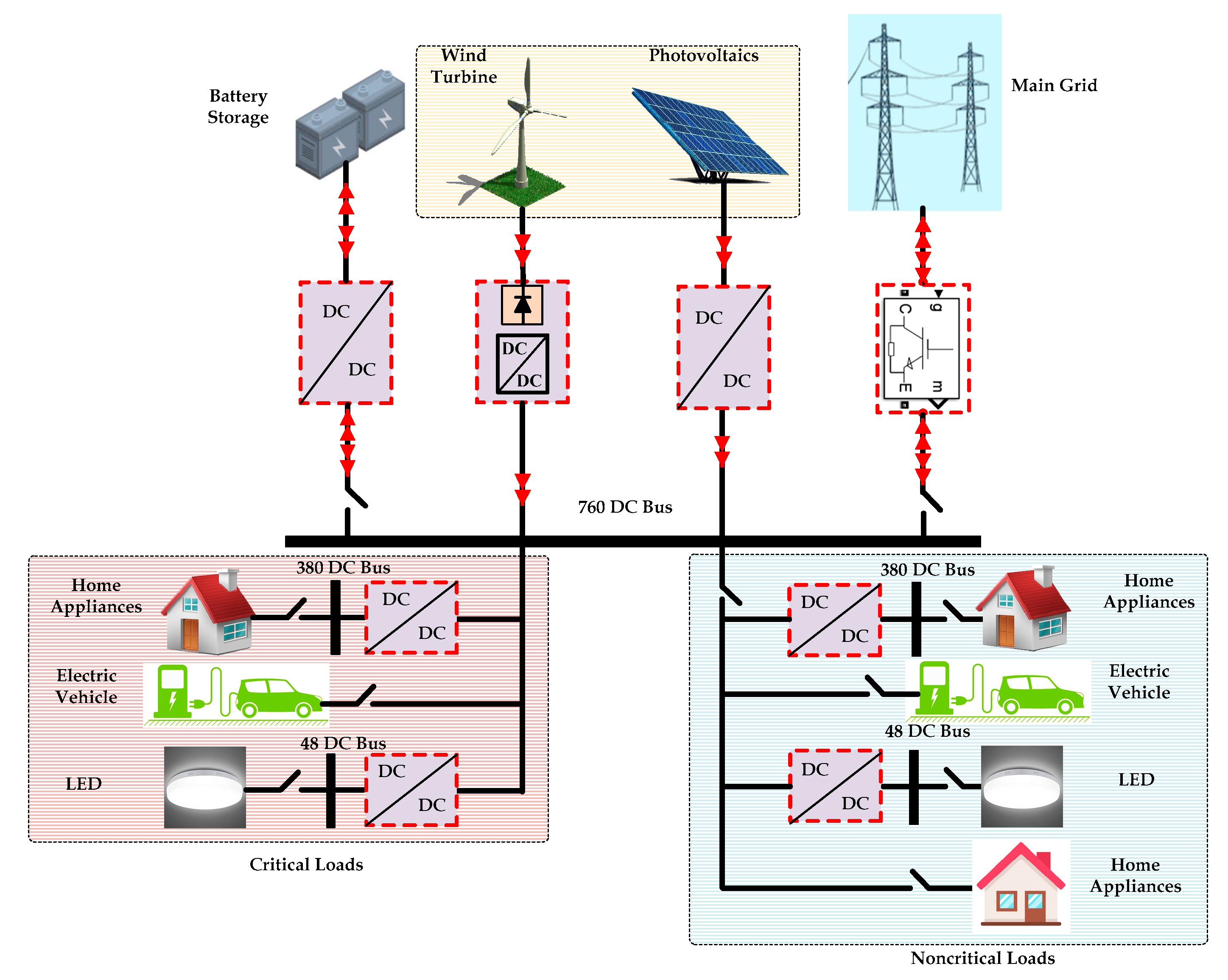
Figure 2.
The MPPT uses an IC-based PI controller.
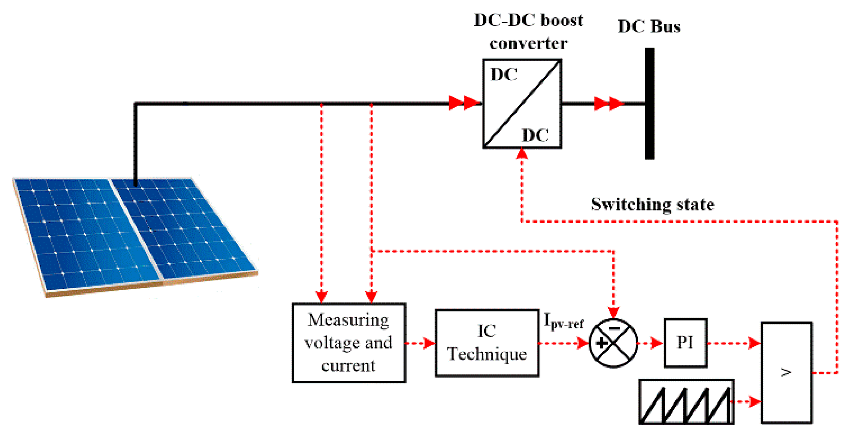
Figure 3.
Flowchart for obtaining the reference PV current based on the IC method.
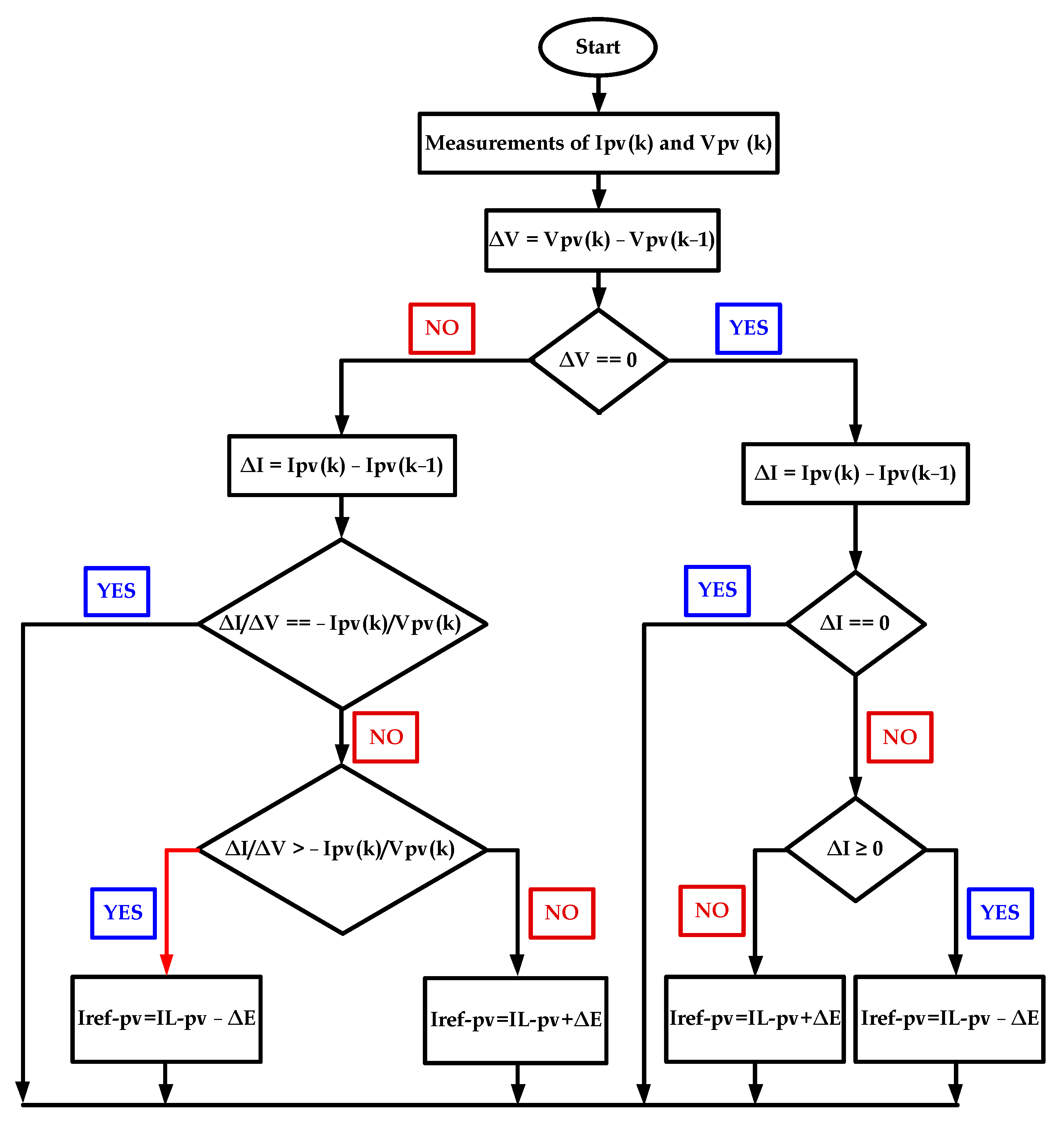
Figure 4.
Wind speed measurements for extracting MPP from the WGS.

Figure 5.
Schematic of the BES with the control.

Figure 6.
DC bus voltage control through grid-side inverter.

Figure 7.
Flowchart of the new suggested energy management strategy.
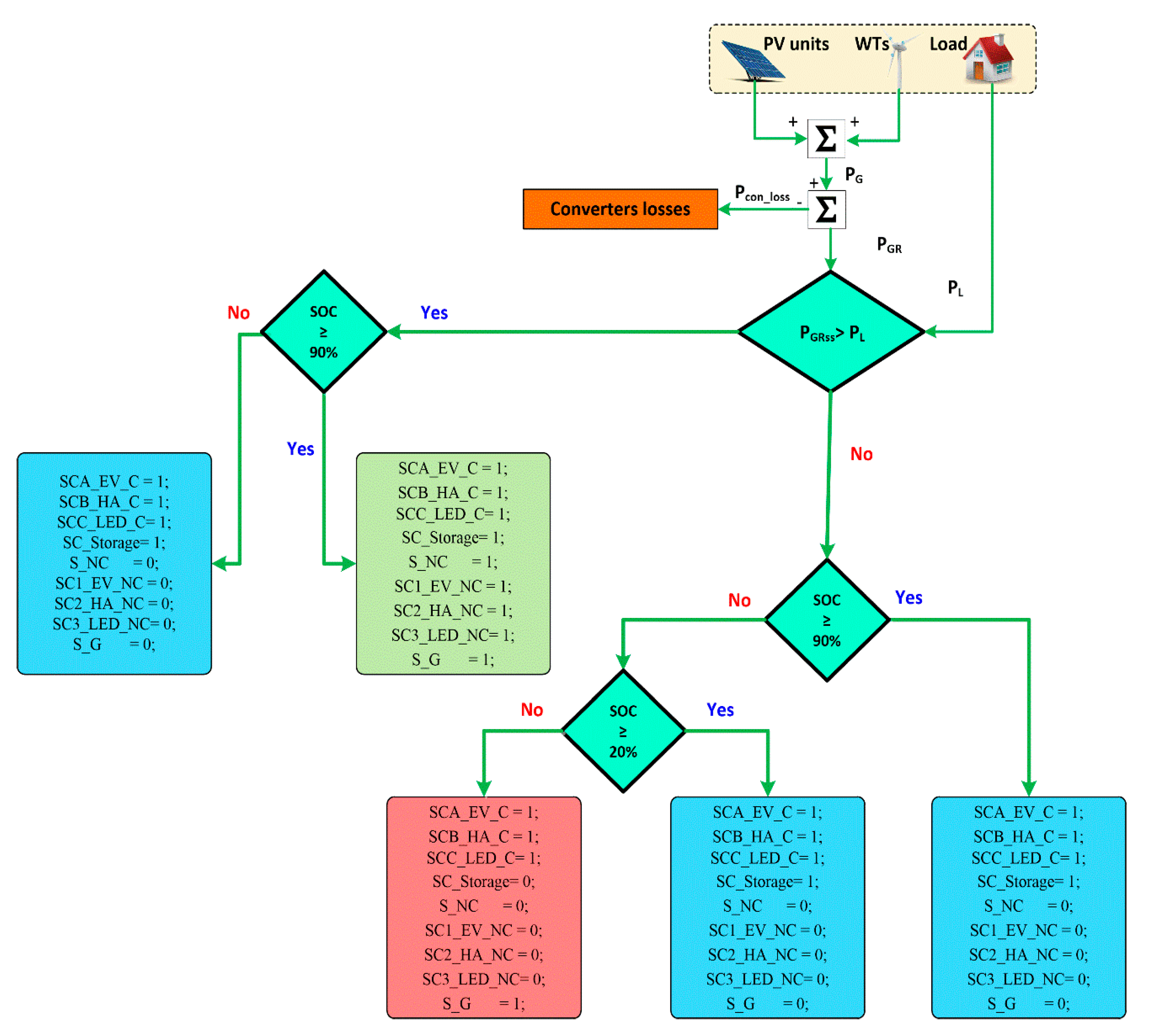
Figure 8.
Profile of solar radiation for both PI controller and constant duty.

Figure 9.
Wind power coefficient responses under both PI controller and constant duty.
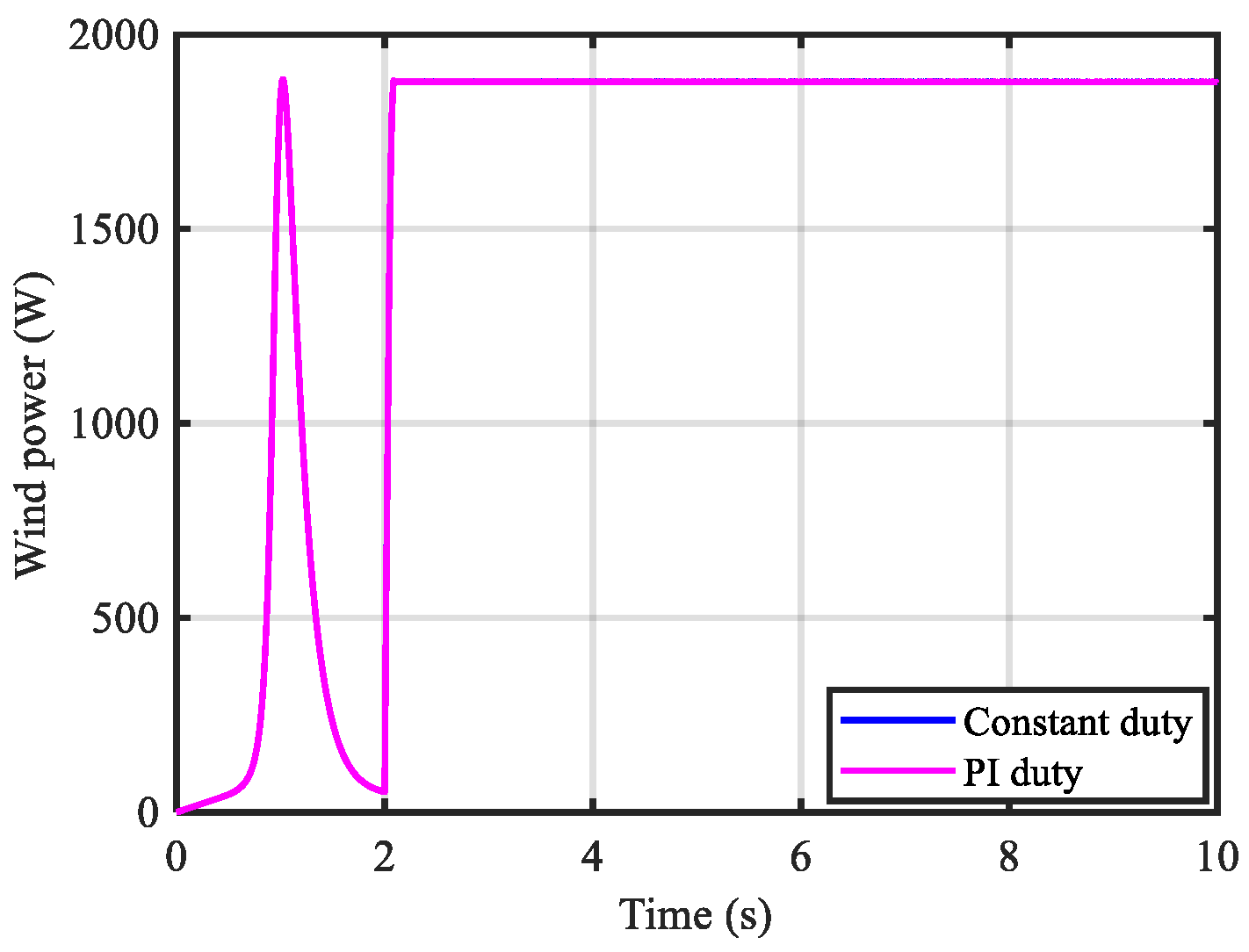
Figure 10.
PV power responses under both PI controller and constant duty.
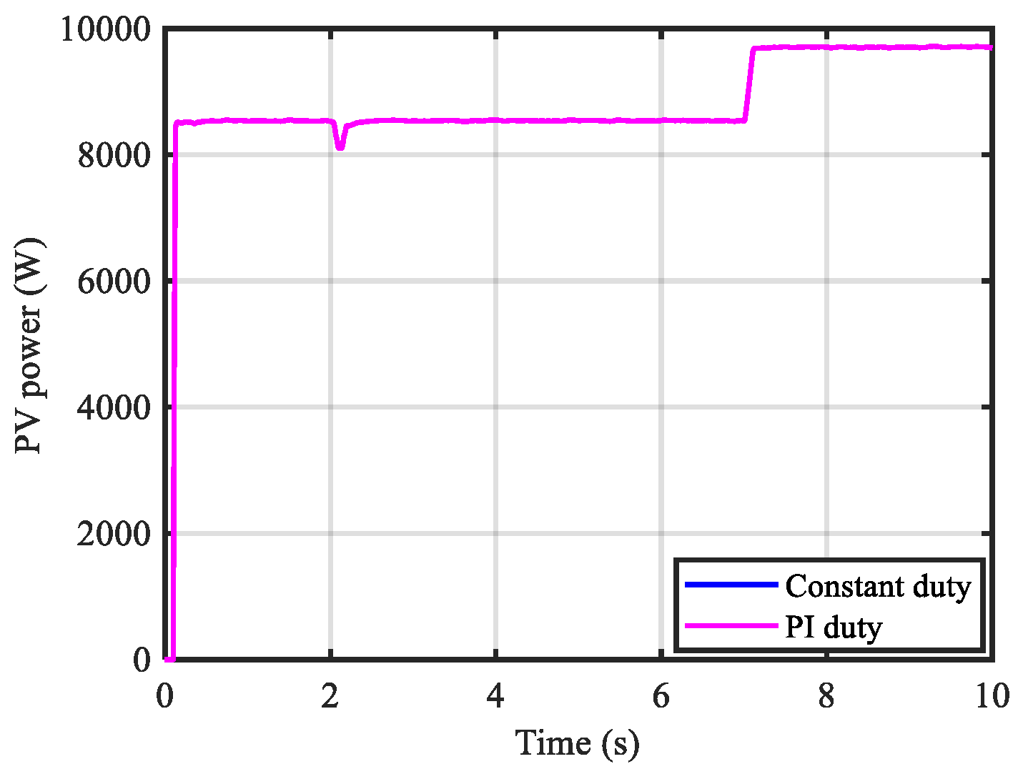
Figure 11.
Dynamic responses of 760 V under both PI controller and constant duty.

Figure 12.
Dynamic responses of 380 V under both PI controller and constant duty.

Figure 13.
Dynamic responses of 48 V under both PI controller and constant duty.
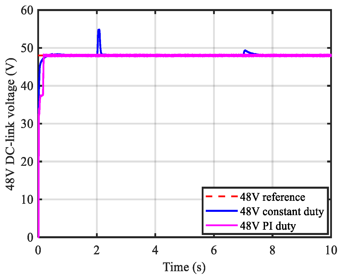
Figure 14.
Critical home power load under both PI controller and constant duty.
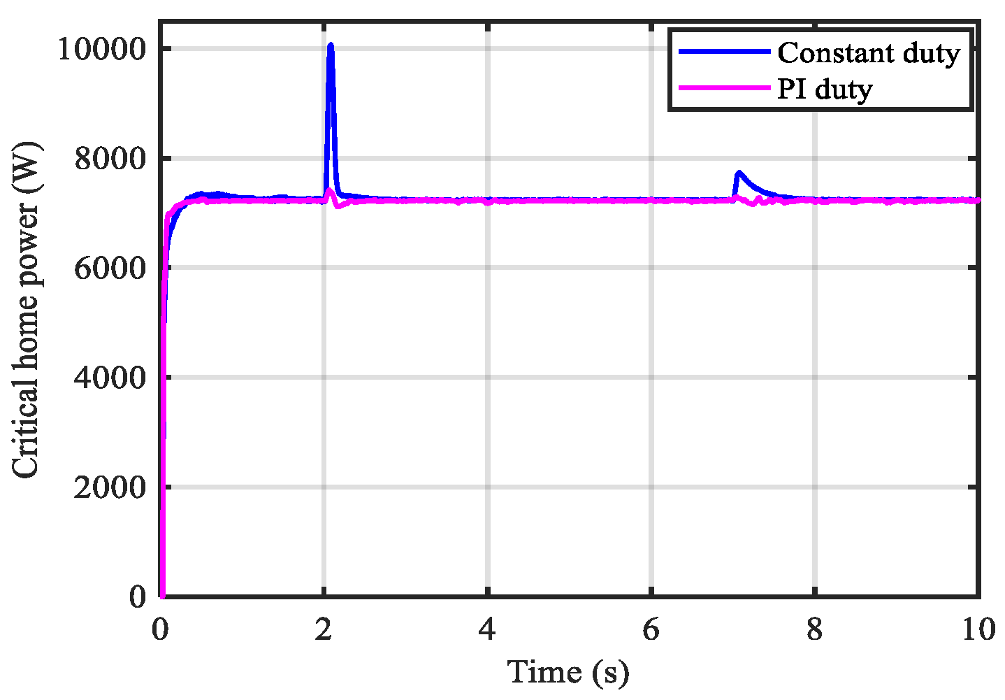
Figure 15.
Critical LED power load under both PI controller and constant duty.

Figure 16.
Critical EV power load under both PI controller and constant duty.
Figure 17.
Profile of the solar radiation for testing the proposed EMS during case 2.

Figure 18.
Produced power from PV and wind systems.
Figure 19.
Power of different critical loads under varying sun irradiance and constant wind speed considering the EMS.
Figure 19.
Power of different critical loads under varying sun irradiance and constant wind speed considering the EMS.

Figure 20.
SOC of the battery storage under varying sun irradiance and constant wind speed considering the EMS.
Figure 20.
SOC of the battery storage under varying sun irradiance and constant wind speed considering the EMS.
Figure 21.
Switching states of system components under varying sun irradiance and constant wind speed considering the EMS.
Figure 21.
Switching states of system components under varying sun irradiance and constant wind speed considering the EMS.
Figure 22.
Battery power profile under varying sun irradiance and constant wind speed.

Figure 23.
Dynamic responses of 760 V under varying sun irradiance and constant wind speed using the PI controller.
Figure 23.
Dynamic responses of 760 V under varying sun irradiance and constant wind speed using the PI controller.
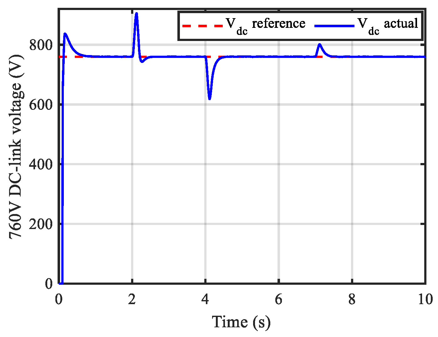
Figure 24.
Dynamic responses of 380 V under varying sun irradiance and constant wind speed using the PI controller.
Figure 24.
Dynamic responses of 380 V under varying sun irradiance and constant wind speed using the PI controller.
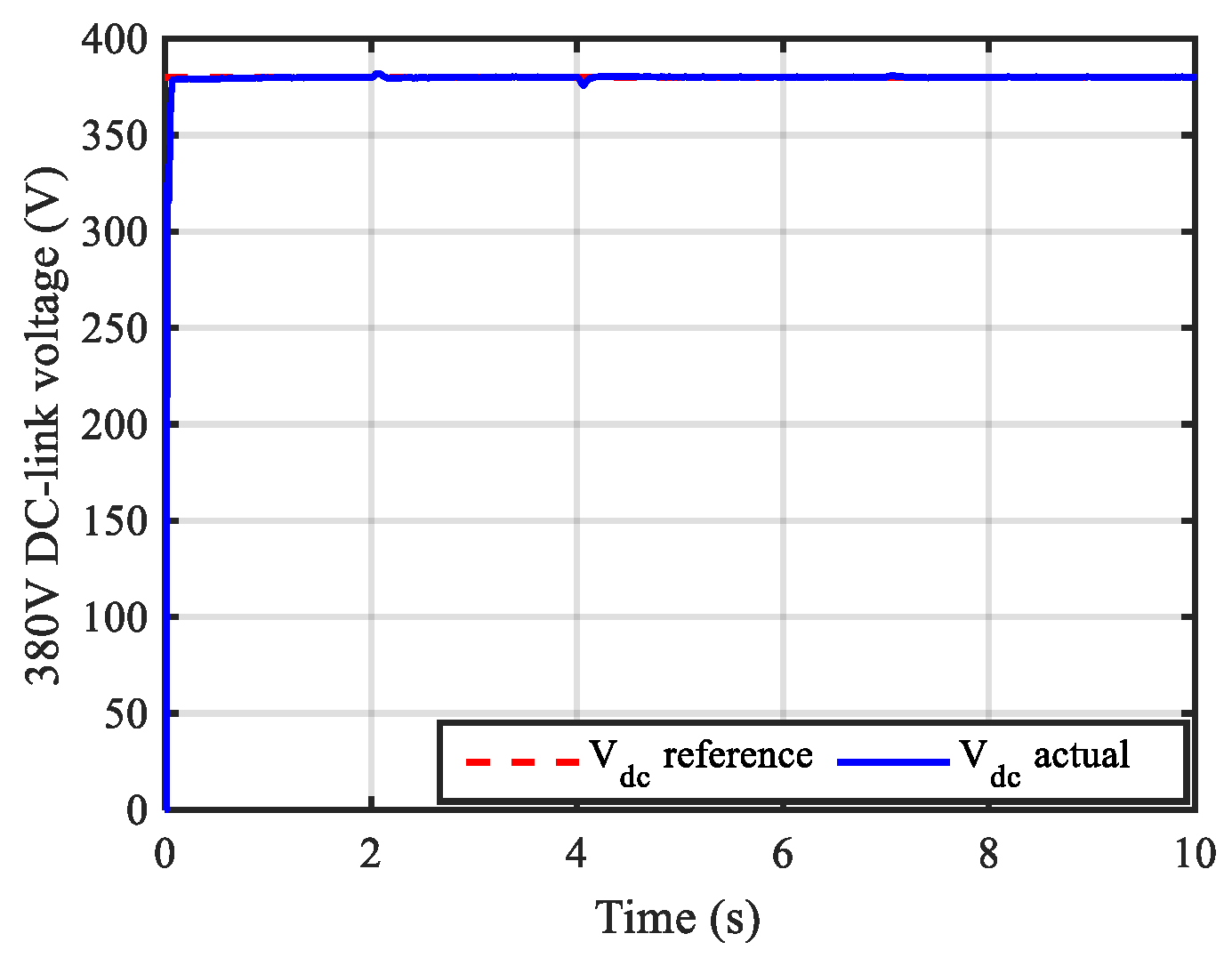
Figure 25.
Dynamic responses of 48 V under varying sun irradiance and constant wind speed using the PI controller.
Figure 25.
Dynamic responses of 48 V under varying sun irradiance and constant wind speed using the PI controller.

Figure 26.
Profile of the solar radiation for testing the proposed EMS during case 3.

Figure 27.
Profile of the wind speed for testing the proposed EMS.
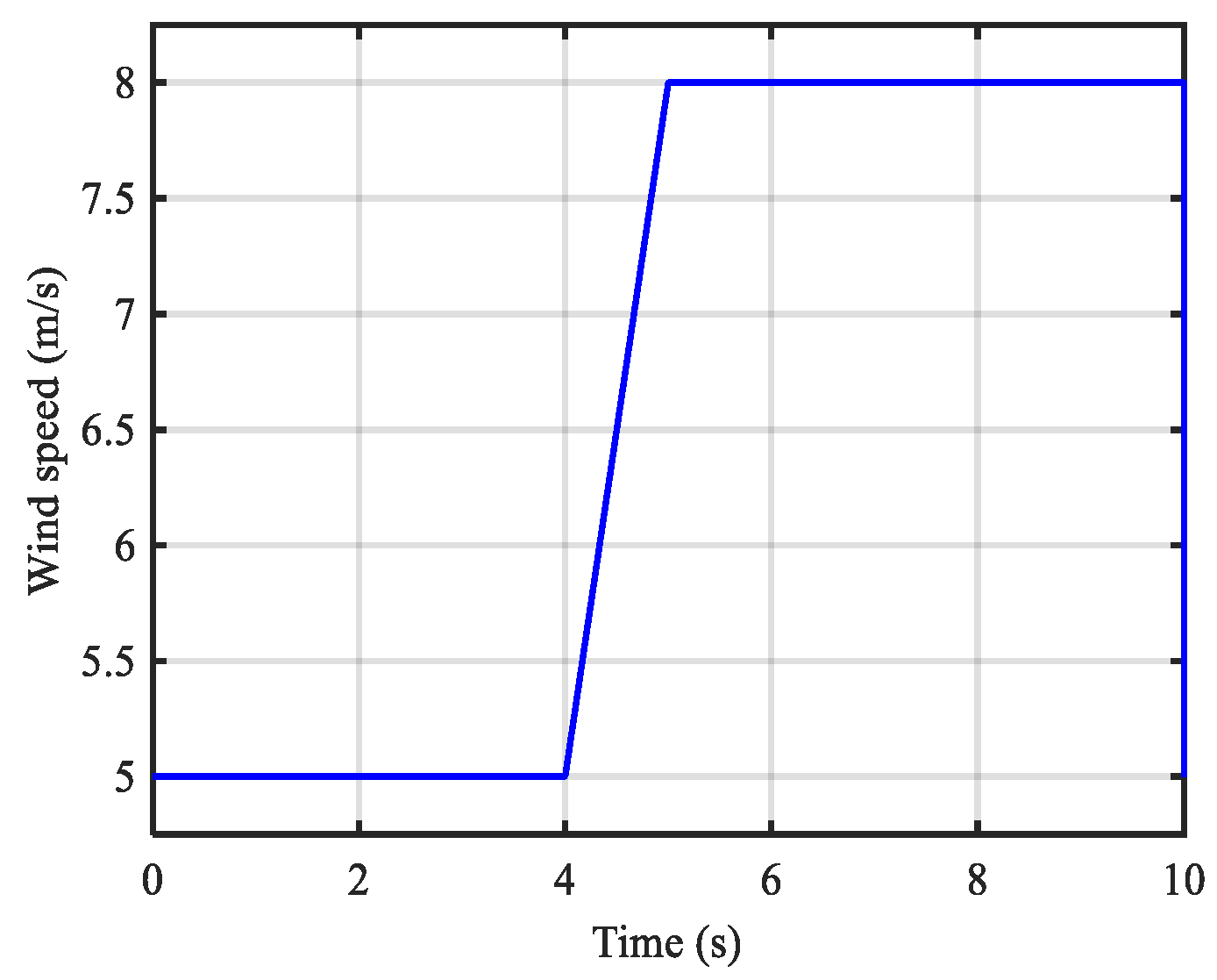
Figure 28.
Produced PV and wind power under variable solar irradiance as well as wind speed.

Figure 29.
Power of different critical loads under variable solar irradiance as well as wind speed considering the EMS.
Figure 29.
Power of different critical loads under variable solar irradiance as well as wind speed considering the EMS.
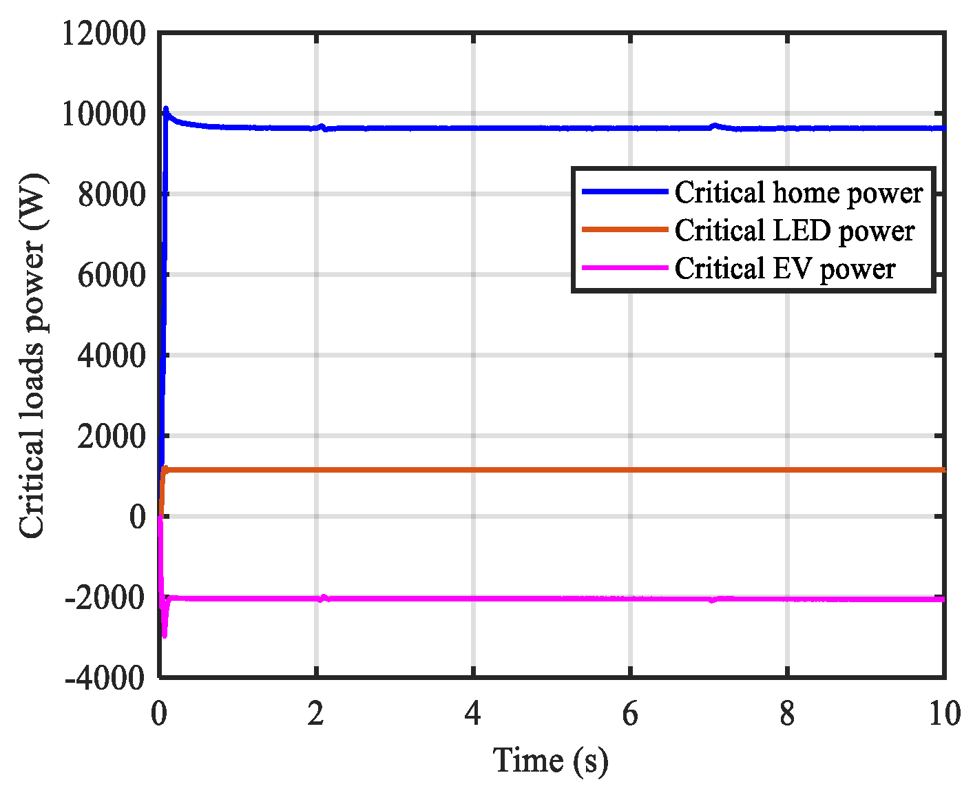
Figure 30.
SOC of the battery storage under variable solar irradiance as well as wind speed considering the EMS.
Figure 30.
SOC of the battery storage under variable solar irradiance as well as wind speed considering the EMS.
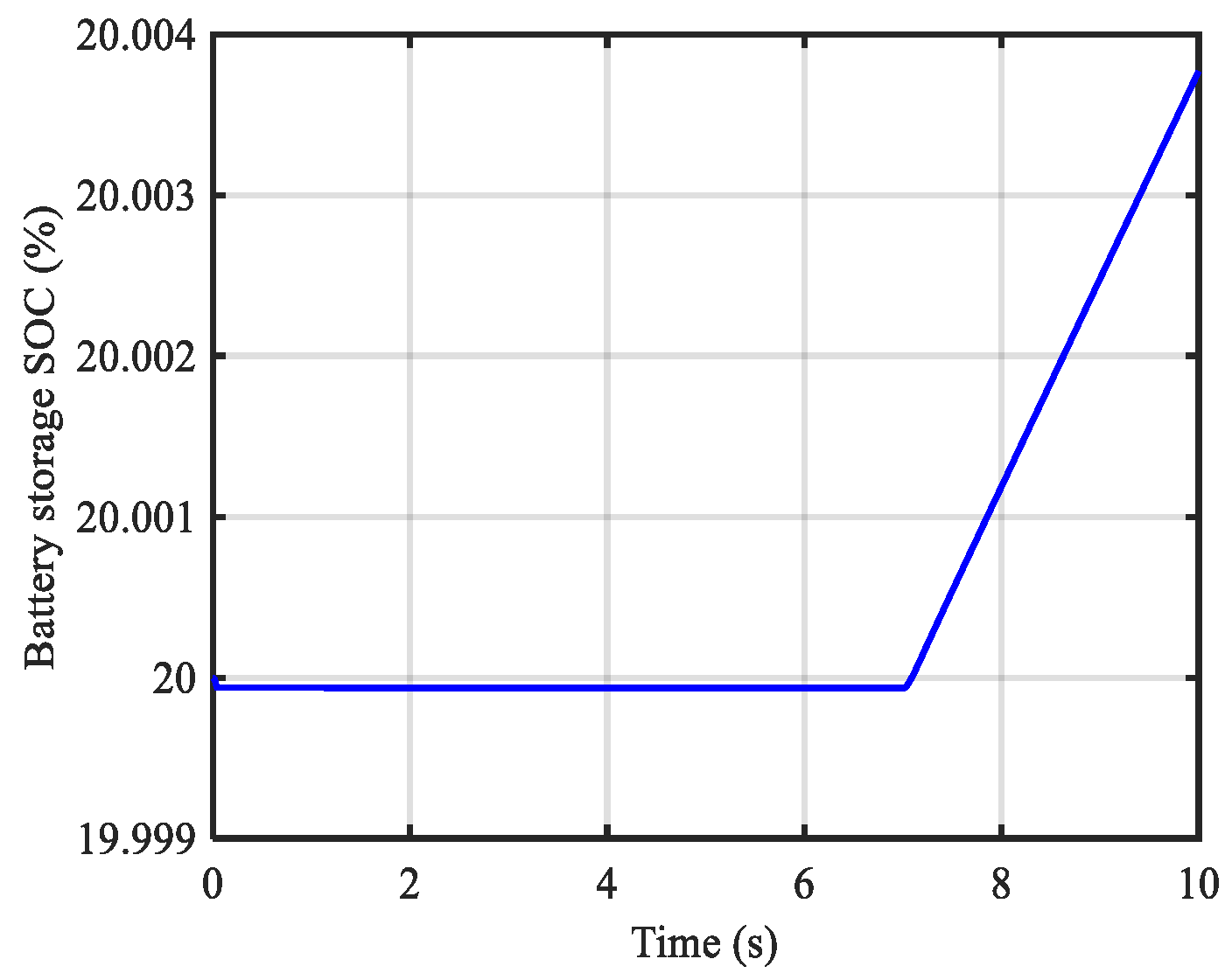
Figure 31.
Switching states of system components under variable solar irradiance as well as wind speed considering the EMS.
Figure 31.
Switching states of system components under variable solar irradiance as well as wind speed considering the EMS.
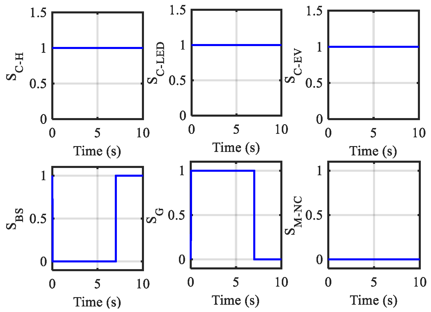
Figure 32.
Grid power profile under variable solar irradiance as well as wind speed considering the EMS.
Figure 32.
Grid power profile under variable solar irradiance as well as wind speed considering the EMS.
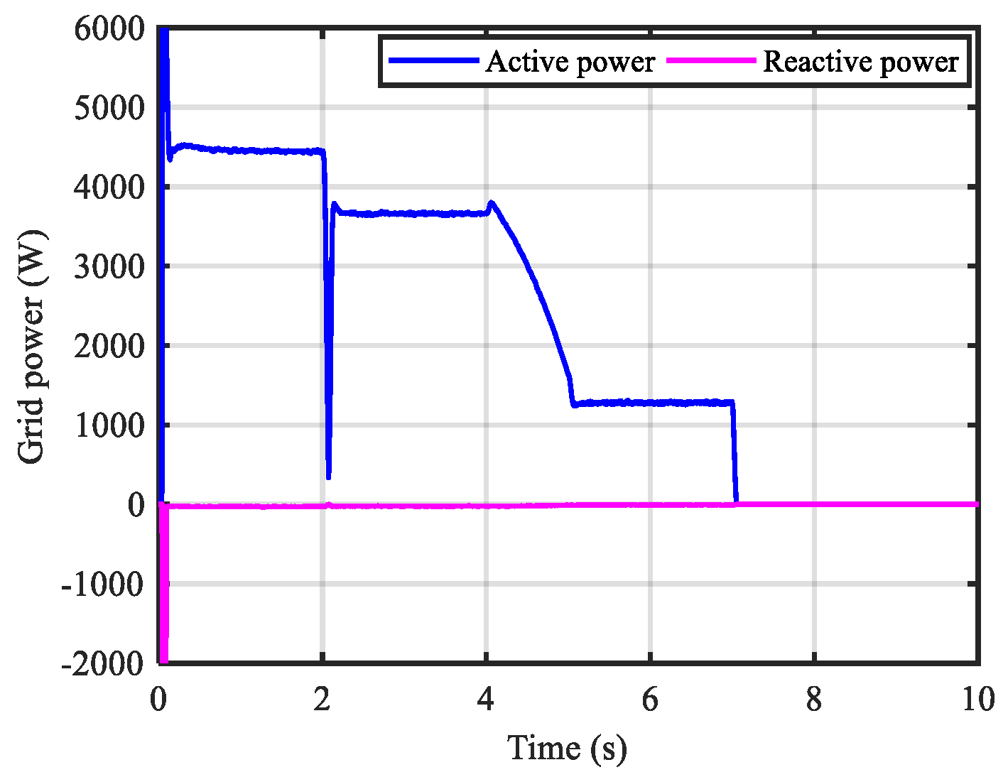
Figure 33.
Instantaneous three-phase current profile under variable solar irradiance as well as wind speed considering the EMS.
Figure 33.
Instantaneous three-phase current profile under variable solar irradiance as well as wind speed considering the EMS.

Figure 34.
Battery power profile under variable solar irradiance as well as wind speed considering the EMS.
Figure 34.
Battery power profile under variable solar irradiance as well as wind speed considering the EMS.
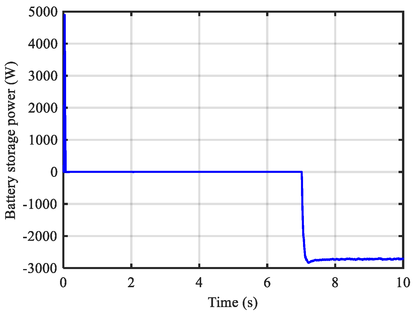
Figure 35.
Dynamic responses of 760 V under variable solar irradiance as well as wind speed using the PI controller.
Figure 35.
Dynamic responses of 760 V under variable solar irradiance as well as wind speed using the PI controller.

Figure 36.
Dynamic responses of 380 V under variable solar irradiance as well as wind speed using the PI controller.
Figure 36.
Dynamic responses of 380 V under variable solar irradiance as well as wind speed using the PI controller.
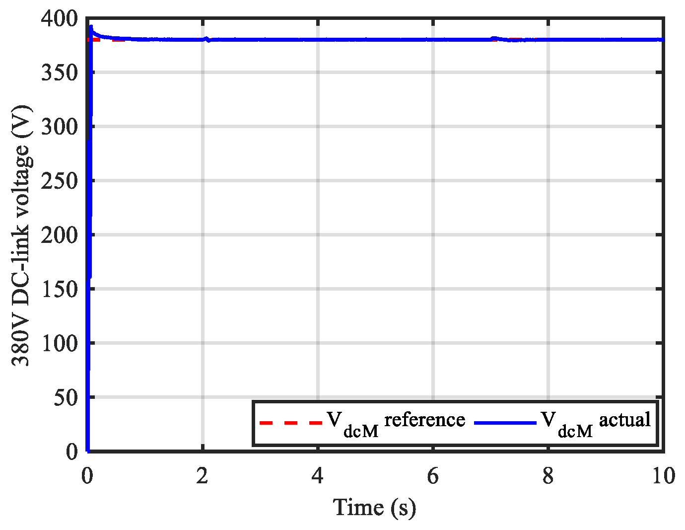
Figure 37.
Dynamic responses of 48 V under variable solar irradiance as well as wind speed using the PI controller.
Figure 37.
Dynamic responses of 48 V under variable solar irradiance as well as wind speed using the PI controller.

Figure 38.
Wind power coefficient under fixed wind speed for case 4.

Figure 39.
Produced PV and wind power under constant solar irradiance as well as wind speed.
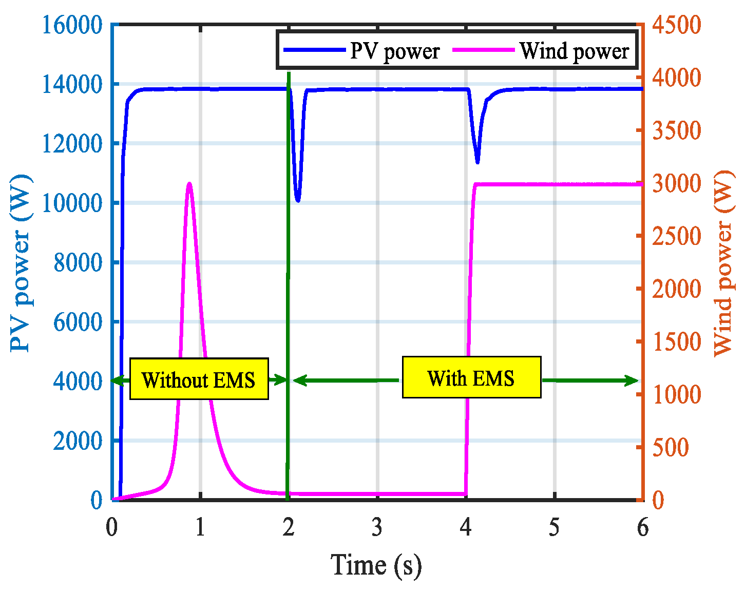
Figure 40.
Switching states of system components under constant solar irradiance as well as wind speed considering the EMS.
Figure 40.
Switching states of system components under constant solar irradiance as well as wind speed considering the EMS.
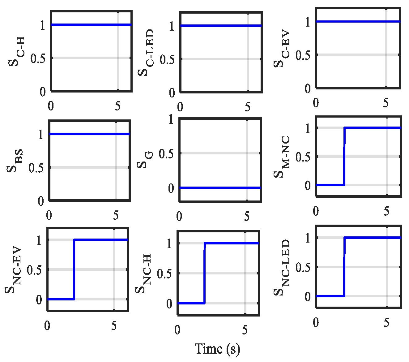
Figure 41.
Power of different noncritical loads under constant solar irradiance as well as wind speed considering the EMS.
Figure 41.
Power of different noncritical loads under constant solar irradiance as well as wind speed considering the EMS.
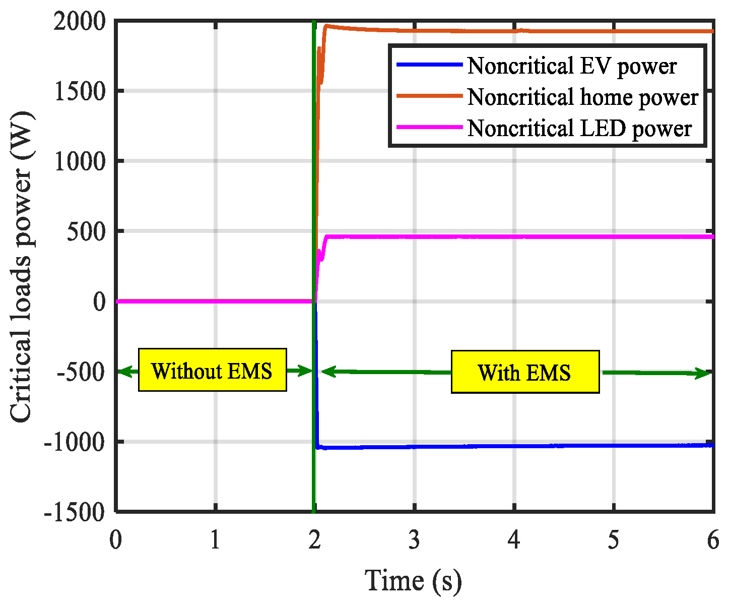
Figure 42.
Battery power profile under constant solar irradiance as well as wind speed considering the EMS.
Figure 42.
Battery power profile under constant solar irradiance as well as wind speed considering the EMS.
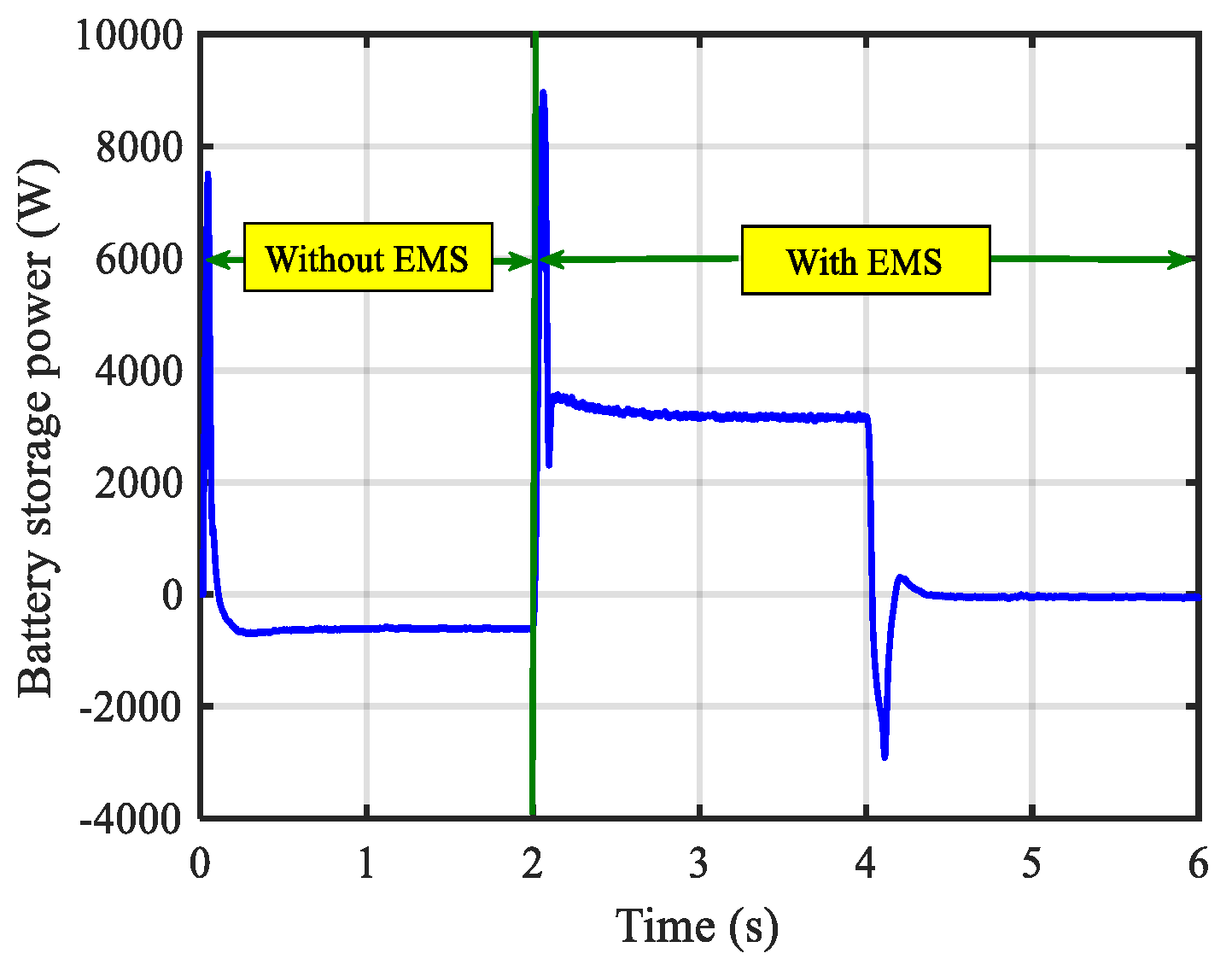
Figure 43.
SOC of the battery storage under constant solar irradiance as well as wind speed considering the EMS.
Figure 43.
SOC of the battery storage under constant solar irradiance as well as wind speed considering the EMS.
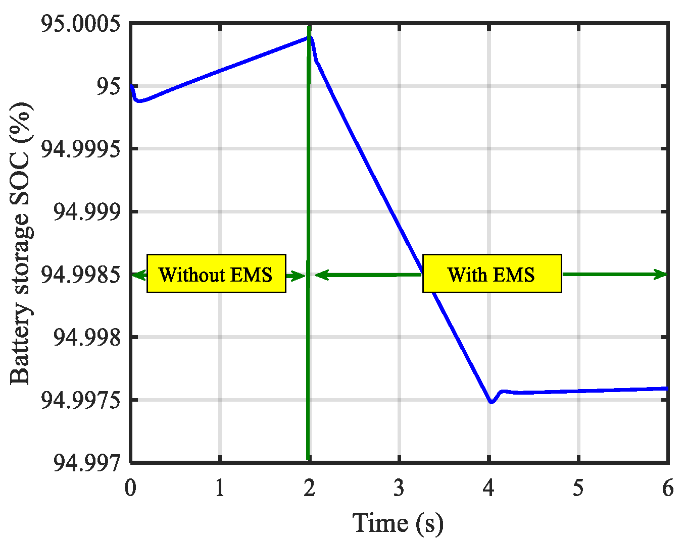
Figure 44.
Dynamic responses of 760 V under constant solar irradiance as well as wind speed using the PI controller.
Figure 44.
Dynamic responses of 760 V under constant solar irradiance as well as wind speed using the PI controller.
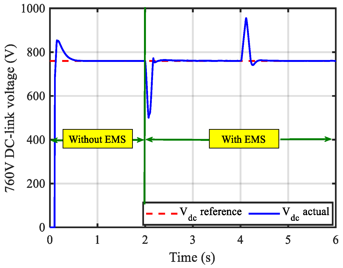
Figure 45.
Dynamic responses of 380 V under constant solar irradiance as well as wind speed using the PI controller.
Figure 45.
Dynamic responses of 380 V under constant solar irradiance as well as wind speed using the PI controller.

Figure 46.
Dynamic responses of 48 V under constant solar irradiance as well as wind speed using the PI controller.
Figure 46.
Dynamic responses of 48 V under constant solar irradiance as well as wind speed using the PI controller.
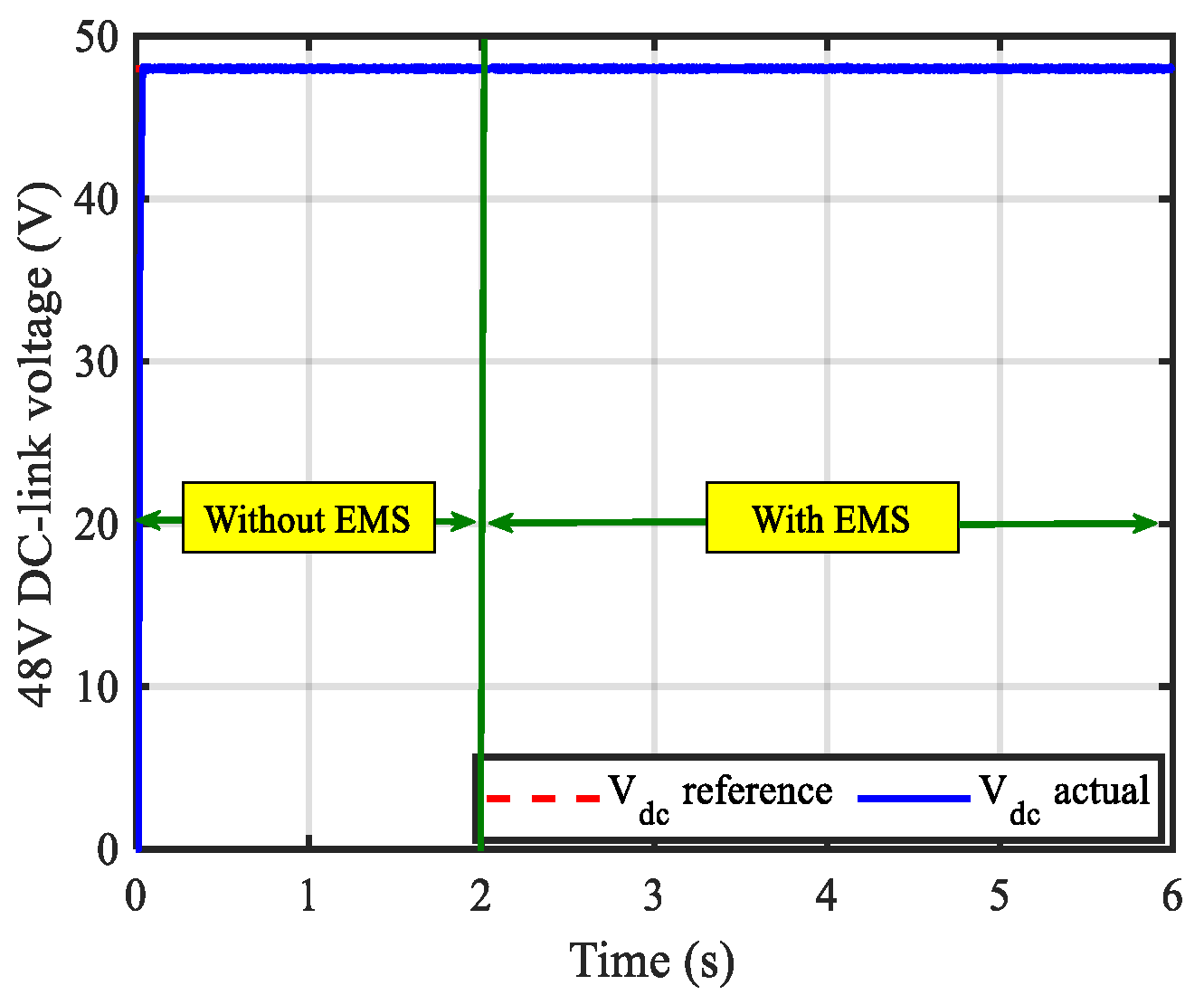
Table 1.
Installed capacities for all generation units, energy storage units, and loads.
| Parameter | Capacity |
|---|---|
| PV system | 20 kW |
| Wind energy conversion system | 6 kW |
| Battery storage system | 300 Ah or 6 kW |
| Critical home appliances | 10 kW |
| Critical electric vehicle | 3 kW |
| Critical LED | 1.5 kW |
| Noncritical home appliances | 6 kW |
| Noncritical electric vehicle | 3 kW |
| Noncritical LED | 1.5 kW |
| Main grid | Infinity |
Table 2.
Electric vehicles charging modes based on Saudi Arabia Standard.
| Charging Node | Voltage | Time for Recharging | Maximum Charging Power |
|---|---|---|---|
| Mode 1 | 230 V AC | 5 h | 3.7 kVA (3.3 kW) |
| Mode 2 | 400 V AC | 0.5 h | 44 kVA (3.3 kW) |
| Mode 3 | 300–1000 VDC | 6 min | 40–350 kWh |
Table 3.
A brief comparison of DC microgrids among the different references.
| Ref. | PV | Wind | Battery | Grid | Different Voltage Levels | DC Electric Vehicles | DC Home Appliances | DC LED | Year |
|---|---|---|---|---|---|---|---|---|---|
| [74] | √ | x | x | x | x | x | √ | x | 2016 |
| [69] | √ | x | x | x | x | x | √ | √ | 2017 |
| [75] | √ | x | √ | x | x | x | √ | √ | 2017 |
| [76] | √ | x | √ | x | x | x | √ | x | 2018 |
| [68] | √ | √ | √ | x | x | x | √ | √ | 2019 |
| [77] | √ | x | √ | √ | x | x | √ | √ | 2020 |
| [13] | √ | √ | √ | x | x | √ | x | x | 2021 |
| [78] | √ | √ | √ | x | x | x | √ | √ | 2021 |
| [14] | √ | √ | √ | √ | x | x | √ | √ | 2021 |
| [48] | √ | √ | √ | x | x | x | x | x | 2022 |
| [79] | √ | x | √ | x | x | x | x | x | 2022 |
| [80] | √ | x | √ | √ | x | √ | x | x | 2023 |
| [81] | √ | x | √ | √ | √ | x | √ | √ | 2023 |
| Proposed system | √ | √ | √ | √ | √ | √ | √ | 2023 |
| Appliance | Rated Voltage | Power Range | ||||
|---|---|---|---|---|---|---|
| 12 V | 24 V | 48 V | 380 V | 760 V | ||
| LED lamp | √ | √ | √ | 3–50 W | ||
| Fan | √ | √ | √ | 3–36 W | ||
| Refrigerator | √ | √ | √ | 40–150 W | ||
| Microwave | √ | 660–1100 W | ||||
| Coffee maker | √ | √ | 900–1200 W | |||
| Computer | √ | √ | 21–300 W | |||
| Television | √ | √ | √ | 65–120 W | ||
| Washing machine | √ | √ | 70–360 W | |||
| Iron | √ | 130–1200 W | ||||
| Rice cooker | √ | √ | 600 W | |||
| Water heater | √ | √ | √ | 1000 W | ||
| Electric kettle | √ | √ | √ | 1500 W | ||
| Air conditioner | √ | √ | 444–1300 W | |||
| Electric vehicle | √ | √ | √ | 3–350 kW | ||
Table 5.
Comparison of DC microgrids in terms of voltage levels and the tested appliances.
| Ref. | Applications | DC Output Voltages | Remarks | Year |
|---|---|---|---|---|
| [83] | Induction heating cooktop | 380 V | Although the scientists obtained much higher efficiency when the supply voltage was 380 V DC rather than 230 V AC, the study only evaluated induction heating. | 2013 |
| [84] | Lights, chargers | 48 V | Although the authors obtained a considerable reduction in THD when the supply was 48 V DC rather than 220 V AC, the DC appliances in the study were fed via a DC-DC converter. | 2015 |
| [74] | The wet-grinder and the dough-maker for net-zero energy Homes (NZEH). | 5, 48, and 120 V | Two different types of appliances have been modified for improved performance with DC. | 2016 |
| [82] | Air conditioner, microwave oven, DC fan, cloth washer, refrigerator, air cooler, water pump, electronic appliances | 48 V | The use of BLDC (brushless DC) motors is suggested for 48 V DC rotary appliances in place of universal and induction motors, by means of a DC-DC converter. | 2017 |
| [85] | DC fan, mobile charger, laptop, LED light | 48, 5, 19, and 72 V | A DC-DC converter was employed to supply the DC appliances in the study; the authors found that the efficiency was substantially higher when the supply was DC than 240 V AC. | 2018 |
| [86] | Space heating, water heating, space cooling, lighting, refrigeration, electronics, wet cleaning, cooking, computers | 24, 48, 170 and 380 V | Only a summary of recent initiatives in the area of DC power distribution system energy/efficiency. | 2019 |
| [87] | Electronic loads | 200 V | In order to provide a DC load with the necessary voltage values, this work employed a newly built DC-DC converter, the so-called two-tier converter (TTC), in the photovoltaic (PV) system. | 2022 |
| [88] | DC fan, mobile charger, laptop, LED light | 48 V | The modeling and control of non-isolated, non-inverting four-switch buck-boost (FSBB) synchronous converters, which connect to a variety of low-power electronic appliances, are expanded upon in this work. | 2023 |
| [81] | Electronic loads in every office; lighting system of the place; driver LEDs for specific area lighting. | 48, 190, and 380 V | In order to distribute power in DC using a variety of buses at various voltage levels, the multibus functionality has been upgraded. The idea is thought to be validated by a building housing the offices of instructors that also contains a charging station for electric vehicles (EVs). The system uses different topologies of power electronics converters (PECs) to perform particular jobs and provide isolation between bus and end loads. | 2023 |
| Proposed system | DC fan, mobile charger, laptop, LED light, refrigerator, washing machine, fast charger for electric vehicles | 48, 380, and 760 V | The author proposes three different levels of DC voltage to cover all kinds of DC applications. Moreover, the connection of the EV to the high DC bus voltage level for faster charging is proposed. Finally, a power management strategy to supply the critical load and noncritical load is suggested. | 2023 |
Disclaimer/Publisher’s Note: The statements, opinions and data contained in all publications are solely those of the individual author(s) and contributor(s) and not of MDPI and/or the editor(s). MDPI and/or the editor(s) disclaim responsibility for any injury to people or property resulting from any ideas, methods, instructions or products referred to in the content. |
© 2023 by the authors. Licensee MDPI, Basel, Switzerland. This article is an open access article distributed under the terms and conditions of the Creative Commons Attribution (CC BY) license (https://creativecommons.org/licenses/by/4.0/).
Share and Cite
MDPI and ACS Style
Elmorshedy, M.F.; Subramaniam, U.; Mohamed Ali, J.S.; Almakhles, D. Energy Management of Hybrid DC Microgrid with Different Levels of DC Bus Voltage for Various Load Types. Energies 2023, 16, 5438. https://doi.org/10.3390/en16145438
AMA Style
Elmorshedy MF, Subramaniam U, Mohamed Ali JS, Almakhles D. Energy Management of Hybrid DC Microgrid with Different Levels of DC Bus Voltage for Various Load Types. Energies. 2023; 16(14):5438. https://doi.org/10.3390/en16145438
Chicago/Turabian StyleElmorshedy, Mahmoud F., Umashankar Subramaniam, Jagabar Sathik Mohamed Ali, and Dhafer Almakhles. 2023. "Energy Management of Hybrid DC Microgrid with Different Levels of DC Bus Voltage for Various Load Types" Energies 16, no. 14: 5438. https://doi.org/10.3390/en16145438
Note that from the first issue of 2016, this journal uses article numbers instead of page numbers. See further details here.