Article

Coupled Hydromechanical Modeling and Assessment of Induced Seismicity at FWU: Utilizing Time-Lapse VSP and Microseismic Data

New Mexico Tech-PRRC, 801 Leroy Place, Socorro, NM 87801, USA
*
Author to whom correspondence should be addressed.
Energies 2023, 16(10), 4163; https://doi.org/10.3390/en16104163
Submission received: 28 March 2023 / Revised: 9 May 2023 / Accepted: 9 May 2023 / Published: 18 May 2023
(This article belongs to the Special Issue Forecasting CO2 Sequestration with Enhanced Oil Recovery II)

Abstract

:
The objective of this work is to utilize integrated geomechanics, field vertical seismic profile (VSP) and microseismic data to characterize the complex subsurface stress conditions at the Farnsworth Unit (FWU). The model is based on a five-spot sector model extracted from a primary geomechanical model. The five-spot well injection pattern is characterized by extensive reservoir characterization data, such well logs, extracted cores and borehole geophone data, to facilitate the detailed examination of stress changes and microseismic event occurrences. The study utilizes field vertical seismic volumes acquired from the injection well 13-10A. The seismic volumes successfully provided snapshots of the behavior of the reservoir at distinct times. The use of VSP and microseismic data provided direct and indirect estimates of the dynamic stress changes occurring in the overburden, reservoir and underburden rock formations. In order to illuminate the stress regions and identify rocks that have undergone inelastic failure, microseismic event occurrences were utilized. Microseismic activity has been detected at the FWU; further study of its locations, timing, and magnitude was needed to deduce the nature of the changing stress state. The results of the study revealed that microseismic events were successfully modeled within the Morrow B formation. Moment magnitudes of seismic events were within the same magnitudes for events in the reservoir, suggesting the suitability of the model. The results of the study showed that the computed moment magnitudes for seismic events were insignificant to warrant safety concerns. The study findings showed the usefulness of coupled hydromechanical models in predicting the subsurface stress changes associated with CO2 injection. The knowledge gained from this study will serve as a guideline for industries planning to undertake underground CO2 storage, and characterize the subsurface stress changes.

1. Introduction

The concentration of atmospheric CO2 is steadily on the rise and a significant contributing factor is the worldwide consumption of fossil fuels. The burning of fossils fuels, especially with the release of carbon dioxide, is having adverse effects on the climate. Harsh climate conditions, such as increased droughts, intense heat waves, wildfires and floods, are anticipated to occur. Carbon dioxide is responsible for 64% of the enhanced greenhouse effect, making it a target for geologic sequestration [1]. Carbon dioxide (CO2) sourced from the power and industry sectors forms 60% of the total CO2 emissions [2]. Instead of releasing these greenhouse gases into the atmosphere, it is captured and utilized for recovering oil and subsequently stored in geologic formations. Carbon capture technologies play vital roles in reducing CO2 emissions. In addition, monitoring strategies are employed to ensure the safe storage of the greenhouse gas and to avoid any potential leakage to the surface. With the adoption of the Section 45Q Tax Incentive, participation in carbon capture and storage techniques has gained increasing attention [3]. The objective of the Federal 45Q tax credit is to incentivize the implementation of carbon capture and storage (CCS) technologies which entail the sequestration of carbon dioxides in underground reservoirs [4]. Injecting CO2 into matured oil and gas fields has been identified as a viable method for enhanced oil recovery [5]. However, the capture and storage of significant quantities of CO2 raises possible geomechanical concerns with channels developed in sealing rocks serving as potential conduits for injected CO2. The creation of fractures/faults in rocks is accompanied by the release of seismic energy. Microseismic events recorded illuminate the locations of seismic energy release caused by variations in stress. Examining the timing, location, and magnitudes of microseismic occurrences can provide sufficient information into the dynamic and complex stress field at the Farnsworth Field Unit (FWU). The production and geophysical dataset utilized in this study is from the ongoing CO2-Enhanced oil recovery (EOR) operations at the FWU. The FWU carbon, capture, utilization and storage (CCUS) project forms part of the Southwest Regional partnership on carbon sequestration (SWP). This study supports the SWP tasks in developing numerical reservoir simulation models to decrease the potential seismic hazard associated with CO2 injection, and improve the prediction of stress changes in a reservoir undergoing CO2-EOR. The geomechanical impacts of stress fluctuations in and around the reservoir were investigated using a coupled hydromechanical simulation model.

2. Background Study

Numerous studies have been conducted on the effectiveness of carbon capture and storage (CCS) and CCUS technologies to mitigate atmospheric CO2 emissions. CO2 captured from industrial facilities are injected to enhance oil recovery or stored in deep geologic formations [6]. Despite the successful implementation of CCS technologies, there are still concerns about potential leakages of CO2 into underground water sources. Additionally, the high cost of deploying carbon capture and storage (CCS) technologies means that there is still some apprehension regarding its commercialization. Even though geologic sites have stored oil and gas for centuries, they are often screened to assure the safe and lasting containment of CO2 [7]. The production/injection of fluids, such as CO2, and water, is known to alter the formation pore pressures which impacts the stress distribution in the overburden, underburden and reservoir rock. Depending on the geology of the area, formation geomechanical properties, volumes and rates of fluid injection, there may be a potential for injection-induced seismicity [8,9].
In recent decades, high magnitude earthquakes have occurred due to subsurface activities. For instance, an earthquake of magnitude Mw 5.0 occurred in the Delaware Basin on March 2020 as a result of wastewater disposal. Despite hydraulic fracturing operations and hydrocarbon production on the field, a study conducted by Skoumal et al. [10] attributed the primary cause of the induced seismicity to wastewater injection in the Devonian formation. The deep Devonian formation is in close proximity to the crystalline basement. The absence of an interbedded formation between the Devonian formation and the crystalline basement allows the triggering motion of high injection wells to be transferred to deeper fault structures. Injecting fluids at high rates into the deeper Devonian formation increases the tendency of matured faults in the basement rock to slip, resulting in increased seismic activities. Similar findings of a high magnitude earthquake (Mw 5.8) happened in neighboring Oklahoma [11]. Studies showed that the majority of the microseismic events were related to deep wastewater injection. Although wastewater was injected heavily into a fault zone, which could be a contributor to the earthquake occurrences, the main contributor to the observed seismicity was the triggering of faults in the basement rock neighboring the injection zone. Additionally, active faults in the sedimentary strata were intersecting the basement crystalline rock. The opposite situation can be observed in the rock stratigraphic sequence in the Farnsworth Unit. In the FWU, there exists a lower shale formation beneath the Morrow B sandstone. The presence of an interbedded shale layer restricts vertical flow and pressure response from the injection interval to the Pre-Cambrian basement. Although microseismic events have been observed, they are of smaller magnitudes.
Microseismic events that occur during hydraulic fracturing activities in the oil and gas industry are primarily caused by shear slippage on pre-existing faults and fractures. However, the mechanisms and factors controlling fault reactivation during hydraulic fracturing are not fully understood [12]. To address this knowledge gap, Zoback and Lund Snee [13] investigated the conditions where fault slippage occurs, considering pore pressure perturbation, stress state and fracture orientation. It was revealed from the study that as pressure increases, more poorly oriented planes tend to slip. However, the tendency for a fault to slip depends on the fault strike to the σ h m a x direction. At the FWU, McMillan [13] reported the current stress state of the Morrow B formation as a normal faulting regime with σ v > σ h m a x > σ h m i n , where σ v is the vertical principal stress and σ h m i n is the minimum horizontal principal stress. Information on the orientation of the stress field was inferred from the ultrasonic borehole image (UBI) data. The azimuth of the maximum horizontal stress is determined to be 108 ( ± 4 ) degrees. Knowledge of the orientation of the maximum horizontal stress was based on the drilling induced fractures in the Morrow Shale Formation below the Morrow B Formation. The orientation of the minimum horizontal stress direction was measured at 115–120 degrees, according to the Oil-Based Micro Imager (OBMI) and Ultrasonic Borehole Imager (UBI) logs. As a result, the finalized stress initialization incorporates a minimum horizontal stress azimuth of 20 degrees. Geomechanical models are constructed to model the plastic deformation and pore pressure distribution. To study the occurrences of induced seismicity, Tutuncu et al. [9] utilized coupled geomechanics and fluid flow models to predict the potential for microseismic occurrences in the Eagle Ford formation during a hydraulic fracturing operation. The formation of interest had existing faults and the impact of the presence of faults at distances away from the injector wells were studied. The study revealed that high injection rates were considered as critical factors to the occurrence of induced seismicity. Again, faults located at larger distances from the injection site experienced lower shear stresses, which resulted in reduced fault reactivation. Chen et al. [14] examined the occurrence of seismic events in the Azle area, North Texas, from November 2013 through April 2014. The authors performed a geomechanical simulation study of the overburden to the crystalline base rock, analyzing the contribution of oil and gas operations to seismic events. According to the study, pore pressures did not increase within the basement fault; however, noticeable seismicity was recorded at the basement formation. A plausible explanation for the observable seismic events was the unbalanced loading on different sides of the Azle fault, leading to an accumulation of plastic strain changes at the base rock.
At the FWU, several numerical simulation studies have been performed by researchers in the Southwest Regional Partnership (SWP) team to monitor the migration of injected CO2 in the Morrow B sandstone during an active CO2-WAG injection. Monitoring was performed by examining the changes in the reservoir elastic and petrophysical properties with CO2 injection. The competency of the simulation model results was enhanced by the integration of acquired field geophysical data and results from laboratory experiments. For instance, Adu-Gyamfi et al. [15] conducted a simulation study to examine the chemical and mechanical impact on the caprock integrity as a result of CO2 injection. The simulation study indicated that the caprock maintained its elastic properties for the forecasted years despite changes in the formation petrophysical properties and CO2 interactions in the caprock. Additionally, Acheampong et al. [16] performed a fluid substitution modeling to investigate the contribution of fluid saturation changes to the time-lapse velocity responses using a site-specific rock physics modeling. Although seismic velocities are widely known to be sensitive to stress changes, the study focused solely on the impact of fluid change to the saturated rock elastic and seismic properties. McMillan [13] developed a time-lapse VSP integration workflow that utilizes field VSP data to calibrate subsurface stress changes. The work examined how induced stress changes from CO2-WAG injection could potentially impact the seismic velocities inverted from the field VSP data. The study showed that time-lapse acoustic measurements were suitable for calibrating the subsurface stress changes. Although calibration of the geomechanical model was performed through time-lapse VSP profiling to estimate the stress changes, the study did not model the occurrence of microseismic events, which are indications of stress changes in the subsurface. Again, defining the subsurface stress state with the help of a numerical simulation model is non-unique. Multiple realizations of the mechanical earth model (MEM) can be generated. These realizations are valid depictions of the subsurface, although their orientation and magnitude of stresses may differ.
To address the above-mentioned challenges and reduce the solution non-uniqueness of the model, a robust integration framework that combines fluid flow models, coupled geomechanics, and microseismic data were utilized in an effort to improve the prediction of stress changes within a reservoir undergoing CO2-EOR. Additionally, we confirmed that the method of using inelastic failure was successful in modeling the microseismic events.

3. Field Description

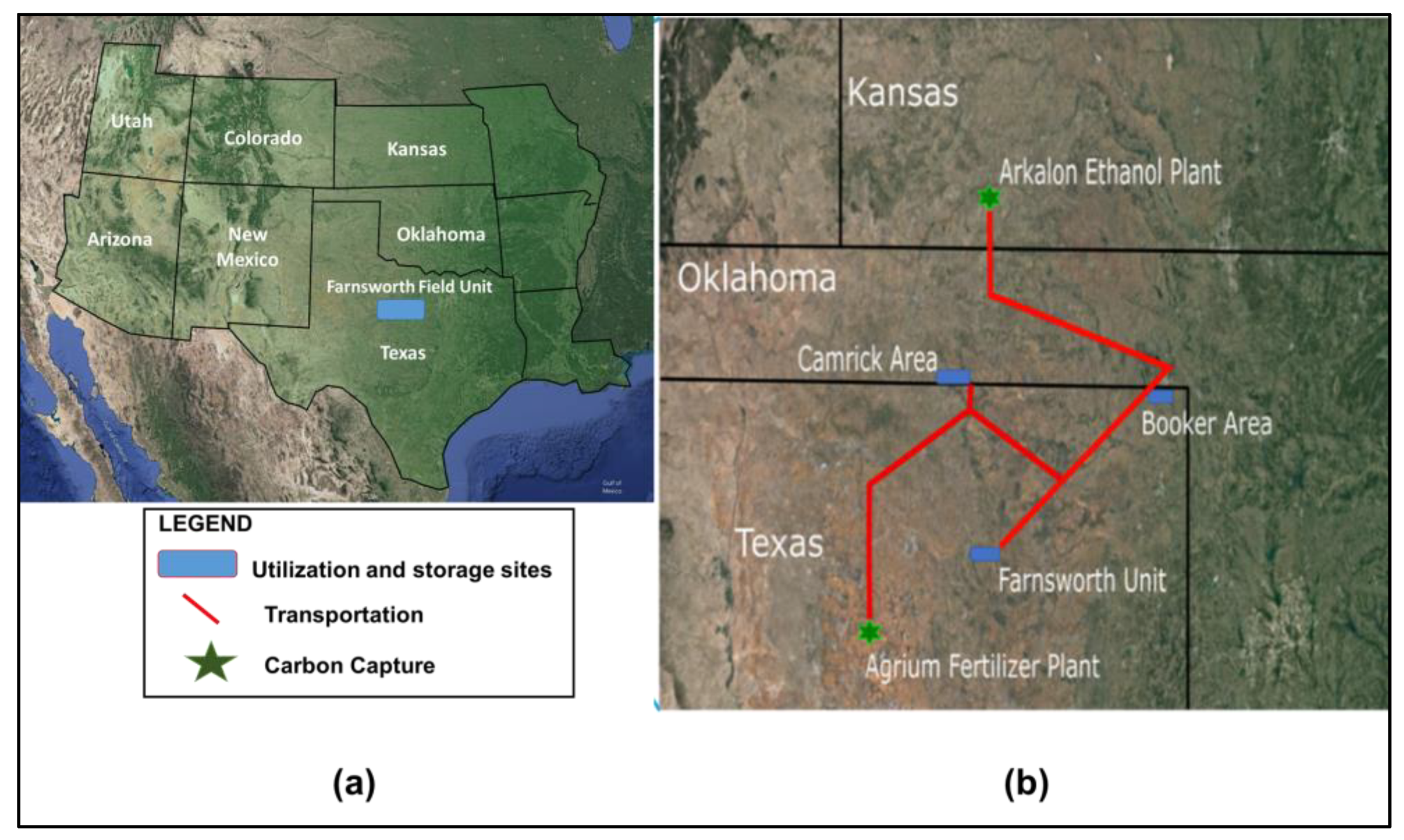
3.1. Site Description

The Southwest Regional Partnership on Carbon Sequestration (SWP) is one of the seven regional partnerships sponsored by the US Department of Energy and National Technology Laboratory (NETL) to evaluate the large-scale feasibility of permanently sequestering CO2 in geologic formations. The study site for the SWP is the Farnsworth Field Unit, located in the Western Anadarko basin. The primary target for hydrocarbon production and CO2 sequestration is the operationally named Morrow B formation [17]. The FWU field has been under primary and secondary recovery stages and currently undergoing an active CO2 water-alternating-gas (WAG) injection. The FWU CO2 WAG injection commenced in 2010 with anthropogenic CO2 sourced from the Arkalon Ethanol Plant in Liberal Kansas, and the Agrium Fertilizer Plant in Texas. Currently, CO2 is supplied mainly from the Arkalon Ethanol Plant [18]. A probabilistic study performed by [19], using the field’s relative permeability curves, showed that the Morrow B formation can store at least 7.81 MMtons of CO2 with the highest estimate of CO2 storage being 40.52 MMtons. Presently, more than 1 million metric tons of CO2 have been sequestered in the Morrow B formation. Figure 1 shows the location of the FWU in the Anadarko basin.

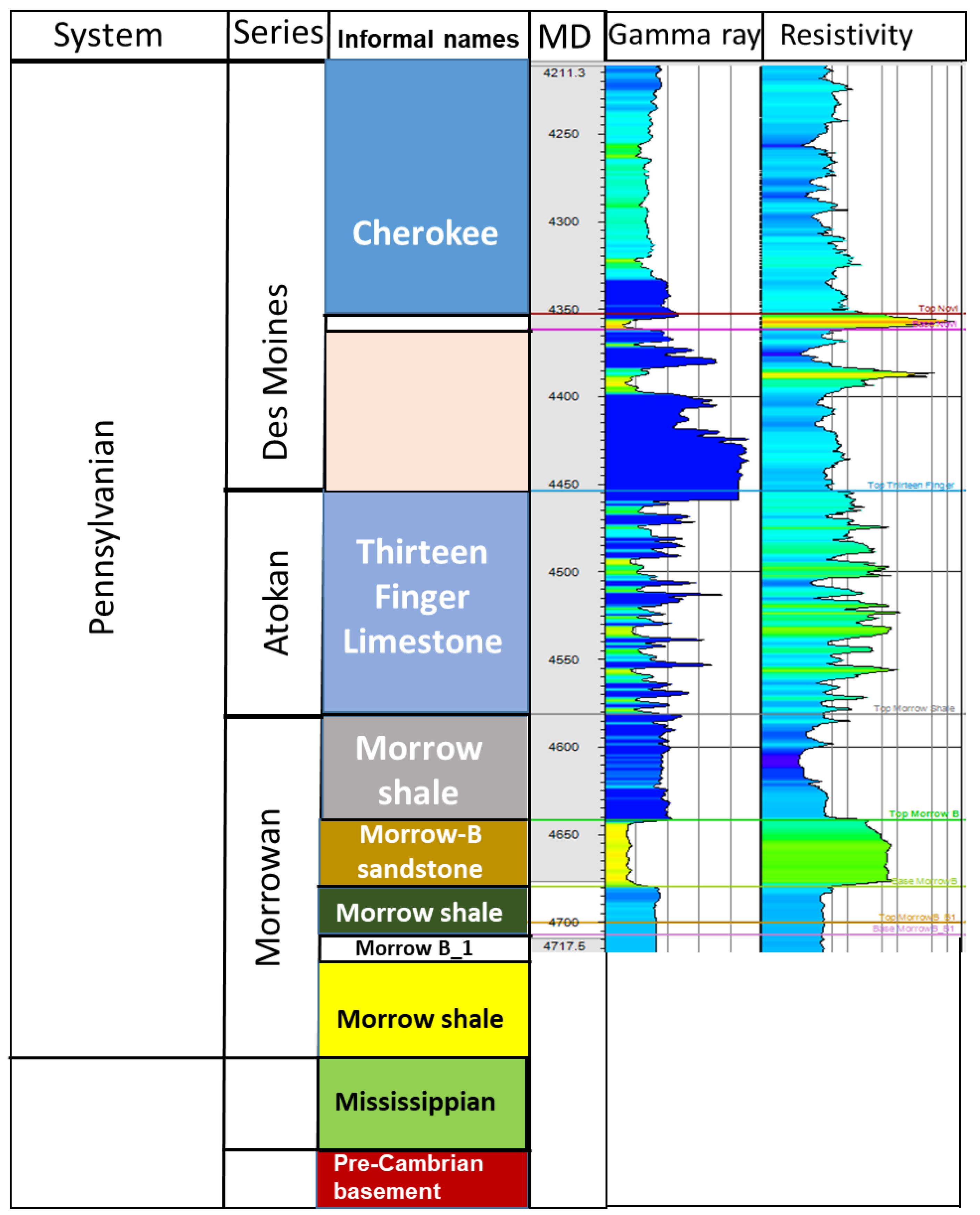
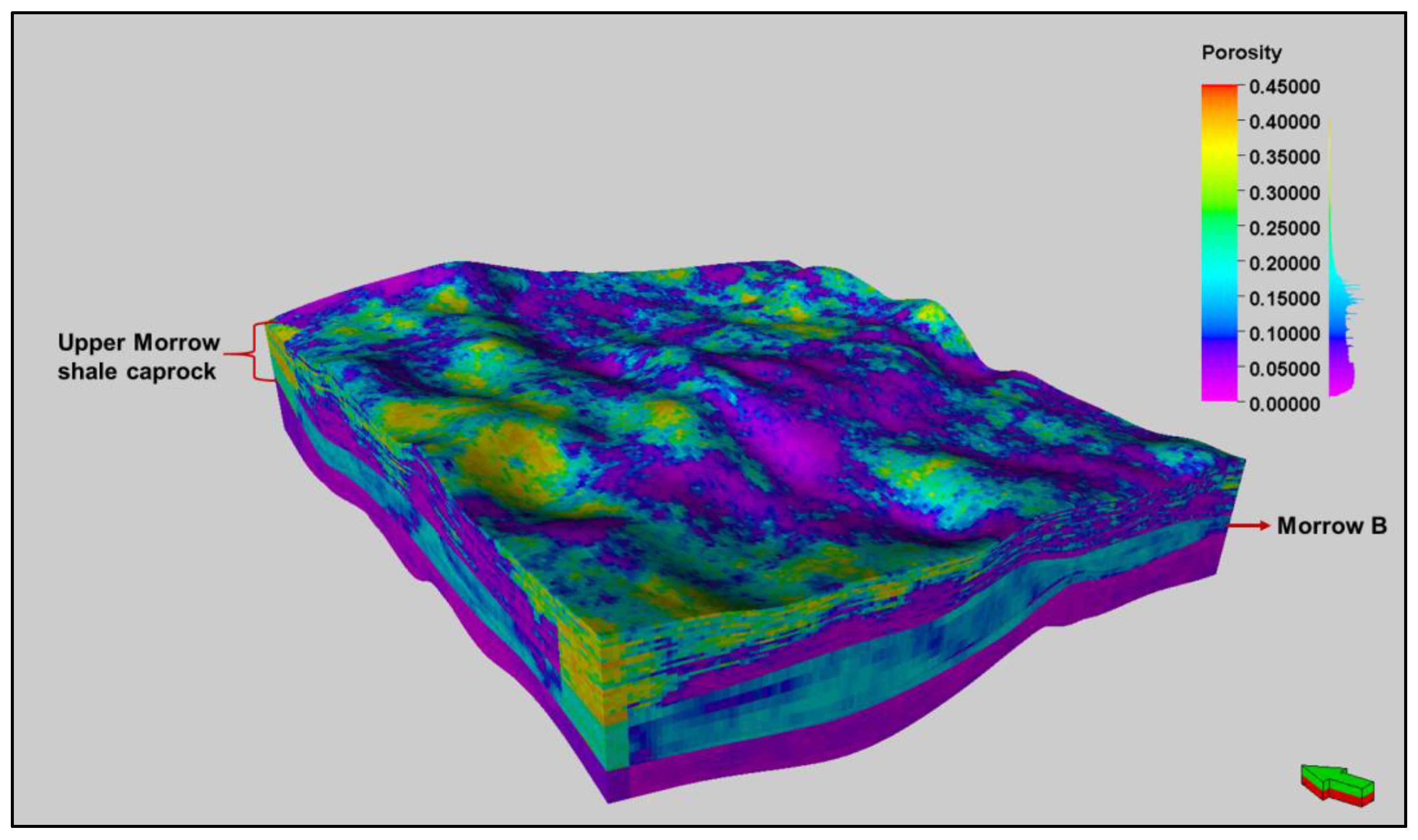
3.2. Geology of the Area

Extensive studies have been performed on the Morrow reservoirs since they are the primary targets for oil production [15,16,19,20,21]. The Morrow B formation is overlain by the Thirteen Finger limestone and Morrow shale which serve as excellent seals for the CO2 sequestered reservoir. Early researchers characterized the geology of the Morrow B formation by investigating and interpreting its depositional settings [17,22,23]. Preliminary studies classified the Morrowan sandstones as predominantly fluvial deposits with the overlying Thirteen Finger limestone consisting of estuarine to marginal marine deposits [17]. A general description of the stratigraphic sequence of the reservoir is provided by Gallagher [24] and Moodie et al. [25] as a series of rock units with coarse-grained conglomerates at the base, and fine estuarine sandstones lying on top. Figure 2 depicts a generalized sequence of lithofacies for the Morrow B formation composed of sediments of different depositional environments. Based on the lithofacies identified in rock cores from the Morrow B and B1 formation, the environmental conditions under which sedimentary rocks were formed were interpreted [17]. It is essential to consider the formation heterogeneity when assessing the potential for induced seismicity. The presence of micro-structures and minerals with different mechanical properties can influence the response of a rock to induced stresses and pore pressure changes. Heterogeneity can be assessed at multiple scales by examining the mineral grains, sediment type and the presence of geologic features, such as faults. The presence of varying lithofacies present in the Morrow B rock provides valuable information about the heterogeneity of the formation. A study performed by Gallagher [24] provided some preliminary insights into the heterogeneity within the Morrow B. The study examined the varying pore network and pore-to-throat ratios of the Morrow B formation. Further work performed by Ross-Coss [23] characterized the formation heterogeneity by defining eight hydrologic flow units based on the porosity–permeability relationships interpolated from core flooding experiments and petrographic studies.
Figure 3 presents the stratigraphic column of the FWU, highlighting the main production interval and different rock sections lying above and beneath the reservoir. A study performed by van Wijk et al. [26], using 3D seismic data and tracer experiments to understand the flow directions of the injected CO2, indicated that the impermeable caprock makes it less likely for injected CO2 to migrate vertically or flow southward. A defining characteristic of the FWU geology is that the injection zone (Morrow B) is not in direct contact with the Precambrian basement. The underlying Morrow shale reduces the likelihood for the triggering effect of CO2 WAG injection to be transferred to the basement rock. The existence of faults within sequestration reservoirs can potentially serve as migration pathways for injected CO2 to leak to surface. Additionally, faults within sedimentary strata-intersecting basement rocks can lead to the occurrence of high-magnitude seismic events when induced to slip. A study conducted by van Wijk et al. [26] found no direct evidence of faults in the reservoir or caprocks in the FWU.

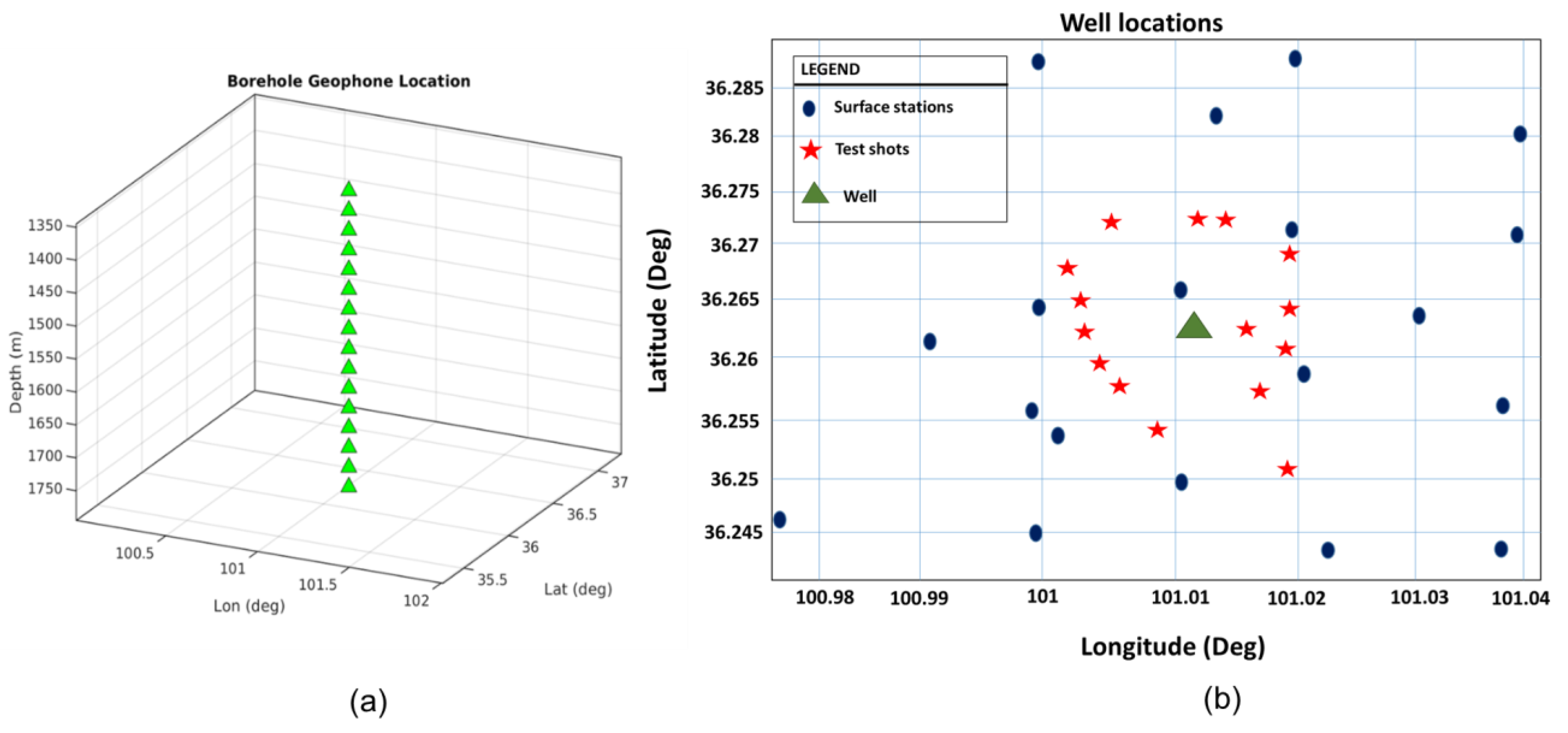
3.3. Acquisition of Field Data

In order to investigate the mechanism of induced seismicity in the FWU, multidisciplinary data were integrated in a simulation modeling effort to characterize the stress changes and model the microseismic occurrences. Time-lapse 3D VSP was utilized to monitor the impact of CO2-WAG injection on the FWU reservoir properties. A total of four 3D VSPs were taken, including a baseline survey and three monitor VSPs. A detailed description of the acquisition of the 3D VSPs is provided by Will et al. [21]. The processing of the VSP data to attenuate noise and subdue high-energy amplitudes was discussed by El-Kaseeh et al. [27]. Seismic velocities and depth-shift attributes were inverted from the 3D VSP. The seismic velocities at the monitor survey times (dVP) were computed relative to the baseline VSP survey. By computing the velocities, we can see how changes in fluid saturation affect the reservoir properties over time. Since the Morrow B formation is only about 24 feet thick, seismic velocities had to be focused on a smaller area to pick up on subtle changes within the reservoir. Seismic images were cropped outside a 1000 ft. radial distance from the monitoring well. Figure 4 illustrates the temporal evolution of the velocity distribution. The seismic velocities during the monitor survey VSP times (dVp) were estimated relative to the baseline VSP. The increasing velocity differences observed on Figure 4 demonstrate a preferential migration of the injected CO2 from the from the injector well (#13-10A) towards the producer well (13-6).

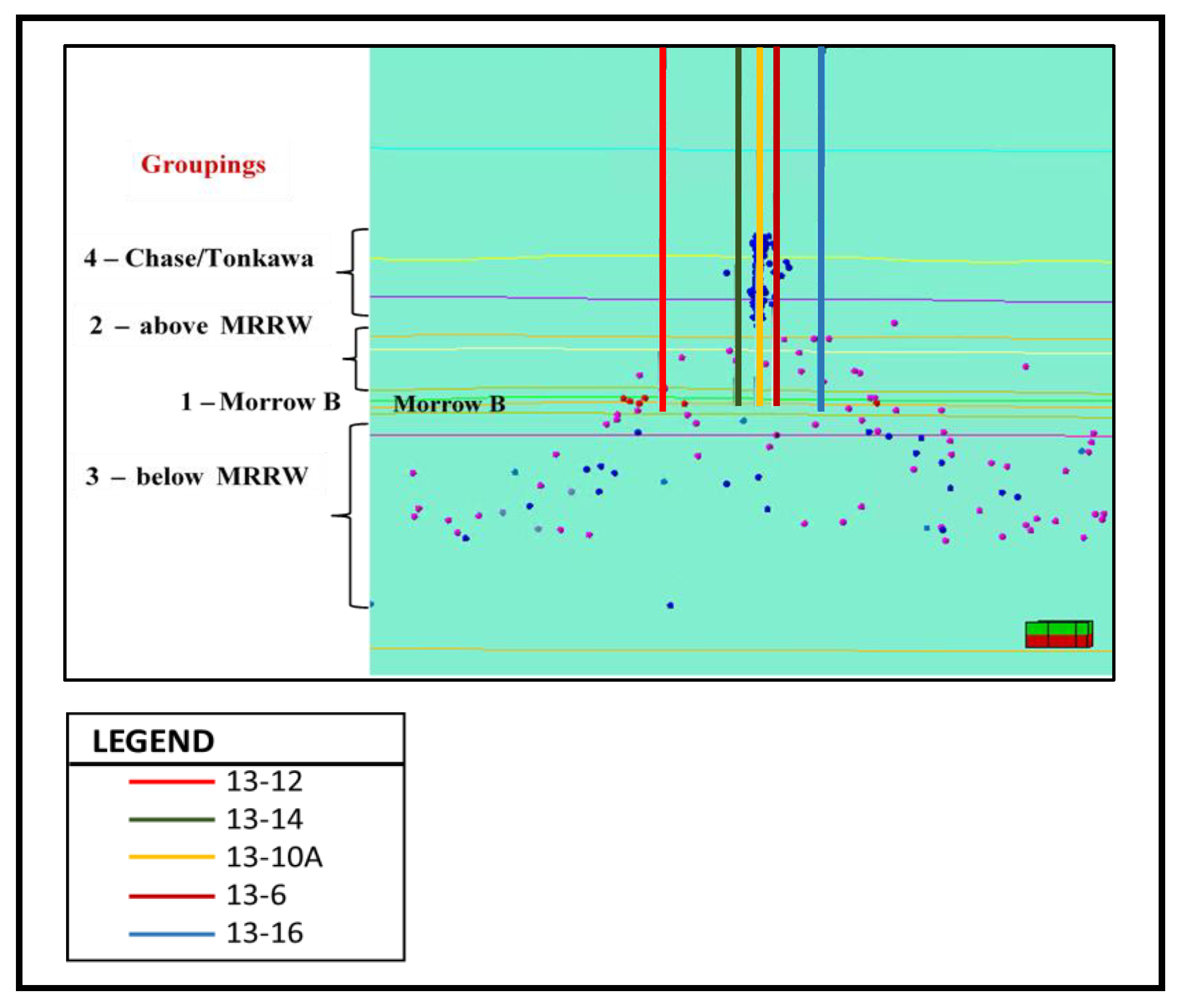
3.4. Microseismic Data

Microseismic events are observations of rock failure, providing valuable information about pore pressure changes and geomechanical behavior of oil and gas reservoirs. The progressive failure of a rock structure can be revealed by recording microseismic occurrences [28]. Microseismic monitoring was performed at the FWU site with both surface and wellbore receivers to improve the coverage and location of the seismic events. Sixteen-level, 3-component OYO seismometer arrays were deployed in a single vertical well. A detailed description of the deployment of the borehole and surface receivers are provided in Ampomah et al. [29]. Gao et al. [30] presented a novel adaptive full waveform approach to compute the moment tensor inversion for more complex source mechanisms. This method was applied to waveforms of the microseismic events.
Microseismic events were detected not only in the Morrow B formation but in rocks lying above and beneath the reservoir. Figure 5 shows the borehole geophones installed in a single vertical well and locations of the surface stations.

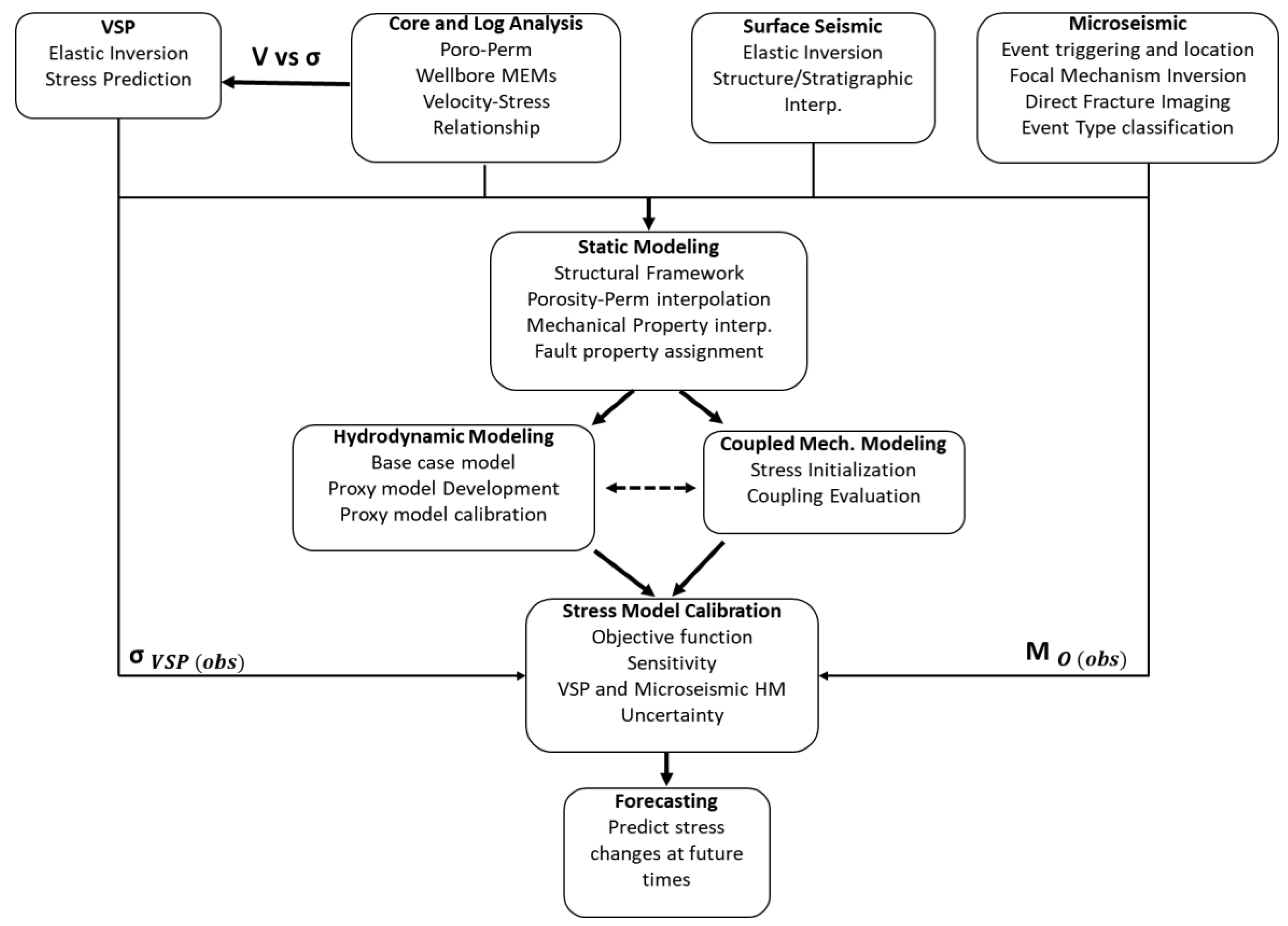
4. Materials and Methods

In order to predict the spatio-temporal stress variations and pore pressure distribution, a coupled mechanical-fluid flow model adopted from SWP research was integrated with multidisciplinary data. Data from cores, well logs and VSP were utilized to define the formation velocity variation due to stress changes. Other independent data, such as microseismic data, was integrated into the framework to improve the stress calibration and reduce the non-uniqueness of the simulation model. The dynamic reservoir model was calibrated for the primary and secondary recovery stages. However, this study focuses on the tertiary recovery period where time-lapse VSP acoustic measurements and microseismic data were obtained. Figure 6 illustrates a step-by-step framework employed to build and calibrate the coupled hydromechanical model. The calibration efforts were aided with the identification of uncertain model parameters. Among the uncertain parameters are the fracture properties (coefficient of friction, fault shear and normal Young’s modulus). Preexisting natural fractures within the Morrow B formation were treated as small-like faults to help with fault property assigning. This study is based on the fact that microseismic event locations are known and small-like faults are added at the event locations. Key fault properties are varied until plastic failure occurs. Modeling microseismic events requires estimating the stress drop. The stress drop tensor estimated from the model is averaged across the fault. The seismic moment magnitudes (Mw) are computed using the stress tensor and compared to observed Mw. After attaining a well calibrated stress model, it will be utilized to predict the stress/strain changes and potential microseismicity. This study utilizes microseismic events to constrain the stress field and provide a more accurate representation of the dynamic stress changes in the subsurface. The situation in the Farnsworth field suggests that even though the average bottomhole pressure (BHP) increased from 4000 psi (before August 2020) to 5500 psi (after August 2020), the potential for fluid injection to cause microseismicity in the subsurface did not result in the occurrence of several new microseismic events.

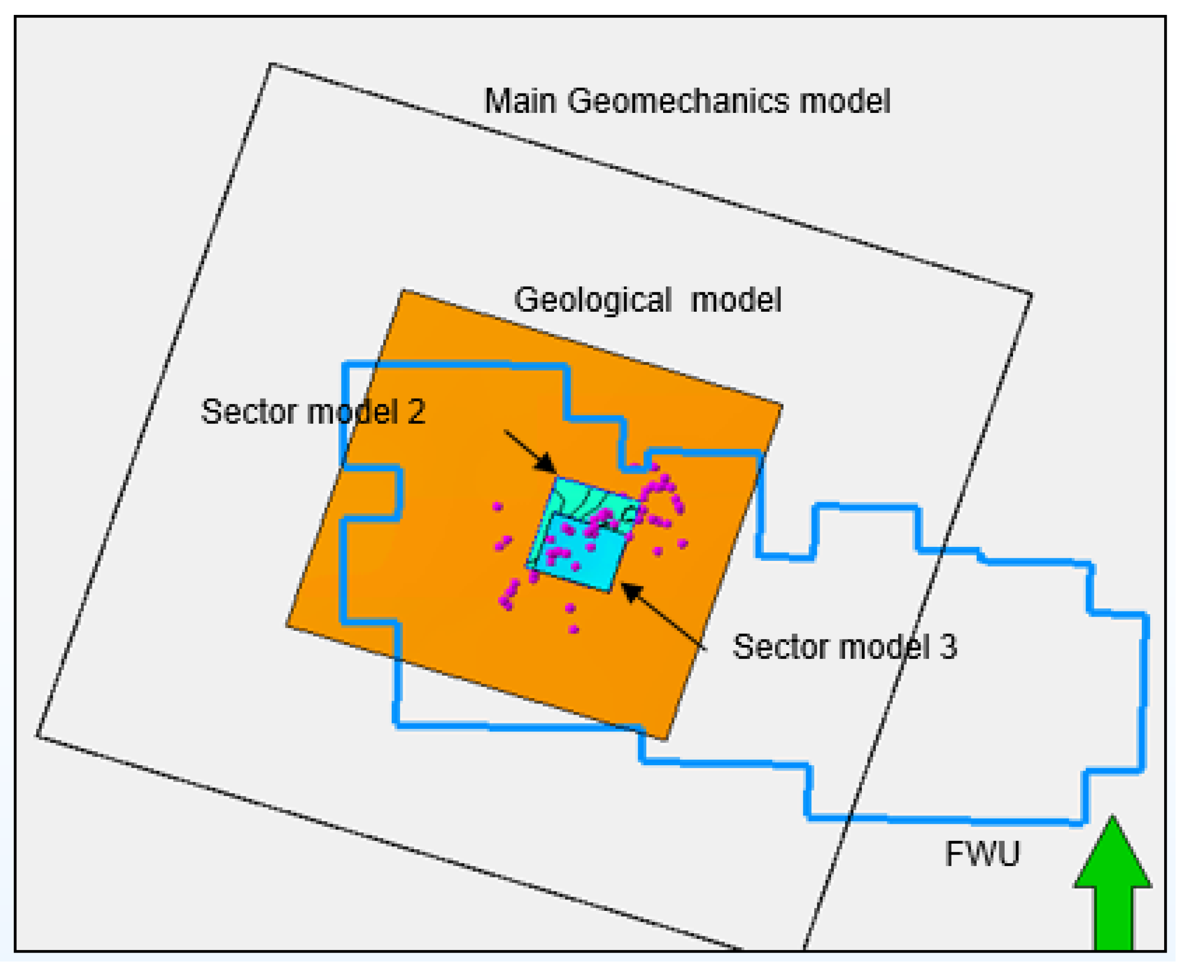
4.1. Numerical Simulation Model Setup

A numerical simulation model is essential for the proposed workflow. Modeling microseismic events within the Morrow B was based on utilizing a coupled hydromechanical model. All simulation works were performed on the West side of the FWU. A recent study by Ampomah et al. [31] presented the construction of the static reservoir geological model for the FWU, using geological, petrophysical, and field production data. Figure 7 shows a three-dimensional representation of the porosity distribution for the reservoir with the upper Morrow shale caprock formation. Several numerical simulation models for the Farnsworth Field Unit have been developed, taking into account the fluid-flow and geomechanical mechanisms that govern fluid transportation in the Morrow B. The numerical models were validated through extensive history matching using the field production and pressure data.
Figure 8 shows the boundaries for the reservoir geological model, main geomechanical model and the sector models. The geological model contains the structural framework of the formation with properties such as porosity and permeability associated with each cell. The main geomechanical model includes coarsened overburden, underburden and sideburden grid cells in addition to the 3D reservoir grid model. Sector models were derived from the primary geomechanical model in order to conduct detailed simulations in areas with microseismicity. The sector models utilized the main geomechanical model’s VSP-constrained stress as their boundary condition. Grid cells within the sector model were assigned the same thickness but varying dimensions in the I and J direction. Modeling the changes in subsurface stress requires hydrodynamically derived estimations of pore pressures. The reservoir simulator models the fluid flow in the FWU reservoir and computes the resulting pressures, saturation distributions and temperature. All of these works were performed in the Petrel environment. VISAGE [32], a finite element simulator, utilized the output from the reservoir simulator to model a 3D stress loading on the reservoir grid model and compute the rock stresses, deformations and failure. Table 1 shows the summary of the properties for each model utilized in the microseismic modeling.

4.2. Coupled Modeling

The 3D mechanical earth model was coupled with the reservoir simulation model to generate a dynamic geomechanical model. Even though two-way coupling appears rigorous, it is computationally costly and requires input such as porosity–stress and permeability–stress relationships. For this reason, a one-way coupling method was utilized. As an input, the geomechanical simulation model takes the derived pore pressure distributions from the reservoir simulation model at the baseline and the monitor survey times. The production of hydrocarbons is associated with a decrease in pore pressures and an increase in the effective stress. In contrast, formation pore pressures increase during fluid injection with little or minimal fluid withdrawal. The production history at the FWU is characterized by a gradual decline in reservoir pore pressure and an increase in the effective stress during the primary recovery stage. However, the implementation of waterflooding resulted in the opposite effect: an increase in the pore pressures and a decrease in effective stress. The tertiary recovery period is defined by fluctuating pore pressures as a result of the WAG injection, which influenced the effective stresses. This study modeled the effects of pore pressure fluctuations on the in situ stresses using the Biot effective stress coefficient, as expressed in Equation (1). The effective stress is defined as a function of the Biot coefficient, total stress and pore pressure Biot [33],
σ = σ α P p
where Pp represents pore pressure, psi; α is the Biot coefficient; σ is the effective stress; and σ is the total stress.
The Morrow B formation is heterogeneous and composed of quartz and clay minerals. For anisotropy materials, the Biot coefficient is expressed as,
α = 1 K d r y K s
where K s is the mineral bulk modulus, and K d r y is the dry bulk modulus.

4.2.1. Fracture Plane Failure Criteria

Mohr–Coulomb failure criteria was utilized to determine the plastic failure at the fracture surface. The Mohr–Coulomb failure criteria represents a set of linear equations that describes a failure envelope obtained from a plot of the shear strength of a material and the applied normal stress. The failure criterion is represented mathematically as [34],
τ = c + ( σ n P p ) t a n ( φ )
where τ is the shear stress, σ n is the normal stress, Pp is the pore pressure, and φ is the angle of internal friction. The cohesion and internal friction angle are relevant parameters in Mohr–Coulomb failure analysis, as they determine the shear strength of a rock under different stress conditions. The cohesion (c) and the internal friction angle determined for the Morrow B sandstone are 1746 psi and 40.77°, respectively.
By adjusting the normal and shear Young’s modulus, and the coefficient of friction, plastic failure occurs. Plastic failure is required to estimate the stress drop around the fault plane. The stress drop was evaluated as the differences in stresses for a coupled hydromechanical model without fault and a geomechanical model with fault added at microseismic event locations.

4.2.2. Microseismic Modeling

Microseismic events were simulated using a coupled hydromechanical model. Figure 9 shows the distinct categories of microseismic event occurrences. Group 1 events can be found in the Morrow B, where model calibration, well log data, and field measurements are all readily available. Events in Group 2 and Group 3 occurred above and beneath the reservoir, respectively. Modeling microseismic events below the Morrow B formation is challenging particularly due to the unavailability of well log data. This results in higher model uncertainty. Events classified under Group 4 result from a separate failure mode, which falls outside the scope of this study. Several microseismic events were identified and their moment tensors computed by fitting a waveform to the recorded data [30]. Only moment tensors with a good waveform fit were selected; hence, not all events had moment tensor solutions. There were 32 tensor events and 136 magnitude events in the event collection. Tensor events had moment magnitude and sufficient quality (SNR), such that, stress drop tensor and fault plane orientation information could be determined.

4.2.3. Computation of Moment Magnitudes

Stress drops for the plastic cells were transformed into microseismic parameters (moment tensors and magnitudes) using a coupled hydro-geomechanical model. Moment tensor computation led to estimates of the seismic energy and moment magnitudes. Moment tensors describe the nature of forces acting at a seismic source that generates seismic waves. Moment tensors are useful for determining the focal mechanism of a seismic event. Mathematically, moment tensors can be expressed in terms of their eigenvalues (type of slip at seismic source) and eigenvectors (orientation of the slip). Each moment tensor can be decomposed into three constituents: an isotropic compression (IC) component, a compensated linear vector dipole (CLVD), and a double couple (DC). Stress drops ( σ i k ) and the displacement vector (r) are used to derive the seismic moment tensors, M i k
M i k = V σ i k r · d 3 r μ V γ i k r ¯ · d 3 r
Alternatively, the moment tensor can be computed using a finite element model and focusing on elements that have undergone plastic deformation. As each element with linear interpolation functions has stress data at a single point, Equation (8) simplifies as,
M i k = σ V
Beginning with the plastic cells, the stress drop tensors ( Δ σ i k ) are computed. The volume of interest (V) is estimated using the cells that have undergone plastic failure. Although the volume of interest is estimated from the numerical simulation model, it can be assigned as an uncertain. The strain energy which characterizes the energy released from rock deformation can be expressed as,
M O = 1 2 i = 1 3 λ i 2 1 / 2
The seismic energy is determined as,
E s = M O × 1.6 × 10 5
The moment magnitude ( M w ) , expressed in dyne cm is computed as,
M w = 2 3 L o g M O 16.1 ,
where λ 1 to λ 3 are the eigenvectors of the moment tensor.
The above procedure was implemented in a python script to compute seismic energy and moment magnitudes utilizing cells that have undergone plastic deformation.

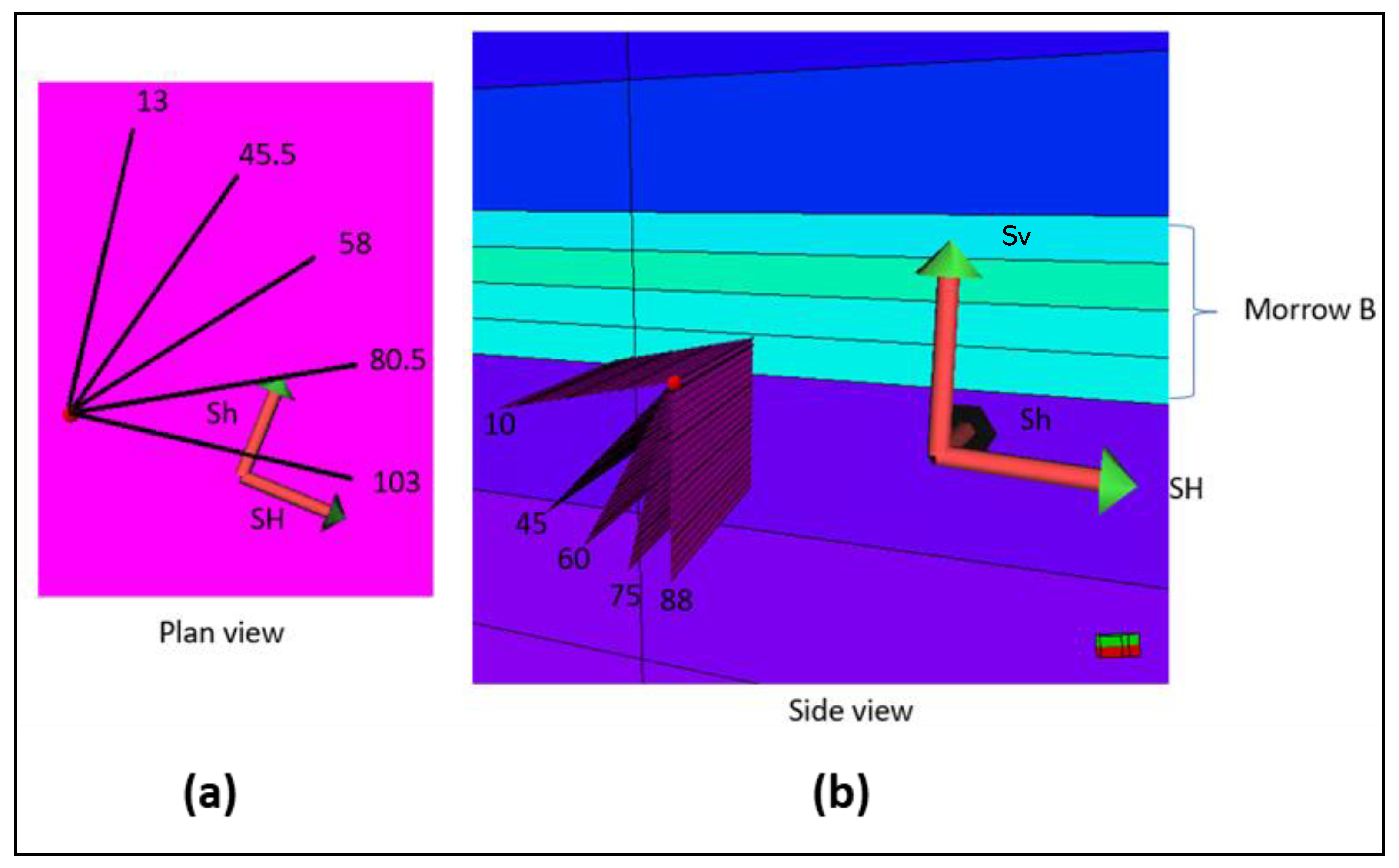
4.2.4. Fracture Parameterization

Fracture property parameterization permits the modeler to explore multiple fracture orientation scenarios and determine the optimal combination of parameters for simulating plastic failure in the rock formation. Variations in fracture parameters including fracture strike, dip, coefficient of friction, normal and shear Young’s modulus were simulated, and their impact to cause failure at the fault locations were evaluated. Table 2 summarizes the relative impact of the parameters on plastic failure. Figure 10 shows the range of values assumed for the fracture strike and dip.

5. Simulation Results

This section presents the simulation results for utilizing a coupled hydromechanical model to predict the injection induced seismicity. Moment magnitudes computed using the finite element simulator are compared to the magnitudes derived from the field microseismic data. The primary contributing factor to the occurrence of microseismic events within the Farnsworth Field Unit is unknown, despite the long history of waterflooding followed by CO2 water-alternating-gas injection. The detection of microseismic events has been attributed to the reactivation of unknown fractures or aseismic geologic features within the formation. The results of a study are shown to identify the existence of a direct correlation of formation pore pressure changes and microseismic event occurrences. The analyses of a sensitivity study performed to determine the critical parameters and their impact on fault reactivation is demonstrated.

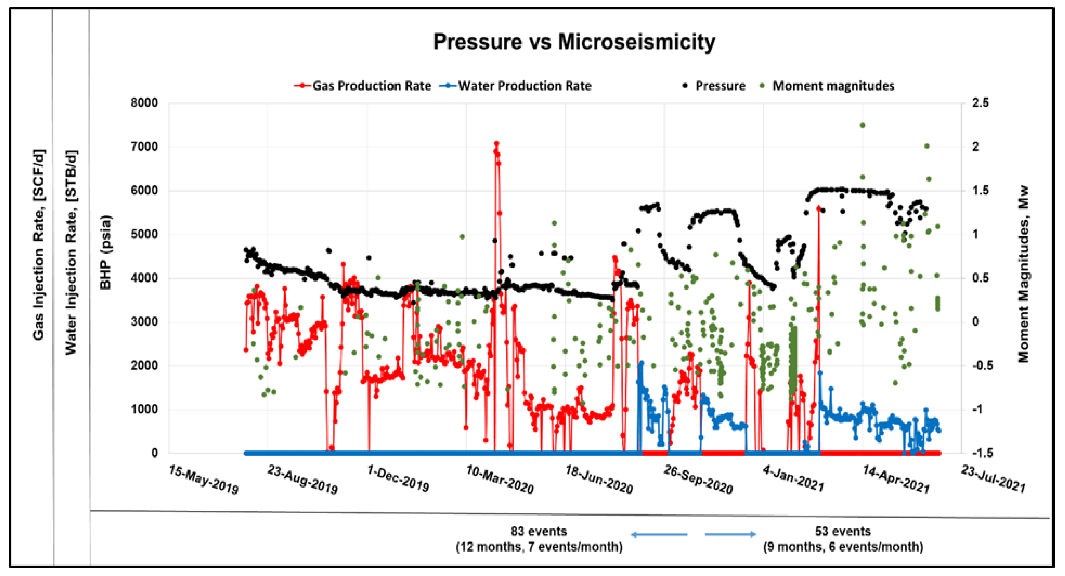
5.1. Effects of Injection Rates, Bottomhole Pressure on Microseismic Occurrences

Figure 11 shows a plot of the gas and water injection rates. The accompanying bottomhole pressures and microseismic detections are plotted for the same time period (July 2020–April 2021). The figure revealed that high bottomhole pressures are recorded during water injection periods and lower bottomhole pressures during gas injection. It can be seen from the plot that the microearthquakes detections are not directly correlated to the bottomhole pressure fluctuations. An increase in bottomhole pressure is not translated directly to high incidence of microearthquakes. The high spike in microearthquake detections is from shallow depths, shown by the large CLVD component, which indicates a tensile cracking.
Figure 12 shows an extended plot of microseismic occurrences, bottomhole pressures, and the rate of water and gas injection from August 2019 to June 2021. Microseismic events are represented as magnitudes (green dots) with the water injection rate shown as a solid blue line, gas injection rate (as a solid red line) and the bottomhole pressures (as black dots). A total of 136 microseismic events were analyzed for the time period. The magnitude of events ranges between −1.5 and +1.2 with the majority falling between −1.1 and 0. These occurrences are of small magnitudes and are therefore not felt at surface. The tertiary CO2 WAG period shown in Figure 10 indicates water injectivity issues, as high bottomhole pressures are recorded during the water injection rather than CO2 injection. Field operators tend to inject water at high bottomhole pressures to build the reservoir pressure and increase oil recovery. Although this practice could lead to some recovered oil, there is a high likelihood of fractures being created. Injected water would preferentially travel through the fractures and channels created, leaving the oil behind.
In August 2020, there was an increase in bottomhole pressure (BHP). While the ratio of microearthquake occurrences per month did not increase much (from seven events per month to six events per month), the events were spatially dispersed. Figure 13 shows the microseismic events around the 13-10A injection pattern. Prior to August 2020, microseismic occurrences clustered close to the wells, but as the pressure increased, the events occurred further from the wells as shown in Figure 14.

5.2. Main Geomechanics and Sector Model Calibration

Calibrating geomechanical models with a 1D mechanical earth model (MEM) ensures that the predictions from the geomechanical simulations are in conformity with the prevailing in situ stresses. The properties of the generated FWU geomechanical model were adjusted to produce a good agreement with the 1D MEM calibration at the wellbore. Figure 15 shows a comparison of 1D properties with 3D properties for the main geomechanics model. Elastic properties (Young’s modulus, Poisson’s ratio and Bulk density) are indicated in the first three tracks, respectively. The overburden stress is shown in track four. The maximum horizontal stress, minimum horizontal and vertical stress at 1955 are in tracks four through six, and shown again in tracks seven to nine at 2014. The good agreement between the 1D MEM and the geomechanical model is seen within and around the Morrow B formation.
Sector models were created to examine detail stress changes for time lapse VSP stress constraint and microseismic event modeling. However, it was important to ensure the same stress loading for the main geomechanical model is applied for the sector model. To verify that the loading has not changed, a comparison is made between the main geomechanical model and the sector model. A good agreement for the stress loading is observed between the sector model and the main geomechanical model, as shown in Figure 16. After a successful calibration, the coupled geomechanical model is utilized to examine the stress changes and/or failure over time. The objective function for the time-lapse VSP and modeled velocity from stress change is formulated by running the sector model in the elastic region. For the microseismic event, plastic failure is required to identify the plastic cells and stress drop in cells around the fractures with microseismicity occurring.

5.3. Events within Morrow B Sandstone

As mentioned previously, microseismic events were separated into four groups and for the purpose of this study; events occurring in the Morrow B will be the main focus. Figure 17 shows a plan view of the stress drop caused by the interaction of pore pressure variations with the rock mechanical properties. The amount of stress released is measured by the stress drop following an occurrence. The stress drops are closely related to the microseismic occurrence and reflects the magnitude of the microseismic event and the potential for future seismic activity. An event with a larger stress drop will have higher moment magnitudes.
Two events were identified within the Morrow B formation with Event 1 occurring on 31 January 2020 and Event 2 occurring on 2 March 2020.

5.4. Sensitivity Study on Fault Properties

A sensitivity analysis was conducted to determine the impact of uncertain fault properties on fault reactivation and associated seismicity during the historical period of CO2-WAG injection. The parameter ranges of the fault strikes and dips, coefficient of friction, normal and shear Young’s modulus were explored using the one variable at a time (OVAT) method. We determined that the normal and shear Young’s modulus had a smaller impact on the results for the parameter ranges examined. Nevertheless, the study revealed that the friction coefficient (µ) was the most sensitive parameter with inelastic failure occurring with lower (µ). Table 2 summarizes the parameter ranges and their relative impact on fault failure.

5.5. Moment Magnitudes Computation Results

Beginning with Scenario 1, faults are introduced at the locations of microseismic events and essential fault parameters are varied until inelastic failure occurs. Figure 18 shows the plastic cells surrounding a fault plane. The graph on the bottom shows the simulated pressures and total stress for a single plastic cell over time. Only the plastic failure cells are utilized to calculate the stress drop around the fracture plane. The stress drop for each plastic cell is computed as the differential between the total stresses derived from a coupled mechanical model with no fault and a model with fault addition. Modeling the precise timing of event failure is outside the scope of this work; however, we have leading knowledge of when the event happened and the stress prior to the event time. The statistics of the stress drop for a coupled hydromechanical case with a coefficient of friction (0.53), strike (322.25°) and dip (78.99°) is shown in Table 3.
The mean stress drops together with the volume of interest were utilized to generate the moment tensors. The unit of the moment tensor is dyne cm. The stress drops were converted from psi to dyne/cm2. The volume of interest (V) was estimated in cm3. Utilizing the Python script, the moment magnitudes of the seismic event (event df22) is computed below, as shown in Figure 19.
For each microseismic event, Mw was determined for each potential fracture orientations using the equations outlined under moment magnitudes computation. Table 4 displays the simulated Mw and associated parameters. Just above the Morrow B sand, in the Morrow shale, is where Event 1 can be found. Event 2 is located in the Morrow B.
Starting with Event 2 (located within the Morrow B sand), we find that the most probable orientation is the one with a 322° strike and 79° dip. With a coefficient of friction of 0.53 (friction angle of 28°), plastic failure develops. However, the orientation of a 79° strike and 24° dip has a very modest failure even at 0.36 coefficient of friction, which indicates that it is more difficult for failure to occur in this stress orientation when the dip is closer to horizontal. This is congruent with findings from the section on fracture property parameterization. Each of the two probable orientations for Event 1 has a 66° dip. Both orientations are viable. The moment magnitude for both modeled events falls within the same magnitude range, as the observed Mw and the magnitude of Event 1 is less than that of Event 2, which corresponds to the observed values.

6. Discussion

In the study of induced seismicity, especially in the setting of fluid injection/production, the use of coupled hydrogeomechanical modeling approaches has become more and more prominent. The outcomes of our modeling approach for examining the mechanisms underlying induced seismicity are discussed in this section, along with any potential ramifications regarding subsurface seismic hazard mitigation. Our modeling framework was based on a coupled hydromechanical approach that utilizes pore pressure estimates from the reservoir simulation model to simulate the spatiotemporal evolution of induced seismicity. The numerical simulations were conducted for a five-spot injection pattern in the Morrow B formation. Numerical simulations were performed in the Petrel environment, where the Eclipse E300 computes the pressure and saturation distribution for each timestep and a finite element simulator (VISAGE), and models the complex changing stress field. We showed how the method of inelastic failure was utilized to understand and model microseismic event occurrences. The outcomes of the geomechanical modeling were presented against observations of induced seismicity.

6.1. Stratigraphy

The stratigraphy of a formation can influence the likelihood of small seismic events occurring. Injecting into formations with close proximity to the crystalline base rock has resulted in the occurrence of high magnitude earthquakes. The crystalline basement is a dense and fractured formation that often underlies the sedimentary formation. The crystalline basement acts as a barrier to fluid flow. The presence of faults intersecting the sedimentary strata and the close proximity of the injection formation and basement rock are two key factors that induces deep matured fault structures to slip [11]. This was found to be the primary contributing factor to the occurrence of high magnitude earthquakes in West Texas Delaware basin and Oklahoma. At the FWU, all wells inject into the Morrow B formation that is overlain and underlain by excellent seal rocks. Additionally, there are no identified faults intersecting the producing formation and the crystalline basement.

6.2. Fluid Injection

Wastewater injection has been associated with increased microseismic activities [35]. In waste disposal, produced water from oil and gas operations is injected into deep underground formation. The success of the underground disposal is dependent on the integrity of the geologic formation to safely contain the injected fluids to avoid contamination with underground water sources. Wastewater injection is different from oil and gas production with the former involving fluid injection without withdrawal. The result is a buildup of pore pressures that cause the subsurface rock to reach a critical stress state, causing the formation to rupture, generate small seismic events or trigger larger earthquakes. The situation observed in the FWU involves the simultaneous production of hydrocarbons and the injection of fluids. Pore pressure increases from fluid injection can be potentially balanced with hydrocarbon production. Although no direct correlation was found between fluid injection and occurrence of seismic events in the FWU, pore pressure changes could be a primary contributing factor to induced seismicity, as they altered the effective stresses in the rock mass, inducing failure in the intact formation or along optimally oriented planes of weakness.

6.3. Analysis on Microseismic Modeling

Microseismic events are indications of subsurface stress changes and typically have magnitudes less than 2.0 on the Richter scale. Although low magnitude seismic events are not felt on surface, they are important indicators of rock behavior and can provide valuable information about the progressive failure of a rock mass, due to hydrocarbon production or fluid injection. The method of using inelastic failure to model the process of rocks deforming and ultimately failing under stress showed to be successful in this study. The magnitudes of events modeled in this study were small (Mw < 2), and not large enough to raise safety concerns. While magnitudes may be small, the location and number of events play significant roles in determining safety. Microseismic events were seen to spread out from the injection/production wells with pressure increase. The low magnitude earthquakes occurred at lower rates with pore pressure variation. Overall, the results of our study demonstrate the effectiveness of geomechanical modeling as a tool for investigating induced seismicity.

7. Conclusions

Microseismic events were successfully modeled within the Morrow B by incorporating faults into the coupled hydromechanical model and running the simulation model for regions with plastic failure. The following findings resulted from the effective application of multidisciplinary data (time-lapse VSP seismic data and microseismic data) to characterize the dynamic stress field associated with the ongoing CO2-EOR operation. The results of analysis are as follows:
  • A manual framework for integrating multidisciplinary data to improve stress prediction of the Morrow B using VSP and microseismic data were developed. The mechanical earth model was initially calibrated using the VSP data, which carries the combined effect of fluid substitution and stress changes on the seismic velocities. Integration of microseismic data allowed for further constraint of the model. To assess the impact of key model parameters on the stress calibration, the integration framework can be automated and several simulation cases could be run.
  • Having prior knowledge of the microseismic event locations and adding fractures at these locations were useful in the geomechanical stress modeling and prediction. This procedure required the reservoir engineer to specify fault locations within the geomechanical model before running for failure. Moment magnitudes computed were within the same magnitude for events in the Morrow B, suggesting the suitability of this approach. Nonetheless, the coupled hydro-geomechanical model could be run for plastic failure and regions of deformations are identified and compared to the known microseismic event locations.
  • The magnitudes of the microseismic events observed in the FWU are not large enough to cause safety concerns. The absence of active faults within the Morrow B and the presence of an underlying Morrow shale could be a major contributing factor to the occurrence of low magnitudes microseismic events.

Author Contributions

Conceptualization, W.A. and D.L.; Formal analysis, S.A.A., W.A., D.L. and A.E.-A.; Funding acquisition, W.A.; Investigation, S.A.A., W.A. and D.L.; Methodology, W.A. and D.L.; Project administration, W.A. and D.L.; Resources, W.A.; Software, W.A.; Supervision, W.A. and D.L.; Validation, W.A. and D.L.; Visualization, S.A.A., W.A., D.L. and A.E.-A.; Writing—original draft, S.A.A. and D.L.; Writing—review and editing, S.A.A., D.L. and A.E.-A. All authors have read and agreed to the published version of the manuscript.

Funding

Funding for this project is provided by the U.S. Department of Energy’s (DOE) National Energy Technology Laboratory (NETL) through the Southwest Regional Partnership on Carbon Sequestration (SWP) under Award No. DE-FC26-05NT42591. Additional support through the stress project sponsored by NETL under award number DE-FE0031684.

Data Availability Statement

The three dimensional surface seismic dataset, Vertical Seismic Profile (VSP) and Microseismic data acquired from the FWU field were provided by the Southwest Regional Partnership on Carbon Sequestration (SWP). The historical production and injection dataset utilized in this study were provided by the Field operator, Perdure Petroleum, LLC.

Conflicts of Interest

The authors declare no conflict of interest.

References

  1. Intergovernmental Panel on Climate Change. Climate Change 2022—Mitigation of Climate Change; Full Report; IPCC: Geneva, Switzerland, 2022. [Google Scholar]
  2. Bradshaw, J.; Zhenlin, C.; Amit, G.; Dario, G.; Rogner, H.; Simbeck, D.; Williams, R. Sources of CO2—Intergovernmental Panel on Climate Change; World Meteorological Organization: Geneva, Switzerland, 2019. [Google Scholar] [CrossRef]
  3. Beck, L. The US Section 45Q Tax Credit for Carbon Oxide Sequestration: An Update; Global CCS Institute: Melbourne, Australia, 2020. [Google Scholar]
  4. Nagabhushan, D.; Russell, R.; Waltzer, K.; Thompson, J.; Beck, L.; Jaruzel, M. Carbon capture: Prospects and policy agenda for CO2-neutral power generation. Electr. J. 2021, 34, 106997. [Google Scholar] [CrossRef]
  5. Ampomah, W.; Balch, R.S.; Grigg, R.B.; McPherson, B.; Will, R.; Lee, S.Y.; Dai, Z.; Pan, F. Co-optimization of CO2-EOR and storage processes in mature oil reservoirs. Greenh. Gases Sci. Technol. 2017, 7, 128–142. [Google Scholar] [CrossRef]
  6. Jenkins, C.R.; Cook, P.J.; Ennis-King, J.; Undershultz, J.; Boreham, C.; Dance, T.; de Caritat, P.; Etheridge, D.M.; Freifeld, B.M.; Hortle, A.; et al. Safe storage and effective monitoring of CO2 in depleted gas fields. Proc. Natl. Acad. Sci. USA 2012, 109, E35–E41. [Google Scholar] [CrossRef] [PubMed]
  7. NETL (National Energy Technology Laboratory). Site Screening, Site Selection, and Site Characterisation for Geological Storage Projects. Best Practices. 2017. Available online: https://netl.doe.gov/sites/default/files/2018-10/BPM-SiteScreening.pdf (accessed on 28 March 2023).
  8. McClure, M.W.; Horne, R.N. Correlations between formation properties and induced seismicity during high pressure injection into granitic rock. Eng. Geol. 2014, 175, 74–80. [Google Scholar] [CrossRef]
  9. Tutuncu, A.N.; Bui, B.T. A coupled geomechanics and fluid flow model for induced seismicity prediction in oil and gas operations and geothermal applications. J. Nat. Gas Sci. Eng. 2016, 29, 110–124. [Google Scholar] [CrossRef]
  10. Skoumal, R.J.; Kaven, J.O.; Barbour, A.J.; Wicks, C.; Brudzinski, M.R.; Cochran, E.S.; Rubinstein, J.L. The induced MW 5.0 March 2020 West Texas seismic sequence. J. Geophys. Res. Solid Earth 2021, 126, e2020JB020693. [Google Scholar] [CrossRef]
  11. Pei, S.; Peng, Z.; Chen, X. Locations of Injection-Induced Earthquakes in Oklahoma Controlled by Crustal Structures. J. Geophys. Res. Solid Earth 2018, 123. [Google Scholar] [CrossRef]
  12. Zoback, M.D.; Lund Snee, J.E. Predicted and observed shear on preexisting faults during hydraulic fracture stimulation. In SEG Technical Program Expanded Abstracts; Society of Exploration Geophysicists: Houston, TX, USA, 2018; pp. 3588–3592. [Google Scholar] [CrossRef]
  13. McMillan, M.D. Stepwise Dynamic Calibration of a Hydromechanical Simulation Using Time-Lapse Vertical Seismic Profile. In ProQuest Dissertations and Theses; New Mexico Institute of Mining and Technology PP: Socorro, NM, USA, 2021. [Google Scholar]
  14. Chen, R.; Xue, X.; Park, J.; Datta-Gupta, A.; King, M.J. New insights into the mechanisms of seismicity in the Azle area, North Texas. Geophysics 2020, 85, EN1. [Google Scholar] [CrossRef]
  15. Adu-Gyamfi, B.; Ampomah, W.; Tu, J.; Sun, Q.; Erzuah, S.; Acheampong, S. Assessment of chemo-mechanical impacts of CO2 sequestration on the caprock formation in Farnsworth oil field, Texas. Sci. Rep. 2022, 12, 13023. [Google Scholar] [CrossRef]
  16. Acheampong, S.A.; Ampomah, W.; Khaniani, H.; Will, R.; Sarkodie-Kyeremeh, J. Quantitative interpretation of time-lapse seismic data at Farnsworth field unit: Rock physics modeling, and calibration of simulated time-lapse velocity responses. Greenh. Gases Sci. Technol. 2022, 12, 671–697. [Google Scholar] [CrossRef]
  17. Cather, M.; Rose-Coss, D.; Gallagher, S.; Trujillo, N.; Cather, S.; Hollingworth, R.S.; Mozley, P.; Leary, R.J. Deposition, diagenesis, and sequence stratigraphy of the Pennsylvanian Morrowan and Atokan intervals at Farnsworth Unit. Energies 2021, 14, 1057. [Google Scholar] [CrossRef]
  18. Xiao, T.; McPherson, B.; Esser, R.; Jia, W.; Dai, Z.; Chu, S.; Pan, F.; Viswanathan, H. Chemical Impacts of Potential CO2 and Brine Leakage on Groundwater Quality with Quantitative Risk Assessment: A Case Study of the Farnsworth Unit. Energies 2020, 13, 6574. [Google Scholar] [CrossRef]
  19. Asante, J.; Ampomah, W.; Rose-Coss, D.; Cather, M.; Balch, R. Probabilistic assessment and uncertainty analysis of CO2 storage capacity of the Morrow B Sandstone—Farnsworth field unit. Energies 2021, 14, 7765. [Google Scholar] [CrossRef]
  20. Rasmussen, L.; Fan, T.; Rinehart, A.; Luhmann, A.; Ampomah, W.; Dewers, T.; Heath, J.; Cather, M.; Grigg, R. Carbon storage and enhanced oil recovery in Pennsylvanian Morrow Formation clastic reservoirs: Controls on oil–brine and oil–CO2 relative permeability from diagenetic heterogeneity and evolving wettability. Energies 2019, 12, 3663. [Google Scholar] [CrossRef]
  21. Will, R.; Bratton, T.; Ampomah, W.; Acheampong, S.; Cather, M.; Balch, R. Time-Lapse Integration at FWU: Fluids, Rock Physics, Numerical Model Integration, and Field Data Comparison. Energies 2021, 14, 5476. [Google Scholar] [CrossRef]
  22. Munson, T.W. Depositional, Diagenetic, and Production History of the upper Morrowan Buckhaults Sandstone, Farnsworth Field Ochiltree County Texas; Datapages, Inc.: Tulsa, OK, USA, 1989; pp. 1–20. [Google Scholar]
  23. Ross-Coss, D.; Ampomah, W.; Cather, M.; Balch, R.; Mozley, P.; Rasmussen, L. An Improved Approach for Sandstone Reservoir Characterization. In Proceedings of the SPE Western Regional Meeting, Anchorage, AK, USA, 23–26 May 2016. [Google Scholar] [CrossRef]
  24. Gallagher, S. Depositional and Diagenetic Controls on Reservoir Heterogeneity: Upper Morrow Sandstone, Farnsworth Unit, Ochiltree County, Texas. Ph.D. Thesis, New Mexico Institute of Mining and Technology, Socorro, NM, USA, 2014. [Google Scholar]
  25. Moodie, N.; Ampomah, W.; Jia, W.; McPherson, B. Relative Permeability: A Critical Parameter in Numerical Simulations of Multiphase Flow in Porous Media. Energies 2021, 14, 2370. [Google Scholar] [CrossRef]
  26. van Wijk, J.; Hobbs, N.; Rose, P.; Mella, M.; Axen, G.; Gragg, E. Analysis of geologic CO2 migration pathways in Farnsworth Field, NW Anadarko Basin. Energies 2021, 14, 7818. [Google Scholar] [CrossRef]
  27. El-Kaseeh, G.; Czoski, P.; Will, R.; Balch, R.; Ampomah, W.; Li, X. Time-lapse vertical seismic profile for CO2 monitoring in carbon capture, utilization and sequestration/EOR, Farnsworth project. In Proceedings of the 2018 SEG International Exposition and Annual Meeting, SEG 2018, Anaheim, CA, USA, 14–19 October 2018; pp. 5377–5381. [Google Scholar] [CrossRef]
  28. Ma, T.; Lin, D.; Tang, C.; Yadav, K.P.; Feng, Z.; Ma, K. Microseismic Monitoring, Positioning Principle, and Sensor Layout Strategy of Rock Mass Engineering. Geofluids 2020, 2020, 8810391. [Google Scholar] [CrossRef]
  29. Ampomah, W.; Will, R.; Mcmillan, M.; Bratton, T.; Huang, L.; El-kaseeh, G.; Liu, X.; Li, J.; Lee, D. Improving Subsurface Stress Characterization for Carbon Dioxide Storage Projects. In Proceedings of the 15th Greenhouse Gas Control Technologies Conference, Abu Dhabi, United Arab Emirates, 15–18 March 2021; pp. 15–18. [Google Scholar]
  30. Gao, K.; Huang, L.; Qin, Y.; Chen, T.; Coblentz, D.; El-kaseeh, G.; Bratton, T. Adaptive full-waveform moment-tensor inversion of microseismic data. In Proceedings of the SEG/AAPG/SEPM First International Meeting for Applied Geoscience & Energy, Denver, CO, USA and online, 26 September–1 October 2021. [Google Scholar] [CrossRef]
  31. Ampomah, W.; Balch, R.S.; Ross-Coss, D.; Hutton, A.; Cather, M.; Will, R.A. An Integrated Approach for Characterizing a Sandstone Reservoir in the Anadarko Basin. Paper presented at the Offshore Technology Conference, Houston, TX, USA, 2–5 May 2016. [Google Scholar] [CrossRef]
  32. Schlumberger. VISAGE Reference Manual—Schlumberger Private; Schlumberger: Houston, TX, USA, 2018. [Google Scholar]
  33. Biot, M.A. General Theory of Three-Dimensional Consolidation. J. Appl. Phys. 1941, 12, 155–164. [Google Scholar] [CrossRef]
  34. Karimnezhad, M.; Jalalifar, H.; Kamari, M. Investigation of caprock integrity for CO2 sequestration in an oil reservoir using a numerical method. J. Nat. Gas Sci. Eng. 2014, 21, 1127–1137. [Google Scholar] [CrossRef]
  35. Kozlowska, M.; Brudzinski, M.; Friberg, P.; Skoumal, R.; Baxter, N.; Currie, B. Maturity of nearby faults influences seismic hazard from hydraulic fracturing. Proc. Natl. Acad. Sci. USA 2018, 115, 201715284. [Google Scholar] [CrossRef] [PubMed]
Figure 1. (a) Location of the Farnsworth Unit (FWU) in the Anadarko basin. (b) Detailed map showing anthropogenic CO2 sources and utilization and storage sites.
Energies 16 04163 g001
Figure 2. Lithofacies from different depositional environments identified within the Morrow B formation. Figure modified from (Cather et al. [18]).
Energies 16 04163 g002
Figure 3. Stratigraphic sequence of different rock units at the Farnsworth Field area with the corresponding Gamma ray log from well 13-10A. Depths measured from the mean sea level. The different colors denote the different rock formations in FWU. (Figure modified from van Wijk et al. [26]).
Energies 16 04163 g003
Figure 4. Depth slice of the compressional velocity distribution for each baseline-monitor pairs. Images acquired below the reservoir interval. Figure shows the velocities for the monitor 1—base (a), monitor 2—base (b), and monitor 3—base (c).
Energies 16 04163 g004
Figure 5. (a) Diagram depicting the borehole geophones in a single vertical well and (b) location of the monitoring well and surface stations. The blue dots represent the surface stations. The red stars denote the locations for the test shots.
Energies 16 04163 g005
Figure 6. Schematic of the stress calibration workflow.
Energies 16 04163 g006
Figure 7. 3D view of the porosity distribution showing the Morrow B sandstone beneath the caprock formation.
Energies 16 04163 g007
Figure 8. A 2D areal view of the models considered in modeling the microseismic events. Boundaries of the reservoir geological model, geomechanical model and sector models are shown.
Energies 16 04163 g008
Figure 9. Cross-sectional view of the geologic formations in FWU, showing microseismic events in the overlying formation within the Morrow B and underlying formation. The vertical straight lines represent wells within the 13-10A injection pattern. The pink and blue dots denote the microseismic events occurring subsurface.
Energies 16 04163 g009
Figure 10. (a) Strikes and (b) dips illustrated during fracture property parameterization.
Energies 16 04163 g010
Figure 11. Plot showing the injection rates, bottomhole pressures and microseismic event detections from well 13-10A. Figure generated by Los Alamos National Lab (LANL).
Energies 16 04163 g011
Figure 12. Extended plot of injection data, pressure and microseismic events with time. Moment magnitudes indicated in green dots.
Energies 16 04163 g012
Figure 13. Side and top view of microseismic events around wells in the 13-10A injection pattern prior to August 2020. The colored straight wells represents wells within the 13-10A injection pattern.
Energies 16 04163 g013
Figure 14. Side and top view of microseismic events after August 2020. The pink and red dots represent microseismic events.
Energies 16 04163 g014
Figure 15. Comparison of 1D (black line) and 3D (shaded area) elastic and stress properties (1955 and 2014) for the Main Geomechanics model.
Energies 16 04163 g015
Figure 16. Comparison of stress between the main geomechanics model (area shade) and the sector model (red line).
Energies 16 04163 g016
Figure 17. Microseismic events (Events 1 and 2) within the Morrow B formation. The stress drops ( σ ) are measured in psia.
Energies 16 04163 g017
Figure 18. Microseismic event modeling with a single orientation fracture and cells showing plastic strain.
Energies 16 04163 g018
Figure 19. Seismic moment magnitude calculated based on equations listed under computation of moment magnitudes. The input tensor is the moment tensor. The moment magnitude is highlighted.
Energies 16 04163 g019
Table 1. Summary description of the models including their purpose and cell dimension.
ModelUseCell Size (I × J)Total Cells
Reservoir Simulation
(Geological and fluid flow model)
Simulate fluid flow.
Model pore pressure changes over time
100 × 1002.7 M
Main GeomechanicalAnalyze effect of stress/strain on rock deformation100 × 100 3.4 M
Sector 2Detail study on microseismic events20 × 200.651 M
Sector 3Detail study on microseismic events20 × 20 1.61 M
Table 2. Summary of the parameters, range modeled, and relative impact on plastic failure. The colors denote a low (gray), medium (orange), and large (green) observable impact on plastic failure.
ParameterRangeFailure ImpactColor Bar
Fracture dip 13, 30.5, 58, 80.5, 103more failure towards Sh
Fracture strike10, 45, 60, 75, 88more failure in mid dips
Grid cell size20′, 50′, 100′more failure with smaller cell
Friction coefficient (µ)0.36, 0.58, 0.84, 1.19more failure with lower µ
Normal/Shear Yme (Mpsi/ft)(176/66), (135/52), (225/83)very small change
Table 3. Statistics of delta stress from plastic cells around the fracture plane.
Name TypeMinMaxDeltaNMeanStdVarSum
xxdiff22Continuous−9.65127.07136.72110077.2039.281543.07849.19
yydiff22Continuous−4.2569.5573.8011.0035.0124.41595.82385.08
zzdiff22Continuous89.43220.73131.3011.00173.0634.341179.401903.70
xydiff22Continuous1.3842.4541.0711.0014.1212.41154.00155.33
yzdiff22Continuous104.11195.9791.8511.00146.9727.18738.861616.65
zxdiff22Continuous75.46166.0790.6211.00127.8930.29917.431406.84
Table 4. Results and parameters for modeled microseismic events.
EventObserved MwModeled MwStrike (Degrees)Dip (Degrees)Coefficient of FrictionYme Normal (Mpsi/ft)Yme Shear (Mpsi/ft)
1−0.839 276660.360.1350.051
1−0.839−0.58518660.360.1350.051
2−0.433 79240.360.2250.083
2−0.433−0.553322790.360.2250.083
Disclaimer/Publisher’s Note: The statements, opinions and data contained in all publications are solely those of the individual author(s) and contributor(s) and not of MDPI and/or the editor(s). MDPI and/or the editor(s) disclaim responsibility for any injury to people or property resulting from any ideas, methods, instructions or products referred to in the content.

