
Harmonic Order Analysis of Cogging Torque for Interior Permanent Magnet Synchronous Motor Considering Manufacturing Disturbances


1
R&D Center, Mando, Seongnam 13486, Korea
2
Department of Electrical Engineering, Kyeongnam Namhae University, Namhae 52422, Korea
*
Author to whom correspondence should be addressed.
Energies 2022, 15(7), 2428; https://doi.org/10.3390/en15072428
Submission received: 26 February 2022
/
Revised: 21 March 2022
/
Accepted: 24 March 2022
/
Published: 25 March 2022
(This article belongs to the Special Issue Advanced Electrical Machines and Drives for Green Vehicle and Sustainable Transport)
Abstract
:This paper is a study of unintended cogging torque for the IPMSM (Internal Permanent Magnet Synchronous Motor) of an EPS (Electric Power Steering) system considering manufacturing disturbances. The IPMSM has been used recently in EPS systems with high power density. However, due to the complex rotor shape of the IPMSM, considering manufacturing disturbances, it is expected to reduce the quality of IPMSM performance. Therefore, the unintended cogging torque for motor quality is also expected to increase. This paper analyzes the causes of unintended cogging torque in the IPMSM of an EPS system considering manufacturing disturbances. Based on the harmonic order analysis of measured cogging torque for the IPMSM prototypes, the causes of unintended cogging torque in the IPMSM are verified due to the manufacturing disturbances.
1. Introduction
According to the increasing demands of eco-friendly vehicles, both the power train system and the chassis system have been electrified. The EPS (Electric Power Steering) system is one of the most typical applications for electrified chassis systems. The cost-reduction of parts in an EPS system has also been required to meet the increasing demand of eco-friendly vehicles. In an EPS system, the motor is one of the key components to decide the system cost. Currently, the SPMSM (Surface Permanent Magnet Synchronous Motor) type has been widely applied in the EPS system.
However, the IPMSM (Internal Permanent Motor Synchronous Motor) type has been developed recently to reduce the material cost because IPMSM has higher power density than SPMSM [1,2]. In the EPS system, cogging torque reduction is one of the key performance factors to enhance steering feeling and vehicle stability. However, it is generally reported that IPMSM has a weakness in terms of reducing cogging torque due to saliency, compared to SPMSM [3]. Cogging torque is a torque pulsation due to the change of magnetic resistance at no-load drive. This cogging torque depends on the shapes and material properties of the rotor, stator, and magnet [4].
In order to reduce cogging torque, various types of research for shape design methods have been proposed. Past research can be classified into skew and shape designs. Firstly, the skew design is applied to the stator and rotor. In the skew design, continuous and step skew are generally applied to the stator and rotor, respectively [5,6]. Chen proposed an uneven step skew design for the rotor of IPMSM [7]. Wang proposed a skewed magnet design by inserting magnet into the slot opening of stator for outer rotor type motor [8]. However, these skew designs have weaknesses in terms of performance, manufacturability, and manufacturing cost [9].
Secondly, shape designs are applied to stator and rotor. In the case of stator, slot opening is used to control the fill factor of winding and cogging torque reduction [10]. Wu proposed an analytical method to reduce cogging torque for the uneven positions, length, and width of slot opening [11]. García-Gracia proposed a tooth tip design method of slot-open to reduce cogging torque and increase the fundamental component of back-emf simultaneously [12]. In case of rotor, various curve types have been proposed to reduce the cogging torque in the magnet shape of SPMSM and the rotor shape of IPMSM. Islam proposed three curve types of the magnet shape in SPMSM. However, the design methods for each magnet curve were not mentioned [13]. Zhou proposed an analytical method to reduce cogging torque by using the eccentric circle of the magnet shape in SPMSM [14]. Wang proposed a rotor shape design of IPMSM by approximating the waveform of air-gap flux on the rotor into sinusoidal waveform [15]. Lee proposed a cycloid curve of magnet in SPMSM, which has strength in terms of robust design [16,17].
Furthermore, reliability-based design and fault-tolerant prediction design have been required to guarantee the quality and maintenance of motors after mass-production [2,18,19]. Especially, reliability-based design has been strictly required to meet the variance of cogging torque considering manufacturing disturbances for mass production [20]. In case of the motor in the ESP system, reliability-based design has been mainly used in SPMSM, and its effectiveness is verified through the SPMSM type in EPS system [21,22,23]. However, the performance analysis of IPMSM prototype is not reported considering manufacturing disturbances for prototypes. The main reason is that the IPMSM has a complicated rotor shape, compared to the SPMSM. Therefore, the variations of complicated shape design for the IPMSM prototype are the causes of manufacturing disturbances in mass production.
These manufacturing disturbances are the main causes of unintended harmonic order for cogging torque, which is one of the motor performances in an EPS system. For this reason, the unintended harmonic order analysis of cogging torque is necessary to verify the causes due to the manufacturing disturbances. Therefore, this paper deals with the unintended harmonic analysis of cogging torque for the IPMSM of an EPS system due to the manufacturing disturbances.
The analysis prototypes of the IPMSM for the unintended harmonic order of cogging torque are selected as three models with different skew types in Section 2. In Section 3, the unintended harmonic orders of cogging torque for the prototype are verified by using the results of FEA (Finite Element Analysis) and measurement, compared to the design model. Based on the FEA results of cogging torque for manufacturing disturbances, the unintended harmonic orders of cogging torque are verified for the causes of manufacturing disturbances. In Section 4, the unintended harmonic orders of cogging torque due to manufacturing disturbances are analyzed as 8th, 12th, 16th, and 24th for eight poles and 12 slots of IPMSM with the complicated rotor shape.
2. Analysis Model and Measurement
2.1. Analysis Model
In order to analyze the unintended harmonic order of cogging torque due to manufacturing disturbances, the main design parameters for the shape of IPMSM prototype are shown in Figure 1. Figure 1a,b shows the design parameters for the cross-sectional view and stack length into axial direction for the prototype. Table 1 shows the design specification values, including the design parameters of Figure 1.
The skew design for the cogging torque reduction was introduced in Section 1; various skew design methods are generally applied to the EPS motor [5,6,7,8]. The skew models for the 3D and prototype of IPMSM are shown in Table 2, with the design specification of Table 1.
The prototypes with the skew design are 3 models, which are non-skew, rotor-skew, and stator-skew models. The design specifications for 3 skew models are shown in Table 3 by assembling the prototypes of stator and rotor in Table 2.
In Equation (1), Np and Ns denote the number of pole and slot, respectively. Nstep is the number of steps to skew rotor or stator. Pcog is the period of cogging torque for mechanical 1 rotation as expressed in Equation (2) [24].
In Equation (2), LCM means Least Common Multiple. Therefore, the period of cogging torque Pcog is 24, as shown in Table 1 [24]. In Table 3, the stator-skew prototype has the continuous skew with Nstep = 1 and θskew = 15° by using Equations (1) and (2). The rotor-skew prototype has the 3-step skew with Nstep = 3 and θskew = 5° by using Equations (1) and (2).
2.2. Measurement
In order to analyze the unintended harmonic order of cogging torque due to manufacturing disturbances, the measurement equipment of cogging torque, with the prototype, is shown in Figure 2.
Figure 3a,b shows the waveform results of cogging torque for the FEA and measurement for the designs and prototypes in Table 3, respectively.
Table 4 shows the cogging torque value of the wave form for the FEA and measurement in Figure 3. In Table 4, the cogging torque value means the peak-to-peak value of cogging torque waveform. In contrast to the cogging torque values for the FEA, the cogging torque values of prototypes increased sharply.
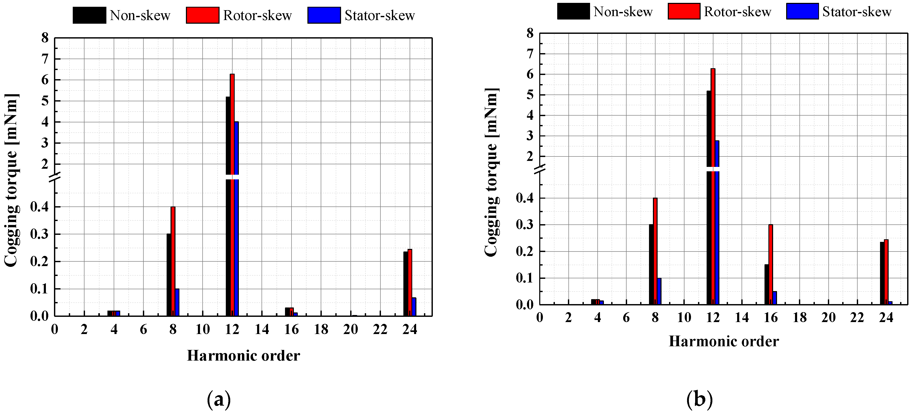
In the EPS system, the unit of required cogging values has mNm. For this reason, the cogging value of the motor in the EPS system is highly sensitive to manufacturing tolerance. Therefore, it is reported that the cogging torque value of prototype increases relative to that of FEM result for motor design in an EPS system [16,17,25]. However, the measured waveform of prototypes in Figure 3b is expected to have various harmonic orders, compared to the waveform of FEM result in Figure 3a. Figure 4a,b shows the harmonic orders of Figure 3a,b, respectively.
For the harmonic orders of FEM results in Figure 4a, 24th orders of cogging torque in rotor and stator-skew model are deleted, compared to that of non-skew model. However, for the harmonic orders of measurement results in Figure 4b, 24th orders of cogging torque were generated in all 3 prototypes. The unintended harmonic orders of cogging torque, which are 8th, 12th and 16th, are able to ignore the cogging torque value less than 0.05 mNm in Figure 4a. However, for the unintended harmonic orders of measurement, results are generated with the considerable values in Figure 4b. Therefore, it is necessary to verify the causes of manufacturing disturbances for the unintended harmonic orders of cogging torque. In contrast to Figure 4a, the 1st order was generated in Figure 4b. This 1st order is the friction torque caused by bearing friction of all 3 prototypes [26].
3. Harmonic Order Analysis of Cogging Torque
3.1. Manufacturing Disturbances
Motor prototypes are generally manufactured based on the design results of dimensions and required tolerances for parts and assemblies in Figure 1 and Table 1. However, manufacturing disturbances are inevitable due to parts machining, magnetization of permanent magnet, assembly, and so on [16,17]. For this reason, mechanical drafting, which comprises the results of engineering products, including motor, includes the tolerances of IT (International Tolerance) and GD&T (Geometric Dimensioning and Tolerance) to regulate dimensions and geometrical relationships considering manufacturing capability [27].
However, the variation analysis of motor performance considering all tolerances in mechanical drafting is a huge time-consuming development process. In addition to this, it is impossible for this process to consider all tolerances shown mechanical drafting for the variation analysis of motor performance. Therefore, it is necessary to survey past studies for manufacturing disturbance cases of motor performance variations. Table 5 shows the typical classification and causes of manufacturing disturbances [17].
In Table 5, there are three representative types of tolerance. First, dimension tolerance for the shapes of stator and rotor core. Second, assembly tolerance for the skew angle tolerance of core lamination. Third, tolerance of magnetic properties. Tolerance of magnetic properties corresponds to the magnet residual flux Br variation due to the manufacturing disturbances. For this reason, manufacturing disturbances are determined as follows:
- Dimension: Eccentricity on external diameter of rotor, and slot opening of stator;
- Assembly: skew angle.
- Magnetization of permanent magnet
: Magnetic residual flux Br of permanent magnet;
3.2. Magnetization Disturbances
Magnetic residual flux densities of rotor surface for three prototypes were measured to verify the unintended harmonic orders of cogging torque due to the manufacturing disturbances of magnetization for a permanent magnet. Figure 5a shows the measurement equipment of surface flux density on the 1st step of rotor for rotor-skew prototype. Figure 5b shows the 1st step position of measurement probe into axial direction. Figure 5c show the measurement position into radial direction. In Figure 5c, surface flux density is measured along the rotor surface show in green curve.
Figure 6a shows the measured waveform in measurement equipment. In Figure 6b, the numbers correspond to the center number of each pole in Figure 5c.
Based on the results of the measured surface flux density on the rotor in Figure 6, Figure 7 shows the average values of surface flux density for the step and pole of the rotor. Figure 7a–c corresponds to the non-skew, rotor-skew, and stator-skew prototypes, respectively. The average values of surface flux density on the rotor are different for each step and pole, as shown in Figure 7. Therefore, the unintended harmonics of cogging torque are expected to be generated due to the manufacturing disturbances for magnetization of the permanent magnet.
Based on the results of Figure 7, magnetic flux density in the magnet of rotor is calculated to verify the magnetization disturbances by using Equation (3). In Equation (3), Br is the magnetic residual flux density provided in permanent magnet supplier, as shown Table 1. Bgij denotes the average values of surface flux density on rotor measured in each ith rotor for jth step of rotor. Brij is the magnetic residual flux density of ith pole for jth step of rotor generated by Bgij. Figure 8a–c corresponds to the 1st, 2nd, and 3rd step for rotor-skew prototype, respectively.
Figure 8a–c corresponds to the allocation values of Br on the 1st, 2nd, and 3rd step for rotor-skew prototype by calculating (3), respectively.
3.3. Disturbances for the Dimension and Assembly
The shapes for three prototypes were measured to verify the unintended harmonic orders of cogging torque due to the manufacturing disturbances of dimension and assembly. Firstly, this involved the skew angle disturbances for the manufacturing disturbances of assembly. In case of rotor-skew prototype, step skew angles were phase differences based on the measured waveforms of surface flux density on each step of rotor as shown Figure 9. The measured step skew angles are 6.0 and 3.0 degrees, compared to the design value 5 degrees, as shown in Table 3.
In case of the stator-skew prototype, the maximum angle was measured from vertexes on the tooth tip on the top and bottom surfaces of stator core lamination, as shown in Figure 10. The measured angle was 14 degrees, compared to the design value of 15 degrees in Table 3.
Second, this involved dimension disturbances due to the manufacturing disturbances of part machining. Figure 11a,b shows the design values of slot opening in stator and eccentricity in the rotor for dimensions of part machining, respectively. These dimensions for eccentricity and slot opening decided by part machining are the key design factors to reduce cogging torque [10,11]. For this reason, these dimensions should be verified through measurements.
Figure 12 shows the measurement results of eccentricity for three prototypes as shown in the blue dotted circle of Figure 11a. In Figure 12, black and red curves show the design values and measurement results, respectively. The blue curve in Figure 12 means the results averaged the measured results, which are the measured results in red curves. The measured result ranges for eccentricity and slot opening are 8.5~9.0 mm and 2.0~2.2 mm, respectively.
3.4. Harmonic Order Analysis
Based on the measured results for the manufacturing disturbances of dimension and assembly in Section 3.3, the unintended harmonic orders of cogging torque are analyzed through an FEA analysis.
Figure 13 shows the harmonic orders of cogging torque for the measured magnetic residual flux density in Figure 8 and skew angle in Figure 9 and Figure 10. In Figure 13, the unintended harmonic orders of cogging torque, which are 8th, 12th, and 24th, are verified for the unintended harmonic orders of prototypes as shown Figure 4b.
In Figure 14a,b, the measured results for manufacturing disturbances of part machining are applied to eccentricity and slot opening, respectively. Figure 14a shows the measured result 8 mm of eccentricity in the red arc compared to the design value of 9 mm in the blue arc. Figure 14b shows the measured result 2.2 mm in red, compared to the design value 2 mm in blue.
Figure 15a shows the harmonic analysis of cogging torque applied to the eccentricity disturbance for the measured Br and skew-angle of Figure 13. Figure 15b shows the harmonic analysis of cogging torque applied to the slot opening disturbance for the measured Br and skew-angle of Figure 13. In Figure 15a, the reduction of eccentricity decreases the length of air gap over in rotor.
The reduction of air gap decreases the magnetic reluctance [14]. For this reason, the harmonic orders of cogging torque in Figure 15a increased. Figure 15b shows the harmonic orders of cogging torque considering the slot opening disturbance base on the results of Figure 15a. In contrast to Figure 15a, 16th order of cogging torque is verified due to the slot opening disturbance.
3.5. Analysis Results
The unintended harmonic orders of cogging torque for the IPMSM prototypes were verified as 8th, 12th, 16th, and 24th based on the results of measurement and FEM considering manufacturing disturbances in Section 3.3. These causes of unintended harmonic orders of cogging torque were also verified as the manufacturing disturbances of permanent magnet magnetization, skew-angle, eccentricity, and slot opening. However, conventional analysis method analyzes the harmonic order of cogging torque for the ideal design results, as shown in Table 1.
Therefore, the unintended harmonic orders of cogging torque are not able to be analyzed because the conventional method does not deal with the manufacturing disturbances for protypes. In this paper, the analysis process is proposed for the unintended harmonic order of cogging torque in the following steps: measurement of cogging torque for prototypes, selection of manufacturing disturbances, and FEM verification of cogging torque considering manufacturing disturbances. The unintended harmonic orders of cogging torque were verified by using the proposed analysis process.
4. Conclusions
This paper dealt with the unintended harmonic orders of cogging torque for the IPMSM of an EPS system. Firstly, the intended harmonic orders of cogging torque are verified based on the measurement results of three prototypes with non-skew, rotor-skew, and stator-skew. In order to verify the causes of the unintended harmonic orders for cogging torque of three prototypes, the unintended harmonic orders, which are 8th, 12th, 16th, and 24th, are analyzed by FEA results based on the measurement results for manufacturing disturbances.
The 8th, 12th, and 24th orders are verified as the causes of manufacturing disturbances for permanent magnet magnetization, skew-angle, and eccentricity. The 16th order is also verified as the cause of manufacturing disturbances for slot opening. For this reason, the unintended harmonic orders and their manufacturing disturbances should be verified to suppress cogging torque to enhance the motor performance in an EPS system.
Author Contributions
Conceptualization, C.-S.L.; methodology, C.-S.L.; software, C.-S.L.; validation, C.-S.L.; formal analysis, C.-S.L.; investigation, C.-S.L.; resources, C.-S.L.; data curation, C.-S.L.; writing—original draft preparation, C.-S.L.; writing—review and editing, H.-J.K.; visualization, H.-J.K.; supervision, H.-J.K.; and project administration, H.-J.K. All authors have read and agreed to the published version of the manuscript.
Funding
This research received no external funding.
Institutional Review Board Statement
Not applicable.
Informed Consent Statement
Not applicable.
Data Availability Statement
Not applicable.
Conflicts of Interest
The authors declare no conflict of interest.
References
- Bebregergis, A.; Chowdhury, M.H.; Islam, M.S.; Sebastian, T. Modeling of permanent-magnet synchronous machine including torque ripple effects. IEEE Trans. Ind. Appl. 2015, 51, 232–239. [Google Scholar] [CrossRef]
- Yang, H.; Ademin, S.; Mcmahon, R.-A. Comparative study on multiple three-phase permanent magnet motors in fault tolerance electric power steering application. In Proceedings of the 10th International Conference on Power Electronics, Machines and Drives (PEMD 2020), Online Conference, 15–17 December 2020; p. 15022020. [Google Scholar]
- Islam, M.S.; Mikail, R.; Kabir, M.A.; Husain, I. Torque Ripple and Radial Force Minimization of Fractional Slot Permanent Magnet Machines Through Stator Harmonic Elimination. IEEE Trans. Electr. 2022, 8, 1072–1084. [Google Scholar] [CrossRef]
- Wu, L.-J.; Zhu, Z.-Q.; Staton, D.-A.; Popescu, M.; Hawkins, D. Comparison of analytical models of cogging torque in surface-mounted PM machines. IEEE Trans. Ind. Electr. 2012, 59, 2414–2425. [Google Scholar] [CrossRef]
- Lee, C.-S.; Jung, G.-T.; Hong, J.-P.; Kim, H.-J.; Kim, Y.-K. Design of brushless permanent machine with skewed stator for electrical power steering system. J. Korean Mag. 2015, 25, 189–197. [Google Scholar] [CrossRef]
- Jiang, J.-W.; Bilgin, B.; Yang, Y.; Sathyan, A.; Dakhad, H.; Emadi, A. Rotor skew pattern design and optimization for cogging torque reduction. IET Electr. Syst. Trans. 2015, 6, 126–135. [Google Scholar] [CrossRef]
- Chen, W.; MA, J.; Wu, G.; Fang, Y. Torque ripple reduction of a salient-pole permanent magnet synchronous machine with an advanced step-skewed rotor design. IEEE Access 2020, 8, 118989–118999. [Google Scholar] [CrossRef]
- Wang, S.; Niu, S.; Zhao, X.; Fu, W. Novel dc-saturation-relieving hybrid reluctance machine with skewed permanent magnets for electric vehicle propulsion. IEEE Trans. Mag. 2022, 58, 1–5. [Google Scholar] [CrossRef]
- Islam, M.S.; Mir, S.; Sebastian, T. Issues in reducing the cogging torque of mass-produces permanent magnet brushless DC motor. IEEE Trans. Ind. Appl. 2004, 40, 813–820. [Google Scholar] [CrossRef]
- Hendershot, J.-R.; Miller, T.J.-E. Design of Brushless Permanent-Magnet Machines, 2nd ed.; Motor Design Books LLC: Venice, FL, USA, 2013; pp. 229–232. [Google Scholar]
- Wu, L.-J.; Zhu, Z.-Q.; Staton, D.; Popescu, D.; Hawkins, D. Analytical cogging torque prediction for surface-mounted PM machines accounting for different slot sizes and uneven positions. In Proceedings of the 2011 IEEE International Electric Machines & Drives Conference (IEMDC), Niagara Falls, ON, Canada, 15–18 May 2011; p. 15032021. [Google Scholar]
- García-Gracia, M.; Romero, A.-J.; Ciudad, J.-H. Cogging torque reduction based on a new pre-slot technique for a small wind generator. Energies 2018, 11, 3219. [Google Scholar] [CrossRef] [Green Version]
- Islam, R.; Husain, I.; Fardoun, A.; Mclaughlin, K. Permanent-magnet synchronous motor magnet designs with skewing for torque ripple and cogging torque reduction. IEEE Trans. Ind. Appl. 2009, 45, 152–160. [Google Scholar] [CrossRef]
- Zhou, Y.; Li, H.; Zhou, S.; Cao, Q. Analytical calculation of magnetic field and cogging torque in surface-mounted permanent-magnet machine accounting for any eccentric rotor shape. IEEE Trans. Ind. Appl. 2015, 62, 3438–3447. [Google Scholar] [CrossRef]
- Wang, K.; Zhu, Z.-Q.; Ombach, G.; Chlebosz, W. Average torque improvement of interior permanent-magnet machine using third harmonic in rotor shape. IEEE Trans. Ind. Electron. 2014, 9, 5047–5057. [Google Scholar] [CrossRef]
- Park, H.-J.; Lim, M.-S.; Lee, C.-S. Magnet shape design and verification for SPMSM of EPS system using cycloid curve. IEEE Access. 2019, 7, 137207–137216. [Google Scholar] [CrossRef]
- Lee, C.-S.; Cha, K.-S.; Park, J.-S.; Lim, M.-S. Tolerance-insensitive design of the magnet shape for a surface permanent magnet synchronous motor. Energies 2020, 13, 1311. [Google Scholar] [CrossRef] [Green Version]
- Yoneda, A.; Miyoshi, T.; Shimizu, Y. Cogging torque target and design of motor for EPS. In Proceedings of the SAE World Congress & Exhibition, Detroit, MI, USA, 3–6 April 2006; p. 13012006. [Google Scholar]
- Ganesan, S.; David, P.-W.; Balachandran, P.-K.; Samithas, D. Intelligent starting current-based fault identification of an induction motor operating under various power quality issues. Energies 2021, 14, 304. [Google Scholar] [CrossRef]
- Lee, S.-G.; Kim, S.-G.; Park, J.-C.; Lee, T.-H.; Lim, M.-S. Robust design optimization of SPMSM for robotic actuator considering assembly imperfection of segmented stator core. IEEE Trans. Energy Convers. 2020, 35, 2076–2085. [Google Scholar] [CrossRef]
- Kim, K.-S.; Jung, K.-T.; Kim, J.-M.; Hong, J.-P.; Kim, S.-I. Taguchi robust optimum design for reducing the cogging torque of EPS motors considering magnetic unbalance caused by manufacturing of tolerances of PM. IET Electr. Power Appl. 2016, 10, 909–915. [Google Scholar] [CrossRef]
- Guo, H.; Wu, Z.; Qian, H.; Yu, K.; Xu, J. Statistical analysis on the additional torque ripple caused by magnet tolerances in surface-mounted permanent magnet synchronous motors. IET Electr. Power Appl. 2015, 9, 183–192. [Google Scholar] [CrossRef]
- Kim, Y.-K.; Hong, J.-P.; Hur, J. Torque characteristic analysis considering the manufacturing tolerance for electric machine by stochastic response surface method. IEEE Trans. Ind. Appl. 2003, 39, 713–719. [Google Scholar]
- Wu, J.; Wang, Y.-Y. A new technique for reducing cogging torque in EPS permanent magnet brushless DC motor. In Proceedings of the 2007 International Conference on Electrical Machines and Systems, Seoul, Korea, 8–11 October 2007; pp. 789–791. [Google Scholar]
- Kim, J.M.; Yoon, M.H.; Hong, J.P.; Kim, S.I. Analysis of cogging torque caused by manufacturing tolerances of surface-mounted permanent magnet synchronous motor for electric power steering. IET Electr. Power Appl. 2016, 8, 691–696. [Google Scholar] [CrossRef]
- Hwang, S.-W.; Lim, M.-S.; Hong, J.-P. Hysteresis torque estimation method based on iron-loss analysis for permanent magnet synchronous motor. IEEE Trans. Magn. 2016, 52, 1–4. [Google Scholar] [CrossRef]
- ASME. Geometric Dimensioning and Tolerancing Y14.5, 2018 ed.; ASME: New York, NY, USA, 2019; pp. 10–30. [Google Scholar]
Figure 1.
Shape of prototype model: (a) cross sectional view with 1/4 model; (b) stack length.
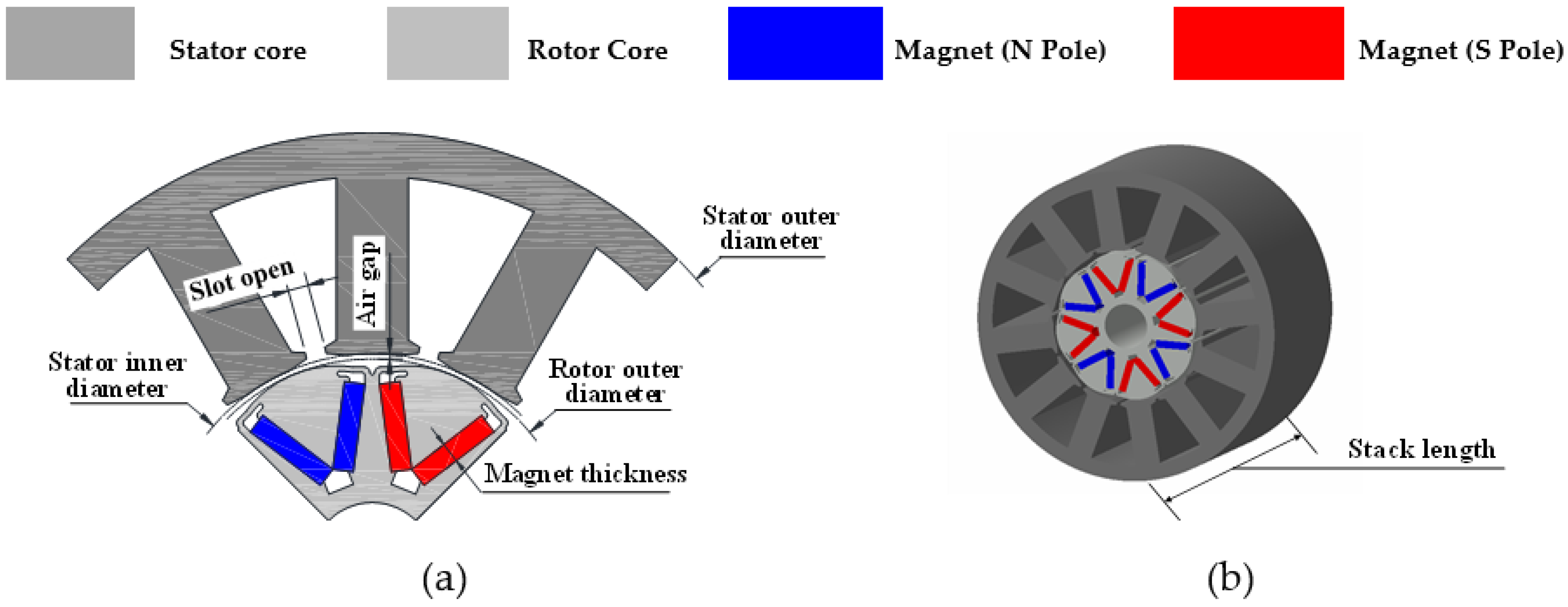
Figure 2.
Test equipment for the measurement of cogging torque: (a) measurement equipment; (b) assembling prototype in measurement equipment; and (c) measurement monitor.
Figure 2.
Test equipment for the measurement of cogging torque: (a) measurement equipment; (b) assembling prototype in measurement equipment; and (c) measurement monitor.
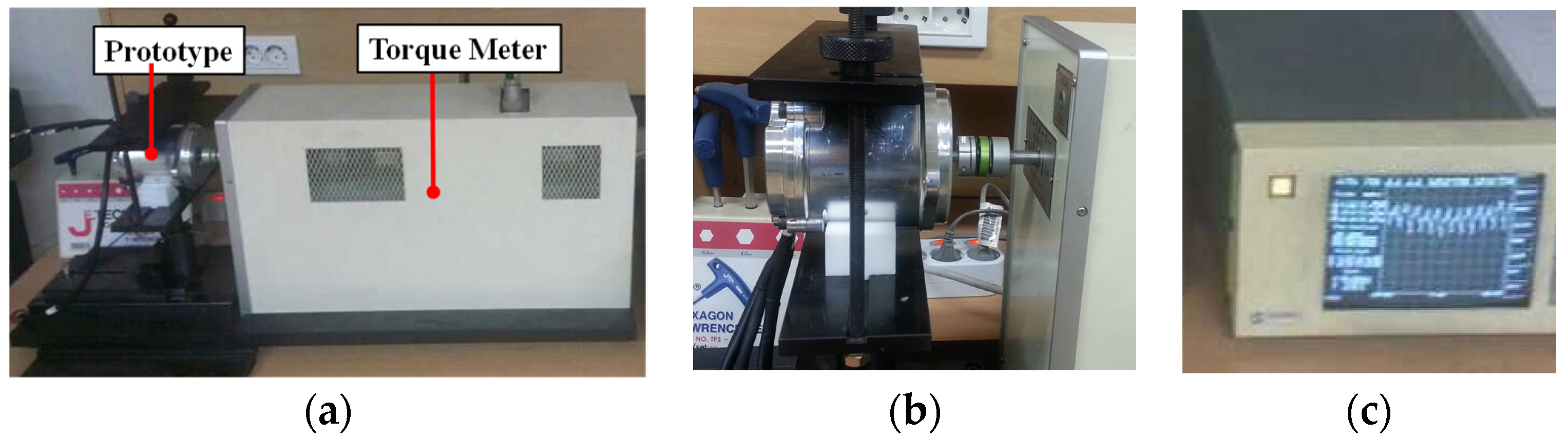
Figure 3.
Waveform of the cogging torque for the results of FEA and measurement: (a) waveform of cogging torque for the FEA; (b) waveform of the cogging torque for the measurement.
Figure 3.
Waveform of the cogging torque for the results of FEA and measurement: (a) waveform of cogging torque for the FEA; (b) waveform of the cogging torque for the measurement.
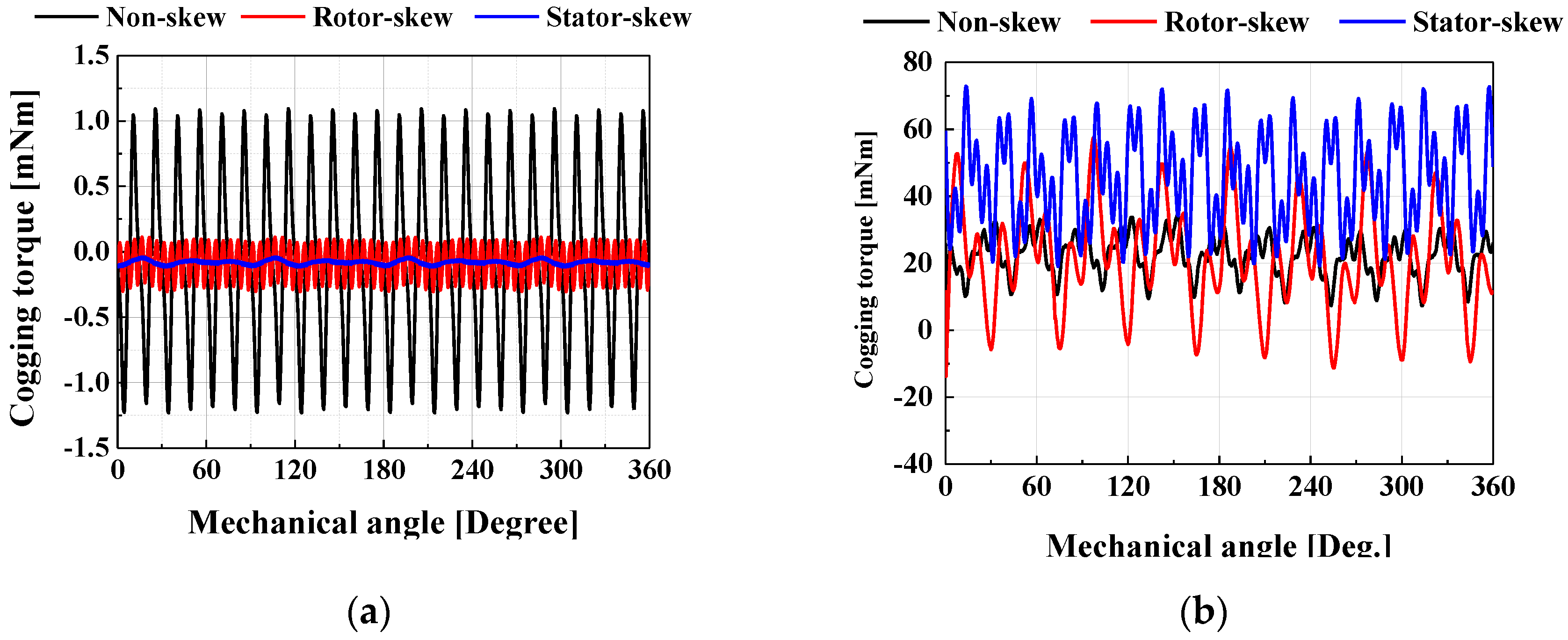
Figure 4.
Harmonic order of the cogging torque for the results of FEA and measurement: (a) harmonic order of cogging torque for the FEA; (b) harmonic order of the cogging torque for the measurement.
Figure 4.
Harmonic order of the cogging torque for the results of FEA and measurement: (a) harmonic order of cogging torque for the FEA; (b) harmonic order of the cogging torque for the measurement.
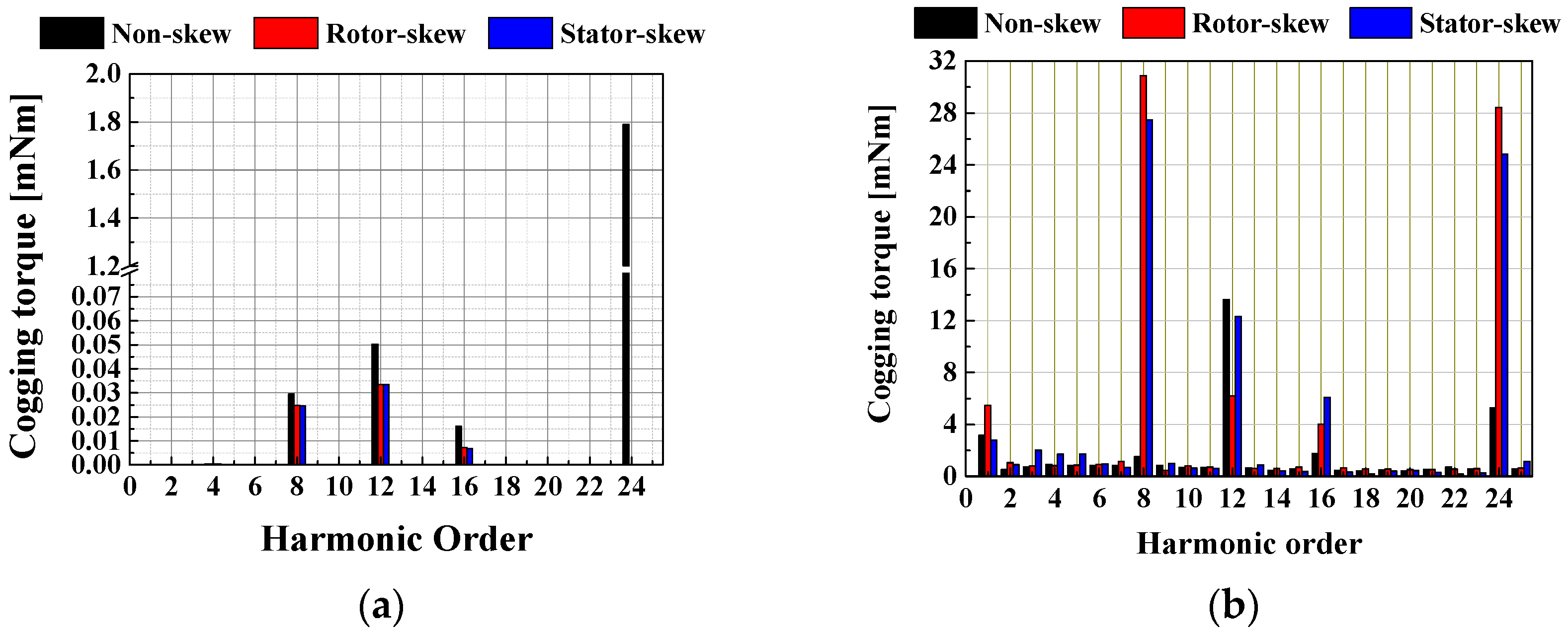
Figure 5.
Measurement equipment and position for the flux density on the rotor surface: (a) measurement equipment; (b) measurement position into axial direction; and (c) measurement position into radial direction.
Figure 5.
Measurement equipment and position for the flux density on the rotor surface: (a) measurement equipment; (b) measurement position into axial direction; and (c) measurement position into radial direction.
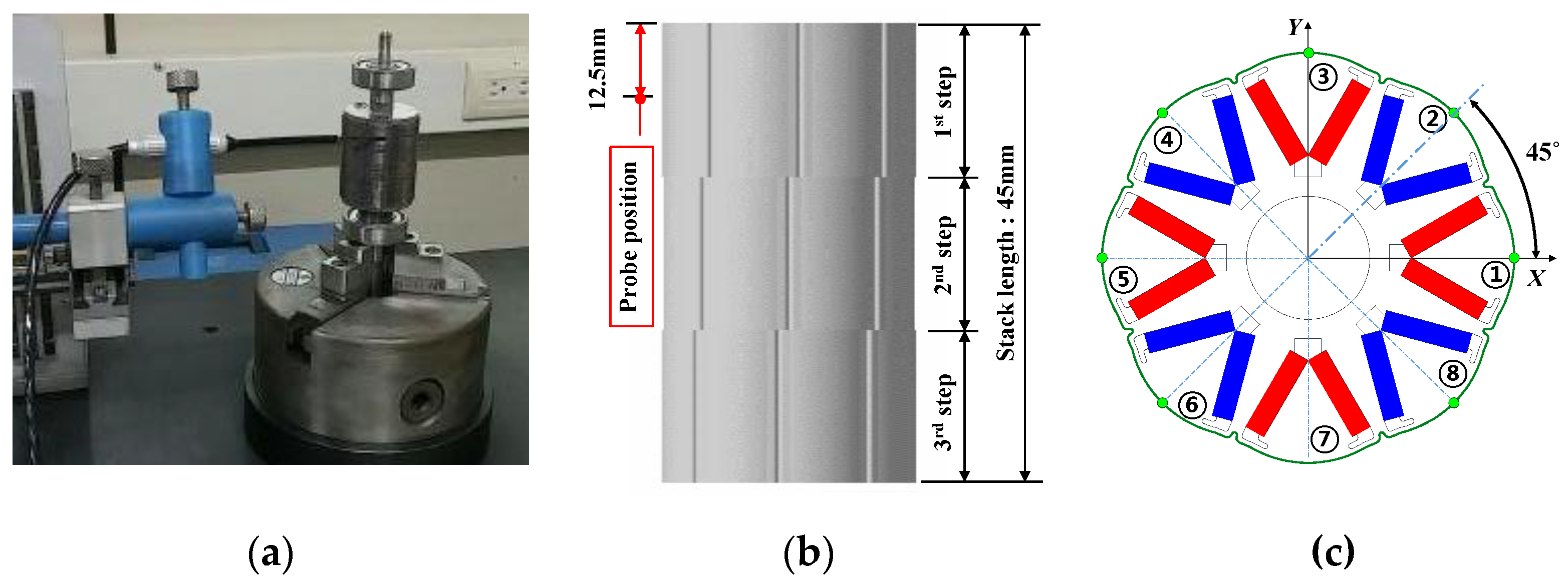
Figure 6.
Measurement of waveform for the magnetic flux density on the rotor surface: (a) wave form of measurement equipment; (b) waveform of eight poles for the rotor.
Figure 6.
Measurement of waveform for the magnetic flux density on the rotor surface: (a) wave form of measurement equipment; (b) waveform of eight poles for the rotor.
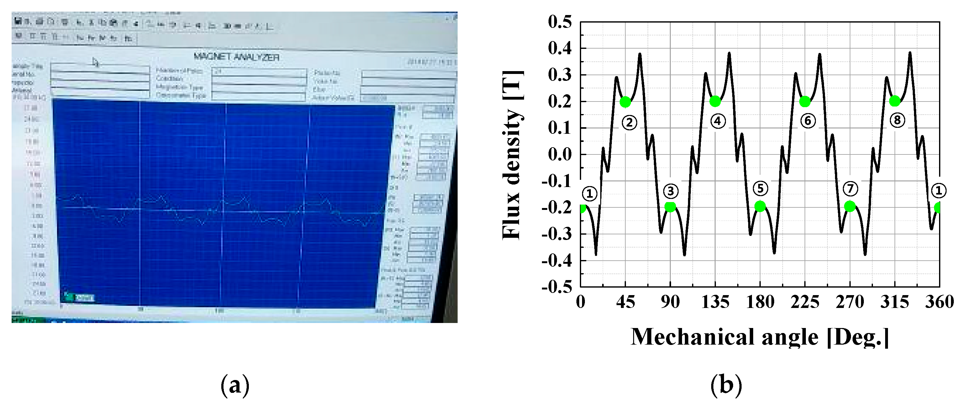
Figure 7.
Flux density of each pole on the rotor surface of three prototypes: (a) non-skew; (b) rotor-skew; and (c) stator-skew.
Figure 7.
Flux density of each pole on the rotor surface of three prototypes: (a) non-skew; (b) rotor-skew; and (c) stator-skew.
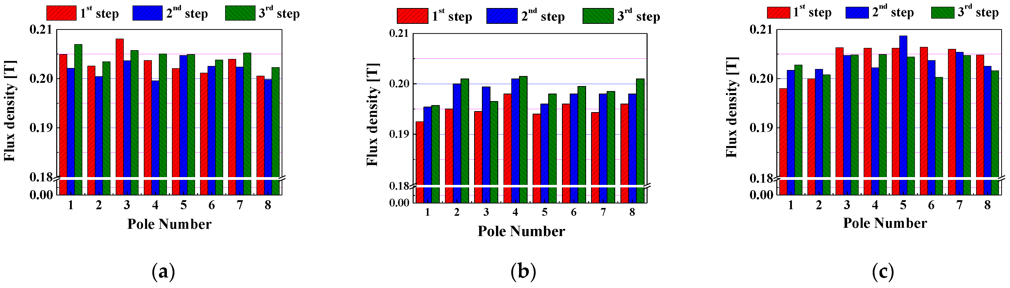
Figure 8.
Allocation of the unbalanced remanent flux density in the rotor-skew prototype: (a) 1st step; (b) 2nd step; and (c) 3rd step.
Figure 8.
Allocation of the unbalanced remanent flux density in the rotor-skew prototype: (a) 1st step; (b) 2nd step; and (c) 3rd step.
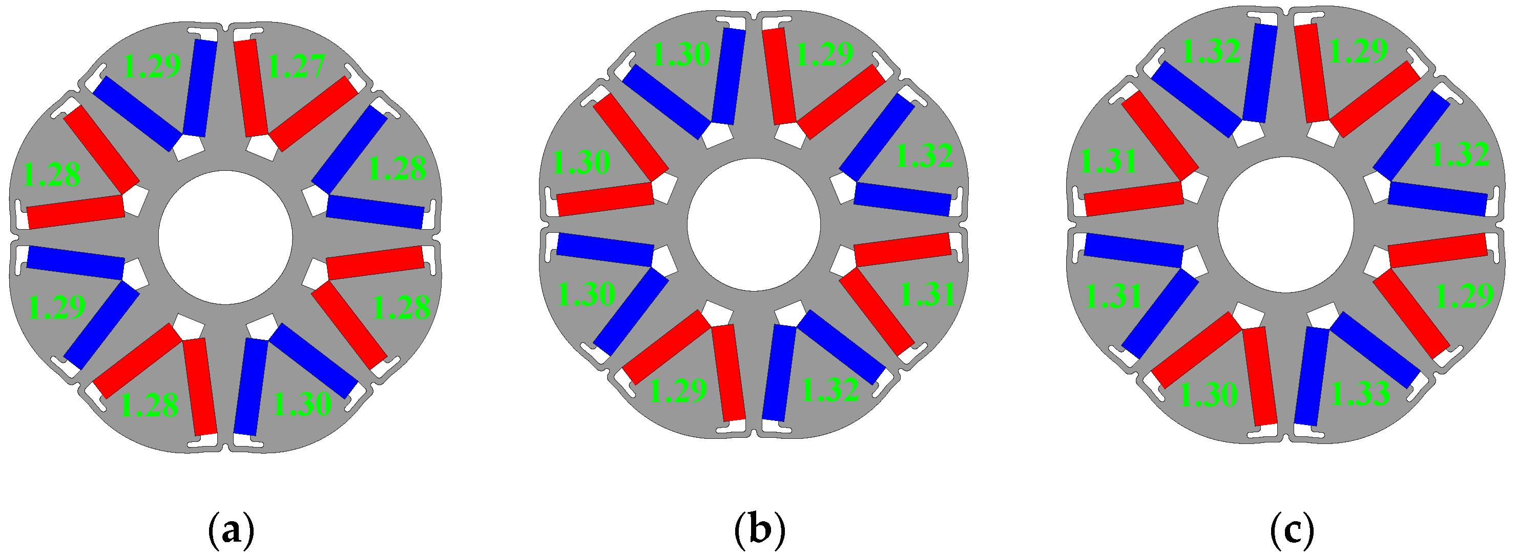
Figure 9.
Measurement of the step-skew angle for the rotor-skew prototype: (a) rotor-skew prototype; (b) measurement of step skew angle.
Figure 9.
Measurement of the step-skew angle for the rotor-skew prototype: (a) rotor-skew prototype; (b) measurement of step skew angle.
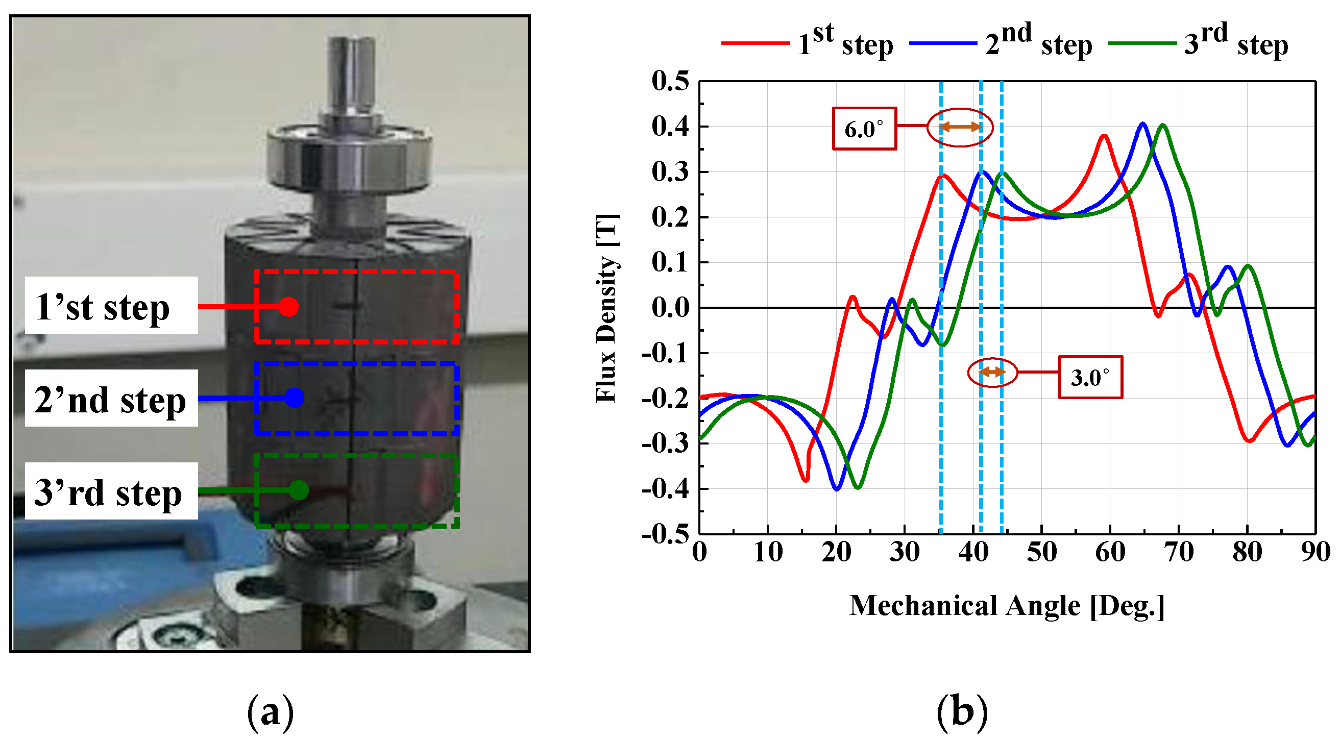
Figure 10.
Measurement of the continuous skew angle for the stator-skew prototype: (a) stator-skew prototype; (b) measured skew angle.
Figure 10.
Measurement of the continuous skew angle for the stator-skew prototype: (a) stator-skew prototype; (b) measured skew angle.
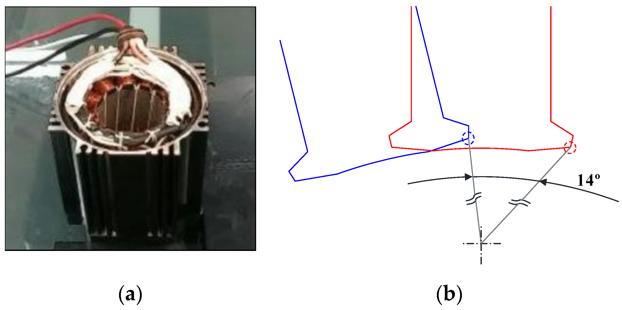
Figure 11.
Design values of eccentricity and slot opening: (a) eccentricity; (b) slot opening.
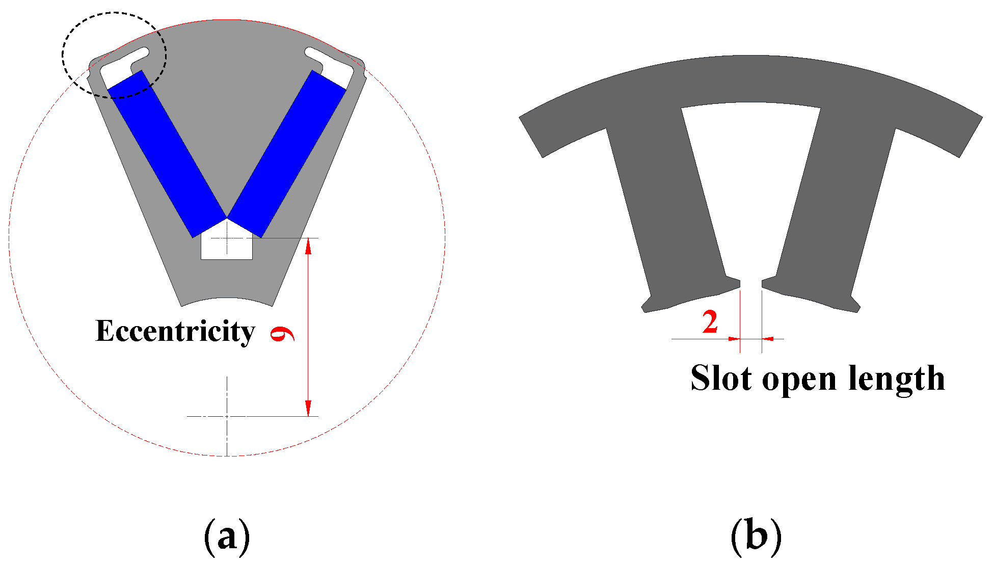
Figure 12.
Measurement of eccentricity: (a) non-skew; (b) rotor-skew; and (c) stator-skew.
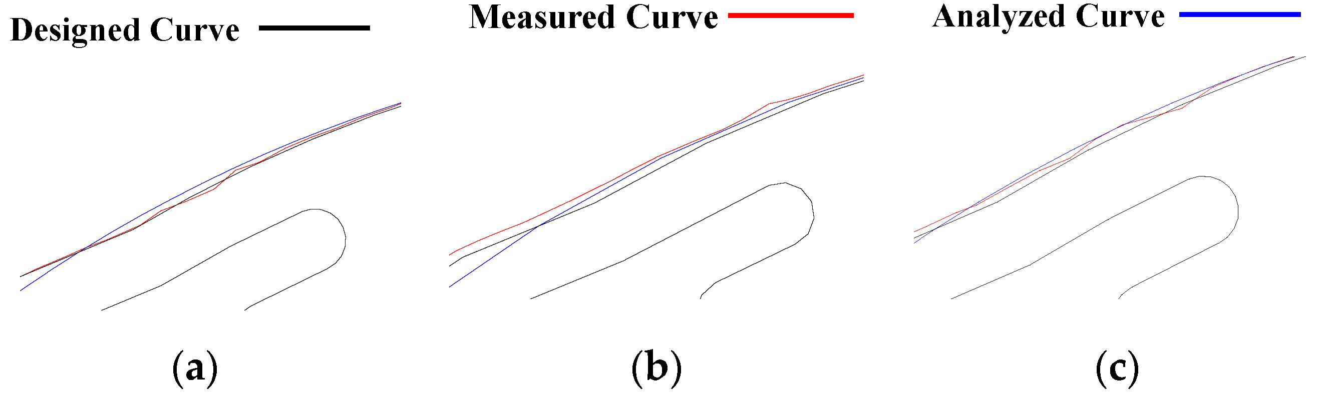
Figure 13.
Harmonic order results with the measured Br and skew angle.
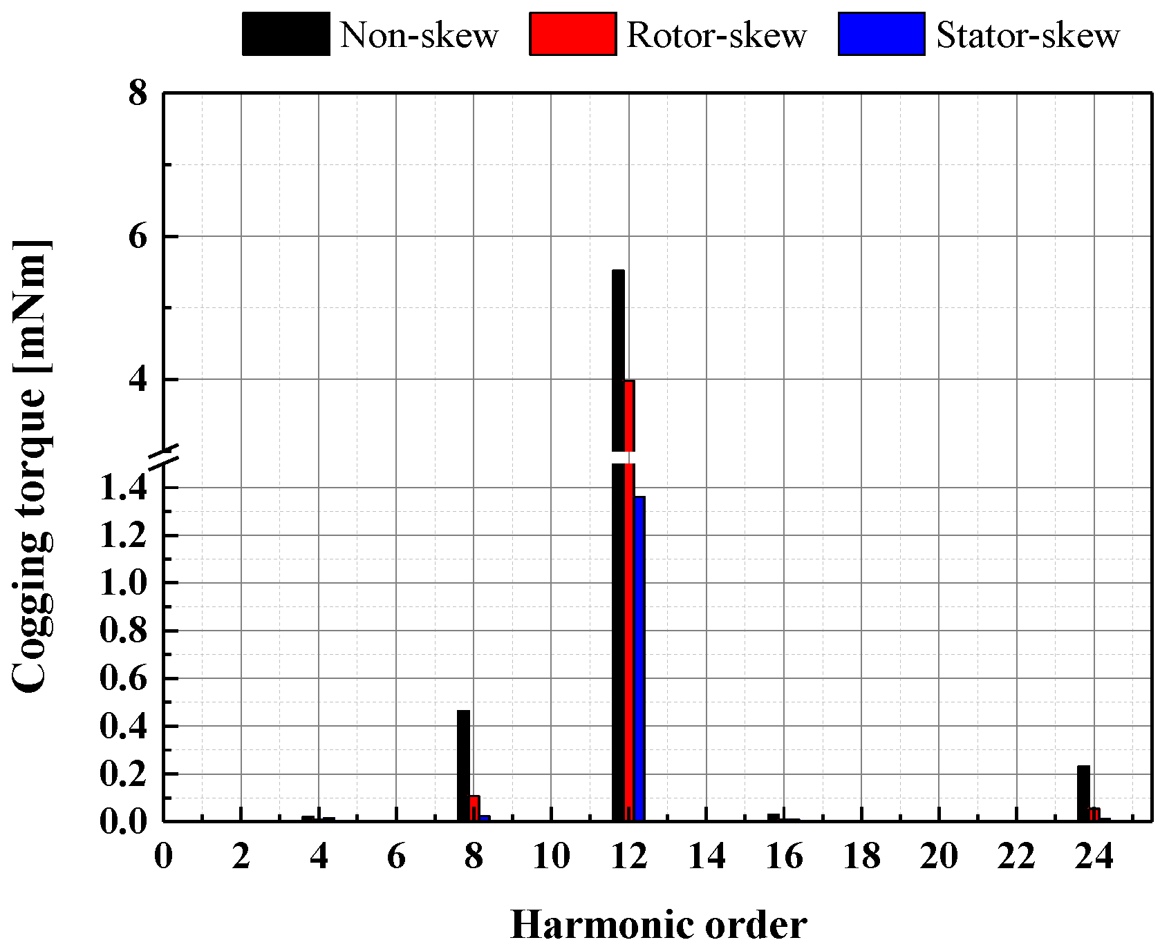
Figure 14.
Allocation of the measured eccentricity and slot opening: (a) eccentricity; (b) slot opening.
Figure 14.
Allocation of the measured eccentricity and slot opening: (a) eccentricity; (b) slot opening.

Figure 15.
Harmonic order analysis considering measured Br, skew-angle, eccentricity and slot opening: (a) measured Br, skew-angle and eccentricity; (b) measured Br, skew-angle, eccentricity and slot opening.
Figure 15.
Harmonic order analysis considering measured Br, skew-angle, eccentricity and slot opening: (a) measured Br, skew-angle and eccentricity; (b) measured Br, skew-angle, eccentricity and slot opening.

Table 1.
Design specification of prototype.
| Classification | Unit | Value | Classification | Unit | Value |
|---|---|---|---|---|---|
| Type | - | IPMSM | Air gap | mm | 0.5 |
| Phase/Pole/Slot | - | 3/8/12 | Rotor diameter | mm | 40 |
| Stator outer diameter | mm | 84 | Stack length | mm | 45 |
| Stator inner diameter | mm | 41 | Magnet thickness | mm | 2 |
| Slot opening | mm | 2 | Magnet Br | T | 1.3 |
Table 2.
3D and prototypes with the different skew designs.
| Skew | Stator | Rotor | ||
|---|---|---|---|---|
| Non-skew |  |  |  |  |
| 3D | Prototype | 3D | Prototype | |
| Skew |  | 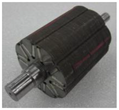 |  | 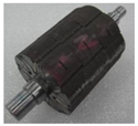 |
| 3D | Prototype | 3D | Prototype | |
Table 3.
Skew designs for the 3 prototypes.
| Prototype | Non-Skew | Stator-Skew | Rotor-Skew |
|---|---|---|---|
| Stator | Not applied | Nstep = 1 θskew = 15° | Not applied |
| Rotor | Not applied | Not appplied | Nstep = 3 θskew = 5° |
Table 4.
Skew designs for the 3 prototypes.
| Model | FEA [mNm] | Prototype [mNm] |
|---|---|---|
| Non-skew | 2.3 | 34.6 |
| Rotor-skew | 0.4 | 54.9 |
| Stator-skew | 0.1 | 71.0 |
Table 5.
Classification and causes for manufacturing disturbances of motor.
| Classification | Causes |
|---|---|
| Dimension Tolerance | Dimension of part due to machining method and condition - Stator/rotor dimension: stamping and wire-cutting - Magnet dimension: sintering, grinding, coating, etc. |
| Assembly Tolerance | Poor tolerance management for assembling parts - Step or continuous skew angle of core lamination Assembly method: interlocking, welding, and fitting - Magnet orientation or position: bonding and fitting |
| Material Property Tolerance | Magnet: disturbances due to magnetization method - Unbalanced magnetic direction and remanent flux density Core: disturbances due to poor stamping and welding - Deterioration of B-H curve data |
Publisher’s Note: MDPI stays neutral with regard to jurisdictional claims in published maps and institutional affiliations. |
© 2022 by the authors. Licensee MDPI, Basel, Switzerland. This article is an open access article distributed under the terms and conditions of the Creative Commons Attribution (CC BY) license (https://creativecommons.org/licenses/by/4.0/).
Share and Cite
MDPI and ACS Style
Lee, C.-S.; Kim, H.-J. Harmonic Order Analysis of Cogging Torque for Interior Permanent Magnet Synchronous Motor Considering Manufacturing Disturbances. Energies 2022, 15, 2428. https://doi.org/10.3390/en15072428
AMA Style
Lee C-S, Kim H-J. Harmonic Order Analysis of Cogging Torque for Interior Permanent Magnet Synchronous Motor Considering Manufacturing Disturbances. Energies. 2022; 15(7):2428. https://doi.org/10.3390/en15072428
Chicago/Turabian StyleLee, Chung-Seong, and Hae-Joong Kim. 2022. "Harmonic Order Analysis of Cogging Torque for Interior Permanent Magnet Synchronous Motor Considering Manufacturing Disturbances" Energies 15, no. 7: 2428. https://doi.org/10.3390/en15072428
Note that from the first issue of 2016, this journal uses article numbers instead of page numbers. See further details here.