
Novel Design of Six-Phase Spoke-Type Ferrite Permanent Magnet Motor for Electric Truck Application

 , ,
, ,
Abstract
:1. Introduction
2. Initial Motor Design and Validation
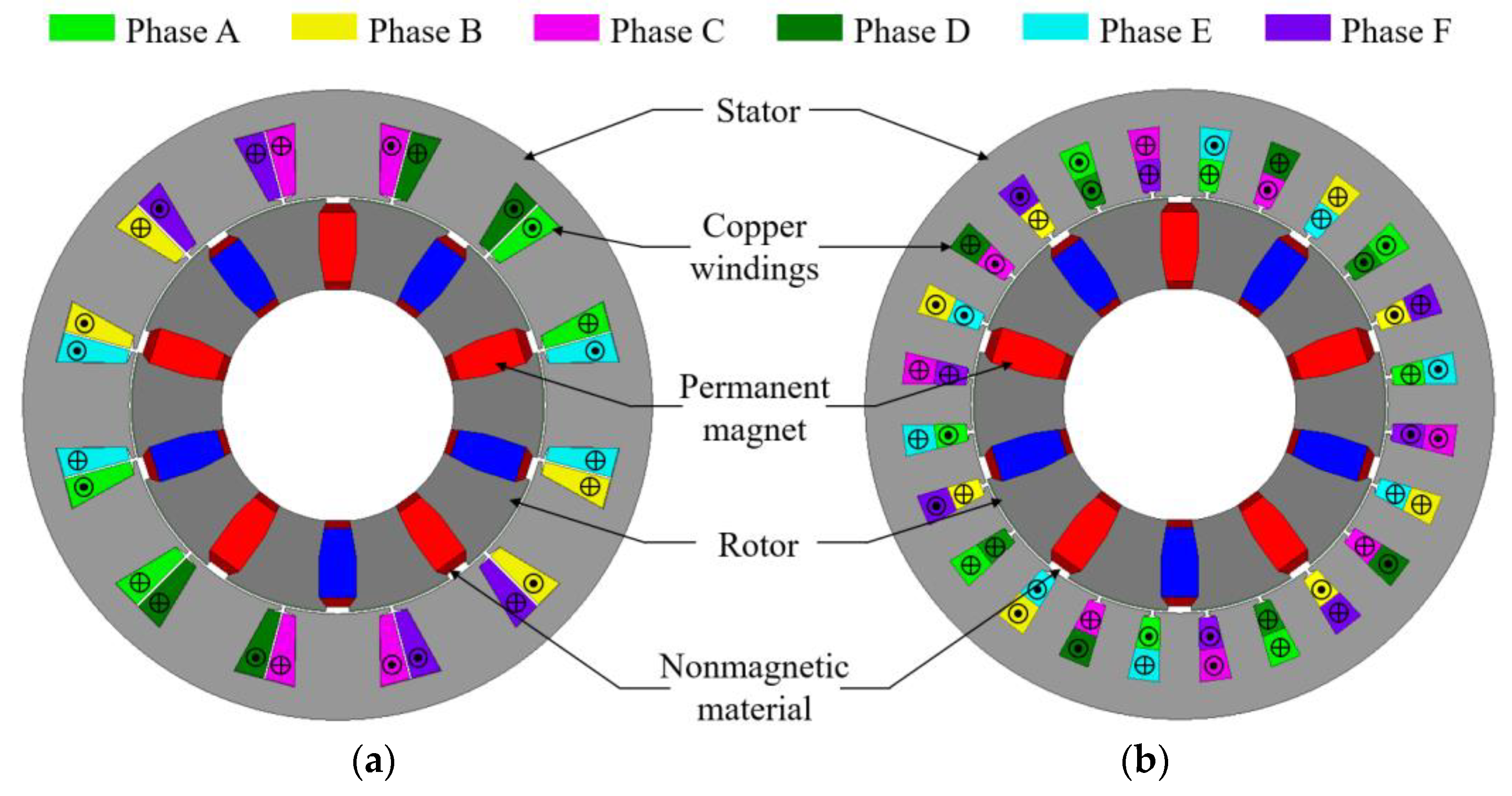
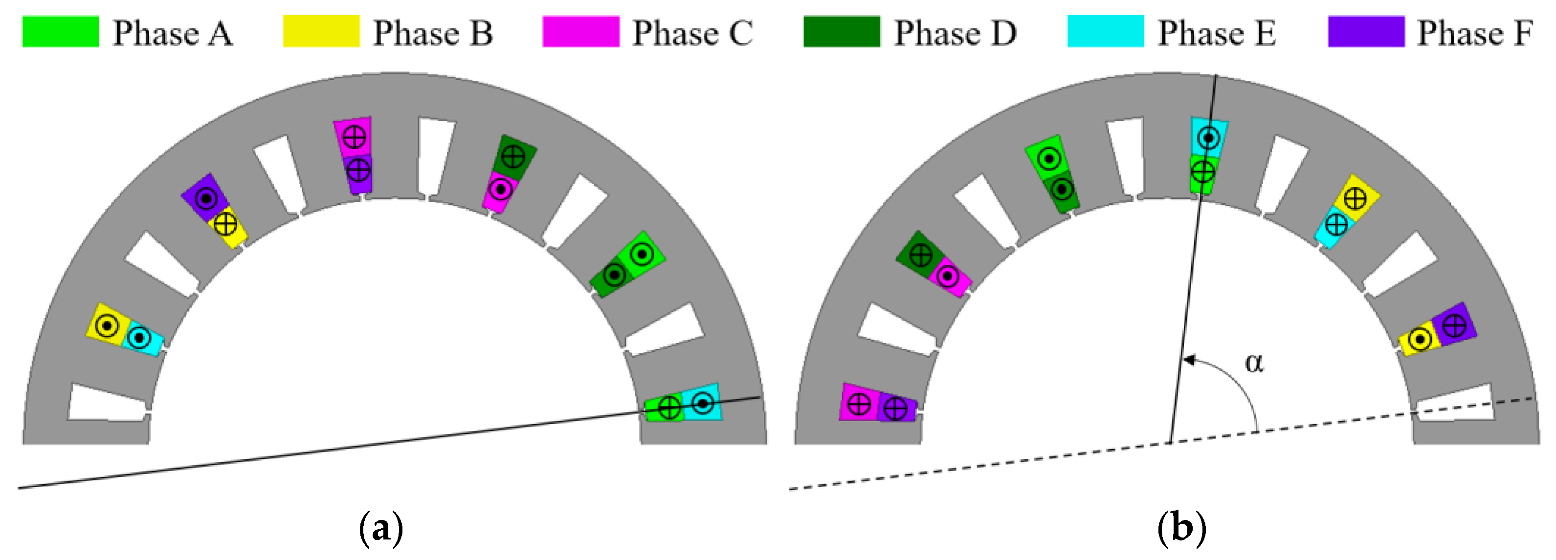
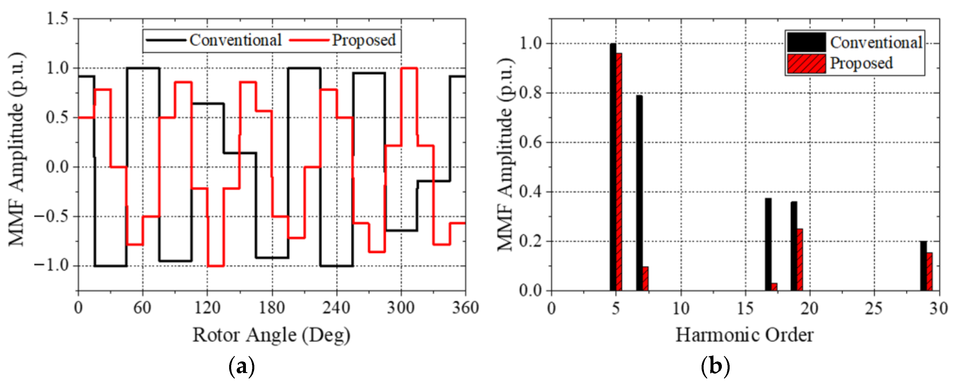
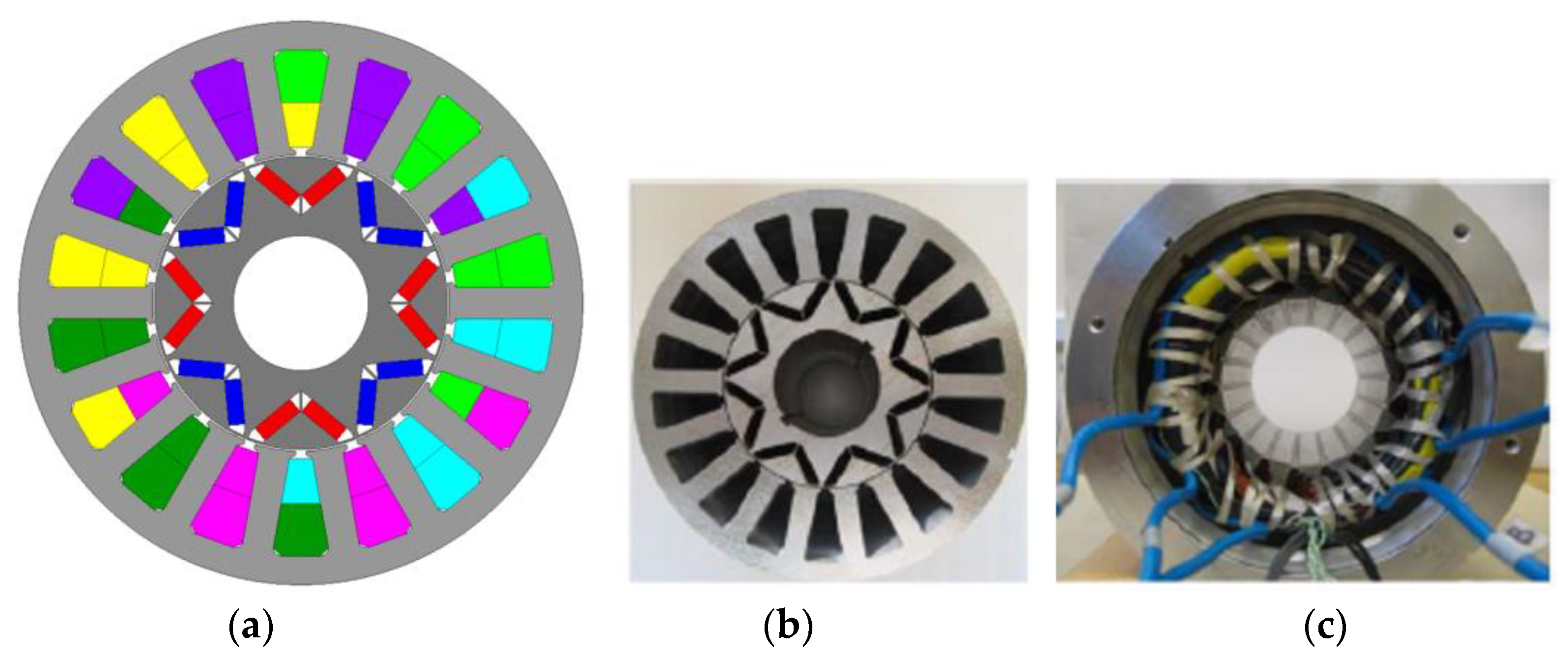
2.1. Winding Configuration
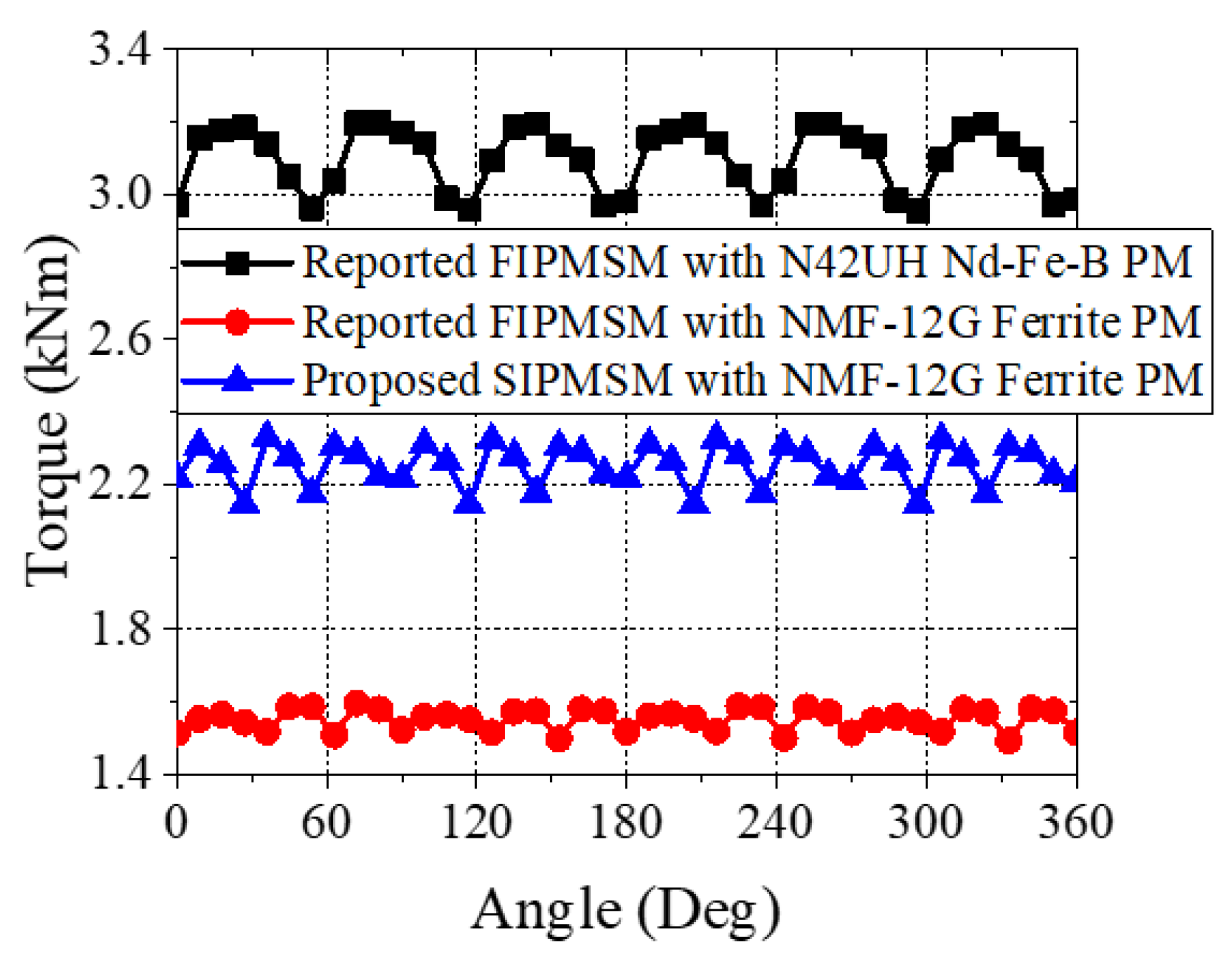
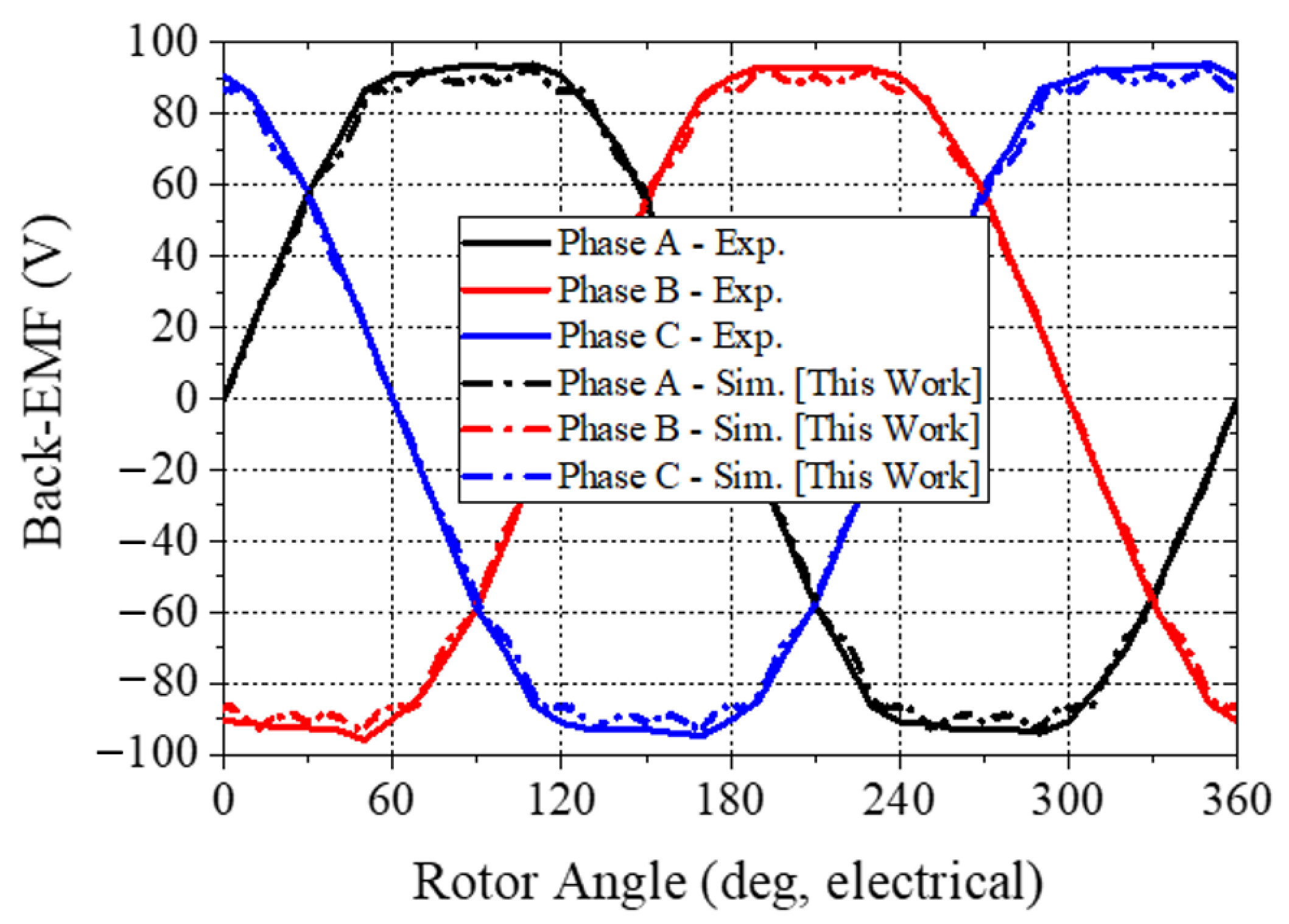
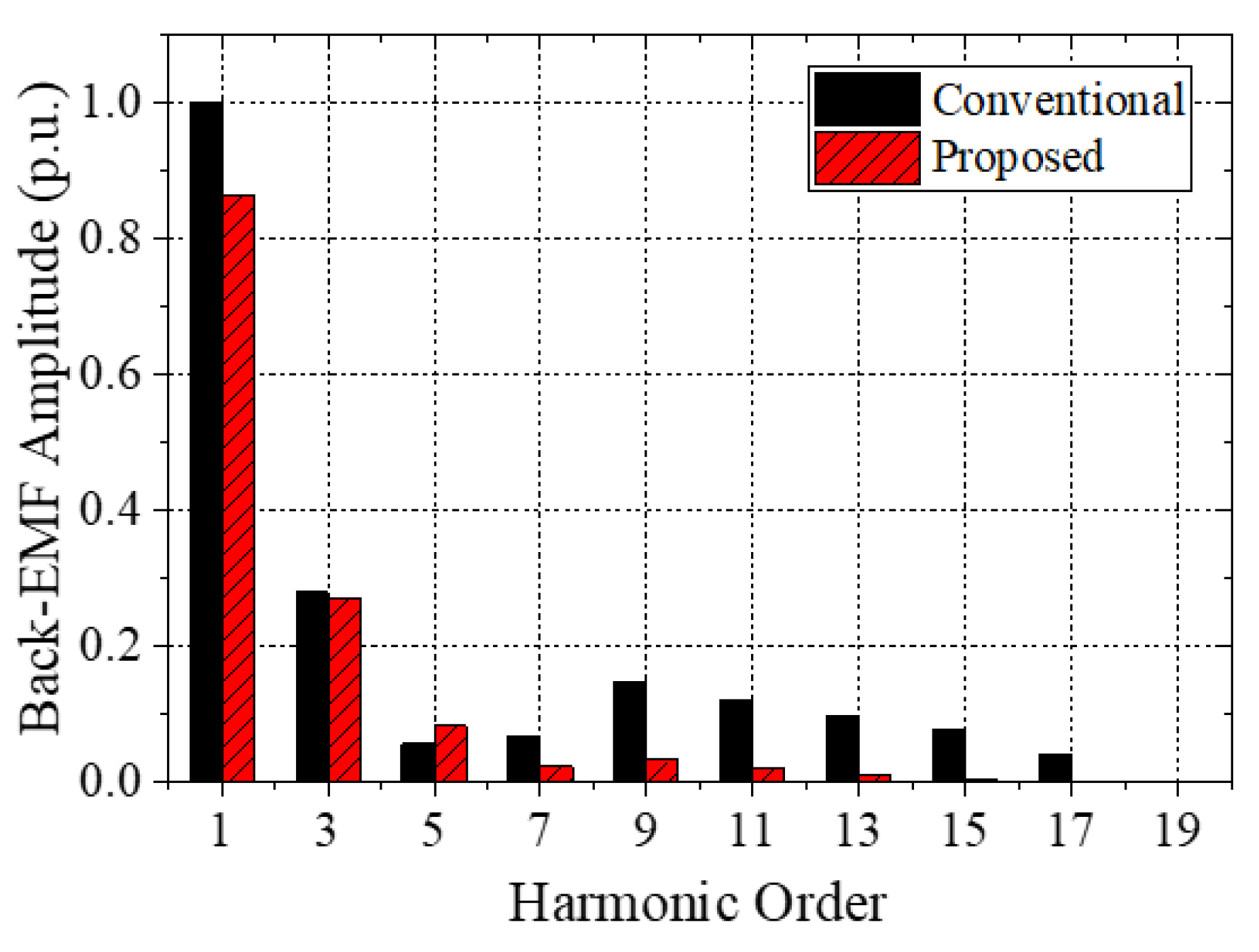
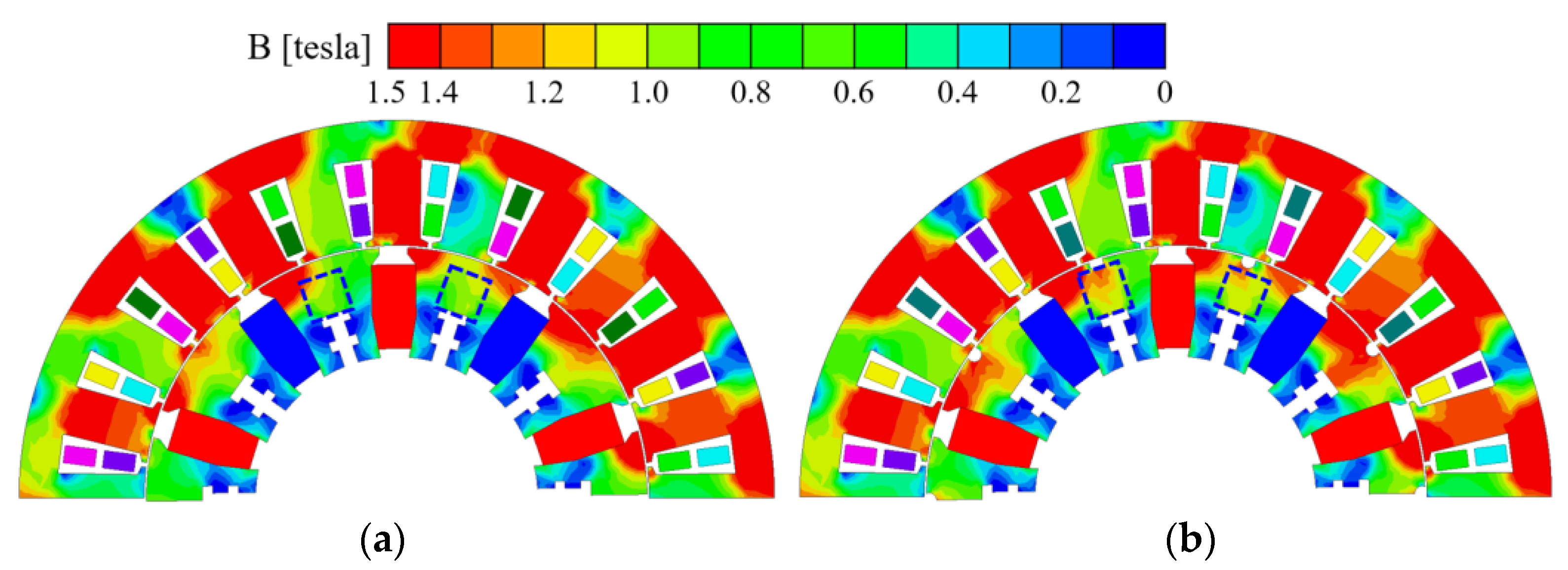
2.2. Electromechanical Performance Comparison
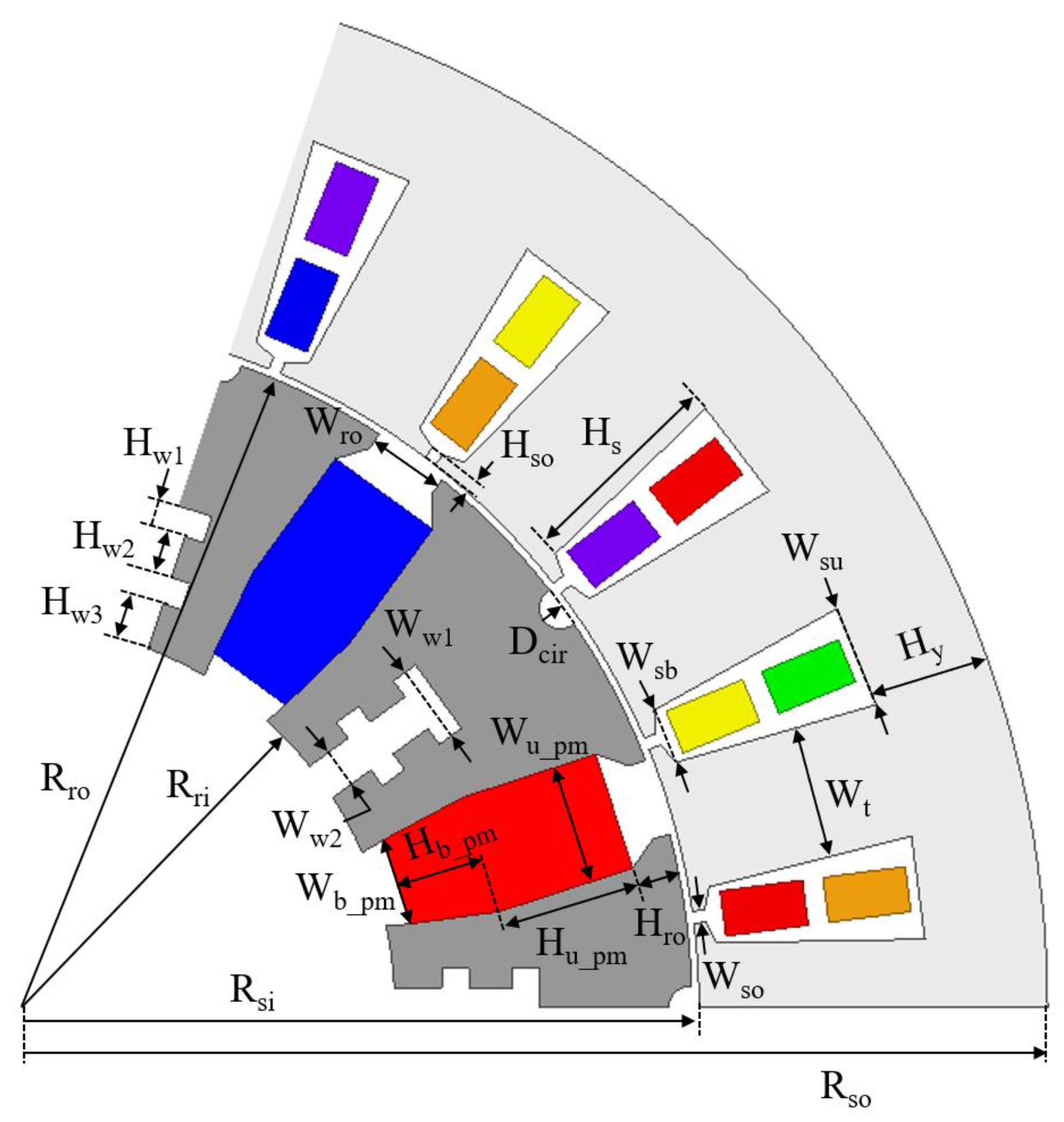
3. Optimal Motor Design and Specification
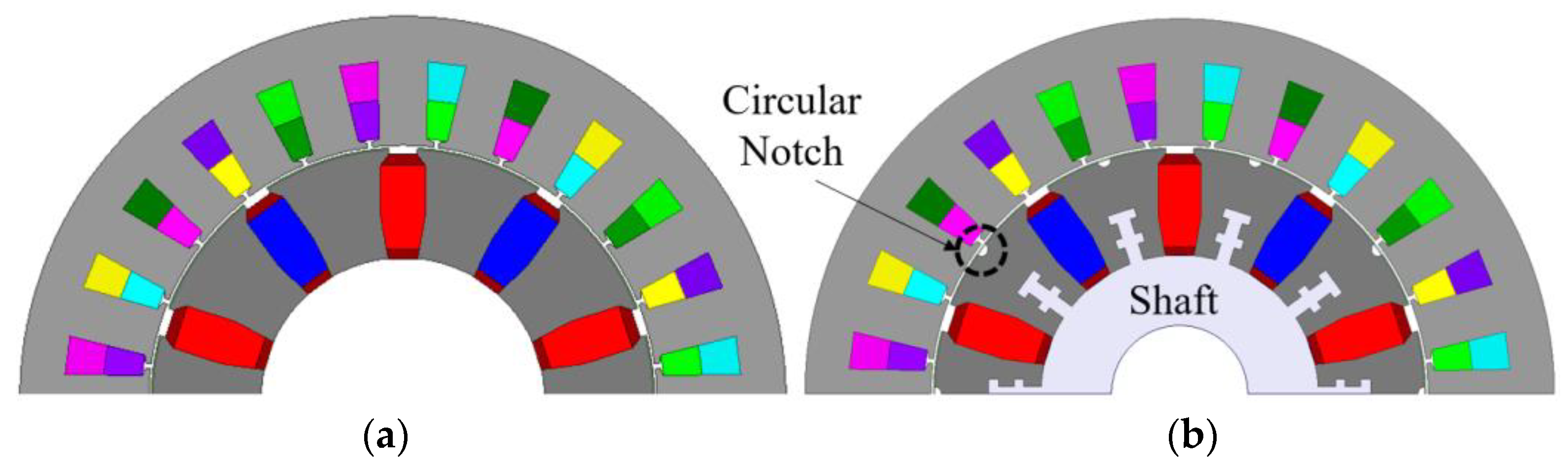
3.1. Torque Ripple Reducing Circular Notch
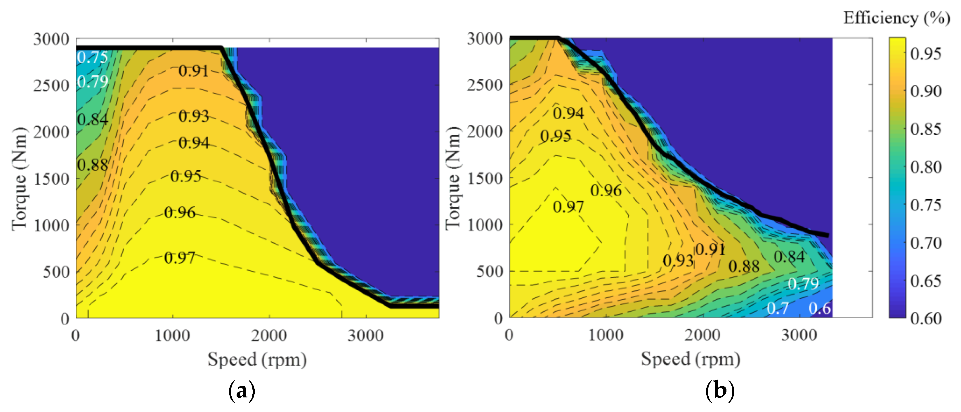
3.2. Efficiency Map
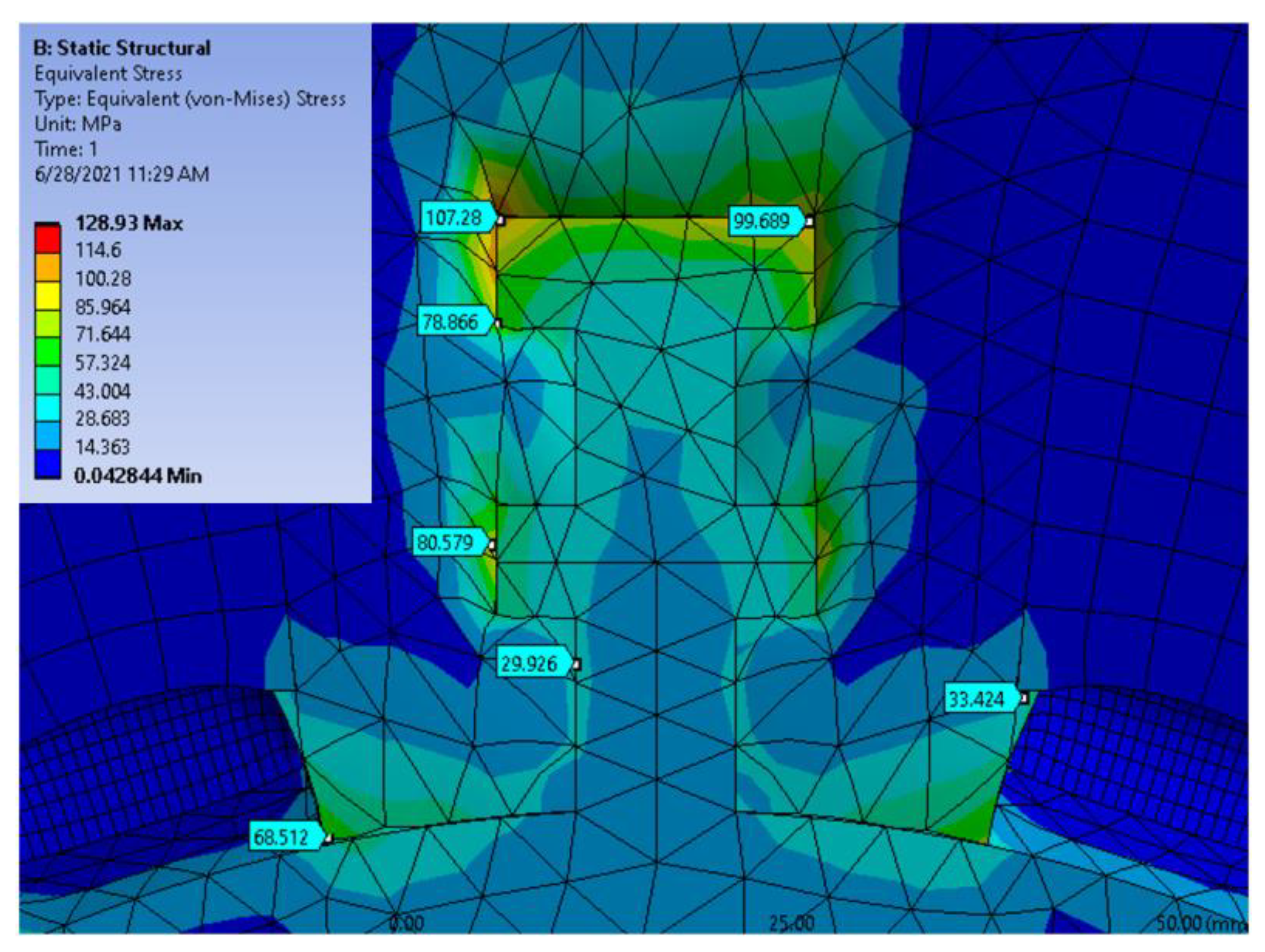
3.3. Mechanical Analysis
3.4. Thermal Analysis
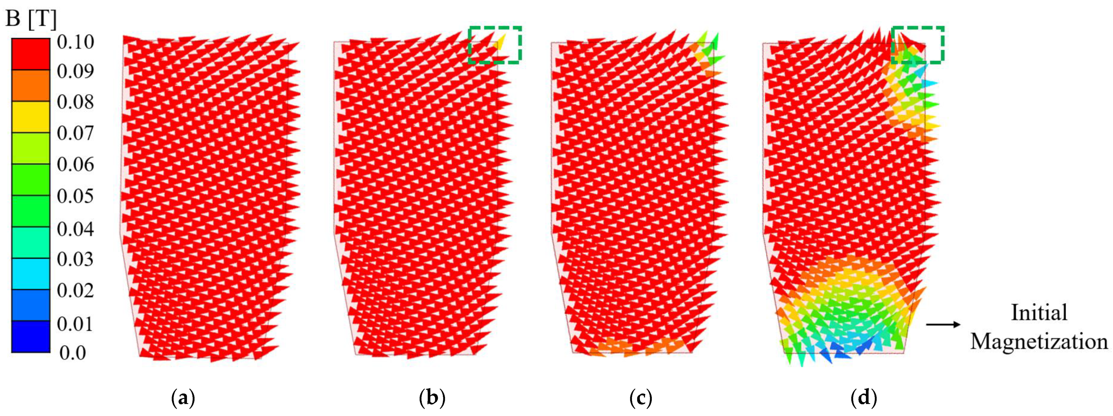
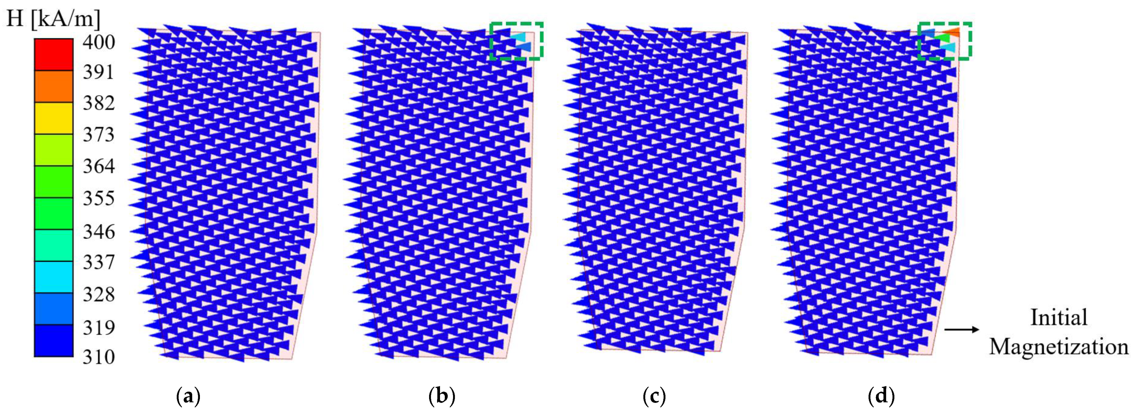
3.5. Demagnetization Analysis
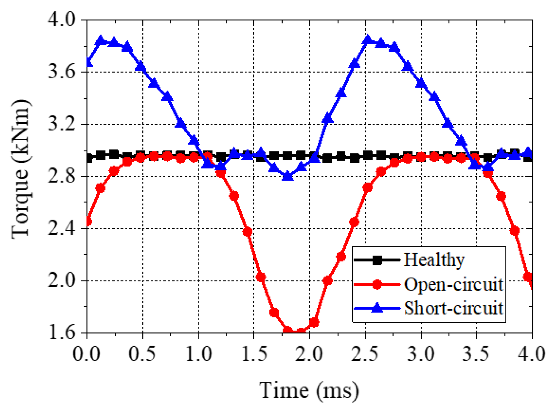
3.6. Fault-Tolerant Capability
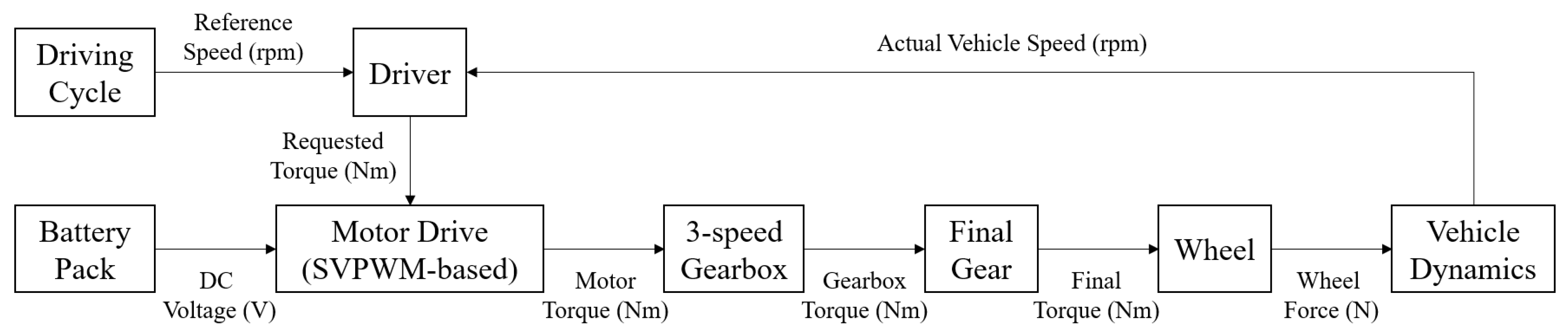
4. Electric Truck Simulation Model
4.1. Driver
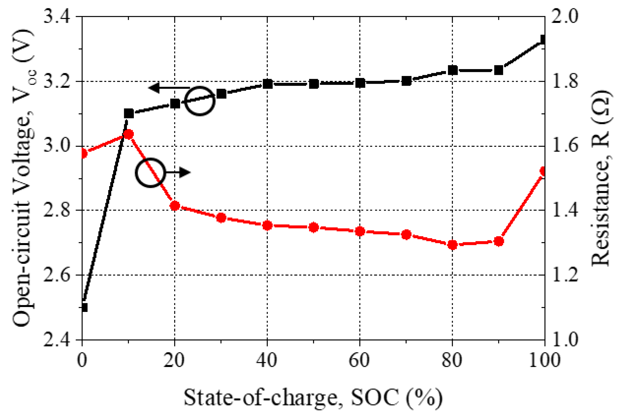
4.2. Battery Pack
4.3. Motor Drive
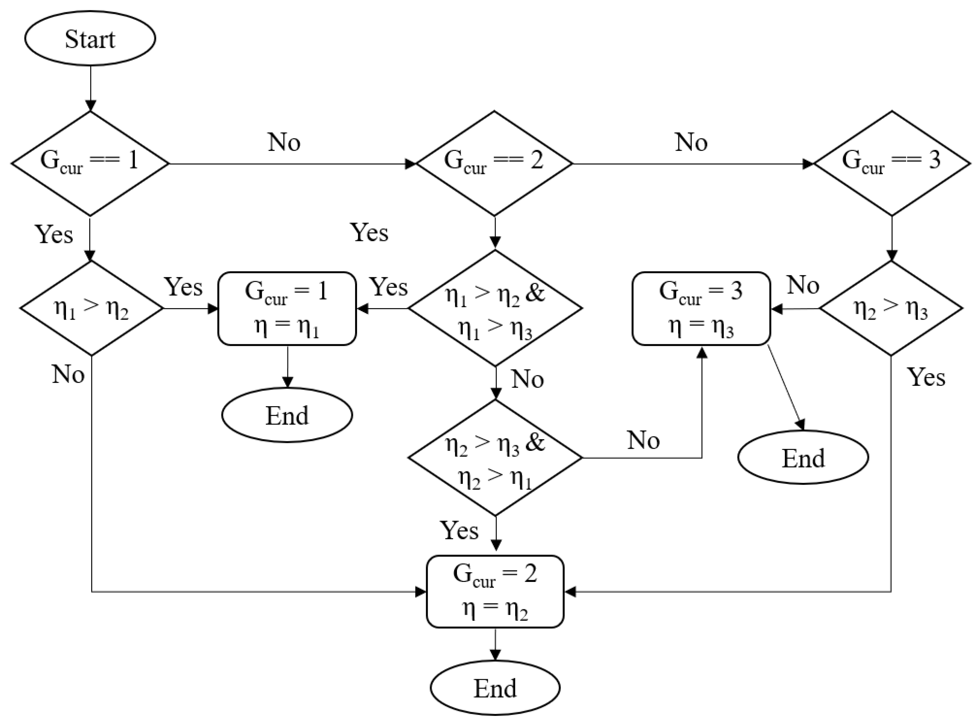
4.4. 3-Speed Gearbox and Final Gear
4.5. Wheel
4.6. Vehicle Dynamics
5. Performance Evaluation of Proposed Motor in Electric Truck Simulation
5.1. Traction Performance
5.2. Energy Consumption
5.3. Cost
6. Conclusions
7. Patents
Author Contributions
Funding
Institutional Review Board Statement
Informed Consent Statement
Data Availability Statement
Conflicts of Interest
References
- Smith, D.; Graves, R.; Ozpineci, B.; Jones, T.; Lustbader, J.; Kelly, K.; Walkowicz, K.; Birky, A.; Payne, G.; Sigler, C.; et al. Medium- and Heavy-Duty Vehicle Electrification An Assessment of Technology and Knowledge Gaps; ORNL/SPR-2020/7; Oak Ridge National Lab.(ORNL): Oak Ridge, TN, USA, 2019; pp. 1–60.
- U.S. PIRG Education Fund, Environment America Research and Policy Center, Frontier Group. Available online: https://environmentamerica.org/feature/ame/electric-buses-america (accessed on 22 August 2021).
- Morozov, A.; Humphries, K.; Zou, T.; Rahman, T.; Angeles, J. Design, analysis and optimization of a multi-speed powertrain for class-7 electric truck. SAE Int. J. Alt. Power. 2018, 7, 27–42. [Google Scholar] [CrossRef]
- Patel, V.; Wang, J.; Wang, W.; Chen, X. Six-phase fractional-slot-per-pole-per-phase permanent-magnet machines with low space harmonics for electric vehicle application. IEEE Trans. Ind. Appl. 2014, 50, 2554–2563. [Google Scholar] [CrossRef] [Green Version]
- Abdel-Khalik, A.; Ahmed, S.; Massoud, A. A six-phase 24-Slot/10-pole permanent magnet machine with low space harmonics for electric vehicle applications. IEEE Trans. Magn. 2016, 52, 8700110. [Google Scholar] [CrossRef]
- Cheng, L.; Sui, Y.; Zheng, P.; Yin, Z.; Wang, C. Influence of stator MMF harmonics on the utilization of reluctance torque in six-phase PMA-SynRM with FSCW. Energies 2018, 11, 108. [Google Scholar] [CrossRef] [Green Version]
- Bianchi, N.; Bolognani, S.; Pre, M.; Grezzani, G. Design considerations for fractional-slot winding configuration of synchronous machines. IEEE Trans. Ind. Appl. 2006, 42, 907–1006. [Google Scholar] [CrossRef]
- Tangudu, J.; Jahns, T.; El-Refaie, A. Unsaturated and saturated saliency trends in fractional-slot concentrated-winding interior permanent magnet machines. In Proceedings of the IEEE Energy Conversion Congress and Exposition (ECCE), Atlanta, GA, USA, 12–16 September 2010. [Google Scholar]
- Alberti, L.; Bianchi, N. Theory and Design of Fractional-slot Multilayer Windings. IEEE Trans. Ind. Appl. 2013, 49, 841–849. [Google Scholar] [CrossRef]
- Dajaku, G.; Gerling, D. Eddy current loss minimization in rotor magnets of PM machines using high-efficiency 12-teeth/10-slots winding topology. In Proceedings of the 2011 International Conference on Electrical Machines and Systems, Beijing, China, 20–23 August 2011. [Google Scholar]
- Dajaku, G. Elektrische Maschine. German Patent DE 102008 057349 B3, 15 July 2010. [Google Scholar]
- Jeong, C.; Hur, J. A novel proposal to improve reliability of spoke-type BLDC motor using ferrite permanent magnet. IEEE Trans. Ind. Appl. 2016, 52, 3814–3821. [Google Scholar] [CrossRef]
- Won, H.; Hong, Y.; Choi, M.; Bryant, B.; Platt, J.; Choi, S. Cost-effectiveness hybrid permanent magnet assisted synchronous reluctance machine for electric vehicle. In Proceedings of the IEEE International Electric Machines and Drives Conference, Online, 17–20 May 2021. [Google Scholar]
- Ma, Q.; ElRefaie, A.; Lequesne, B. Low-cost interior permanent magnet machine with multiple magnet types. IEEE Trans. Ind. Appl. 2020, 56, 1452–1463. [Google Scholar] [CrossRef]
- Kimiabeigi, M.; Widmer, J.; Long, R.; Gao, Y.; Goss, J.; Martin, R.; Lisle, T.; Soler Vizan, J.; Michaelides, A.; Mecrow, B. On selection of rotor support material for a ferrite magnet spoke-type traction motor. IEEE Trans. Ind. Appl. 2016, 52, 2224–2233. [Google Scholar] [CrossRef] [Green Version]
- Zhao, W.; Lipo, T.; Kwon, B. Torque pulsation minimizations in spoke-type interior permanent magnet motors with skewing and sinusoidal permanent magnet configurations. IEEE Trans. Magn. 2015, 51, 1–6. [Google Scholar]
- Won, H.; Hong, Y.; Platt, J.; Choi, M.; Bryant, B.; Choi, S. Six-phase fractional-slot concentrated winding ferrite spoke-type permanent magnet synchronous motor for electric truck. In Proceedings of the IEEE International Electric Machines and Drives Conference, Online, 17–20 May 2021. [Google Scholar]
- N42UH Arnold Magnetic Technologies. Available online: http://www.arnoldmagnetics.com/wp-content/uploads/2017/11/N42UH-151021.pdf (accessed on 23 February 2022).
- El-Refaie, A.; Alexander, J.; Galioto, S.; Reddy, P.; Huh, K.; Bock, P.; Shen, X. Advanced high-power density interior permanent magnet motor for traction applications. IEEE Trans. Ind. Appl. 2014, 50, 3235–3248. [Google Scholar] [CrossRef]
- Abdel-Khalik, A.; Ahmed, S.; Massoud, A. Low space harmonics cancellation in double layer fractional slot winding using dual multi-phase winding. IEEE Trans. Magn. 2015, 51, 8104710. [Google Scholar] [CrossRef]
- Rashid, M. Power Electronics: Circuits, Devices and Applications, 3rd ed.; Prentice Hall: London, UK, 2004; pp. 919–923. [Google Scholar]
- Li, Y.; Li, C.; Garg, A.; Gao, L.; Li, W. Heat dissipation analysis and multi-objective optimization of a permanent magnet synchronous motor using surrogate assisted method. Case Stud. Therm. Eng. 2021, 27, 101203. [Google Scholar] [CrossRef]
- Ferrite Summary, TDK. Available online: https://product.tdk.com/en/system/files?file=dam/doc/product/ferrite/ferrite/ferrite-core/catalog/ferrite_summary_en.pdc (accessed on 23 February 2022).
- Permanent Magnets, Hitachi. Available online: https://www.hitachimetals.com/materials-products/permanent-magnets/documents/Permanent_Magnets.pdf (accessed on 23 February 2022).
- Zou, Z.; Davis, S.; Beaty, K.; O’Keefe, M.; Hendricks, T.; Rehn, R.; Weissner, S.; Sharma, V. A new composite drive cycle for heavy-duty hybrid electric class 4–6 vehicles. SAE Trans. J. Eng. 2004, 113, 771–778. [Google Scholar]
- Green Car Reports. Available online: https://www.greencarreports.com/news/1132072_report-60-kwh-battery-pack-price-will-make-evs-cheaper-than-combustion (accessed on 22 August 2021).


| Parameter | Value |
|---|---|
| Stator outer/inner diameter [mm] | 550/366 |
| Rotor outer/inner diameter [mm] | 362/196 |
| Stack length [mm] | 300 |
| Number of slots/poles | 12/10 |
| Number of turns | 64 |
| Number of parallel paths | 8 |
| Rated/peak current density [A/m2] | 6.3/16.4 |
| Rated/peak current [Arms] | 250/636 |
| Copper mass [kg] | 135 |
| Maximum torque [Nm] | 3110 |
| Soft iron core material | M19–29G |
| Parameter | Conventional | Proposed |
|---|---|---|
| Stator outer/inner diameter [mm] | 550/366 | |
| Rotor outer/inner diameter [mm] | 362/196 | |
| Stack length [mm] | 300 | |
| Number of slots/poles | 12/10 | 24/10 |
| Number of turns | 64 | 32 |
| Number of parallel paths | 8 | 8 |
| Coil pitch | 1 | 2 |
| Rated/peak current density [A/m2] | 6.3/16.4 | |
| Rated/peak current [Arms] | 250/636 | |
| Parameter | Conventional | Proposed |
|---|---|---|
| Maximum torque [Nm] | 2320 | 2970 |
| Torque ripple (Trip) [%] | 10.9 | 2.5 |
| Cogging torque (Tcog) [Nm] | 3.3 | 3.3 |
| Total harmonic distortion (THD) of back-EMF at 2000 rpm [%] | 37.3 | 33.1 |
| Parameter | No Notch | Circular Notch on Rotor | Notch with Shaft |
|---|---|---|---|
| Torque [Nm] | 2970 | 2980 | 2980 |
| Torque ripple [%] | 2.5 | 1.2 | 1.2 |
| Torque ripple difference from no circular void [%] | - | 53 | 53 |
| Parameter | Symbol | Value [mm] |
| Stator | ||
| Yoke height | Hy | 32 |
| Upper slot width | Wsu | 27.5 |
| Bottom slot width | Wsb | 15 |
| Slot height | Hs | 55 |
| Tooth width | Wt | 36 |
| Slot opening height | Hso | 3.3 |
| Slot opening width | Wso | 3.3 |
| Outer stator radius | Rso | 275 |
| Inner stator radius | Rsi | 183 |
| Rotor | ||
| Rotor opening height | Hro | 12.1 |
| Rotor opening width | Wro | 20.5 |
| Rectangular cavity 1 height | Hw1 | 7.3 |
| Rectangular cavity 2 height | Hw2 | 11.4 |
| Rectangular cavity 3 height | Hw3 | 12.6 |
| Rectangular cavity 1 width | Ww1 | 20.8 |
| Rectangular cavity 2 width | Ww2 | 10.4 |
| Circular notch rotor | Rcir | 5.5 |
| Outer rotor radius | Rro | 181 |
| Inner rotor radius | Rri | 98 |
| Permanent Magnet | ||
| Upper permanent magnet width | Wu_pm | 31.7 |
| Bottom permanent magnet width | Wb_pm | 23.3 |
| Upper permanent magnet height | Hu_pm | 37.1 |
| Bottom permanent magnet height | Hb_pm | 23.8 |
| Component | Thermal Conductivity [W/(mK)] | Material |
|---|---|---|
| Stator/Rotor | 48 | Silicon steel |
| Shaft | 105 | CuBe alloy |
| Winding | 387.6 | Copper |
| Air gap | 0.429 | Air |
| Permanent magnet | 1 | Ferrite |
| Rotor wedges | 0.1 | Non-metallic composite |
| Component | Power Loss Density [W/m3] |
|---|---|
| Stator | 1,111,863 |
| Rotor | 83,169.6 |
| Winding | 1,744,287.42 |
| Magnetic Property | −40 °C | 80 °C |
|---|---|---|
| Remanent flux density (Br) [T] | 0.51 | 0.38 |
| Coercivity (Hc) [kA/m] | 345 | 299 |
| Intrinsic Coercivity (Hci) [kA/m] | 350 | 414 |
| Parameter | Symbol | Value |
|---|---|---|
| Vehicle mass [kg] | mveh | 15,227 |
| Dynamic wheel radius [m] | Rwheel | 0.488 |
| Rolling resistance coefficient | Crr | 0.008 |
| Coefficient of aerodynamic drag | Cd | 0.6 |
| Vehicle frontal area [m2] | Av | 9.0 |
| Initial State-of-Charge [%] | SOCinit | 100 |
| Number of battery cell in parallel/series | Nparallel/Nseries | 53/225 |
| Final drive gear ratio | GFDR | 7.17 |
| Drive Cycle | 1st | 2nd | 3rd |
|---|---|---|---|
| CILCC | 1.01 | 0.539 | 0.241 |
| OCC | 1.16 | 0.584 | 0.302 |
| UDDSHDV | 1.09 | 0.489 | 0.302 |
| HWFET | 1.01 | 0.416 | 0.259 |
| Drive Cycle | Energy Consumption in Wh | Energy Consumption in Wh/km | Consumption Savings [%] | ||
|---|---|---|---|---|---|
| Reported 6Φ-FSCW-Nd-FIPMSM | Proposed 6Φ-SS-FSCW-Fer-SIPMSM | Reported 6Φ-FSCW-Nd-FIPMSM | Proposed 6Φ-SS-FSCW-Fer-SIPMSM | ||
| CILCC | 8485.7 | 8430.7 | 441.1 | 438.3 | 0.64 |
| OCC | 4719.6 | 4692.0 | 452.1 | 449.4 | 0.60 |
| UDDSHDV | 5658.0 | 5583.6 | 451.6 | 445.6 | 1.33 |
| HWFET | 452.0 | 446.5 | 452.0 | 446.5 | 1.22 |
| Material | Cost ($/kg) | Density (g/cm3) |
|---|---|---|
| NdFeB | 100 | 7.5 |
| Ferrite | 7 | 5 |
| Copper | 7.03 | 8.96 |
| CuBe alloy | 165 | 1 |
| M19–29G | 1.0 | 7.85 |
| Part | Reported | Proposed | Cost Savings [%] | ||||
|---|---|---|---|---|---|---|---|
| Volume [cm3] | Weight [kg] | Cost [$] | Volume [cm3] | Weight [kg] | Cost [$] | ||
| Stator | 31,105 | 244.1 | 244 | 31,261 | 245.4 | 245 | 0 |
| Rotor | 19,819 | 155.6 | 156 | 14,234 | 111.8 | 112 | 28 |
| Magnet | 3570 | 26.8 | 2677 | 5467 | 27.4 | 191 | 92.9 |
| Coil | 15,066 | 135 | 949 | 15,066 | 135 | 949 | 0 |
| Wedges | 0 | 0 | 0 | 100.5 | 0.15 | 16.6 | −16,600 |
| Total | 561 | 4026 | 519 | 1514 | 62.4 | ||
Publisher’s Note: MDPI stays neutral with regard to jurisdictional claims in published maps and institutional affiliations. |
© 2022 by the authors. Licensee MDPI, Basel, Switzerland. This article is an open access article distributed under the terms and conditions of the Creative Commons Attribution (CC BY) license (https://creativecommons.org/licenses/by/4.0/).
Share and Cite
Won, H.; Hong, Y.-K.; Choi, M.; Platt, J.; Bryant, B.; Choi, S.; Li, S.; Yoon, H.-S.; Haskew, T.A.; Lee, J.; et al. Novel Design of Six-Phase Spoke-Type Ferrite Permanent Magnet Motor for Electric Truck Application. Energies 2022, 15, 1997. https://doi.org/10.3390/en15061997
Won H, Hong Y-K, Choi M, Platt J, Bryant B, Choi S, Li S, Yoon H-S, Haskew TA, Lee J, et al. Novel Design of Six-Phase Spoke-Type Ferrite Permanent Magnet Motor for Electric Truck Application. Energies. 2022; 15(6):1997. https://doi.org/10.3390/en15061997
Chicago/Turabian StyleWon, Hoyun, Yang-Ki Hong, Minyeong Choi, Jonathan Platt, Briana Bryant, Seungdeog Choi, Shuhui Li, Hwan-Sik Yoon, Timothy A. Haskew, Jongkook Lee, and et al. 2022. "Novel Design of Six-Phase Spoke-Type Ferrite Permanent Magnet Motor for Electric Truck Application" Energies 15, no. 6: 1997. https://doi.org/10.3390/en15061997