
Prediction of Wall and Indoor Hygrothermal Properties of Rammed Earth Folk House in Northwest Sichuan


1
College of Architecture and Environment, Sichuan University, Chengdu 610065, China
2
School of Civil Engineering and Architecture, Southwest University of Science and Technology, Mianyang 621010, China
*
Author to whom correspondence should be addressed.
Energies 2022, 15(5), 1936; https://doi.org/10.3390/en15051936
Submission received: 28 January 2022
/
Revised: 1 March 2022
/
Accepted: 3 March 2022
/
Published: 7 March 2022
(This article belongs to the Special Issue Green Buildings for Carbon Neutral)
Abstract
:The climate crisis is one of the most important problems today. In the process of human building, the use of cement, steel, and other industrial materials in the process of building construction and recycling has brought a huge burden to the natural environment. Earth is one of the oldest building materials, its availability and insulation make it an excellent constructive solution in human history. Among several existing earth construction techniques, rammed earth is one of the most relevant. In this paper, a numerical model of the rammed earth folk house in Mianyang was established, and an experimental device was built to verify it. With the typical meteorological year data of Mianyang in northwest Sichuan, the heat and moisture transfer in rammed earth wall, as well as the indoor thermal and moisture environment were numerically simulated. The results show that the rammed earth wall weakens the temperature fluctuation of the inner surface of the wall and makes the peak temperature of the inner surface of the wall lag the outer surface. The relative humidity in the center of the rammed earth wall can be maintained at about 60%, both in winter and summer. The moisture absorption and desorption capacity of rammed earth walls without inner decorative materials is about three times that of gypsum board, and the use of a waterproof coating will render the rammed earth wall almost unable to adjust the indoor relative humidity. Additionally, the use of decorative materials will increase the fluctuation range of indoor relative humidity and the risk of mold breeding.
1. Introduction
The 75th UN General Assembly held in September 2020 proposed that the climate crisis is one of the most important problems today. Although the greenhouse gas emissions decreased in 2020 due to the COVID-19 pandemic, the pandemic prompted us to re-examine our relationship with the natural environment. In the process of human building, cement, steel and other industrial materials used in the process of construction and recycling are responsible for 33% of the emissions, 40% of the material consumption and 40% of all waste [1], which has brought a huge burden to the natural environment. Therefore, it is a duty and a necessity to focus on the use of materials suitable for sustainability.
Earth is one of the oldest building materials. It is estimated that 40% of the world’s population lives in earthen buildings [2]. Its availability and insulating properties have turned it into an excellent constructive solution throughout human history. At the end of its life, the earth can be easily recycled to produce new products, or it can be disaggregated and returned to the natural environment with a negligible environmental impact [3].
Among several existing earth construction techniques, rammed earth is one of the most relevant. Rammed earth has been used in many countries around the world since ancient times [4,5]. In recent years, due to the high attention paid to the environmental sustainability of building materials, rammed earth has received a new impetus [6,7,8]. In the past decades, many countries such as France, Spain, Australia, New Mexico, and Peru have formulated the construction standards of rammed earth buildings, but these standards often pay too much attention to the structural strength and durability of buildings [9,10,11] and ignore the thermal performance of envelope structures [12]. Rammed earth has a good capacity to reduce the thermal amplitude inside the building [13], as well as the characteristics of moisture absorption and release. Recent research shows that the reduction in thermal amplitude provided by rammed earth is between 70% and 77% with the wall thickness of 290 mm and up to 75% to 80% with the wall thickness of 500 mm [14,15]. The thermal conductivity of rammed earth is 0.60 W/mK, which is a key performance parameter of rammed earth. The thermal conductivity of air is 0.025 W/mK, and that of water is 0.60 W/mK [16]. This shows that the thermal conductivity of water is better than that of air. Results show that the thermal conductivity of saturated rammed earth is twice that of dry rammed earth [17], and even 2–2.4 times [18].
Humidity regulation is another feature of rammed earth walls. With the change of relative humidity, rammed earth walls can absorb and release water vapor from the air to help adjust the stable indoor humidity environment [19,20]. The interior of the rammed earth wall is a porous material, and the internal space is filled with multiphase materials. At least one phase material is non-solid, which can be gaseous or liquid. The internal heat and moisture transfer problem is a complex nonlinear process including the diffusion transfer and mutual transformation of gas phase and liquid phase [21]. Water can transfer to the surrounding environment through moisture absorption/dehumidification. The change of moisture content in the material will directly change the thermal conductivity and specific heat capacity of the material [22], and the resulting changes in thermal conductivity and specific heat capacity have been reported [23,24]. However, studies have also shown that although rammed earth wall can improve the indoor thermal and humid environment in summer, it cannot maintain a more comfortable living environment in winter [25], so it is necessary to set an additional heating equipment.
The moisture transfer of the building envelope is important to the calculation of building cooling and heating load. At present, the influence of moisture absorption and desorption on the inner surface of the building envelope is often ignored in the calculation of building cooling and heating load [26], resulting in the inaccuracy of building cooling and heating load calculation. For example, when calculating the cooling load of the multi-stored brick concrete wall, whether to consider the moisture transfer of the wall will cause a deviation of 11.3% [27].
At present, most building energy-consumption calculation software, such as DOE-2, Energy plus, TRNSYS, ESP-r, BSim, and Clim2000, mostly focus on dynamic heat transfer calculation [28] but pay less attention to moisture transfer. In the process of studying the coupled heat and moisture transfer, researchers have developed various simulation tools to simulate the heat and moisture distribution by using different driving potentials and simplified assumptions. MOIST takes temperature and moisture capacity as the driving potential and considers the discontinuity of moisture content at the boundary of different hygroscopic materials [29], so as to solve the heat and moisture transfer of composite walls under non-isothermal conditions. HygIRC considers both air and water penetration inside building materials and the influence of gravity on capillary transmission. The model is also used to analyze the wet characteristics of building components [30]. UMIDUS considers vapor diffusion and capillary flow of liquid water, which can be used to calculate the coupled heat and moisture transfer in porous media. WUFI can calculate the transient thermal and moisture characteristics of multi-story building materials under natural meteorological conditions [31]. MOIST, HygIRC, UMIDUS, and WUFI have the same governing equations for calculating the heat and moisture transfer inside the building envelope. Their differences lie in the setting of surface boundary conditions, material properties, and numerical calculation methods. HygIRC, UMIDUS, and WUFI all consider the capillary transmission of liquid water and can deal with the wet surface conditions caused by rainwater. UMIDUS can conduct the overall building thermal and moisture analysis, but it ignores the transmission of liquid water.
Five major climatic zones for building design were identified in China’s national climate classification (Figure 1). Mianyang is located in the northwest of Sichuan, with a hot summer and cold winter climate. The average temperature of the coldest month in the region is between 0 and 10 °C, and the average temperature of the hottest month is between 25 and 30 °C [32]. For a rammed earth folk house in Mianyang, a numerical model was established, and an experimental device was built to verify it in this paper. With the typical meteorological year data of Mianyang in northwest Sichuan Province, the heat and moisture transfer in rammed earth wall, as well as the indoor thermal and moisture environment were numerically simulated. The results provide a reference for the construction of a good thermal and moisture environment of rammed earth folk house.
2. Mathematical Models
To study the heat and moisture transfer in rammed earth walls, as well as the indoor thermal and moisture environment of the rammed earth folk house, a mathematical model coupled with the indoor air balance of the folk house was established.
2.1. Hygrothermal Model of the Rammed Earth Wall
As a porous building material with excellent hygroscopic performance, heat and moisture transfer in the rammed earth wall is a complex and unsteady process. The rammed earth is regarded as an isotropic porous material in this study. The influence of gravity on moisture transfer is neglected. Water vapor is regarded as an ideal gas. The moisture component in the rammed earth is considered as a gas–liquid two-phase flow. The moisture transfer inside the wall includes water vapor and liquid water, which follows Fick’s law. Correspondingly, the internal energy change is represented by the enthalpy change of the solid matrix, water vapor and liquid water in the unit. Specific expressions of the equation can be found in Ref. [34].
In the simulation calculation, the convective heat transfer coefficient on the internal and external surfaces of the wall can be taken in the range of 1–25 W/m2K [35]. The convective heat transfer coefficient on the internal and external surfaces of the rammed earth wall was set as 8.72 W/m2K and 23.26 W/m2K [36], respectively. The moisture exchange coefficient can be determined by the Lewis Relationship [37], the value was 7.7 × 10⁻⁹ h. The water vapor permeability of the rammed earth was set to 1.20 × 10⁻¹¹, the thermal conductivity was set to 0.657 W/mK, the rammed earth wall density was set to 2160 kg/m3 [34].
2.2. Heat and Moisture Balance of Indoor Air
2.2.1. Heat Balance of Indoor Air
The indoor temperature distribution of rammed earth folk houses is related to time and space. It is assumed that the indoor temperature distribution is uniform. The spatial distribution of indoor temperature is ignored, and only the change of temperature with time is considered.
Considering the heat exchange caused by indoor ventilation, the convective heat exchange between the inner surface of the wall and the indoor air, the heat dissipation of indoor equipment and personnel, the solar radiation that enters the room through the doors and windows, and the latent heat caused by moisture absorption and discharge, the thermal balance equation of indoor air in rammed earth folk house can be written as follows:
where the following are defined: ρa (kg/m3) is the density of the air; cp,a (J/kgK) is the specific capacity of the air; V (m3) is the volume of interior space of rammed earth folk house; Ti(t) (K) is the temperature of indoor air at time t; Qc(t) (W) is the convective heat transfer between the indoor air and the inner surface of the rammed earth wall at time t; Qin(t) (W) is the heat release of indoor equipment and personnel at time t; Qv(t) (W) is the amount of heat entering the room through ventilation at time t; Qs(t) (W) is the heat obtained through the doors and windows at time t; QL(t) (W) is the latent heat caused by moisture absorption and dehumidification on the inner surface of the rammed earth wall at time t; hij (W/m2K) is the convective heat transfer coefficient of the j th inner surface; Tsurfij(t) (K) is the temperature of the j th inner surface at time t; N is the ventilation frequency of the room; Te(t) (K) is the temperature of the outdoor air at time t; I(t) (W/m) is the solar radiation intensity shining on the window at time t; τ is the radiation transmission rate of glass; SC is the shading coefficient of the windows; xf is the effective area coefficient of the window; F (m2) is the area of the window; βij (kg/Pam2s) is the mass transfer coefficient of the j th inner surface of the rammed earth building; Psat,i(t) (Pa) is the saturated vapor pressure of indoor air at time t; φi(t) (%) refers to the relative humidity of indoor air at time t; Psat,surfij(t) (Pa) is the saturated vapor pressure of the rammed earth wall at the j th internal surface position at time t; φsurfij(t) (%) refers to the relative humidity at the j th internal surface location at time t; Aj (m2) is the area of the j th inner surface.
2.2.2. Moisture Balance of Indoor Air
Similarly, the spatial distribution of moisture content of air is ignored:
Rammed earth has good moisture–buffering performance. When the water vapor partial pressure of indoor air is higher than that of the inner surface of the wall, the rammed earth wall will release the water stored inside into the indoor air environment and improve the indoor relative humidity. When the water vapor partial pressure of the indoor air is lower than the water vapor partial pressure of the inner surface of the rammed earth wall, the rammed earth wall will absorb vapor from the indoor environment, reduce the humidity of the indoor air, and release the stored moisture to the room when the indoor air humidity is low. Given the above laws, the influence of moisture absorption and desorption of rammed earth walls on indoor thermal and moisture environment must be considered when studying the hygrothermal performance of rammed earth walls and the indoor thermal and moisture environment of a rammed earth folk house.
Considering the moisture exchange caused by ventilation, the moisture exchange between the rammed earth wall inner surface and the indoor air, and the moisture dissipation of indoor equipment and personnel, the moisture balance equation of the indoor air in the rammed earth folk house can be expressed as:
where the following are defined: wi(t) (kg/kg) is the moisture content of indoor air in rammed earth folk house at time t; wV(t) (kg/kg) is the moisture exchange rate caused by ventilation at time t; wL(t) (kg/kg) is the moisture exchange between the inside and outside of the building at time t; win(t) (kg/kg) is the moisture loss capacity of indoor equipment and personnel at time t; we(t) (kg/kg) is the moisture content of outdoor air at time t.
The conversion relationship between air moisture content and relative humidity can be written as:
where B (Pa) is the local atmospheric pressure.
The hygrothermal model established in this section was solved by COMSOL Multiphysics, based on the finite element method.
3. Numerical Validation
3.1. Validation of Wall Temperature and Relative Humidity
3.1.1. Experimental Equipment Setup
An experimental platform is set up to validate the hygrothermal model and investigate the heat and moisture transfer of the rammed earth wall. The dimensions of the rammed earth wall are 0.24 m × 0.12 m × 0.18 m. A climatic box of dimensions 1.2 m × 0.32 m × 0.33 m with a 50 mm extruded polystyrene board (XPS) is constructed. To ensure that there is heat and moisture transfer only on both sides of the wall without insulation, heat insulation and moisture insulation treatment shall be carried out on other surfaces of the wall. Wrap the air barrier film around the wall without heat and moisture transfer, and apply Vaseline on the surface of the air barrier film.
The climatic box is divided into two equal-volume climate chambers by a measured wall. The temperature of the two equal-volume climate chambers is controlled via a thermostatic water bath, which is connected to the copper pipe. The relative humidity was adjusted using the saturated solutions of potassium sulfate (K2SO4) and sodium bromide (NaBr) (as shown in Table 1). The temperature and humidity in the experiment were measured by the HTS 40 L temperature and humidity sensor (accuracy: ±0.3 °C for temperature, ±3% for relative humidity). Two sensors were mounted inside the two climatic chambers to measure the temperature and relative humidity, as shown in Figure 2c. One sensor was installed in the middle of the rammed earth wall. After the construction of the experimental platform, Vaseline was used to seal the joints.
3.1.2. Boundary Conditions and Initial Conditions
After the test wall was made, they were kept at room temperature (25 °C, 70% RH) and their relative humidity was monitored. When the relative humidity was about 70%, the verification experiment was carried out. The tested wall was wrapped with a damp-proof membrane and insulated with an additional layer of XPS, except for the surface facing the two climatic chambers. The temperature of the thermostatic water bath was set to 30 °C and 15 °C inside the left and right sides of the copper pipe, respectively.
3.1.3. Experimental Test Process
To reduce the influence of temperature fluctuation in the laboratory on the measurement results, the laboratory air conditioning equipment placed on the experimental platform shall be kept at constant temperature and continuous operation during the experimental operation. The experimental test period was 14 days. During the experiment, the sensor was kept running continuously, and data were recorded every 5 min. After the experiment, the recorded data are exported and analyzed.
3.1.4. Numerical Simulation Setup and Results
A uniform mesh grid was adopted in the model validation simulation with an element size of 0.01 mm. The time step was set to 5 min. Based on the measurement results, the initial temperature and humidity were set to 25 °C and 70%, respectively. The convective heat transfer coefficient of the surface on the two sides of the wall was set as 8 W/m2K. The drying period of the tested wall was set as approximately one year to ensure the homogenization of the relative humidity distribution.
For the validation, a probe is set in the middle of the wall to measure temperature and humidity. A comparison of simulated and experimental results is presented in Figure 3. In the validation experiment, the temperature and humidity of the left climate chamber were 30 °C and 97% RH, and the temperature and humidity of the right climate chamber were 15 °C and 60% RH. The moisture was transmitted driven by the humidity gradient on both sides. The relative humidity of the wall reached 87% on the 14th day of the experiment. If the experiment continues, the relative humidity in the middle of the wall will slowly rise to a constant value. The maximum and average relative humidity deviations between the simulation and the experiment are 2.9% and 0.34%, respectively. Considering the accuracy of the probe and the heat insulation treatment of the wall, this error is regarded as acceptable. Thus, the experiment and simulation results are in good agreement.
3.2. Validation of Indoor Temperature and Relative Humidity
To verify the accuracy of the mathematical model of indoor thermal and humid environment of rammed earth folk house, the calculation results presented in this paper are compared with the analytical solution in the literature [38]. The physical parameters of wall materials are shown in Table 2. The convective mass transfer coefficient of the surface is 2 × 10⁻⁸ m/s. The initial temperature of indoor and outdoor air and the wall is 20 °C, and the relative humidity of outdoor air is 30%. The initial value of indoor air temperature and humidity is 20 °C and 30%. There is a moisture source with a moisture dissipation capacity of 500 g/h between 9:00 and 17:00.
The comparison of simulated RH with analytical results is shown in Figure 4. The average relative errors between the numerical solution and the analytical solution are 1.24%, which shows that the numerical model is in good agreement with the analytical solution.
4. Discussion
With the typical meteorological year data of Mianyang in northwest Sichuan Province, the heat and moisture transfer in rammed earth wall, as well as the indoor thermal and moisture environment were numerically simulated.
Based on the above mathematical model and typical meteorological year data of Mianyang in northwest Sichuan (Figure 5), the heat and moisture transfer in rammed earth wall, as well as the indoor thermal and moisture environment were numerically simulated. The indoor air temperature is 25 °C and 16 °C in winter and summer, and the indoor air relative humidity is 60%. The initial temperature and humidity of the wall are consistent with the indoor temperature and humidity under the two working conditions. In the calculation, the X-direction points from outdoor to indoor along the wall thickness direction, Tx=l and φx=l are the temperature and humidity at the distance of l mm from the external surface of the rammed earth wall, respectively. The rammed earth materials are from northwest Sichuan. The chemical composition analysis of the soil, based on x-ray fluorescence, is presented in Table 3. The wall thickness is 500 mm.
4.1. Thermal and Moisture Properties of The Rammed Earth Wall
For the sake of brevity, we agree that points A, B, and C are marked at x = 5 mm, x = 250 mm, and x = 495 mm, respectively, along the X-direction.
Figure 6a,b show the temperature distribution of the rammed earth wall in summer and winter. Under the two working conditions, the outer surface of the wall will absorb solar radiation, resulting in the temperature at point A, which is higher than the outdoor air temperature. Compared with the temperature outside the room, the temperature delay time at the center of the wall is about 12 h, and the temperature fluctuation amplitude is 1.2 °C. In summer, compared with the outdoor temperature, the temperature fluctuation at point C has an 8 h time delay. At the same time, the maximum temperature difference between point A and point C is 11.3 °C, which indicates that the rammed earth wall can effectively reduce the outdoor temperature fluctuation and delay the heat release to the indoor. In winter, along the X direction, the temperature at each position gradually increases. There is a 15 h delay between the temperature at point C and point A. The temperature at the inner surface is always lower than the indoor temperature, and the wall will continue to absorb heat from the room.
Figure 7a,b show the relative humidity distribution at each position of the rammed earth wall in summer and winter. Under the two working conditions, the relative humidity of point A is lower than that of the outdoor air, and there is a time delay of about 6 h. The results show that the relative humidity at the center of the wall is always about 60% under the two working conditions. This is due to the low water vapor permeability coefficient and slow moisture transfer rate of the rammed earth wall in this area. The migration and phase transformation of the moisture components mainly occur near the wall surface. The relative humidity of the internal and external surfaces of the wall is mainly affected by the indoor and outdoor temperature and humidity.
Figure 8 shows the total heat flow and latent heat flow through the inner surface of the rammed earth wall under winter and summer conditions. In summer, the heat flux of the inner surface is always negative, which indicates that the wall always releases heat to the indoor. Although the relative humidity at point C is 2% lower than that of the indoor air (as shown in Figure 7a); this is because the temperature at this location is higher than the indoor temperature, the partial pressure of water vapor at this location is higher than that in the room, and the latent heat flow caused by the wall dehumidification will increase the indoor load. In winter, on the contrary, the wall will absorb heat and moisture from the room and increase the heat outflow.
4.2. Indoor Thermal and Humid Environment
To study the influence of moisture absorption and desorption of rammed earth walls on indoor thermal and humid environments, the indoor thermal and humid environments of rammed earth folk houses were simulated. The plan of the rammed earth folk house is shown in Figure 9. The building size is 4 m × 3 m × 2.7 m, and the wall thickness is 500 mm. There is an outer door with a size of 2.05 m × 0.86 m and a single glass fiber-reinforced plastic window with a size of 0.6 m × 0.9 m. The air exchange rate of the room is 1.5 ACH, there is no heat and humidity source in the room, and the air penetrating the room through the gap between the doors and windows is ignored. It is assumed that the floor and roof are treated with waterproof, moisture-proof, and thermal insulation treatment, and the indoor air is evenly mixed. At the same time, the influence of solar radiation in each direction on the wall is considered. The outdoor meteorological parameters are taken from the typical meteorological year data of Mianyang in northwest Sichuan. The initial temperature and humidity of the wall are 6 °C and 80%, and the initial temperature and humidity of indoor air are 6 °C and 70%.
In this paper, three common wall construction methods of rammed earth folk houses in northwest Sichuan are selected to simulate the influence of moisture absorption and desorption of these three wall structures on indoor thermal and humid environments. Case 1: the inner surface of the wall is not covered, and the rammed earth wall directly exchanges heat and moisture with indoor air. Case 2: the interior surface of the wall is interior decoration, and the surface layer is gypsum board. Case 3: the interior surface of the wall is interior decoration, and the surface layer is a waterproof coating.
To overcome the influence of the initial value, the change of indoor thermal and humidity environment and the heat and moisture transfer of rammed earth wall over two years are calculated. The initial time of calculation corresponds to the early morning of 1 March of a typical meteorological year, and the time step is set as 1 h. The results of typical months in the second year are selected for analysis.
The indoor relative humidity changes in different seasons under different working conditions are shown in Figure 10. It can be seen from the figure that in the typical period of four seasons, the fluctuation amplitude of indoor relative humidity corresponding to the rammed earth wall of cases 1, 2, and 3 are 20%, 37.8%, and 40.4%, respectively, which indicates that the rammed earth wall of the case 1 can significantly reduce the fluctuation of indoor relative humidity. Comparing the indoor relative humidity under different working conditions in different seasons, the time of indoor relative humidity exceeding 80% in case 2 and case 3 is much more than that in case 1. When the indoor relative humidity is greater than 80%, the risk of mold breeding is higher. This is disadvantageous for indoor residents, and the indoor relative humidity of case 1 can be stabilized in the comfort zone of 60–80%.
Figure 11 shows the frequency distribution of indoor air relative humidity in one year. It can be seen from the figure that, in case 3, the time when the indoor relative humidity is greater than 80% and the time when the relative humidity is less than 50% are higher than that in case 1 and case 2. Higher relative humidity will increase the risk of mold growth in the room, while lower relative humidity will make human skin dry. The time of indoor air relative humidity in the range of 60–80% under case 1, case 2 and case 3 accounted for 84.9%, 70.4%, and 60.5%, respectively, of the whole year. The longer the time in the range of 60–80% relative humidity, the better the indoor humidity environment. This shows that the use of decorative materials such as gypsum board and a waterproof coating will increase the fluctuation range of indoor relative humidity and the risk of mold breeding, which is not conducive to the comfort of the human body. Therefore, the absorption and desorption of rammed earth walls can improve the indoor wet environment and adjust the indoor relative humidity.
Figure 12 shows the moisture exchange capacity between the rammed earth wall and indoor air in the hottest month and coldest month for one week, and the positive value indicates that the rammed earth wall absorbs moisture from the room. As shown in the figure, the rammed earth wall is alternately absorbing and discharging moisture. The greater the moisture exchange between the wall and the indoor, the smaller the fluctuation range of indoor relative humidity is (as shown in Figure 10). Under case 1, case 2 and case 3, the maximum moisture absorption capacity of the rammed earth wall in summer is 99.73 g/h, 39.47 g/h, and 0.0086 g/h, respectively, and the maximum moisture release capacity is 169.19 g/h, 60.60 g/h, and 0.0038 g/h, respectively. In winter, the maximum moisture absorption was 35.04 g/h, 9.78 g/h, and 0.0027 g/h, respectively, and the maximum moisture release was 91.02 g/h, 25.53 g/h, and 0.0012 g/h, respectively. The moisture absorption and desorption capacity of the rammed earth wall without an inner facing layer are about three times that of the gypsum board, while the use of a waterproof coating can hardly adjust the indoor relative humidity.
As shown in Figure 13a, the indoor air temperature of rammed earth folk house in summer under different working conditions is shown. For non-air-conditioned rooms in summer, lower indoor temperature will bring better indoor thermal comfort. It can be seen from the figure that under the summer working condition, the indoor temperature corresponding to working case 1 is lower than working case 2 and working case 3 between 1 July and 3 July, while in two-thirds of the next 4 days, the indoor temperature is higher than working case 2 and working case 3, and the maximum temperature difference is 0.29 °C and 0.39 °C, respectively. Compared with Figure 12a, the time when the maximum temperature difference occurs is the same as the time when the wall dehumidifies the most, which shows that the indoor dehumidification of the wall in summer will increase the heat transfer into the room, so as to increase the indoor temperature, and the stronger the dehumidification capacity of the wall, the more obvious the effect is.
As shown in Figure 13b, the indoor temperature of case 1 in winter is slightly higher than that of case 2 and case 3, and the maximum temperature difference is 0.15 °C and 0.18 °C, respectively. Compared with Figure 12b, the time when the maximum temperature difference occurs is the same as the time when the wall moisture absorption is the largest. The reason for the above phenomenon is that solar radiation increases the external surface temperature of the wall in winter, and the rammed earth wall will release heat indoors. At this time, the wall will also release moisture indoors, and the latent heat caused by wall dehumidification will be transmitted indoors at the same time, to increase the indoor heat gain.
5. Conclusions
The long-term prediction of the building envelope and its indoor thermal and humid environment of rammed earth folk house in northwest Sichuan is very important for its research, and in this work, a reliable mathematical model is crucial. In this paper, a mathematical model of heat and moisture transfer between rammed earth walls and indoor air was established. The model qualitatively and quantitatively characterizes the relationship between outdoor climate environment (temperature and humidity and solar radiation), rammed earth walls, and indoor air heat and humidity balance. The reliability of the model was verified based on measured data. Based on the typical meteorological year data of Mianyang in northwest Sichuan province, the heat and moisture transfer in rammed earth wall, as well as the indoor thermal and moisture environment of full-size rammed earth folk house was numerically simulated. The results provide a reference for the creation of a thermal and humid environment of the same type of rammed earth folk house.
The thermal inertia of the rammed earth wall has good thermal inertia, which weakens the temperature fluctuation of the inner surface of the wall and makes the peak temperature of the inner surface of the wall lag behind the outer surface. The lag value is 12 h in summer and 15 h in winter. It is critical for creating a comfortable thermal and humid environment. Taking summer as an example, the rammed earth wall postponed the peak time of the inner surface temperature to the late middle of the night. At this time, due to the absence of solar radiation, the indoor temperature dropped to a more comfortable range.
Due to the porous characteristics of a rammed earth wall, the wall itself has a strong moisture storage capacity and can adjust the relative humidity of indoor air. Even in hot summer and cold winter (northwest Sichuan), the relative humidity in the center of the wall can be maintained at about 60%, which helps to keep the indoor environment dry.
Generally speaking, for the sake of aesthetics, gypsum, a waterproof coating and other decorative materials will be used on the inner surface of the building wall. However, the presented results of this paper show that the moisture absorption and desorption capacity of rammed earth walls without inner facing layer is about three times that of gypsum board. The use of a waterproof coating will make the rammed earth wall almost unable to adjust the indoor relative humidity, thereby increasing the fluctuation range of indoor relative humidity and the risk of mold breeding. It should be pointed out that due to capillary moisture absorption, the wall is susceptible to rot and peel within 1 m near the ground. It is necessary to take measures to prevent such damage.
Finally, it should be pointed out that the rammed earth wall constructed by single soil material will shrink and crack with the increase in service life, which shortens the service life of the building. Our next research will focus on the creation of a thermal and humid environment of a renewable and environmentally friendly modified rammed earth folk house.
Author Contributions
Validation, L.L. and T.W.; formal analysis, T.W.; data curation, L.L.; writing—original draft preparation, Q.G. and T.W.; writing—review and editing, Q.G.; supervision, B.J. and Y.Y.; funding acquisition, B.J. All authors have read and agreed to the published version of the manuscript.
Funding
This research was funded by National Natural Science Foundation of China, grant number 52078439.
Institutional Review Board Statement
Not applicable.
Informed Consent Statement
Not applicable.
Data Availability Statement
Data is contained within the article.
Conflicts of Interest
The authors declare no conflict of interest.
References
- Ness, D.A.; Xing, K. Toward a Resource-Efficient Built Environment: A Literature Review and Conceptual Model. J. Ind. Ecol. 2017, 21, 572–592. [Google Scholar] [CrossRef]
- Jannat, N.; Hussien, A.; Abdullah, B.; Cotgrave, A. Application of agro and non-agro waste materials for unfired earth blocks construction: A review. Constr. Build. Mater. 2020, 254, 119346. [Google Scholar] [CrossRef]
- Mateus, R.; Fernandes, J.; Teixeira, E.R. Environmental Life Cycle Analysis of Earthen Building Materials. In Encyclopedia of Renewable and Sustainable Materials; Hashmi, S., Choudhury, I.A., Eds.; Elsevier: Oxford, UK, 2020; pp. 63–68. [Google Scholar]
- Burroughs, S. Recommendations for the Selection, Stabilization, and Compaction of Soil for Rammed Earth Wall Construction. J. Green Build. 2010, 5, 101–114. [Google Scholar] [CrossRef]
- Gandreau, D.; Ensag, C.R.; Delboy, L. UNESCO World Heritage Inventory of Earthen Architecture, 2012; CRATerre: Villefontaine, France; ENSAG: Grenbole, France, 2012. [Google Scholar]
- Giuffrida, G.; Detommaso, M.; Nocera, F.; Caponetto, R. Design Optimisation Strategies for Solid Rammed Earth Walls in Mediterranean Climates. Energies 2021, 14, 325. [Google Scholar] [CrossRef]
- Bui, Q.-B.; Morel, J.-C. Assessing the anisotropy of rammed earth. Constr. Build. Mater. 2009, 23, 3005–3011. [Google Scholar] [CrossRef]
- Beckett, C.T.S.; Cardell-Oliver, R.; Ciancio, D.; Huebner, C. Measured and simulated thermal behaviour in rammed earth houses in a hot-arid climate. Part A: Structural behaviour. J. Build. Eng. 2018, 15, 243–251. [Google Scholar] [CrossRef] [Green Version]
- Kosarimovahhed, M.; Toufigh, V. Sustainable usage of waste materials as stabilizer in rammed earth structures. J. Clean. Prod. 2020, 277, 123279. [Google Scholar] [CrossRef]
- Arrigoni, A.; Pelosato, R.; Dotelli, G.; Beckett, C.T.S.; Ciancio, D. Weathering’s beneficial effect on waste-stabilised rammed earth: A chemical and microstructural investigation. Constr. Build. Mater. 2017, 140, 157–166. [Google Scholar] [CrossRef] [Green Version]
- Abhilash, H.N.; Morel, J.-C.; Champiré, F.; Fabbri, A. A novel experimental study to investigate the interface properties of rammed earth. Constr. Mater. 2020, 1–9. [Google Scholar] [CrossRef]
- Giuffrida, G.; Caponetto, R.; Nocera, F. Hygrothermal Properties of Raw Earth Materials: A Literature Review. Sustainability 2019, 11, 5342. [Google Scholar]
- Fernandes, J.; Mateus, R.; Gervásio, H.; Silva, S.M.; Bragança, L. Passive strategies used in Southern Portugal vernacular rammed earth buildings and their influence in thermal performance. Renew. Energy 2019, 142, 345–363. [Google Scholar] [CrossRef] [Green Version]
- Serrano, S.; Rincón, L.; González, B.; Navarro, A.; Bosch, M.; Cabeza, L.F. Rammed earth walls in Mediterranean climate: Material characterization and thermal behaviour. Int. J. Low Carbon Technol. 2016, 12, 281–288. [Google Scholar] [CrossRef] [Green Version]
- Serrano, S.; de Gracia, A.; Cabeza, L.F. Adaptation of rammed earth to modern construction systems: Comparative study of thermal behavior under summer conditions. Appl. Energy 2016, 175, 180–188. [Google Scholar] [CrossRef] [Green Version]
- Teixeira, E.R.; Machado, G.; Adilson, P., Jr.; Guarnier, C.; Fernandes, J.; Silva, S.M.; Mateus, R. Mechanical and Thermal Performance Characterisation of Compressed Earth Blocks. Energies 2020, 13, 2978. [Google Scholar] [CrossRef]
- Nshimiyimana, P.; Messan, A.; Courard, L. Physico-Mechanical and Hygro-Thermal Properties of Compressed Earth Blocks Stabilized with Industrial and Agro By-Product Binders. Materials 2020, 13, 3769. [Google Scholar] [CrossRef]
- Bogas, J.A.; Silva, M.; Glória Gomes, M. Unstabilized and stabilized compressed earth blocks with partial incorporation of recycled aggregates. Int. J. Archit. Herit. 2019, 13, 569–584. [Google Scholar] [CrossRef]
- Hall, M.; Allinson, D. Analysis of the hygrothermal functional properties of stabilised rammed earth materials. Build. Environ. 2009, 44, 1935–1942. [Google Scholar] [CrossRef] [Green Version]
- Liuzzi, S.; Hall, M.R.; Stefanizzi, P.; Casey, S.P. Hygrothermal behaviour and relative humidity buffering of unfired and hydrated lime-stabilised clay composites in a Mediterranean climate. Build. Environ. 2013, 61, 82–92. [Google Scholar] [CrossRef]
- Soudani, L.; Fabbri, A.; Morel, J.-C.; Woloszyn, M.; Chabriac, P.-A.; Wong, H.; Grillet, A.-C. Assessment of the validity of some common assumptions in hygrothermal modeling of earth based materials. Energy Build. 2016, 116, 498–511. [Google Scholar] [CrossRef]
- Zhang, L.; Yang, L.; Jelle, B.P.; Wang, Y.; Gustavsen, A. Hygrothermal properties of compressed earthen bricks. Constr. Build. Mater. 2018, 162, 576–583. [Google Scholar] [CrossRef]
- Desta, T.Z.; Langmans, J.; Roels, S. Experimental data set for validation of heat, air and moisture transport models of building envelopes. Build. Environ. 2011, 46, 1038–1046. [Google Scholar] [CrossRef]
- Abahri, K.; Belarbi, R.; Trabelsi, A. Contribution to analytical and numerical study of combined heat and moisture transfers in porous building materials. Build. Environ. 2011, 46, 1354–1360. [Google Scholar] [CrossRef]
- Juan, X.; Ziliang, L.; Weijun, G.; Mengsheng, Y.; Menglong, S. The comparative study on the climate adaptability based on indoor physical environment of traditional dwelling in Qinba mountainous areas, China. Energy Build. 2019, 197, 140–155. [Google Scholar] [CrossRef]
- Chandel, S.S.; Sharma, V.; Marwah, B.M. Review of energy efficient features in vernacular architecture for improving indoor thermal comfort conditions. Renew. Sustain. Energy Rev. 2016, 65, 459–477. [Google Scholar] [CrossRef]
- Fang, A.; Chen, Y.; Wu, L. Transient simulation of coupled heat and moisture transfer through multi-layer walls exposed to future climate in the hot and humid southern China area. Sustain. Cities Soc. 2020, 52, 101812. [Google Scholar] [CrossRef]
- Hong, T.; Chou, S.K.; Bong, T.Y. Building simulation: An overview of developments and information sources. Build. Environ. 2000, 35, 347–361. [Google Scholar] [CrossRef]
- Burch, D.M. An analysis of moisture accumulation in walls subjected to hot and humid climates. ASHRAE Trans. 1993, 99, 1013–1022. [Google Scholar]
- Mukhopadhyaya, P.; Kumaran, K.; Reenen, D.V. Vapour Barrier and Moisture Response of Wood-frame Stucco Wall-Results from Hygrothermal Simulation. In Proceedings of the CIB World Building Congress 2004, Toronto, ON, Canada, 2–7 May 2004; pp. 1–10. [Google Scholar]
- Hema, C.M.; Van Moeseke, G.; Evrad, A.; Courard, L.; Messan, A. Vernacular housing practices in Burkina Faso: Representative models of construction in Ouagadougou and walls hygrothermal efficiency. Energy Procedia 2017, 122, 535–540. [Google Scholar] [CrossRef]
- Ministry of Housing and Urban-Rural Development (MOHURD). GB 50176-2016; Code for Thermal Design of Civil Building; MOHURD: Beijing, China, 2016. [Google Scholar]
- Available online: http://bzdt.ch.mnr.gov.cn/index.html (accessed on 5 September 2019).
- Jiang, B.; Wu, T.; Xia, W.J.; Liang, J.H. Hygrothermal performance of rammed earth wall in Tibetan Autonomous Prefecture in Sichuan Province of China. Build. Environ. 2020, 181, 107128. [Google Scholar] [CrossRef]
- Tao, W. Heat Transfer, 5th ed.; Higher Education Press: Beijing, China, 2019. [Google Scholar]
- Li, L.P.; Wu, Z.G.; He, Y.L.; Lauriat, G.; Tao, W.Q. Optimization of the configuration of 290 × 140 × 90 hollow clay bricks with 3-D numerical simulation by finite volume method. Energy Build. 2008, 40, 1790–1798. [Google Scholar] [CrossRef]
- Yan, Z. Dynamic Modelling of the IndoorThermal and Humidity Environment in the Adobe Buildings. Ph.D. Thesis, Xi’an University of Architecture and Technology, Xi’an, China, 2003. [Google Scholar]
- Bednar, T.; Hagentoft, C.E. Analytical solution for moisture buffering effect Validation exercises for simulation tools. In Proceedings of the 7th Nordic Symposium on Building Physics, Reykjavik, Iceland, 13–15 June 2005. [Google Scholar]
Figure 1.
The climate classification for building design in China and the location of Mianyang, Draft Approval No GS (2019)1694 [33].
Figure 1.
The climate classification for building design in China and the location of Mianyang, Draft Approval No GS (2019)1694 [33].
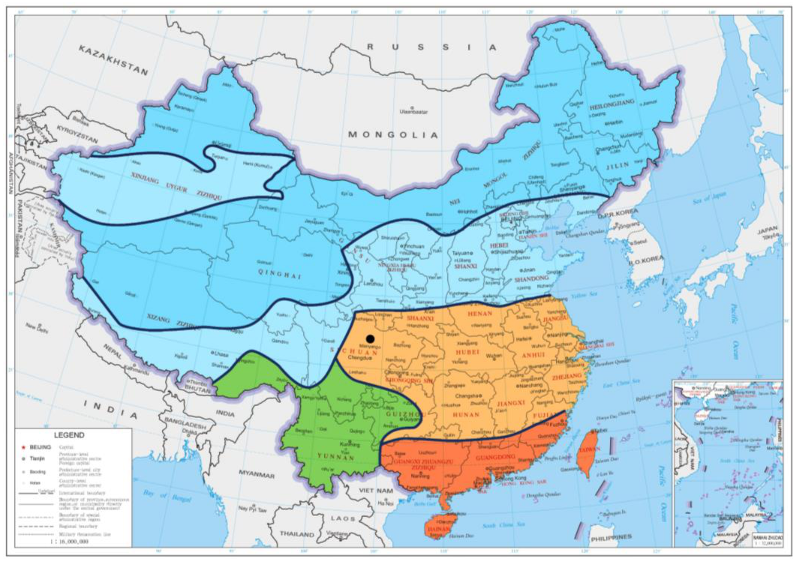
Figure 2.
Experimental equipment for model validation: (a) perspective drawing; (b) experimental equipment system; (c) climate chamber on one side.
Figure 2.
Experimental equipment for model validation: (a) perspective drawing; (b) experimental equipment system; (c) climate chamber on one side.

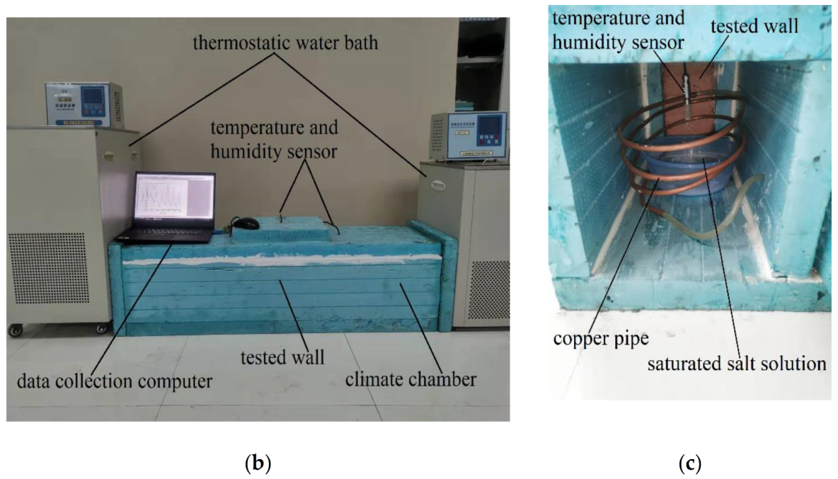
Figure 3.
Comparison of simulated temperature and RH with experimental data.
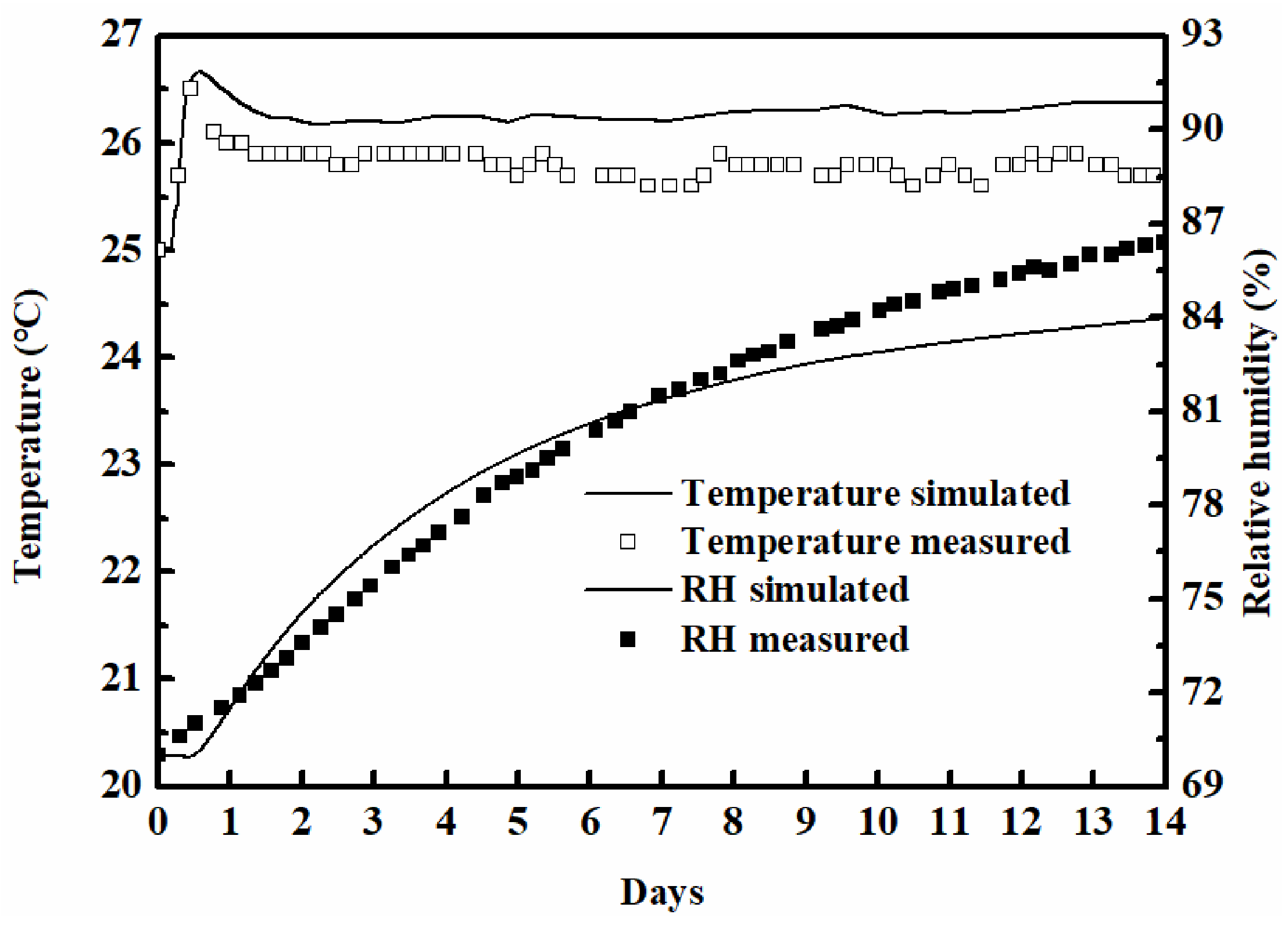
Figure 4.
Comparison of simulated RH with analytical results [38].
Figure 4.
Comparison of simulated RH with analytical results [38].
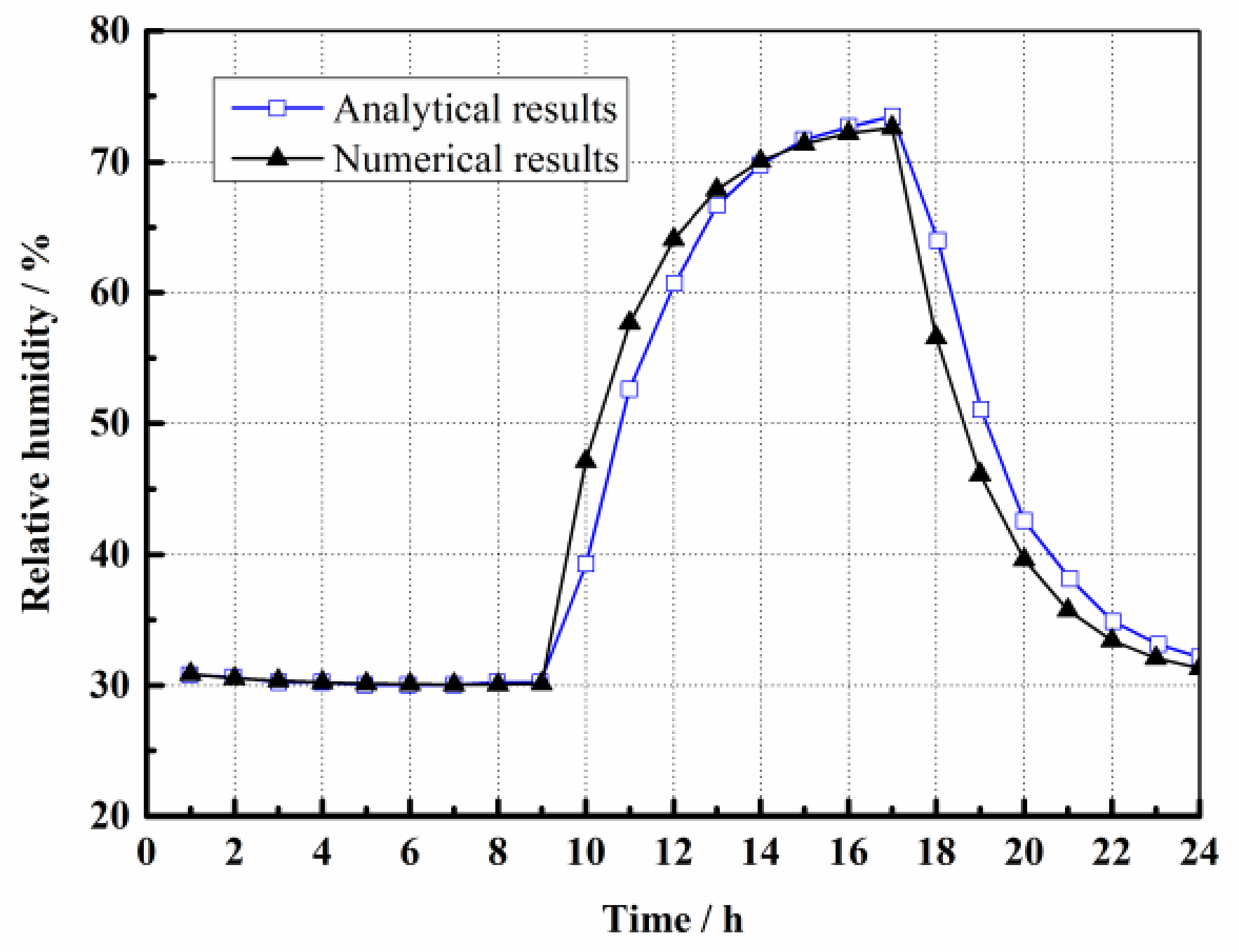
Figure 5.
Outdoor temperature and relative humidity in Mianyang.

Figure 6.
The temperature distribution of the rammed earth wall: (a) the temperature distribution of the rammed earth wall in summer; (b) the temperature distribution of the rammed earth wall in winter.
Figure 6.
The temperature distribution of the rammed earth wall: (a) the temperature distribution of the rammed earth wall in summer; (b) the temperature distribution of the rammed earth wall in winter.

Figure 7.
The relative humidity distribution of the rammed earth wall: (a) the relative humidity distribution of the rammed earth wall in summer; (b) the relative humidity distribution of the rammed earth wall in winter.
Figure 7.
The relative humidity distribution of the rammed earth wall: (a) the relative humidity distribution of the rammed earth wall in summer; (b) the relative humidity distribution of the rammed earth wall in winter.
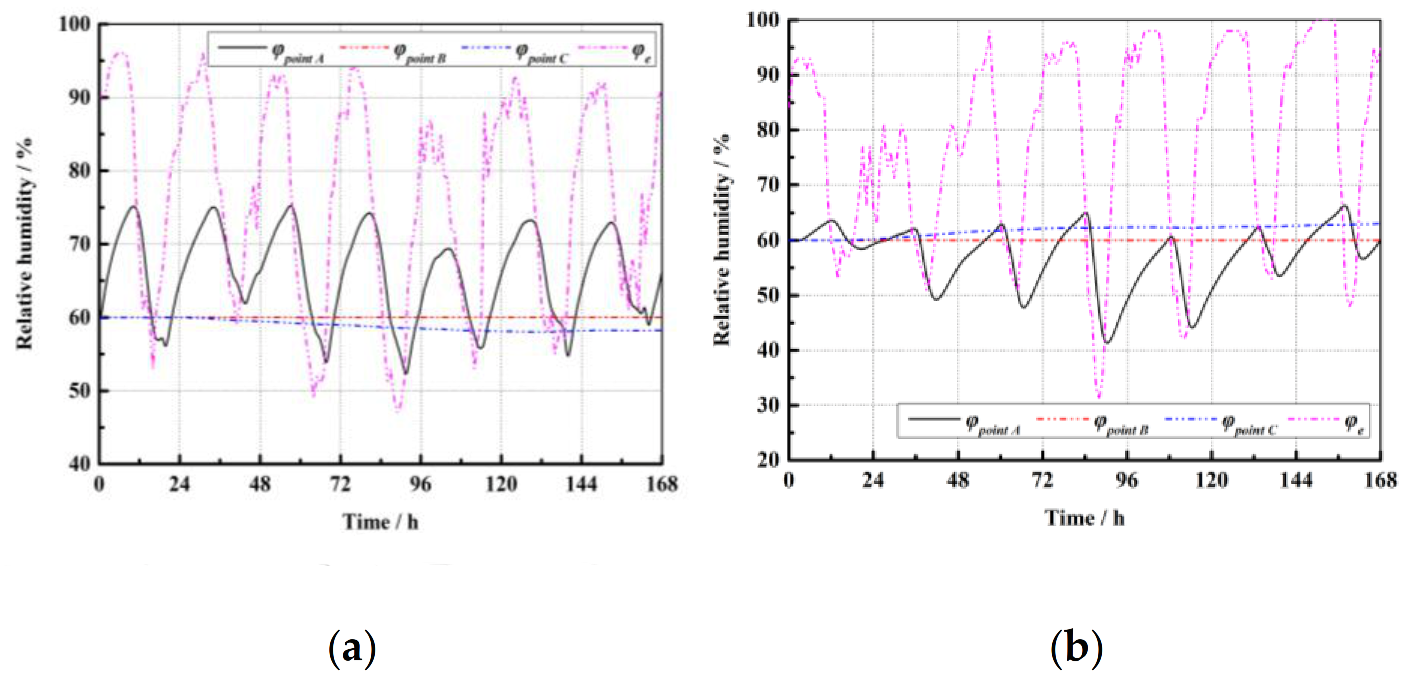
Figure 8.
The heat flux of the internal surface of the rammed earth wall in summer and winter.
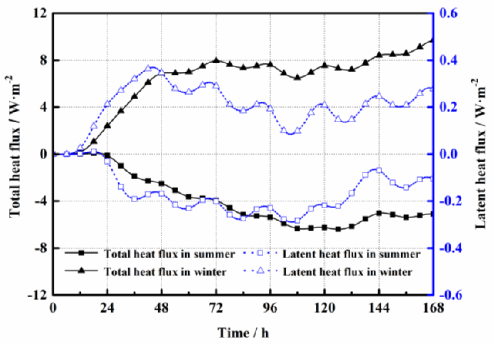
Figure 9.
The drawing of simulated rammed earth folk house: (a) the 3D drawing of simulated rammed earth folk house; (b) plan of the rammed earth folk house.
Figure 9.
The drawing of simulated rammed earth folk house: (a) the 3D drawing of simulated rammed earth folk house; (b) plan of the rammed earth folk house.
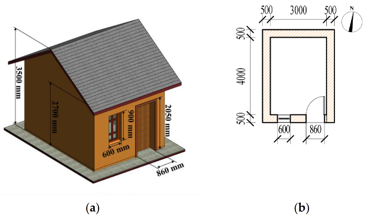
Figure 10.
Indoor relative humidity in each season: (a) in spring; (b) in summer; (c) in autumn; (d) in winter.
Figure 10.
Indoor relative humidity in each season: (a) in spring; (b) in summer; (c) in autumn; (d) in winter.

Figure 11.
Relative humidity distribution of indoor air in one year.

Figure 12.
Moisture exchange on the internal surface of the rammed earth wall: (a) in summer; (b) in winter.
Figure 12.
Moisture exchange on the internal surface of the rammed earth wall: (a) in summer; (b) in winter.

Figure 13.
The indoor air temperature of rammed earth folk house: (a) in summer; (b) in winter.


Table 1.
Saturated salt solutions used for obtaining different relative humidity at 25 °C.
| Molecular Formula | MgCl2 | K2CO3 | NaBr | NaCl | KCl | K2SO4 |
|---|---|---|---|---|---|---|
| Relative humidity | 33.07 ± 0.18 | 43.16 ± 0.33 | 59.14 ± 0.44 | 75.47 ± 0.14 | 85.11 ± 0.29 | 97.59 ± 0.53 |
Table 2.
The physical parameters of wall [38].
Table 2.
The physical parameters of wall [38].
| Physical Parameters | δp/s | ρm/kgm−3 | cp,m/J (kgK)−1 | λ/W (mK)−1 |
|---|---|---|---|---|
| Value | 3 × 10⁻¹¹ | 650.00 | 840.00 | 0.18 |
Table 3.
Chemical composition of rammed earth.
| Name | SiO2 | Al2O3 | CaO | Fe2O3 | K2O | MgO | TiO2 | Na2O | P2O5 | MnO |
|---|---|---|---|---|---|---|---|---|---|---|
| wt.% | 56.52 | 18.39 | 10.23 | 6.70 | 3.72 | 2.46 | 0.90 | 0.54 | 0.17 | 0.11 |
Publisher’s Note: MDPI stays neutral with regard to jurisdictional claims in published maps and institutional affiliations. |
© 2022 by the authors. Licensee MDPI, Basel, Switzerland. This article is an open access article distributed under the terms and conditions of the Creative Commons Attribution (CC BY) license (https://creativecommons.org/licenses/by/4.0/).
Share and Cite
MDPI and ACS Style
Gao, Q.; Wu, T.; Liu, L.; Yao, Y.; Jiang, B. Prediction of Wall and Indoor Hygrothermal Properties of Rammed Earth Folk House in Northwest Sichuan. Energies 2022, 15, 1936. https://doi.org/10.3390/en15051936
AMA Style
Gao Q, Wu T, Liu L, Yao Y, Jiang B. Prediction of Wall and Indoor Hygrothermal Properties of Rammed Earth Folk House in Northwest Sichuan. Energies. 2022; 15(5):1936. https://doi.org/10.3390/en15051936
Chicago/Turabian StyleGao, Qinglong, Tao Wu, Lei Liu, Yong Yao, and Bin Jiang. 2022. "Prediction of Wall and Indoor Hygrothermal Properties of Rammed Earth Folk House in Northwest Sichuan" Energies 15, no. 5: 1936. https://doi.org/10.3390/en15051936
Note that from the first issue of 2016, this journal uses article numbers instead of page numbers. See further details here.