
Energy Saving in Trigeneration Plant for Food Industries †
by
 , , ,
, , ,
Andrii Radchenko
1, 
Mykola Radchenko
1,*,
Dariusz Mikielewicz
2,
Anatoliy Pavlenko
3 ,
,
Roman Radchenko
1 and
Serhiy Forduy
4 1
Machinebuilding Institute, Admiral Makarov National University of Shipbuilding, Heroes of Ukraine Avenue 9, 54025 Mykolayiv, Ukraine
2
Faculty of Mechanical Engineering and Ship Technology, Gdansk University of Technology, 80-233 Gdansk, Poland
3
Department of Building Physics and Renewable Energy, Kielce University of Technology, Al. Thousand Years of Polish State 7, 25-314 Kielce, Poland
4
PepsiCo, Inc., 01010 Kyiv, Ukraine
*
Author to whom correspondence should be addressed.
†
This paper is an extended version of our paper published in 2021 MPSU-2021, E3S Web of Conferences 323, 00029.
Energies 2022, 15(3), 1163; https://doi.org/10.3390/en15031163
Submission received: 7 December 2021
/
Revised: 29 January 2022
/
Accepted: 30 January 2022
/
Published: 4 February 2022
(This article belongs to the Special Issue Computational Thermal, Energy, and Environmental Engineering)
Abstract
:The trigeneration plants for combined cooling, heating, and electricity supply, or integrated energy systems (IES), are mostly based on gas reciprocating engines. The fuel efficiency of gas reciprocating engines depends essentially on air intake temperatures. The transformation of the heat removed from the combustion engines into refrigeration is generally conducted by absorption lithium-bromide chillers (ACh). The peculiarity of refrigeration generation in food technologies is the use of chilled water of about 12 °C instead of 7 °C as the most typical for ACh. This leads to a considerable cooling potential not realized by ACh that could be used for cooling the engine intake air. A refrigerant ejector chiller (ECh) is the simplest in design, cheap, and can be applied as the low-temperature stage of a two-stage absorption-ejector chiller (AECh) to provide engine intake air cooling and increase engine fuel efficiency as result. The monitoring data on gas engine fuel consumption and power were analyzed in order to evaluate the effect of gas engine cyclic air cooling.
1. Introduction
Gas engines (GE) [1,2] are widely applied as drive engines in trigeneration systems, or integrated energy systems (IES), for combined cooling, heating, and power (CCHP) [3,4]. The thermodynamic efficiency of GE falls with increasing inlet air temperature: electric power drops and specific fuel consumption grows. The heat released from GE is mostly converted to refrigeration by absorption lithium-bromide chillers (ACh) and used for technological needs. So it is quite reasonable to use the refrigeration generated by ACh for engine inlet air cooling (EIAC), i.e., for in-cycle trigeneration [5,6]. In addition to enhancing engine fuel efficiency, this enables prolonging the duration of efficient trigeneration plant operation too [7,8]. It is of great importance that the refrigeration demands for technological duties have a periodic character as a rule.
In integrated energy systems for food technologies, chilled water with a temperature of about 12 °C is mostly used; this is higher than the 7 °C characterized for a typical ACh [9,10]. Thus, a significant cooling potential and the corresponding heat released from GE remains and is not realized by ACh. A refrigerant ejector chiller (ECh) might be applied as the low-temperature stage of a two-stage absorption-ejector chiller (AECh) to use the excessive thermal potential for engine intake air cooling that leads to enhanced engine fuel efficiency [11,12].
In a typical IES, all the ambient air coming into the engine room is cooled in the central conditioner [4]. Because of heat influx from the engine room surroundings to the air stream sucked by the engine turbocharger (TC), the temperature of the air at the suction of the turbocharger is increased and the required cooling capacity is enlarged.
Many pieces of research are aimed at enhancing the operational efficiency of trigeneration plants [13,14] based on combustion engines and designed for technological needs [15,16], space conditioning [17,18], and other duties. A lot of them are devoted to improving the fuel efficiency of engines [19,20] through cyclic air cooling in waste heat recovery chillers [21,22]. The ACh is mostly used for chilling air to about 15 °C with a high coefficient of performance (COP) of 0.7 to 0.8 [23,24]. The thermopressors [25,26] and ejector chillers (ECh) [27,28] are the simplest in design, generally consisting of heat exchangers [29,30]. The ejector chillers are able to cool the air down to 10 °C and lower, but with a lowered COP of 0.2 to 0.3.
The efficiency of chillers and cooling systems on the whole can be enhanced by an intensification of heat transfer in evaporators and condensers [31,32] by the application of advanced circulation contours [33,34] using the cooling potential of evaporated water [35,36], exhaust heat potential [37,38], and alternative fuels [39,40]. They enable deep exhaust heat utilization [41,42] with low temperature condensation [43,44]. Such technologies provide for the increasing heat potential to be converted by heat recovery chillers [45,46] for engine cyclic air cooling [47,48]. Many environment-friendly and waste heat conserving innovations might be applied in EIAC [49,50], including transport applications [51,52].
A lot of control optimization [53,54] and regulation [55,56] methods are used to optimize the thermal loads on air cooling systems in order to match actual varying climatic conditions and gain a maximum effect due to cooling. With this, in addition to fundamental exergy and exergoeconomic analysis [57], the widespread methods for estimating the effect gained due to cooling air modified for simplified calculations were developed [58,59,60].
The majority of well-known concepts to enhance the efficiency of trigeneration systems are focused on the engine out-cycle application of refrigeration and based on conventional heat conversion in ACh. A realization of the engine in-cycle concept of trigeneration based on EIAC would provide a widespread application of trigeneration even for the lack of cooling needs.
The application of combined cooling, heat, and power (CCHP) generation, or trigeneration, enables the COP to be increased by about 50% compared with their separate generation and practically twice increased yearly operation time compared with cogeneration; therefore, they are very prosperous in food industries to substitute vapor compression refrigeration with an electrically driven compressor.
The results of similar studies previously published issued from the most typical operation of ACh for the production of chilled water with a temperature of about 7 °C, but not the 12 °C required for technological needs in juice and other similar food industries where the cooling potential not realized by an ACh is considerably higher.
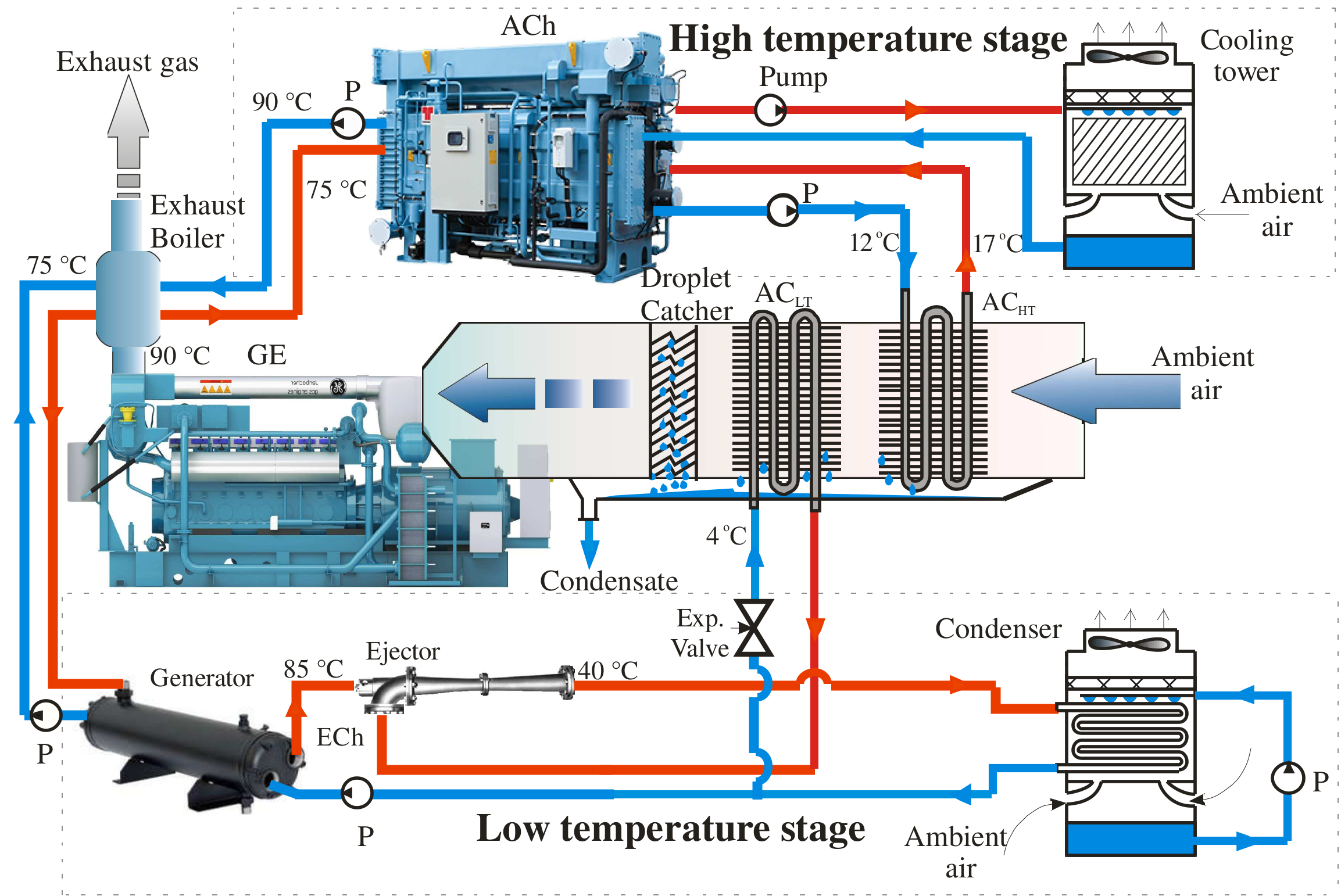
A new concept based on combined two-stage EIAC in ACh and ECh would enable the stabilization of the engine intake air at a low temperature. It could be realized by using chilled water from an ACh as a coolant in a high-temperature engine inlet air cooler and boiling refrigerant fed from an ECh—in a low-temperature air cooler [61].
The purpose of this research is to increase the fuel efficiency of a gas engine by combining two-stage inlet air cooling and estimate engine fuel efficiency enhancement on the basis of monitoring data.
2. Materials and Methods
2.1. General Assumptions and Hypothesis
So far as proposed, AECh systems are the advanced versions of traditional basic ACh systems, the economic comparison with the last might be done taking by into account only the cost of extra heat exchangers of ECh (refrigerant evaporator-air cooler, refrigerant condenser, refrigerant pump, and ejector) with an unchanged maintenance cost, personnel, etc. Because of variations in the cost of heat exchangers of different manufacturers and fuel especially, the economic analysis is to be conducted for the concrete case. Thus, the proposed method of designing the ACh system focuses on providing just initial basic data as rational technical characteristics further complicate a detailed economic analysis.
The hypotheses accepted to prove novel approaches to the principles of the proposed innovative AECh engine intake air cooling system operation are the following.
The heat influx to the engine room from heat exchangers (HExch) for the production of hot water through the removing of heat from gas engine cooling water, oil, scavenge air, exhaust gas, and heat influx to the engine room from surroundings causes, by insolation and heat transfer, a considerably (twice and more) increased thermal load on the typical engine intake air cooling (EIAC) system with intake air sucked by turbocharger from the engine room. Issuing from this point, it is not reasonable to cool all the ambient air coming into the engine room as in a typical central air conditioner, but just the engine turbocharger intake air or increasing its volume in account with the alternator cooling needs.
The assumptions adopted for the comparative analysis of the fuel efficiency of the basic types and developed EIAC systems are as follows:
The lowest temperature of air cooled in the ACh of a basic EIAC system is assumed to be ta2 = 20 °C and limited by the minimum temperature difference of 8 °C between cooled air and chilled water, leaving the ACh at tw = 12 °C (water at the inlet of air cooler): ta2 = tw + 8 °C.
In the case of using a refrigerant as a coolant in the low-temperature stage of the two-stage air cooler, the temperature difference between the air being cooled and boiling refrigerant is lower, 4 or 5 °C. Proceeding from this, the values of minimum temperature ta2 of air cooled in refrigerant chiller might be 10 °C and lower: ta2 = t0 + (4 or 5) °C.
The annual fuel reduction ∑B is used as a primary criterion.
2.2. Calculation Procedure
The annual fuel reduction ∑B gained due to cooling gas engine intake air at varying loading on the EIAC system in response to actual climatic conditions was calculated by summarizing current values of fuel reduction increments through the “hour-by-hour” procedure.
The real input data of on-site actual ambient air temperature tamb were taken by using the program “meteomanz”.
The current values of total fuel reduction per an hour were
where a specific fuel reduction (for 1 kW gas engine power output) for every 1 °C drop in engine intake air temperature is Δbe/Δt, engine intake air temperature depression in the air cooler is Δt = ta1 − ta2, and engine power output Pe, is taken according to monitoring data.
B = Δt·(Δbe/Δt)∙Pe
The annual fuel reduction was
ΣB = ΣΔt·τ (Δbe/Δt)∙Pe
The values of annual emission reduction were calculated proceeding from a reduction in CO2 emissions by 428.7 g and NOX by 2.78 g for each 1 m3 gas fuel reduction [62].
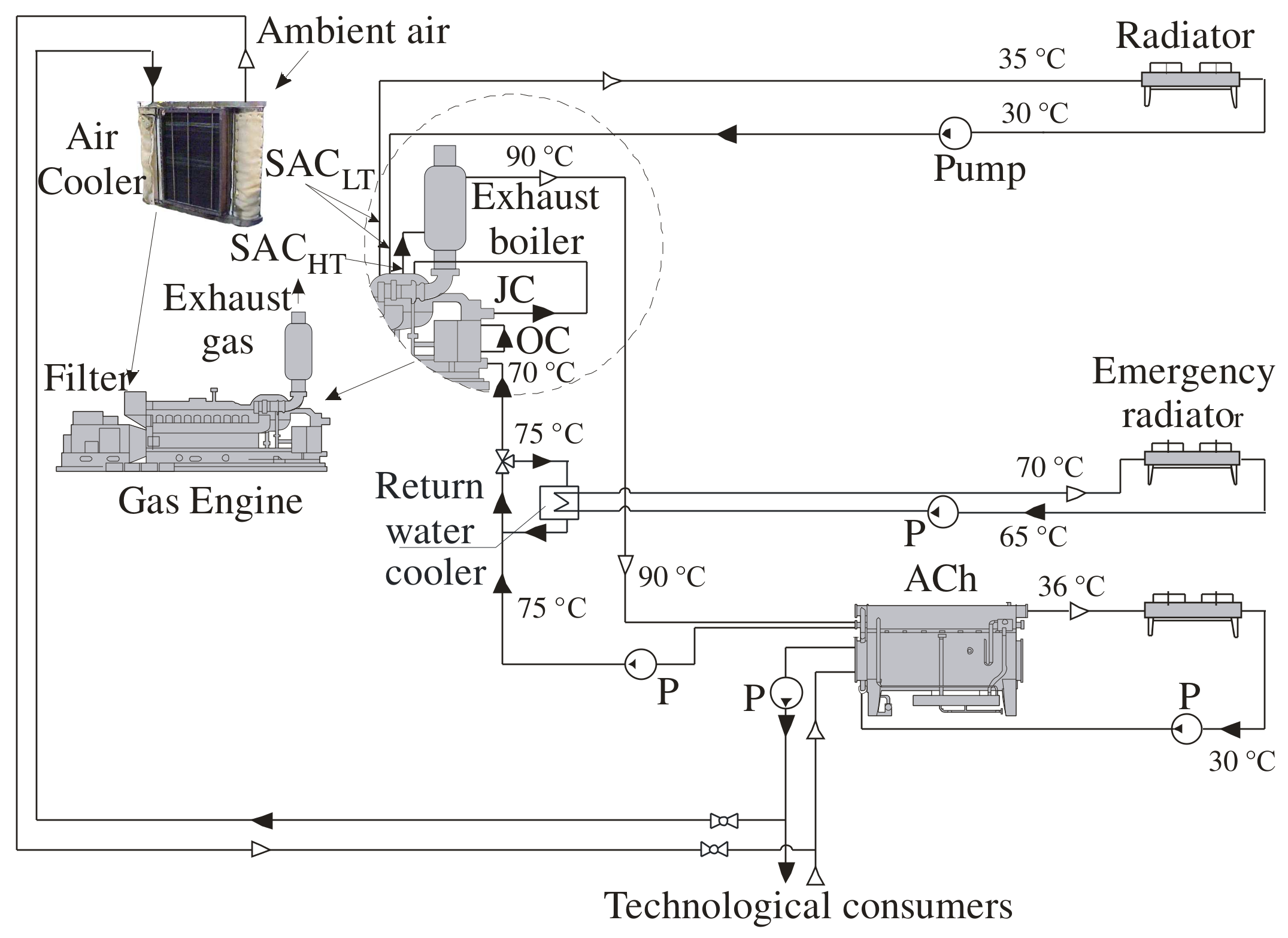
The heat of hot water (with a temperature of about 90 °C) produced by a cogenerative gas engine module, converted by the ACh of a simple cycle is limited by the hot water temperature drop, not more than 15 °C, in order to keep the COP of the ACh at a high level of about 0.7. As a result, the temperature of heating water at the outlet of the ACh is not lower than 75 °C. Meanwhile, the temperature of return cooled water at the inlet of the cogenerative gas engine module, used as a coolant to remove the heat from the engine, should not be higher than 70 °C in order to keep the engine at a safe thermal level. The excess of return warm water heat is traditionally extracted into the atmosphere by an emergency radiator (Figure 1). Thus, about 25% of hot water heat released from the gas engine can be converted into additional refrigeration capacity by refrigerant ECh as the simplest in design for further deeper cooling engine intake air precooled in ACh.
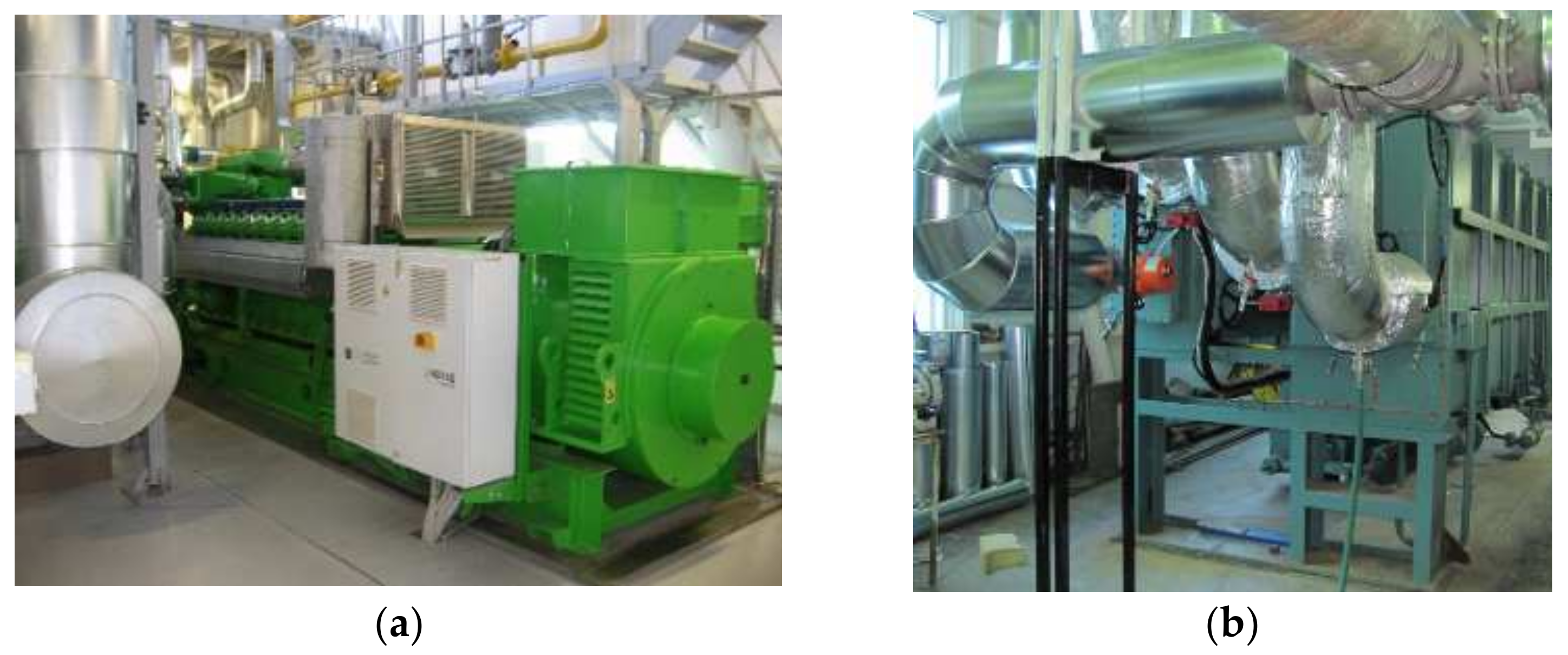
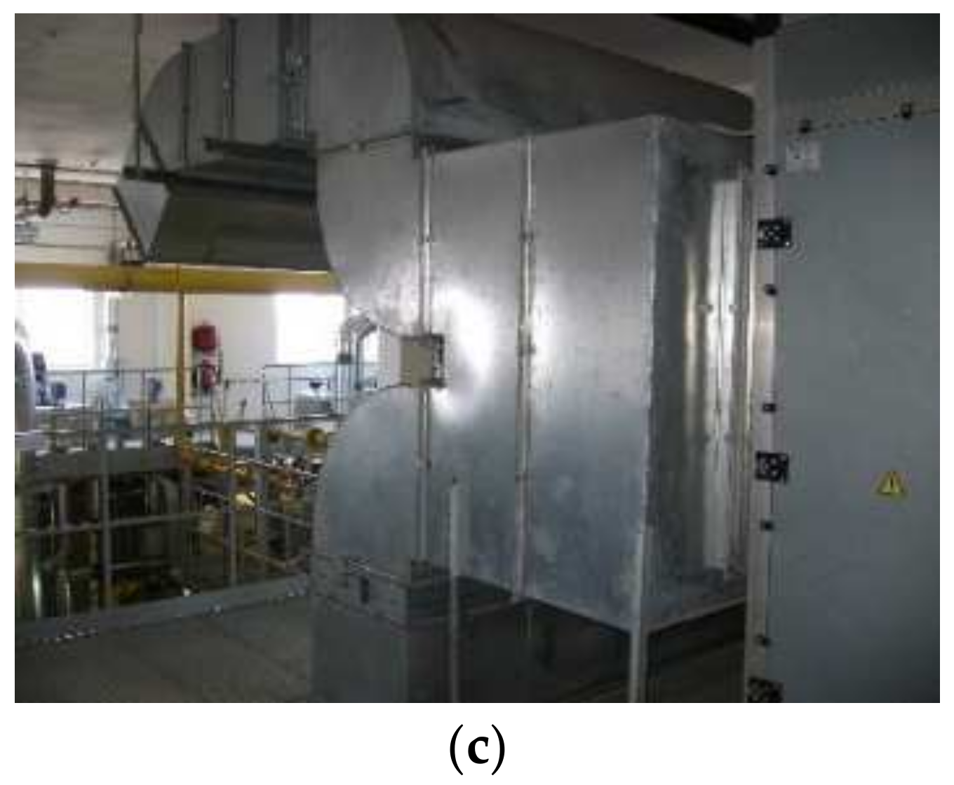
The efficiency of gas engine inlet air cooling is investigated for the trigeneration plant of “Sandora”–“PepsiCo Ukraine” (Mykolayiv, Ukraine). The trigeneration plant is equipped with two Jenbacher gas engines JMS 420 GS-N.LC (rated electric power PeISO = 1400 kW and heat Qh = 1500 kW) and ACh AR-D500L2 Century (Figure 2).
A typical scheme of gas engine inlet air cooling system is presented in Figure 3.
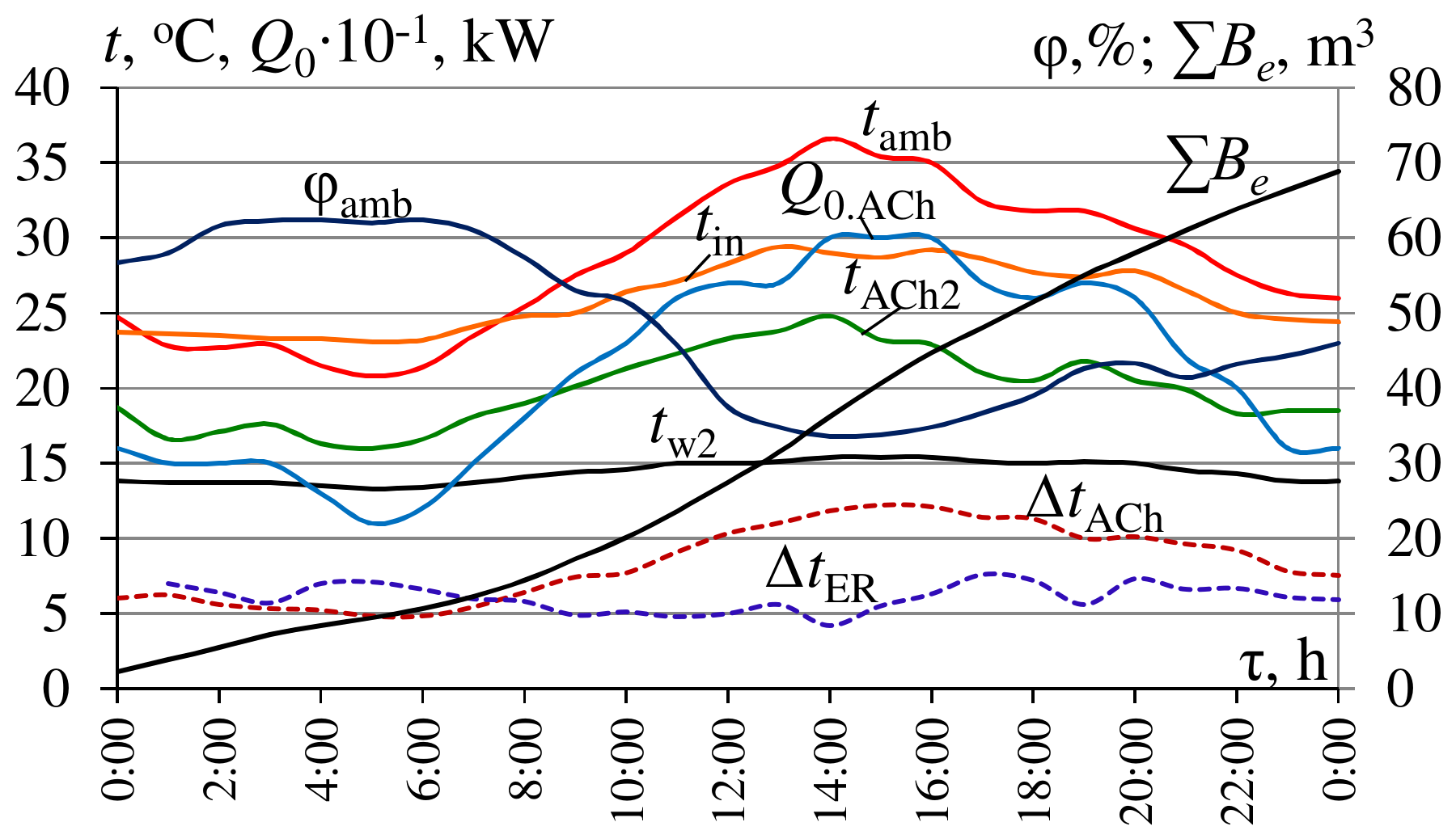
Because of the heat influx to cooled air stems from the engine room environment, the temperature of the air tin at the inlet of the engine is higher than its value tHT at the outlet of high-temperature air cooler ACHT of the central conditioner by air temperature increment ΔtER caused by heat influx: tin = tHT + ΔtER (Figure 4).
A considerably increased temperature of the air at the inlet of engine tin proves a non-effective operation of the conventional EIAC system by chilled water from an ACh with a temperature of 12 °C.
3. Results
In order to evaluate the effect of GE inlet air two-stage cooling, compared with conventional conditioning all the ambient air coming into the engine room, the data of gas engine JMS 420 GS-N.L fuel efficiency monitoring were used.
The results of monitoring a gas engine fuel efficiency were presented in the form of data sets on the dependence of fuel consumption Be = f(tin), power output Pe = f(tin), and specific fuel consumption be = Bf/Pe upon the air temperatures tin at the inlet of the engine turbocharger. A method for processing the monitoring data on fuel consumption and power output of the gas engine was developed [11,61].
The goal of processing the monitoring data sets Pe = f(tin), Be = f(tin), and be = f(tin) was to calculate the value of the change in specific fuel consumption Δbe caused by the change in the engine inlet air temperature tin by 1 °C, as Δbe/Δtin, to estimate the fuel-saving due to applying the advanced two-stage air cooling [48,61].
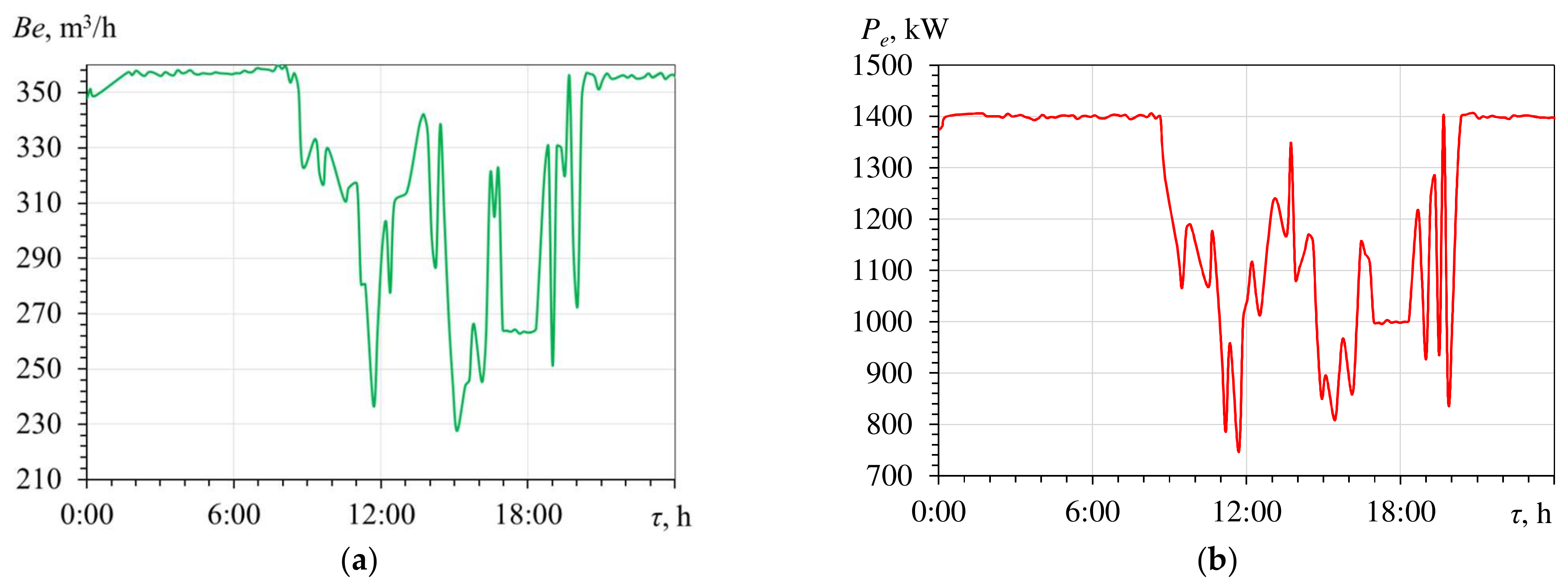
The daily variation of volume gas consumption Be and electric power Pe of engine JMS 420 GS based on monitoring data are presented in Figure 5, Figure 6 and Figure 7.
During hot summer days at time interval τ = 9…20 h the ambient air temperatures are increased: tamb = 30…35 °C, which makes it impossible to cool a charged gas-air mixture by the radiator to an appropriate level when the temperature is about 40 °C. This leads to an automatically decreasing gas supply to the engine and power output accordingly (Figure 5).
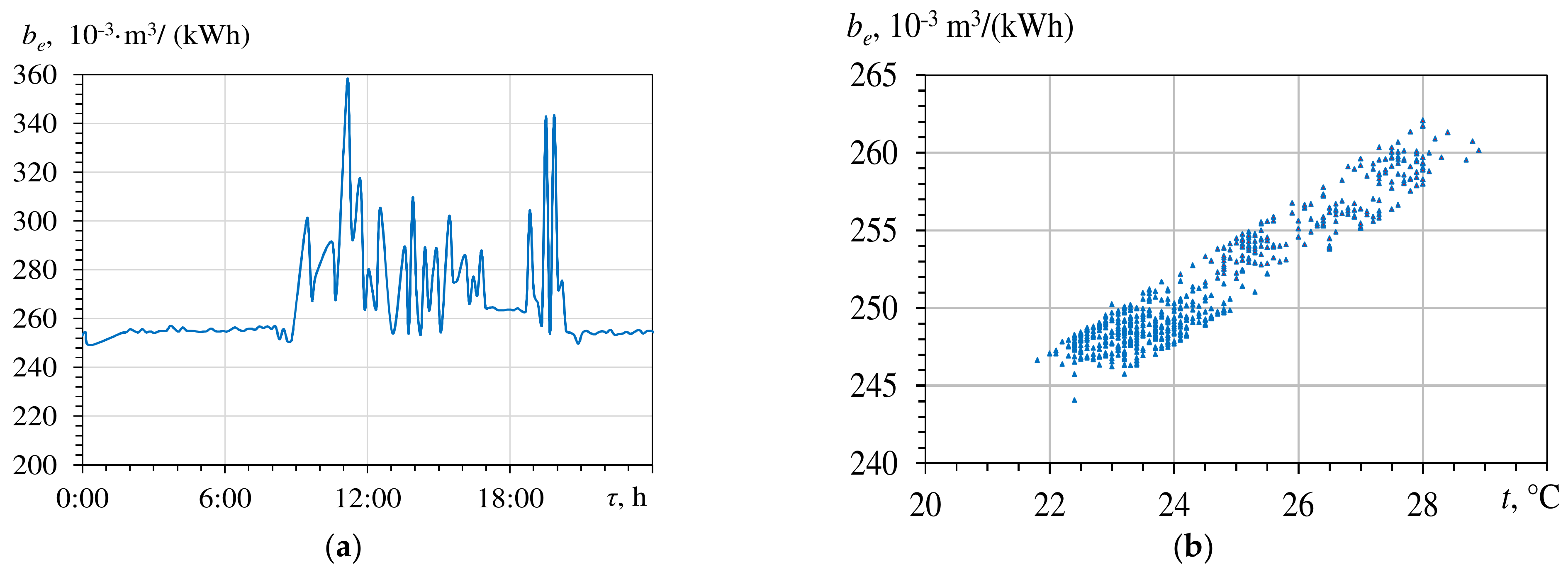
Performance of the gas engine at a raised intake air temperature tin (τ = 9…20 h) is followed by an increase in specific gas consumption be by (20…30) × 10–3 m3/(kWh) (Figure 5a), i.e., 8…12% compared with engine full loading at ambient air temperatures tamb and corresponding tin lower than 25 °C (τ = 2…9 h).
As Figure 6 shows, arising intake air temperature t causes a considerable increase in specific volume gas consumption be.
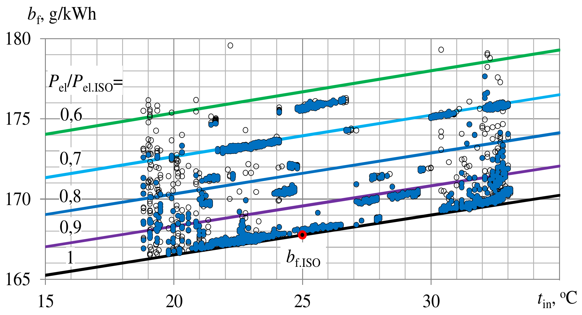
As Figure 7 shows, with decreasing engine inlet air temperatures tin the mass-specific fuel consumption bf reduces by 0.25 to 0.27 g/(kWh) for 1 °C drop of engine inlet air temperature ∆tin = 1 °C.
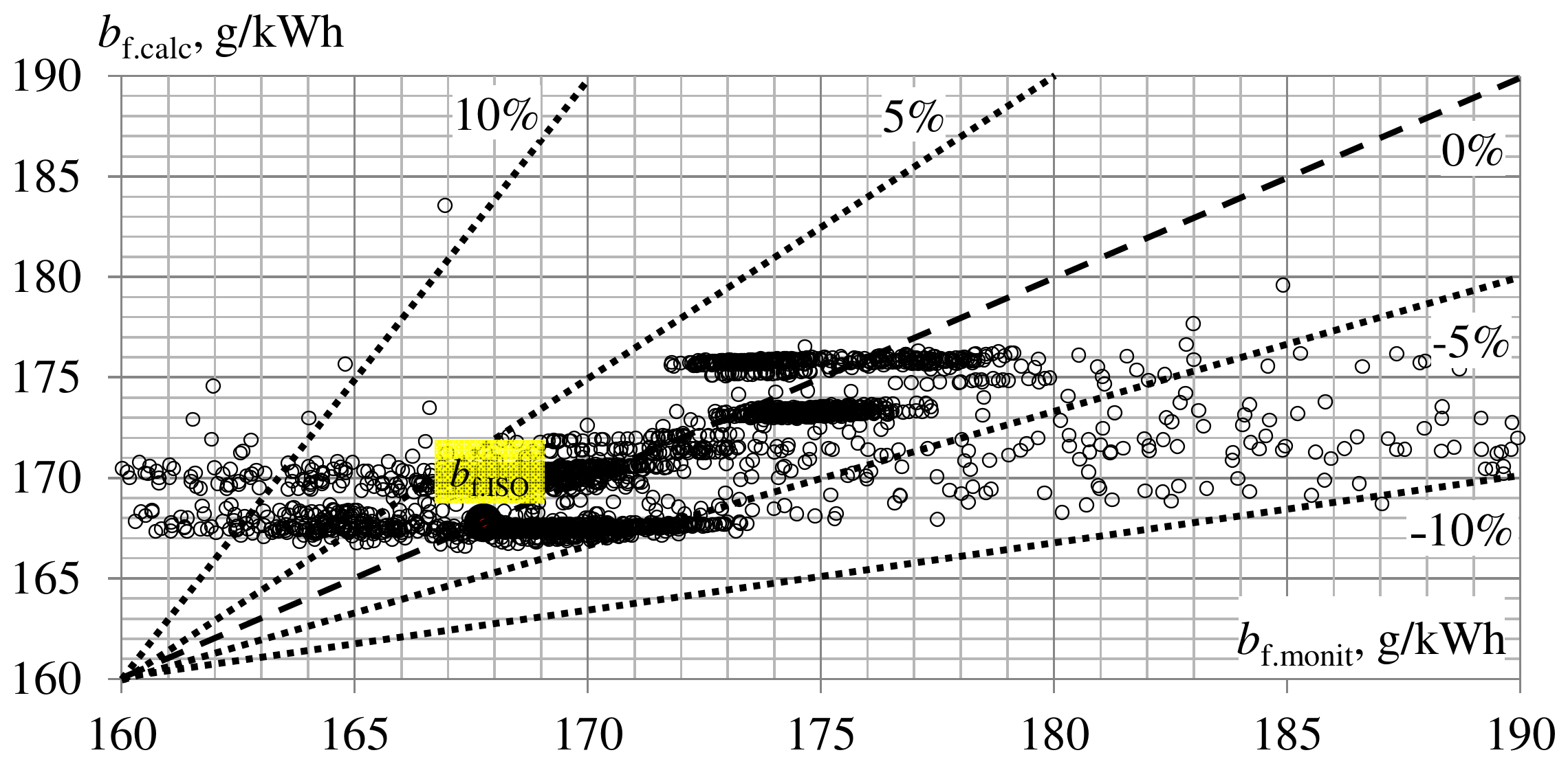
A deviation of calculated values of mass-specific fuel consumption bf.calc from monitoring data bf.monit is within the range of 10% with a probability of 95% and within the range of 5% with a probability of 65% (Figure 8).
Issuing from a reduction in specific fuel consumption bf with decreasing engine inlet air temperatures tin, a concept of addition inlet air subcooling compared with its typical cooling by chilled water with a temperature of about 12 °C in ACh, used for technological cooling needs, is developed (Figure 9).
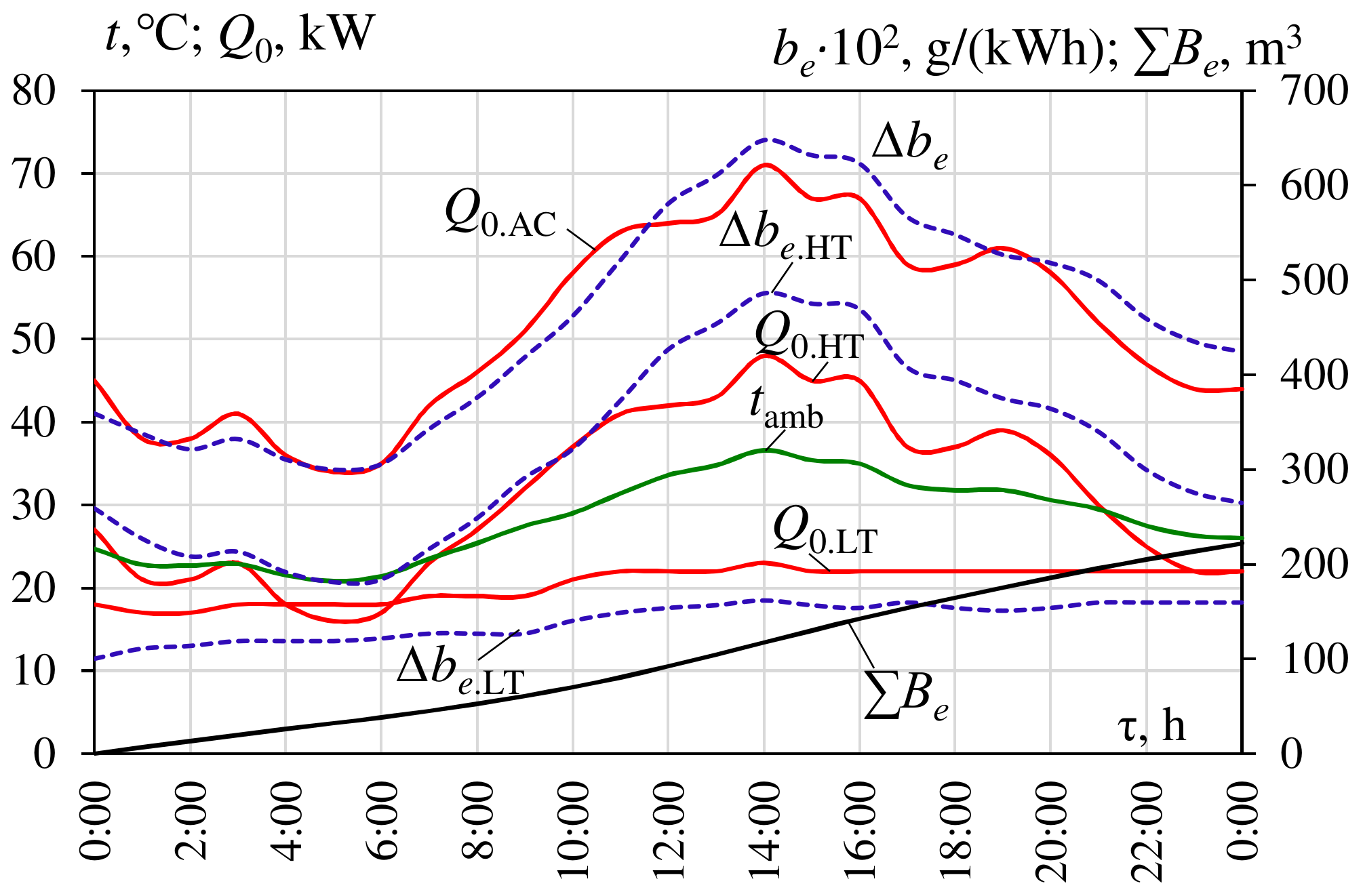
The calculation results of thermal loads Q0.HT and Q0.LT on high- and low-temperature air coolers and Q0.AC on the whole two-stage air cooler, based on the monitored air temperatures at the turbocharger inlet tin, indicates current specific fuel consumption decreases ∆be as well as daily summarized volume gas-saving ΣBe due to engine inlet air cooling in high-temperature cooler ACHT by ACh and low-temperature cooler ACLT by ECh. The overall gas-saving results for two-stage AECh are presented in Figure 10.
Thus, the developed combined two-stage engine inlet air cooling system enables the operation of GE at a practically stabilized low sucked air temperatures at variable actual climatic conditions. This results in a reduction of specific fuel consumption by about 3 to 5 g/(kWh) or in 3% at raised ambient air temperatures tamb.
4. Discussion
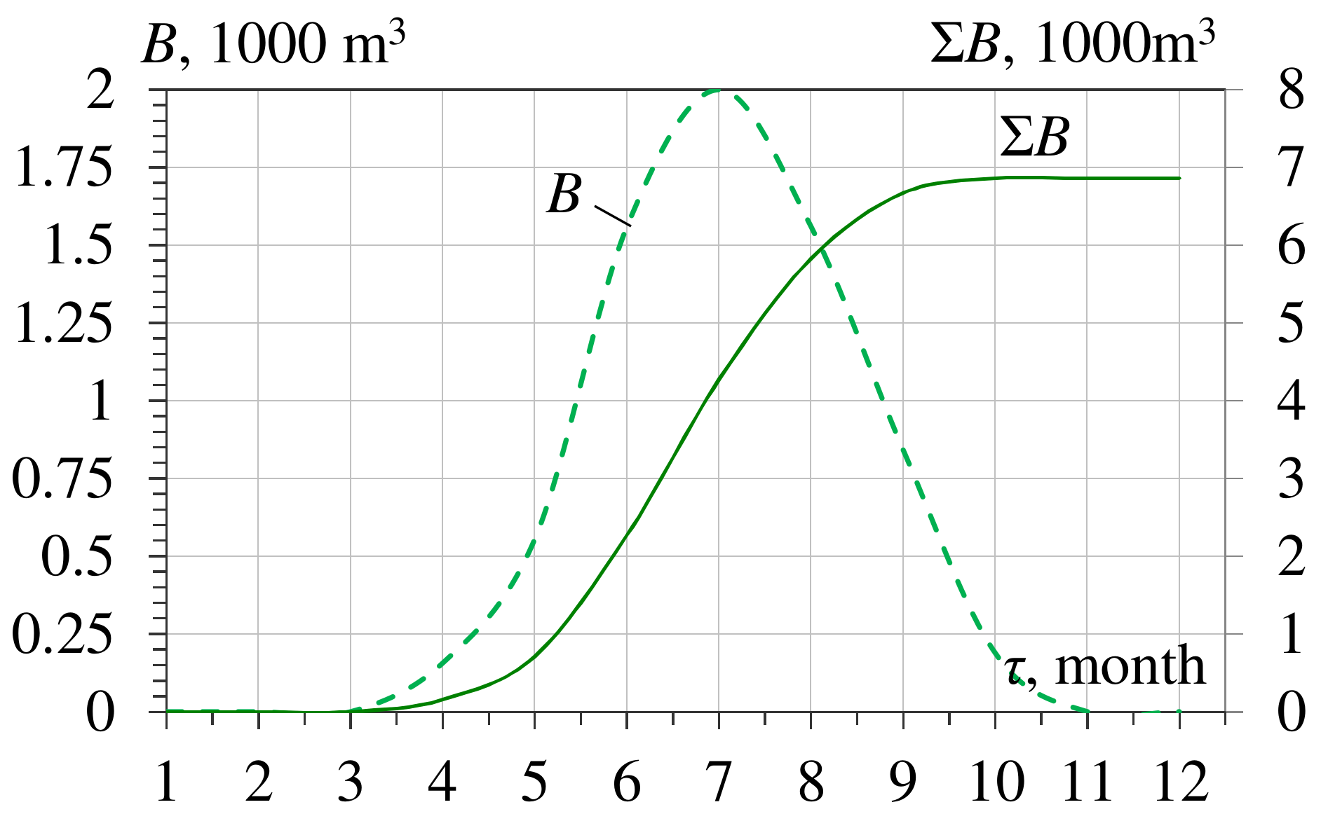
The application of a developed combined two-stage AECh engine inlet air cooling system enables the engine to operate at a practically stabilized low sucked air temperature at varying climatic conditions that result in monthly B and annual ΣB reduction of fuel consumption (Figure 11). With this, the annual fuel reduction ∑B is used as a primary criterion.
The annual fuel reduction ∑B gained due to cooling gas engine intake air at varying loading on the EIAC system in response to actual climatic conditions was calculated by summarizing the current values of fuel reduction increments through the “hour-by-hour” procedure.
The calculation results of the ecological effect due to engine intake air cooling in AECh in 2017 are presented in Figure 12. The values of the reduction in carbon dioxide ΣCO2 emissions for GE (power output 1.4 MW) due to intake air cooling in AECh are presented in Figure 12a and the reduction in ΣNOX emissions in Figure 12b.
The values of the annual emission reduction were calculated issuing from a reduction in CO2 emissions by 428.7 g and NOX by 2.78 g for each 1 m3 gas fuel reduction [62].
The system of TIAC in ACh and ECh consequently provides about 50% additional annual fuel saving compared with traditional air cooling in ACh for temperate climatic conditions (southern Ukraine) (Figure 13).
Due to minimizing the heat influx of turbocharger suctioned air from the environment, the two-stage air cooling system enables engine performance at stabilized low intake air temperatures at varying climatic conditions.
So far as the proposed, the AECh system is the advanced version of the traditional basic ACh system. The economic comparison with the former might be done taking into account only the cost of extra heat exchangers of ECh (refrigerant evaporator-air cooler, refrigerant condenser, and ejector) with an unchanged maintenance cost, personnel, etc.
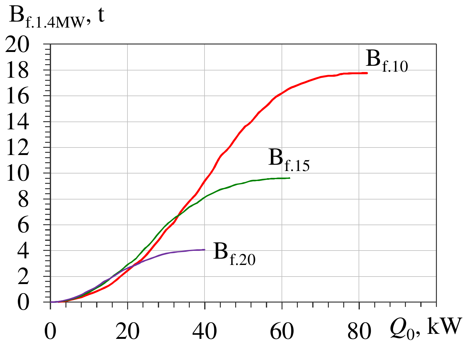
As a basic variant, the GE JMS 420 GS of the power output of 1.4 MW and air mass flow rate Ga =2 kg/s is accepted. According to Figure 10, Q0.10 = 80 kW for EIAC system with AECh and Q0.15 = 60 kW for the traditional ACh with corresponding annual fuel reduction ∑B10 = 17.5 t and ∑B15 = 9.4 t. Proceeding from these data, the value of the total cooling load on low-temperature ECh Q0.10-15 = Q0.10 − Q0.15, i.e., 20 kW, provides additional annual fuel reduction ∑B10–15 = ∑B10 − ∑B15 of about 8 t as compared with the traditional ACh system. Thus, the cooling capacity of a refrigerant evaporator-air cooler of ECh Q0.10–15 = 20 kW and of refrigerant condenser Qcondenser = Q0.10–15 (1 + COP), i.e., about 26 kW, where COP of ECh can be accepted as 0.3. Taking into account the cost of extra heat exchangers of ECh (about $4420 according to [63]) and including its additional 10% increase for ejectors and 10% for mounting, the cost of additional equipment of ECh is about $5300. On the other hand, the cost of gas fuel annually saved is about $8000 (proceeding from the price of gas $1000 per 1000 m3) and the payback period is less than a year.
The application of a cheap ECh as a low-temperature stage of AECh is quite reasonable in contrast to applying the additional (quite expensive) ACh that is able to produce chilled water of about 7 °C and was able to cool air lower than 15 °C. Additionally, the ECh cools air to 10 °C and has about a 50% additional annual fuel savings compared with cooling the air to 15 °C with an ACh (Figure 13). Furthermore, the ECh with refrigerant boiling at a temperature lower than 5 °C might be used to produce chilled water accumulated at decreased ambient air temperature and the thermal load on the EIAC system to cover peaked cooling needs.
Because of the fluctuations in the cost of heat exchangers of different manufacturers and the price of the gas fuel especially, the economic analysis is to be conducted for the concrete case. Thus, the considered method of designing focuses to provide just initial basic data as rational technical characteristics for further complicated detailed economic analysis.
5. Conclusions
An analysis of monitoring data on the fuel consumption of gas engine JMS 420 GS-N.L has proved the typical cooling of the ambient air incoming into the engine room in ACh with a chilled water temperature of about 12 °C, required for technological duties, is inefficient.
A novel concept of two-stage engine inlet air cooling in trigeneration IES for food industries is proposed which issues from the monitoring data on the reduction in specific fuel consumption with lowering the temperatures of air at the inlet of the engine. An engine intake air cooling (EIAC) system is developed that includes an ACh as a high-temperature stage for cooling ambient air to about 20 °C by chilled water of about 12 °C (used for technological needs) and refrigerant ejector chiller as the second low-temperature stage of EIAC that uses a cooling potential (not realized by Ach) for further cooling of the air to about 10 °C by boiling refrigerant.
A refrigerant ejector chiller (ECh) is the simplest in design, cheap and can be applied as the low-temperature stage of a two-stage absorption-ejector chiller (AECh) to provide engine intake air cooling and increase engine fuel efficiency as result.
The combined two-stage waste heat recovery cooling system developed is practically independent of load modes of technological cold consumers due to using a cooling potential not realized by an ACh and enables a high fuel efficiency of GE − reduction of specific fuel consumption of GE JMS 420 GS by 3 to 5 g/(kWh), and even uses the an additional cooling capacity generated by an ECh for technological needs resulting in a design that is more adaptable to changeable thermal loads.
The combined two-stage waste heat conversion provides an increase in the annual fuel saving by about 50% for a temperate climate as compared with typical EIAC based on an ACh.
The application of a cheap ECh as a low-temperature stage of AECh is quite reasonable in contrast to applying the additional, quite expensive, ACh that is able to produce chilled water of about 7 °C and cools air lower than 15 °C. Additionally, the ECh provides cooled air of about 10 °C and about 50% additional annual fuel saving compared with cooling the air to 15 °C in an ACh (Figure 13). Furthermore, the ECh with refrigerant boiling at a temperature lower than 5 °C might be used to produce chilled water accumulated at decreased ambient air temperature and thermal load on the EIAC system to cover peaked cooling needs.
Author Contributions
Conceptualization, A.R., M.R., and S.F.; methodology, M.R., A.R., D.M., and S.F.; software, A.R., R.R., and S.F.; validation, A.R., M.R., and R.R.; formal analysis, M.R., A.R., D.M., and A.P.; investigation, A.R., M.R., A.P., R.R., and S.F.; resources, A.R., R.R.; data curation, A.R., M.R., and S.F.; writing—original draft preparation, M.R., A.R., and R.R.; writing—review and editing, A.R., M.R., D.M., and A.P.; visualization, M.R., A.R., and R.R.; supervision, M.R.; project administration, M.R.; funding acquisition, A.P. All authors have read and agreed to the published version of the manuscript.
Funding
This research received no external funding.
Institutional Review Board Statement
Not applicable.
Informed Consent Statement
Not applicable.
Data Availability Statement
Not applicable.
Conflicts of Interest
The authors declare no conflict of interest.
Nomenclature and Units
| AC | air cooler | |
| ACHT | high-temperature air cooler | |
| ACLT | low-temperature air cooler | |
| ACh | absorption lithium-bromide chiller | |
| AECh | absorption-ejector chiller | |
| COP | coefficient of performance | |
| ECh | ejector chiller | |
| EIAC | engine intake air cooling | |
| HExch | heat exchangers | |
| O | optimal point for maximum rate of annual fuel reduction increment | |
| R | rational point for closed to maximum annual fuel reduction | |
| Symbols and units | ||
| B | total mass fuel consumption decrease, B = CDH (Δbe/Δt)∙Pe. | g, kg, t |
| be | specific fuel consumption | g/kWh |
| ca | specific heat of humid air | kJ/(kg·K) |
| CDH | CDH = Δt·τ | K∙h |
| damb | ambient air absolute humidity | g/kg |
| Ga | air mass flow rate | kg/s |
| Pe | power output | kW |
| Q0 | total cooling capacity, heat flow rate | kW |
| q0 | specific cooling capacity—per unit air mass flow rate | kW/(kg/s) or kJ/kg |
| t | temperature | °C |
| tamb | ambient air temperature | °C |
| ta2 | outlet air temperature | °C |
| t0 | refrigerant boiling temperature | °C |
| ξ | specific heat ratio of the total heat (latent and sensible) rejected from air to its sensible heat | |
| τ | time interval | h |
| φamb | ambient air relative humidity | % |
| Δbe | specific fuel consumption decrease | g/kWh |
| Δt | air temperature decrease | K, °C |
| ∑B10,15,20 | annual total fuel reduction due to cooling engine intake air to 10, 15, 20 °C | t |
| ∑b10,15,20 | annual specific fuel reduction (per 1 kW engine power output) due to cooling engine intake air to 10, 15, 20 °C | g, kg, t |
| Subscripts | ||
| a | air | |
| amb | ambient | |
| max | maximum | |
| opt | optimal | |
| rat | rational | |
References
- Zellner, S.; Burgtorf, J.; Kraft-Schäfer, D. (Eds.) Cogeneration & Trigeneration—How to Produce Energy Efficiently: A Practical Guide for Experts in Emerging and Developing Economies; Deutsche Gesellschaft für Internationale Zusammenarbeit (GIZ) GmbH: Bonn, Germany, 2016; 144p. [Google Scholar]
- Gluesenkamp, K.; Hwang, Y.; Radermacher, R. High efficiency micro trigeneration systems. Appl. Therm. Eng. 2013, 50, 1480–1486. [Google Scholar] [CrossRef]
- CIMAC Position Paper Gas Engine Aftertreatment Systems by CIMAC WG 17, Gas Engines, May 2017. Available online: https://www.cimac.com/cms/upload/Publication_Press/WG_Publications/CIMAC_WG17_2017_Aug_Position_Paper_Gas_Engine_Aftertreatment_Systems.pdf (accessed on 22 June 2021).
- Jenbacher. Available online: http://www.intma.ru/energetica/power_stations/thermal_ps_trigeneration_ru.html (accessed on 22 June 2021).
- Rocha, M.; Andreos, R.; Simões-Moreira, J.R. Performance tests of two small trigeneration pilot plants. Appl. Therm. Eng. 2012, 41, 84–91. [Google Scholar] [CrossRef]
- Suamir, I.N.; Tassou, S.A. Performance evaluation of integrated trigeneration and CO2 cooling systems. Appl. Therm. Eng. 2013, 50, 1487–1495. [Google Scholar] [CrossRef]
- Rodriguez-Aumente, P.A.; Rodriguez-Hidalgo, M.C.; Nogueira, J.I.; Lecuona, A.; Venegas, M.C. District heating and cooling for business buildings in Madrid. Appl. Therm. Eng. 2013, 50, 1496–1503. [Google Scholar] [CrossRef]
- Bassily, A.M. Performance improvements of the intercooled reheat recuperated gas-turbine cycle using absorption inlet-cooling and evaporative after-cooling. Appl. Energy 2004, 77, 249–272. [Google Scholar] [CrossRef]
- Popli, S.; Rodgers, P.; Eveloy, V. Gas turbine efficiency enhancement using waste heat powered absorption chillers in the oil and gas industry. Appl. Therm. Eng. 2013, 50, 918–931. [Google Scholar] [CrossRef]
- Popli, S.; Rodgers, P.; Eveloy, V. Trigeneration scheme for energy efficiency enhancement in a natural gas processing plant through turbine exhaust gas waste heat utilization. Appl. Energy 2012, 93, 623–636. [Google Scholar] [CrossRef]
- Radchenko, A.; Trushliakov, E.; Tkachenko, V.; Portnoi, B.; Prjadko, O. Improvement of the refrigeration capacity utilizing for the ambient air conditioning system. In Lecture Notes in Mechanical Engineering, Advanced Manufacturing Processes II, Proceedings of the 2nd Grabchenko’s International Conference on Advanced Manufacturing Processes (InterPartner-2020), Odessa, Ukraine, 8–11 September 2020; Tonkonogyi, V., Ivanov, V., Trojanowska, J., Oborskyi, G., Grabchenko, A., Pavlenko, I., Edl, M., Kuric, I., Dasic, P., Eds.; Springer: Cham, Switzerland, 2021; pp. 714–723. [Google Scholar] [CrossRef]
- Radchenko, M.; Radchenko, A.; Radchenko, R.; Kantor, S.; Konovalov, D.; Kornienko, V. Rational loads of turbine inlet air absorption-ejector cooling systems. Proc. Inst. Mech. Eng. Part A J. Power Energy 2021. [Google Scholar] [CrossRef]
- Canova, A.; Cavallero, C.; Freschi, F.; Giaccone, L.; Repetto, M.; Tartaglia, M. Optimal energy management. IEEE Ind. Appl. Mag. 2009, 15, 62–65. [Google Scholar] [CrossRef]
- Kalhori, S.B.; Rabiei, H.; Mansoori, Z. Mashad trigeneration potential–An opportunity for CO2 abatement in Iran. Energy Conv. Manag. 2012, 60, 106–114. [Google Scholar] [CrossRef]
- Radchenko, A.; Stachel, A.; Forduy, S.; Portnoi, B.; Rizun, O. Analysis of the efficiency of engine inlet air chilling unit with cooling towers. In Lecture Notes in Mechanical Engineering, Advances in Design, Simulation and Manufacturing III, Proceedings of the 3rd International Conference on Design, Simulation, Manufacturing: The Innovation Exchange, DSMIE-2020, Kharkiv, Ukraine, 9–12 June 2020; Ivanov, V., Pavlenko, I., Liaposhchenko, O., Machado, J., Edl, M., Eds.; Springer: Cham, Switzerland, 2020; pp. 322–331. [Google Scholar] [CrossRef]
- Freschi, F.; Giaccone, L.; Lazzeroni, P.; Repetto, M. Economic and environmental analysis of a trigeneration system for food-industry: A case study. Appl. Energy 2013, 107, 157–172. [Google Scholar] [CrossRef]
- Ortiga, J.; Bruno, J.C.; Coronas, A. Operational optimization of a complex trigeneration system connected to a district heating and cooling network. Appl. Therm. Eng. 2013, 50, 1536–1542. [Google Scholar] [CrossRef]
- Chua, K.J.; Chou, S.K.; Yang, W.M.; Yan, J. Achieving better energy-efficient air conditioning—A review of technologies and strategies. Appl. Energy 2013, 104, 87–104. [Google Scholar] [CrossRef]
- Komuro, T.; Ito, E.; Sonoda, T.; Tomita, Y.; Hidaka, K.; Shibutani, S. Power output augmentation of gas turbine combined cycle by inlet-air cooling system of chiller type under high ambient air temperature. Mitsubishi Heavy Ind. Tech. Rev. 2010, 47, 33–39. [Google Scholar]
- Mahmoudi, S.M.; Zare, V.; Ranjbar, F.; Farshi, L.J. Energy and exergy analysis of simple and regenerative gas turbines inlet air cooling using absorption refrigeration. Appl. Sci. 2009, 9, 2399–2407. [Google Scholar] [CrossRef]
- Al-Tahaineh, H. Cooling of compressor air inlet of a gas turbine power plant using ammonia-water vapor absorption system. Int. J. Energy Eng. 2013, 3, 267–271. [Google Scholar]
- Andi, B.; Venkatesan, J.; Suresh, S.; Mariappan, V. Experimental analysis of triple fluid vapour absorption refrigeration system driven by electrical energy and engine waste heat. Therm. Sci. 2019, 23, 2995–3001. [Google Scholar]
- Ghaebi, H.; Karimkashi, S.; Saidi., M.H. Integration of an absorption chiller in a total CHP site for utilizing its cooling production potential based on R-curve concept. Int. J. Refrig. 2012, 35, 1384–1392. [Google Scholar] [CrossRef]
- Al-Ibrahim, A.M.; Varnham, A. A review of inlet air-cooling technologies for enhancing the performance of combustion turbines in Saudi Arabia. Appl. Therm. Eng. 2010, 30, 1879–1888. [Google Scholar] [CrossRef]
- Konovalov, D.; Kobalava, H.; Radchenko, M.; Scurtu, I.-C.; Sviridov, V. Determination of the evaporation chamber optimal length of a low-flow aerothermopressor for gas turbines. In Lecture Notes in Mechanical Engineering, Advanced Manufacturing Processes II, Proceedings of the 2nd Grabchenko’s International Conference on Advanced Manufacturing Processes (InterPartner-2020), Odessa, Ukraine, 8–11 September 2020; Tonkonogyi, V., Ivanov, V., Trojanowska, J., Oborskyi, G., Grabchenko, A., Pavlenko, I., Edl, M., Kuric, I., Dasic, P., Eds.; Springer: Cham, Switzerland, 2021; pp. 654–663. [Google Scholar] [CrossRef]
- Konovalov, D.; Kobalava, H.; Radchenko, M.; Scurtu, I.C.; Radchenko, R. Determination of hydraulic resistance of the aerothermopressor for gas turbine cyclic air cooling. In Proceedings of the TE-RE-RD 2020, E3S Web of Conferences, Constanta, Romania, 26–27 June 2020; EDP Sciences: Les Ulis, France; Volume 180. [Google Scholar] [CrossRef]
- Lawrence, N.; Elbel, S. Experimental investigation of a two-phase ejector cycle suitable for use with low-pressure refrigerants R134a and R1234yf. Int. J. Refrig. 2014, 38, 310–322. [Google Scholar] [CrossRef]
- Butrymowicz, D.; Gagan, J.; Śmierciew, K.; Łukaszuk, M.; Dudar, A.; Pawluczuk, A.; Łapiński, A.; Kuryłowic, A. Investigations of prototype ejection refrigeration system driven by low grade heat. In Proceedings of the HTRSE-2018, E3S Web of Conferences, Międzyzdroje, Poland, 2–5 September 2018; EDP Sciences: Les Ulis, France; Volume 70. [Google Scholar]
- Smierciew, K.; Gagan, J.; Butrymowicz, D.; Karwacki, J. Experimental investigations of solar driven ejector air-conditioning system. Energy Build. 2014, 80, 260–267. [Google Scholar] [CrossRef]
- Elbel, S.; Lawrence, N. Review of recent developments in advanced ejector technology. Int. J. Refrig. 2016, 62, 1–18. [Google Scholar] [CrossRef]
- Bohdal, T.; Kuczynski, W. Boiling of R404A refrigeration medium under the conditions of periodically generated disturbances. Heat Transf. Eng. 2011, 32, 359–368. [Google Scholar] [CrossRef]
- Kuczyski, W.; Charun, H.; Bohdal, T.; Kuczynski, W. Influence of hydrodynamic instability on the heat transfer coefficient during condensation of R134a and R404A refrigerants in pipe mini-channels. Int. J. Heat Mass Transf. 2012, 55, 1083–1094. [Google Scholar] [CrossRef]
- Dizaji, H.S.; Hu, E.J.; Chen, L.; Pourhedayat, S. Using novel integrated Maisotsenko cooler and absorption chiller for cooling of gas turbine inlet air. Energy Convers. Manag. 2019, 195, 1067–1078. [Google Scholar] [CrossRef]
- Zhu, G.; Chow, T.-T.; Lee, C.-K. Performance analysis of biogas-fueled Maisotsenko combustion turbine cycle. Appl. Therm. Eng. 2021, 195, 117247. [Google Scholar] [CrossRef]
- Yanga, Y.; Wangd, B.; Zhoue, Q. Air Conditioning System Design using Free Cooling Technology and Running Mode of a Data Center in Jinan. Procedia Eng. 2017, 205, 3545–3549. [Google Scholar] [CrossRef]
- Eidan, A.A.; Alwan, K.J. Enhancement of the Performance Characteristics for Air-Conditioning System by Using Direct Evaporative Cooling in Hot Climates. Energy Procedia 2017, 142, 3998–4003. [Google Scholar] [CrossRef]
- Ojha, M.R.; Shukla, A.K.; Verma, P.; Kannojiya, R. Recent progress and outlook of solar adsorption refrigeration systems. Mater. Today Proc. 2020, 46, 5639–5646. [Google Scholar] [CrossRef]
- Solovyev, A.; Pustovgar, A.; Shilova, L.; Adamtsevich, A.; Solovev, D. Simulating power efficiency of heat transfer agent cooling recirculation systems at power plants. Procedia Eng. 2016, 165, 1275–1280. [Google Scholar] [CrossRef]
- Kornienko, V.; Radchenko, M.; Radchenko, R.; Konovalov, D.; Andreev, A.; Pyrysunko, M. Improving the efficiency of heat recovery circuits of cogeneration plants with combustion of water-fuel emulsions. Therm. Sci. 2021, 25, 791–800. [Google Scholar] [CrossRef] [Green Version]
- Patel, K.R.; Dhiman, V. Research study of water-diesel emulsion as alternative fuel in diesel engine—An overview. Int. J. Latest Eng. Res. Appl. 2017, 2, 37–41. [Google Scholar]
- Chen, H.; Pan, P.; Wang, Y.; Zhao, Q. Field study on the corrosion and ash deposition of low–temperature heating surface in a large–scale coal–fired power plant. Fuel 2017, 208, 149–159. [Google Scholar] [CrossRef]
- Landet, R.D. PM Emissions and NOx—Reduction Due to Water in Fuel Emulsions in Marine Diesel Engines. Master’s Thesis, Norwegian University of Scienceand Technology, Department of Marine Technology, Trondheim, Norway, 2010; 73p. Available online: https://ntnuopen.ntnu.no/ntnu-xmlui/bitstream/handle/11250/237793/375078_FULLTEXT01.pdf?sequence=1&isAllowed=yhttp://hdl.handle.net/11250/237793 (accessed on 22 June 2021).
- Patel, N.; Modi, M.; Patel, T. Investigation of diesel engine with water emulsifier—A review. Int. Res. J. Eng. Technol. 2017, 4, 879–883. [Google Scholar]
- Miao, Y.C.; Yu, C.L.; Wang, B.H.; Chen, K. The applied research of emulsified heavy fuel oil used for the marine diesel engine. Adv. Mater. Res. 2013, 779, 469–476. [Google Scholar] [CrossRef]
- Elberry, M.F. Performance improvement of power plants using absorption cooling system. Alex. Eng. J. 2018, 57, 2679–2686. [Google Scholar] [CrossRef]
- Chacartegui, R.; Jiménez-Espadafor, F.; Sánchez, D.; Sánchez, T. Analysis of combustion turbine inlet air cooling systems applied to an operating cogeneration power plant. Energy Convers. Manag. 2008, 49, 2130–2141. [Google Scholar] [CrossRef]
- Forsyth, J.L. Gas turbine inlet air chilling for LNG. IGT Int. Liq. Nat. Gas Conf. Proc. 2013, 3, 1763–1778. [Google Scholar]
- Radchenko, A.; Trushliakov, E.; Kosowski, K.; Mikielewicz, D.; Radchenko, M. Innovative turbine intake air cooling systems and their rational designing. Energies 2020, 13, 6201. [Google Scholar] [CrossRef]
- Marques, R.P.; Hacon, D.; Tessarollo, A.; Parise, J.A.R. Thermodynamic analysis of tri-generation systems taking into account refrigeration, heating and electricity load demands. Energy Build. 2010, 42, 2323–2330. [Google Scholar] [CrossRef]
- Konur, O.; Saatcioglu, O.Y.; Korkmaz, S.A.; Erdogan, A.; Colpan, C.O. Heat exchanger network design of an organic Rankine cycle integrated waste heat recovery system of a marine vessel using pinch point analysis. Int. J. Energy Res. 2020, 44, 12312–12328. [Google Scholar] [CrossRef]
- Kuznetsov, V.; Dymo, B.; Kuznetsova, S.; Bondarenko, M. Improvement of the cargo fleet vessels power plants ecological indexes by development of the exhaust gas systems. Pol. Marit. Res. 2021, 28, 97–104. [Google Scholar] [CrossRef]
- Radchenko, M.; Mikielewicz, D.; Tkachenko, V.; Klugmann, M.; Andreev, A. Enhancement of the operation efficiency of the transport air conditioning system. In Lecture Notes in Mechanical Engineering, Advances in Design, Simulation and Manufacturing III, Proceedings of the 3rd International Conference on Design, Simulation, Manufacturing: The Innovation Exchange, DSMIE-2020, Kharkiv, Ukraine, 9–12 June 2020; Ivanov, V., Pavlenko, I., Liaposhchenko, O., Machado, J., Edl, M., Eds.; Springer: Cham, Switzerland, 2020; pp. 332–342. [Google Scholar] [CrossRef]
- Lee, J.H.; Yoon, H.J.; Im, P.; Song, Y.-H. Verification of energy reduction effect through control optimization of supply air temperature in VRF-OAP system. Energies 2018, 11, 49. [Google Scholar] [CrossRef] [Green Version]
- Southard, L.E.; Liu, X.; Spitler, J.D. Performance of HVAC systems at ASHRAE HQ. ASHRAE J. 2014, 56, 14–24. [Google Scholar]
- Trushliakov, E.; Radchenko, A.; Radchenko, M.; Kantor, S.; Zielikov, O. The efficiency of refrigeration capacity regulation in the ambient air conditioning systems. In Lecture Notes in Mechanical Engineering, Advances in Design, Simulation and Manufacturing III, Proceedings of the 3rd International Conference on Design, Simulation, Manufacturing: The Innovation Exchange, DSMIE-2020, Kharkiv, Ukraine, 9–12 June 2020; Ivanov, V., Pavlenko, I., Liaposhchenko, O., Machado, J., Edl, M., Eds.; Springer: Cham, Switzerland, 2020; pp. 343–353. [Google Scholar] [CrossRef]
- Fumo, N.; Mago, P.J.; Smith, A.D. Analysis of combined cooling, heating, and power systems operating following the electric load and following the thermal load strategies with no electricity export. Proc. Inst. Mech. Eng. Part A J. Power Energy 2011, 225, 1016–1025. [Google Scholar] [CrossRef]
- Barreto, D.; Fajardo, J.; Carrillo Caballero, G.; Cardenas Escorcia, Y. Advanced exergy and exergoeconomic analysis of a gas power system with steam injection and air cooling with a compression refrigeration machine. Energy Technol. 2021, 9, 2000993. [Google Scholar] [CrossRef]
- Oktay, Z.; Coskun, C.; Dincer, I. A new approach for predicting cooling degree-hours and energy requirements in buildings. Energy 2011, 36, 4855–4863. [Google Scholar] [CrossRef]
- Coskun, C.; Demiral, D.; Ertürk, M.; Oktay, Z. Modified Degree-Hour Calculation Method. In Solar Power; Rugescu, R., Ed.; InTech: Gunpo, Korea, 2012; ISBN 978-953-51-0014-0. [Google Scholar]
- Coskun, C. A novel approach to degree-hour calculation: Indoor and outdoor reference temperature based degree-hour calculation. Energy 2010, 35, 2455–2460. [Google Scholar] [CrossRef]
- Radchenko, A.; Mikielewicz, D.; Radchenko, M.; Forduy, S.; Rizun, O.; Khaldobin, V. Innovative combined in-cycle trigeneration technologies for food industries. In Proceedings of the V International Scientific and Technical Conference Modern Power Systems and Units (MPSU 2021), E3S Web of Conferences, Krakow, Poland, 19–21 May 2021; EDP Sciences: Les Ulis, France; Volume 323. [Google Scholar] [CrossRef]
- Sytnikov, V. Ecological Advantages of Cogeneration; ECKO-Journal of Energy-Service Company (Ecological Systems): Kyiv, Ukraine, 2005; 7p. [Google Scholar]
- Guentner. Available online: https://www.guentner.eu/know-how/product-calculator-gpc/gpc-software/ (accessed on 22 June 2021).
Figure 1.
A schema of a typical system of cogenerative gas engine heat conversion by ACh with engine intake air cooling in the air cooler of the central conditioner by chilled water from the ACh: OC-oil cooler; JC-jacket cooler; SACLT and SACHT -low- and high-temperature scavenge air coolers.
Figure 1.
A schema of a typical system of cogenerative gas engine heat conversion by ACh with engine intake air cooling in the air cooler of the central conditioner by chilled water from the ACh: OC-oil cooler; JC-jacket cooler; SACLT and SACHT -low- and high-temperature scavenge air coolers.

Figure 2.
Gas engine module JMS GE Jenbacher (a), absorption chiller AR-D500L2 (b), and central conditioner for engine room incoming air cooling (c).
Figure 2.
Gas engine module JMS GE Jenbacher (a), absorption chiller AR-D500L2 (b), and central conditioner for engine room incoming air cooling (c).


Figure 3.
A scheme of a typical system of gas engine inlet air cooling in the central conditioner by chilled water from an ACh.
Figure 3.
A scheme of a typical system of gas engine inlet air cooling in the central conditioner by chilled water from an ACh.
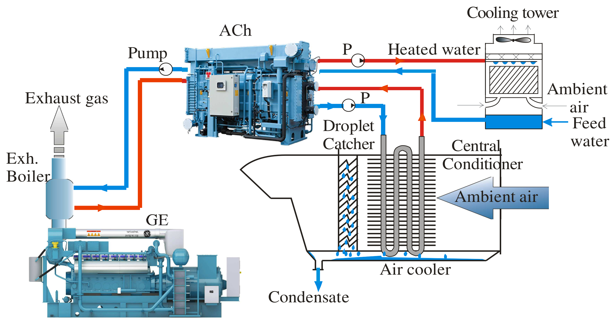
Figure 4.
Daily variations in temperature tamb and relative humidity φamb of ambient air, temperature of air at the gas engine inlet tin, and at the high-temperature air cooler outlet tACh2 = tHT, ΔtACh = ΔtHT = tamb − tHT; ΔtER = tin − tHT.
Figure 4.
Daily variations in temperature tamb and relative humidity φamb of ambient air, temperature of air at the gas engine inlet tin, and at the high-temperature air cooler outlet tACh2 = tHT, ΔtACh = ΔtHT = tamb − tHT; ΔtER = tin − tHT.

Figure 5.
Daily variation of volume gas consumption Be (a) and electric power Pe (b) of the gas engine against time τ.
Figure 5.
Daily variation of volume gas consumption Be (a) and electric power Pe (b) of the gas engine against time τ.

Figure 6.
Specific volume gas consumption be aa a daily variation against time τ (a) and inlet air temperature t (b).
Figure 6.
Specific volume gas consumption be aa a daily variation against time τ (a) and inlet air temperature t (b).

Figure 7.
Variation of mass-specific fuel consumption bf against inlet air temperature tin at various loads Pel/Pel.ISO, Pel—electrical power as monitored data; Pel.ISO—rated electrical power at ISO ambient air parameters: tamb = 25 °C, and relative humidity φamb = 30%.
Figure 7.
Variation of mass-specific fuel consumption bf against inlet air temperature tin at various loads Pel/Pel.ISO, Pel—electrical power as monitored data; Pel.ISO—rated electrical power at ISO ambient air parameters: tamb = 25 °C, and relative humidity φamb = 30%.

Figure 8.
Mass specific fuel consumption calculated values bf.calc against monitoring data bf.monit.
Figure 8.
Mass specific fuel consumption calculated values bf.calc against monitoring data bf.monit.

Figure 9.
A two-stage absorption-ejector (AECh) system for chilling engine inlet air: ACHT and ACLT—high- and low-temperature air coolers; P—pump.
Figure 9.
A two-stage absorption-ejector (AECh) system for chilling engine inlet air: ACHT and ACLT—high- and low-temperature air coolers; P—pump.

Figure 10.
Daily variation of thermal loads Q0.HT and Q0.LT on high- and low-temperature air coolers and Q0.AC on the whole two-stage air cooler; Q0.HT and decreases of specific fuel consumption ∆be.HT, ∆be.LT, ∆be, accordingly, and summarized volume gas-saving ΣBe (Mykolayiv region, south of Ukraine, 2017).

Figure 11.
Monthly B and annual fuel saving ΣB for gas engine JMS 420 GS due to inlet air cooling in AECh (Mykolayiv region, south of Ukraine, 2017).
Figure 11.
Monthly B and annual fuel saving ΣB for gas engine JMS 420 GS due to inlet air cooling in AECh (Mykolayiv region, south of Ukraine, 2017).

Figure 12.
Monthly CO2 and annual ΣCO2 (a) and monthly NOx and annual ΣNOx (b) emission reduction due to engine inlet air cooling in AECh (Mykolayiv, southern Ukraine, 2017).
Figure 12.
Monthly CO2 and annual ΣCO2 (a) and monthly NOx and annual ΣNOx (b) emission reduction due to engine inlet air cooling in AECh (Mykolayiv, southern Ukraine, 2017).
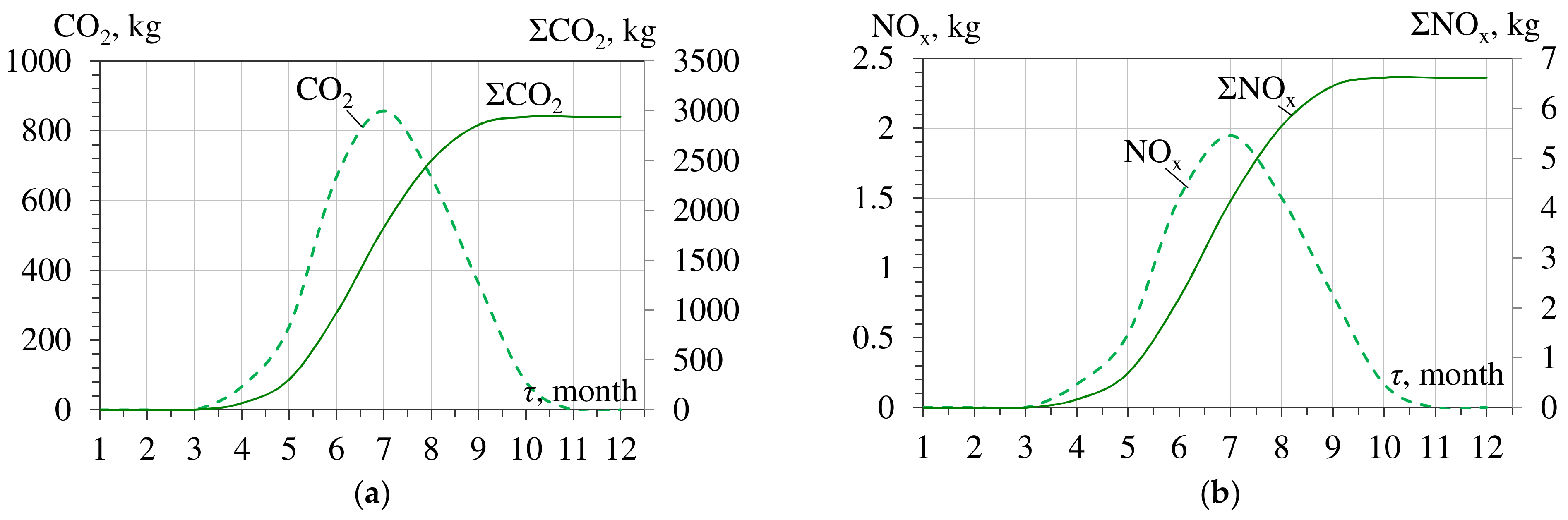
Figure 13.
Annual fuel-saving ΣB Bf versus design cooling capacities Q0 of chillers for engine intake air temperatures at 15 and 20 °C in ACh and 10 °C in AECh (Mykolayiv region, south of Ukraine, 2017).
Figure 13.
Annual fuel-saving ΣB Bf versus design cooling capacities Q0 of chillers for engine intake air temperatures at 15 and 20 °C in ACh and 10 °C in AECh (Mykolayiv region, south of Ukraine, 2017).
Publisher’s Note: MDPI stays neutral with regard to jurisdictional claims in published maps and institutional affiliations. |
© 2022 by the authors. Licensee MDPI, Basel, Switzerland. This article is an open access article distributed under the terms and conditions of the Creative Commons Attribution (CC BY) license (https://creativecommons.org/licenses/by/4.0/).
Share and Cite
MDPI and ACS Style
Radchenko, A.; Radchenko, M.; Mikielewicz, D.; Pavlenko, A.; Radchenko, R.; Forduy, S. Energy Saving in Trigeneration Plant for Food Industries. Energies 2022, 15, 1163. https://doi.org/10.3390/en15031163
AMA Style
Radchenko A, Radchenko M, Mikielewicz D, Pavlenko A, Radchenko R, Forduy S. Energy Saving in Trigeneration Plant for Food Industries. Energies. 2022; 15(3):1163. https://doi.org/10.3390/en15031163
Chicago/Turabian StyleRadchenko, Andrii, Mykola Radchenko, Dariusz Mikielewicz, Anatoliy Pavlenko, Roman Radchenko, and Serhiy Forduy. 2022. "Energy Saving in Trigeneration Plant for Food Industries" Energies 15, no. 3: 1163. https://doi.org/10.3390/en15031163
Note that from the first issue of 2016, this journal uses article numbers instead of page numbers. See further details here.