Article

Implementation of an Alternative Frequency-Dependent Three-Phase Transmission Line Model Based on the Folded Line Equivalent Model in MatLab-Simulink

by
Jaimis Sajid Leon Colqui
1,*,
Luis Timaná
2,
Pablo Torrez Caballero
1,3,
José Pissolato Filho
1 and
Sérgio Kurokawa
4
1
School of Electrical and Computer Engineering, State University of Campinas (UNICAMP), Campinas 13083-852, Brazil
2
Department of Electronic and Telecommunications Engineering, Catholic University of Colombia, Bogotá 110231, Colombia
3
Research and Development Center in Telecommunications (CPQD), Campinas 13086-902, Brazil
4
Department of Electrical Engineering, São Paulo State University (UNESP), Ilha Solteira 15385-000, Brazil
*
Author to whom correspondence should be addressed.
Energies 2022, 15(24), 9302; https://doi.org/10.3390/en15249302
Submission received: 5 February 2022 / Revised: 28 February 2022 / Accepted: 9 March 2022 / Published: 8 December 2022
(This article belongs to the Topic Power System Modeling and Control, 2nd Volume)

Abstract

:
This paper proposes an alternative multiconductor transmission line model that combines the folded line equivalent with the modal transformation. The folded line equivalent decomposes the nodal admittance matrix of a transmission line into its open-circuit and short-circuit contributions. These contributions are fitted to rational functions, which are associated with Norton equivalent circuits based on their state space models. The proposed model uses an orthogonal matrix to transform voltages and currents from the phase domain to the folded line equivalent domain and vice versa. Because the transformation matrix is orthogonal, we represent it using ideal transformers in simulation software. First, we use a circuit representation of Clarke’s matrix to decompose a transmission line into its modes. Then, each mode is decomposed into its open-circuit and short-circuit contributions using a circuit implementation of the proposed matrix. The proposed approach can accurately represent short lines in simulations with time steps equal to or greater than the propagation time of the transmission line. We compare the results obtained with the proposed approach to those obtained with power systems computer-aided design/electromagnetic transients including the DC universal line model.

1. Introduction and Literature Review

Frequency-dependent cable and transmission line (TL) models have been widely used in the study of electromagnetic transients in power systems. These models can be developed in the modal domain or directly in the phase domain. For instance, the JMarti model, introduced in [1], assumes a constant matrix to transform electrical parameters to the mode domain and vice versa. This assumption is valid for ideally transposed TLs and gives good results for non-transposed TLs with vertical symmetry. For this reason, the JMarti model is available as a built-in model in simulation software such as the Alternative Transient Program-Electromagnetic Transients Program (ATP-EMTP) [2]. However, assuming frequency-independent transformation matrices is not valid for non-transposed asymmetric lines or parallel circuits. Other TL models that do not make this assumption are preferred for these cases e.g., the universal line model (ULM) [3]. The ULM computes voltages and currents directly in the phase domain and is considered one of the most accurate and general models for the simulation of overhead transmission lines and cables. The ULM is available as a built-in model in simulation software such as the Power Systems Computer Aided Design (PSCAD) [4] and the Electromagnetic Transients Program—Restructured Version (EMTP-RV) [5].
Numerous transmission line models (including the ULM and the JMarti model) derive from the method of characteristics. The method of characteristics requires (simulation) time steps to be smaller than the propagation time of the transmission line. Therefore, the time step used in the simulation of complex power systems is limited to the propagation time of the shortest line [6,7]. The folded line equivalent (FLE) [8] circumvents this problem. The FLE decouples a TL into two blocks that represent the short-circuit and open-circuit contributions of the TL. These blocks are fitted to rational functions using the vector fitting (VF) algorithm [9,10]. The state-space representations of the open-circuit and short-circuit contributions are then associated with equivalent Norton circuits, which are compatible with simulation software such as the EMTP. The main advantage of the FLE is that it provides accurate results for short lines when the time step is greater than the propagation time of the transmission line, reducing execution times in the simulation of complex power systems. In contrast, other transmission line models require smaller time steps and thereby take longer to compute simulations.
This paper proposes an EMTP-compatible multi-conductor TL model based on the FLE. The proposed model first transforms voltages and currents to the mode domain using a circuit representation of Clarke’s matrix. Then, voltages and currents are transformed to the FLE domain using a new orthogonal transformation matrix, different from the one originally proposed in [8]. The proposed transformation matrix has a simpler interpretation and allows a more intuitive implementation using ideal transformers, similar to the arrangement used to represent Clarke’s matrix. We implement the proposed model in the MatLab/Simulink simulation software [11].
The proposed approach inherits the advantages of the FLE and thus can be simulated with time steps greater than the propagation time of the TL. Because our approach is combined with modal transformation, it provides a better understanding of mode behavior during high-frequency phenomena such as lightning strikes or switching operations, which could cause outages and damage equipment. Moreover, analyzing three independent modes is simpler and computationally more efficient than analyzing a coupled three-phase TL. Because the proposed model uses basic circuit elements, it can be implemented in simulation software e.g., EMTP-RV, PSCAD/EMTDC, and ATP. Results show that the proposed approach outputs accurate results when the step size of the simulations is greater than the propagation time of the TL.

2. The Folded Line Equivalent

The nodal admittance matrix of the TL of Figure 1 relates voltages V 1 = V 1 , 1 V n , 1 T and currents I 1 = I 1 , 1 I 2 , 1 T at one of the line terminals to the voltages V 2 = V 1 , 2 V n , 2 T and currents I 2 = I 1 , 2 I 2 , 2 T at the other terminal, as follows:
I 1 I 2 = Y s Y m Y m Y s V 1 V 2 .
Refs. [12,13,14] compute the frequency-dependent nodal admittance matrix in (1) from the per unit length (p.u.l.) TL parameters. The FLE takes advantage of the symmetry of the nodal admittance matrix in (1) and decouples it into its open-circuit and short-circuit contributions as follows:
I oc I sc = Y oc 0 0 Y sc V oc V sc
where the open-circuit admittance Y oc and the short-circuit admittance Y sc are, respectively, given by
Y oc = Y s + Y m
Y sc = Y s Y m .
Voltages and currents are transformed to and from the FLE domain as follows:
V oc V sc = K 1 V 1 V 2
I oc I sc = K 1 I 1 I 2
where the transformation matrix K 1 is given by
K = U U U U ,
and U is the identity matrix.

3. Our Approach: Proposed Folded Line Equivalent

The transformation of voltages V and currents I at line terminals, longitudinal impedances Z , and shunt admittances Y of the TL of Figure 1 from the phase domain to the mode domain and vice versa is given by
V = T V V α β 0
I = T I I α β 0
Z α β 0 = T I T Z T I
Y α β 0 = T I 1 Y T I T .
In (8) and (9), the transformation matrices T I and T V are frequency-dependent.
Clarke’s matrix (12) is a frequency-constant orthogonal transformation matrix that gives accurate results for perfectly transposed TLs and relatively accurate results for TLs with vertical symmetry [15].
T clk = 2 / 6 1 / 6 1 / 6 0 1 / 2 1 / 2 1 / 3 1 / 3 1 / 3
We propose to use Clarke’s matrix to decouple three-phase TLs into its modes, as shown in Figure 2. Then, we transform each independent mode to the FLE domain, as shown in Figure 3. We represent each of these transformations using circuit elements, as shown in Figure 4.

3.1. Modal Transformation: Circuit Representation of Clarke’s Matrix

The block labeled as transformation matrix in Figure 2 transforms voltages and currents from the phase domain to the mode domain and vice versa. This block contains the arrangement of ideal transformers of Figure 4a [16], which relates voltages at the left and right terminals Figure 4a as follows:
v a = v a 1 + v a 3 = 2 6 v α + 1 3 v 0
v b = v b 1 + v b 2 + v b 3 = 1 6 v α + 1 2 v β + 1 3 v 0
v c = v c 1 + v c 2 + v c 3 = 1 6 v α + 1 2 v β + 1 3 v 0
The relationship between currents at right and left terminals of Figure 4a is given by
i α = i α 1 + i α 2 + i α 3 = 2 6 i a 1 6 i b 1 6 i c
i β = i β 2 + i β 3 = 1 2 i b 1 2 i c
i 0 = i 01 + i 02 + i 03 = 1 3 i a + 1 3 i b + 1 3 i c
In matrix form, the relationships presented in (13)–(18) can be written as follows:
V abc = T clk 1 V α β 0
I α β 0 = T clk V a b c
which is equivalent to (9) when T I = T clk (Clarke’s transformation).

3.2. FLE Transformation: Circuit Representation of the Proposed Transformation Matrix

We combine the circuit representation of the α β 0 decomposition of Section 3.1 with the circuit representation of the FLE transformation presented in this section. After the three-phase TL is decomposed into its modes, as shown in Figure 2, each mode is individually transformed to the FLE domain, as shown in Figure 3. Each mode has its open-circuit (OC) and short-circuit (SC) contributions. The block labeled as Matrix K in Figure 3 transforms voltages and currents from the mode domain to the FLE domain and vice versa. This block contains the arrangement of ideal transformers of Figure 4b, which relates voltages at terminals 1 and 2 to voltages at terminals OC and SC as follows:
V 1 , mk = V 1 , mk 1 + V 1 , mk 2 = 1 2 V oc , mk + 1 2 V sc , mk
V 2 , mk = V 2 , mk 1 + V 2 , mk 2 = 1 2 V oc , mk 1 2 V sc , mk
where subscript mk = α , β , 0 . The relationship between currents at terminals 1 and 2 to voltages at terminals OC and SC is given by
I oc , mk = I oc , mk 1 + I oc , mk 2 = 1 2 I 1 , mk + 1 2 I 2 , mk
I sc , mk = I sc , mk 1 + I sc , mk 2 = 1 2 I 1 , mk 1 2 I 2 , mk
In matrix form, the relationships presented in (21)–(24) can be written as follows:
V 1 , mk V 2 , mk = K V oc , mk V sc , mk
I oc , mk I sc , mk = K 1 I 1 , mk I 2 , mk .
In (25) and (26), instead of using the transformation Matrix K introduced in [8], we propose using the following transformation matrix to decouple single-phase TL into its open-circuit and short-circuit contributions.
K = 1 2 1 2 1 2 1 2
The proposed transformation matrix preserves the properties and relationships of the transformation matrix introduced in [8], yet it allows a simpler and more intuitive implementation. Figure 4b shows the circuit implementation of (27) using an arrangement of ideal transformers.

3.3. Computation of the Nodal Admittance Matrix of Each Mode

Each of the modes resulting from the transformation presented in Section 3.1 is considered an independent transmission line and thus has a nodal admittance matrix given by
Y mk = Y mk , s Y mk , m Y mk , m Y mk , s .
The nodal admittance matrix of the mk-th mode can be calculated from the propagation function H mk and characteristic admittance Y c , mk of the mode as follows
Y mk , s = 1 H mk 2 1 H mk 2 + 1 Y c , mk
Y mk , m = 2 1 H mk 2 1 H mk Y c , mk
where H mk and Y c , mk are computed from the mode’s p.u.l. impedance Z mk , p.u.l. admittance Y mk , and the length of the line , as shown below
Y c , k = Z mk 1 Z mk Y mk
H k = e Y mk Z mk .
There are alternative procedures of computing Y mk , s and Y mk , m . In [12], Morched et al. compute the elements of the modal admittance matrix of a single-phase TL as follows:
Y mk , s = Y mk Λ mk , zy 1 coth Λ mk , zy
Y k , m = Y mk Λ mk , zy 1 csc h Λ mk , zy
where propagation constant Λ mk , zy = Z mk Y mk . Alternatively, in [14], Gustavsen avoids hyperbolic functions and computes Y mk , s and Y mk , m as follows:
Y mk , s = Z mk 1 a mk
Y mk , m = Z mk 1 b mk
where
a mk = d mk 1 + h mk 2 1 h mk 2
b mk = 2 d mk . h mk 1 h mk 2
h mk = exp d mk
d mk = Z mk Y mk 1

3.4. Circuit Representation of the FLE Parameters of Each Mode

The FLE parameters (open-circuit and short-circuit contributions) of each mode can be represented by Norton equivalent circuits [17] or an arrangement of resistors, capacitors, and inductors [18]. In this paper, we employ Norton equivalent circuits to represent the open-circuit and short-circuit contributions for each mode in simulation software.
The VF algorithm [9,10] fits the open-circuit Y oc , mk and short-circuit Y sc , mk contributions of each mode to rational functions. We use both the VF algorithm and the fast modal perturbation (FMP) [19] to ensure passivity in the fitted rational functions. The state-space model of each fitted matrix is then generated following the procedure described in [20]. The state-space model that describes the open-circuit contribution of the mk-th mode is given by
x ˙ mk , oc ( t ) = A mk , oc x mk , oc ( t ) + B mk , oc v mk , oc ( t )
i mk , oc ( t ) = C mk , oc x mk , oc ( t ) + D mk , oc v mk , oc ( t )
Similarly, the state-space model that describes the short-circuit contribution of the mk-th mode is given by
x ˙ mk , sc ( t ) = A mk , sc x mk , sc ( t ) + B mk , sc v mk , sc ( t )
i mk , sc ( t ) = C mk , sc x mk , sc ( t ) + D mk , sc v mk , sc ( t )
In (41)–(44), state matrices A , B , C , and D are constant.
The Norton equivalent circuit of a state-space model consists of a constant conductance G and a historic current i hist that updates its value in each time step, as portrayed in Figure 3. The historic current sources and the constant parameters of the Norton equivalent circuit allow the proposed model to consider the wave phenomena. Application of the trapezoidal rule of integration to (41)–(44) results in the following Norton parameters [17]:
G ck , mk = D ck , mk + C ck , mk λ ck , mk B ck , mk
i hist , ck , mk [ n ] = C ck , mk α ck , mk + 1 λ ck , mk x ck , mk [ n ]
where
λ ck , mk = 1 A ck , mk Δ t 2 1 Δ t 2
α ck , mk = 1 A ck , mk Δ t 2 1 1 + A ck , mk Δ t 2
x ck , mk [ n ] = α ck , mk x ck , mk [ n 1 ] + B ck , mk v ck , mk [ n 1 ]
and ck = oc , sc , mk = α , β , 0 . The Norton parameters in (45) and (46) are EMTP-compatible because all passive components are represented by Norton equivalent circuits [6].

4. Results

4.1. Line Configuration and Simulation Approach

To show results, we
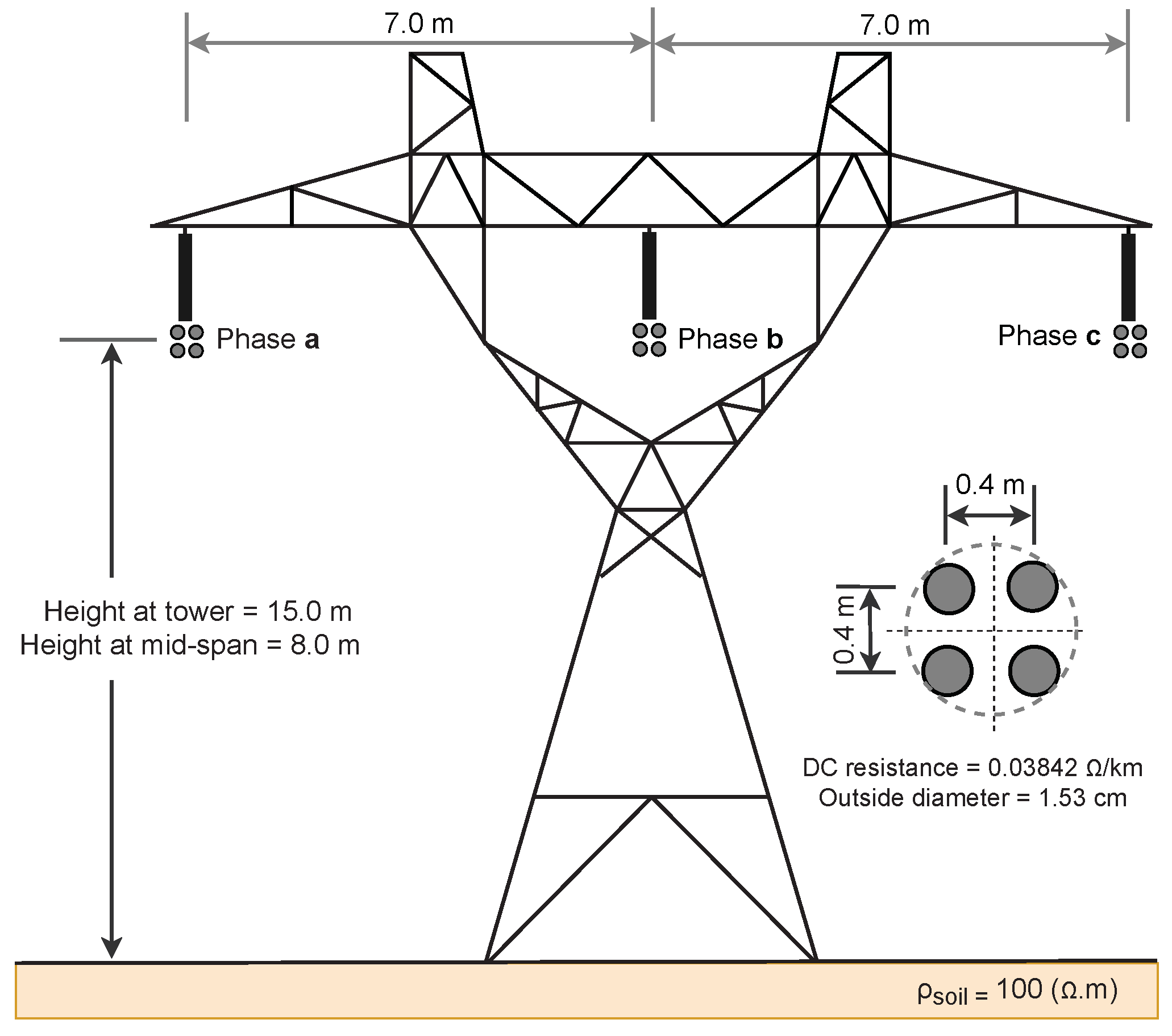
  • Computed the p.u.l. line parameters of the TL of Figure 5 using the PSCAD/EMTDC’s Line Constants Program;
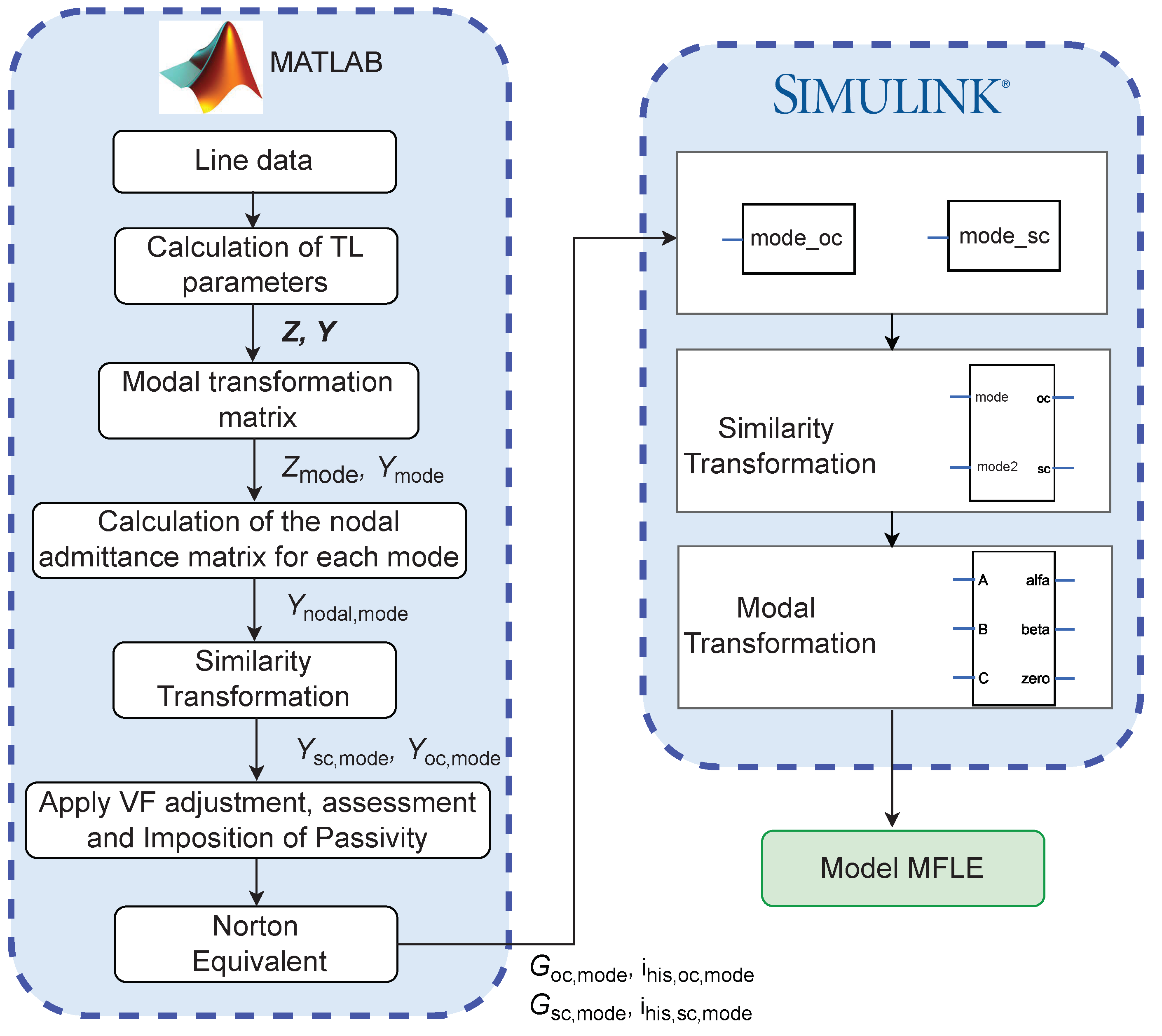
  • Simulated the TL using the proposed approach, implemented in Matlab/Simulink, as shown in Figure 4;
  • Simulated the TL using PSCAD/EMTDC’s ULM;
  • Compared the outputs of both models.
Figure 5. Three-phase transmission line geometry.
Energies 15 09302 g005
The flowchart of Figure 6 shows all the steps mentioned above, needed to implement the proposed model in MatLab’s Simulink (ver. 2021b).
One of the benefits of the proposed approach is that it provides accurate results when the time step is greater than the propagation delay of the TL. This is particularly useful in networks containing short and long lines because the time step of the entire network depends on the propagation delay of the shortest line. To show this advantage, we considered the TL of Figure 5 300 m long, resulting in a propagation delay of approximately 1 μ s. We show that the PFLE outputs accurate results in simulations with time steps greater than 1 μ s.

4.2. Fitting Procedure and Passivity Enforcement

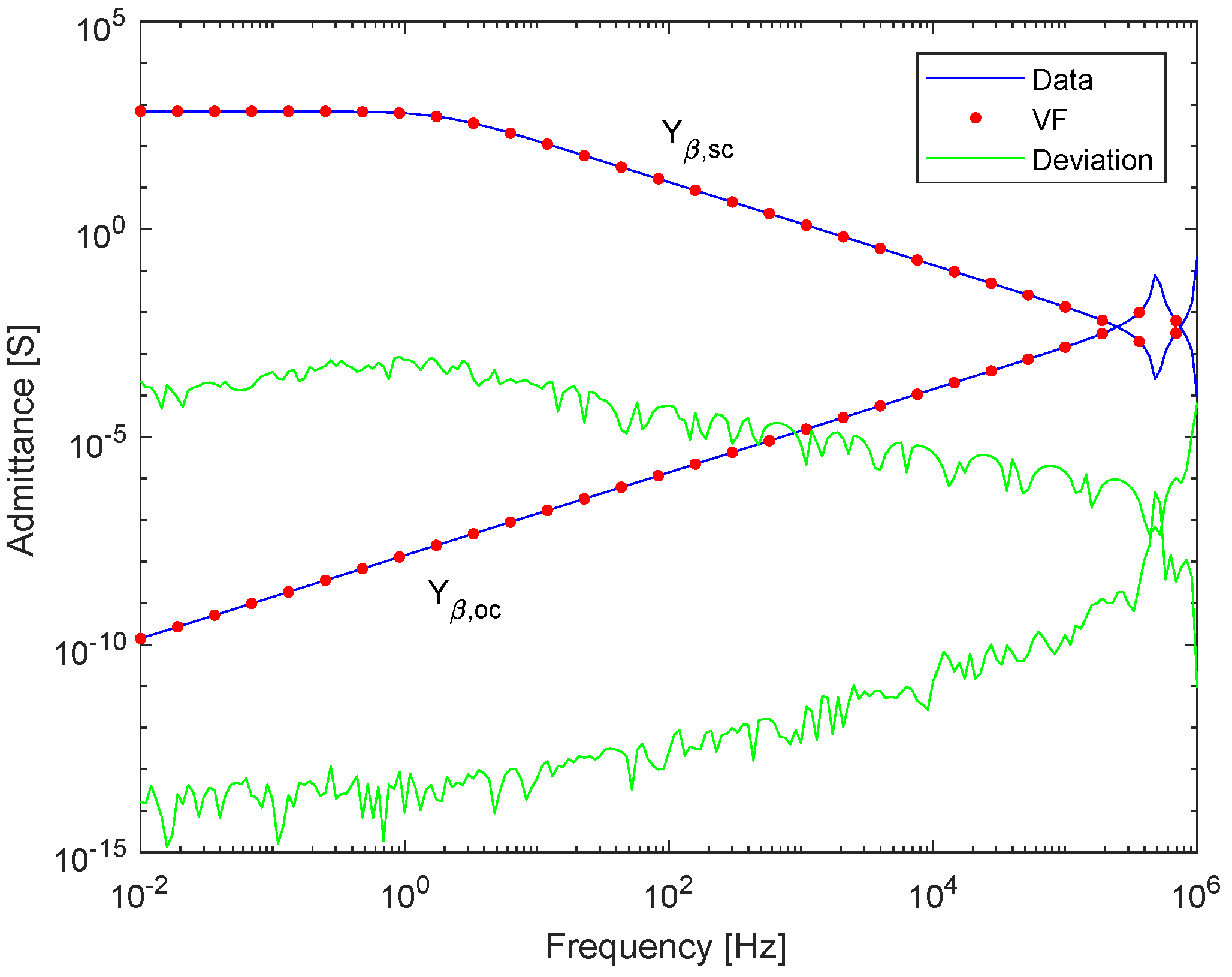
The TL of Figure 5 has three modes of propagation: α , β , and 0. Each mode is composed of an open-circuit and short-circuit nodal admittance.
We employed the VF routine [21] to fit the open-circuit and short-circuit admittances of each mode using twenty poles and five iterations. Passivity is independently enforced for each mode using the “RPdriver” routine [20]. Note that the “RPdriver” routine is applied to a frequency range that is twice the fitting frequency. Therefore, it is necessary to compute parameters up to 2 MHz.
Figure 7, Figure 8 and Figure 9 show the magnitude of the open-circuit and short-circuit nodal admittance of each mode (solid blue line), the fitted rational function after enforcing passivity (dotted red line), and the deviation between them (solid green line). Note that the deviation curve has a behavior similar to the data because the weight used in the fitting is inversely proportional to the magnitude of the data. This weighting scheme allows the accurate fitting of small and large values.
The number of poles required to fit a given function usually depends on the number of peaks present in the curve. The number of peaks in the frequency range of power systems transients increases with the length of the line. As a result, short lines require fewer poles to achieve a certain level of accuracy. This paper shows that the proposed model outputs accurate results in the simulation of short lines even when the time step of the simulation is larger than the propagation delay of the TL.
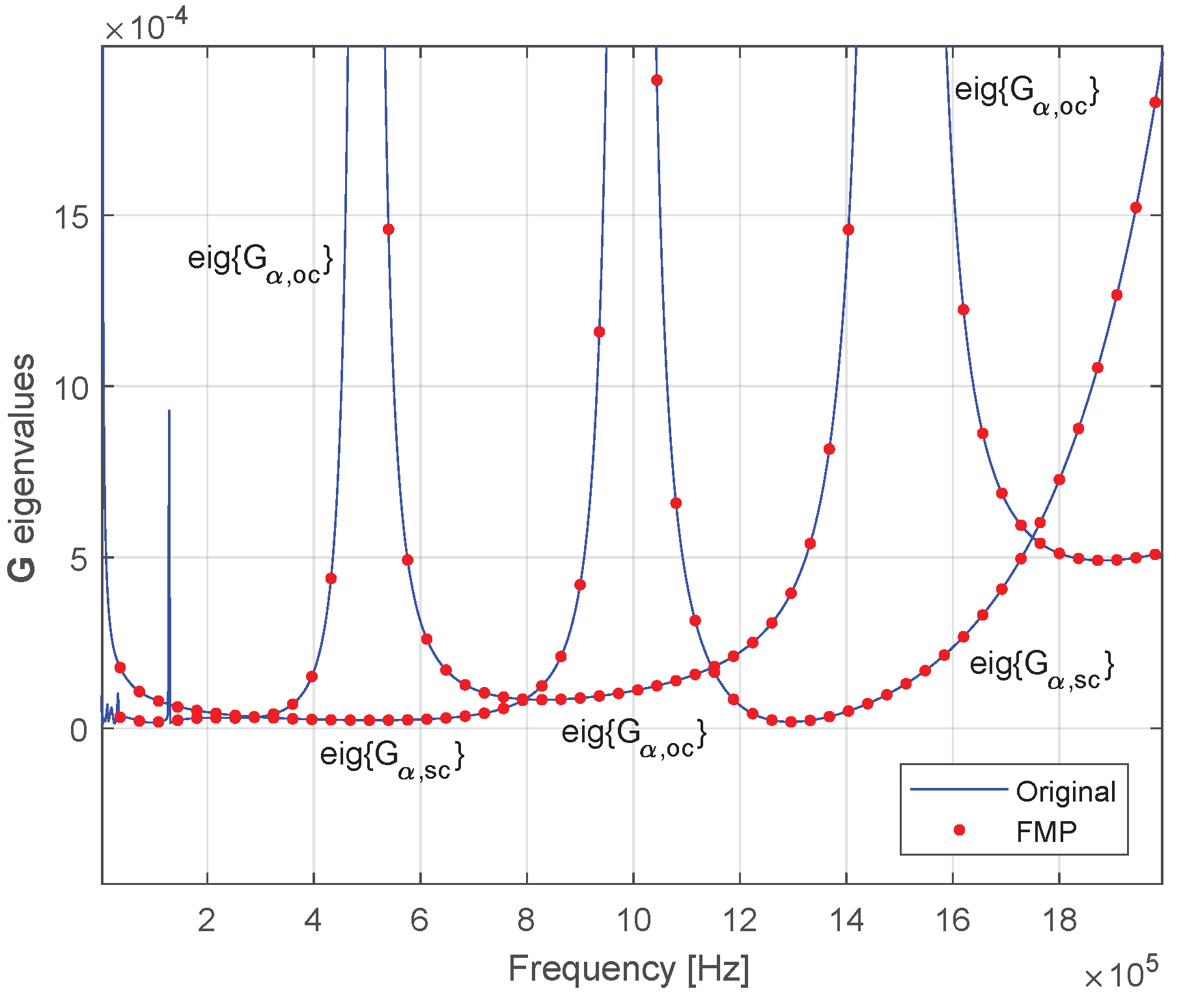
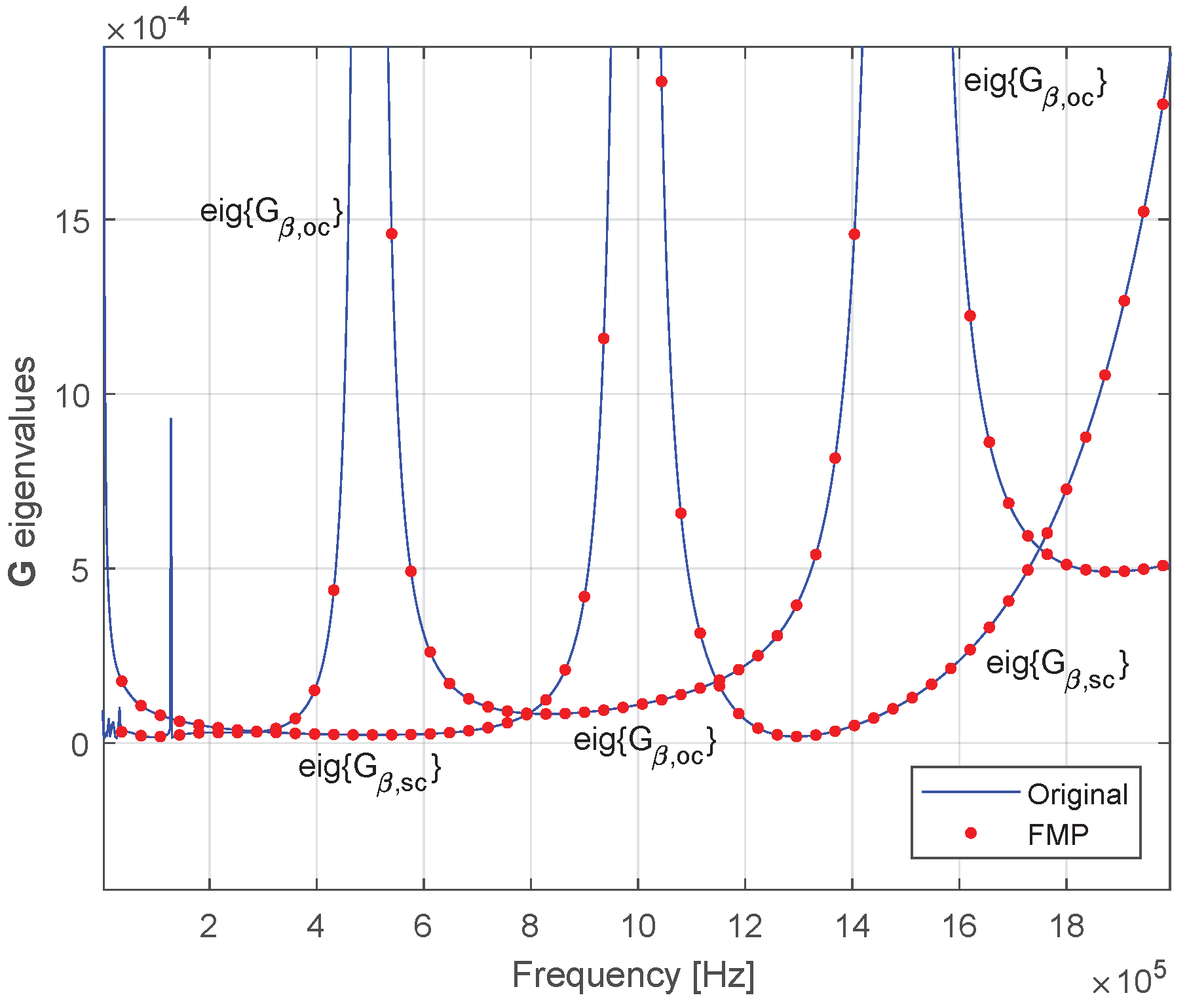
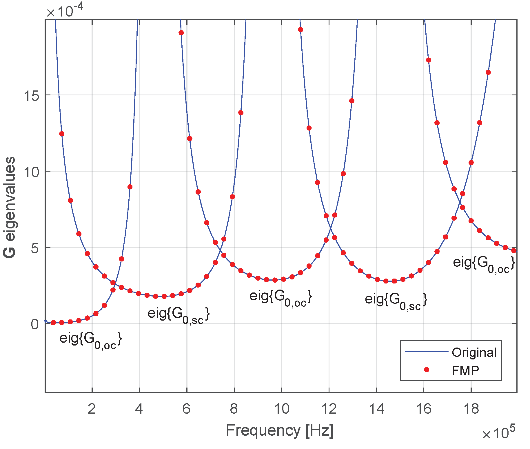
A Norton equivalent circuit is considered passive when the eigenvalues of the real part of the open-circuit nodal admittance Y oc , mk and short-circuit nodal admittance Y sc , mk are positive for all frequencies [8,22].
Figure 10, Figure 11 and Figure 12 show that the eigenvalues of the open-circuit and short-circuit conductances of each mode are positive after passivity is enforced.

4.3. Open-Circuit, Capacitive Load, and Single-Phase Fault

4.3.1. Simulation Layout

Figure 13 shows the TL of Figure 5 when one of its terminals is energized at 0 s, and the other terminal is
1.
Left open-circuited when the line is energized;
2.
Connected to a capacitive load at 4 ms;
3.
A single-phase fault occurs at 8 ms.
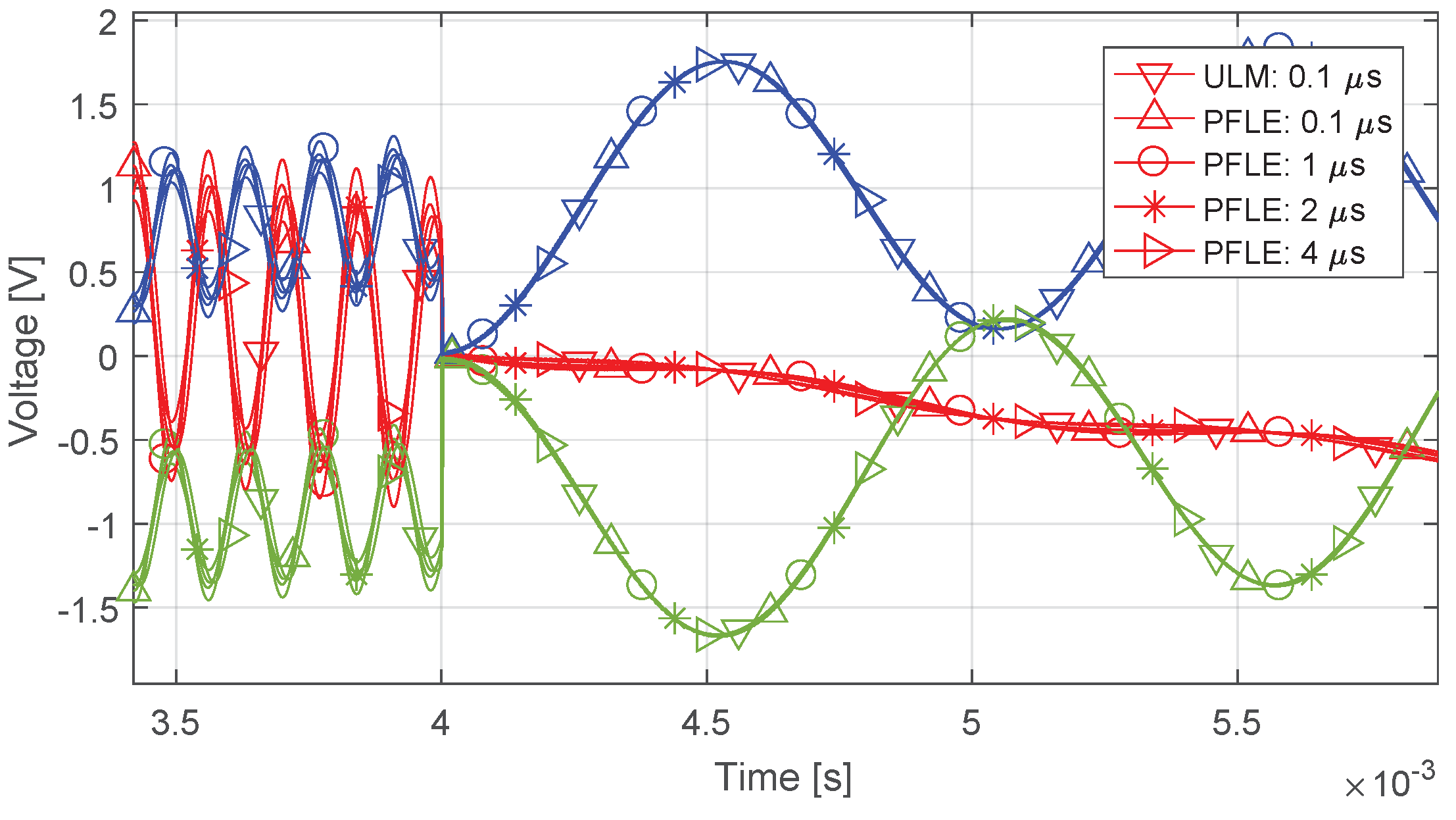
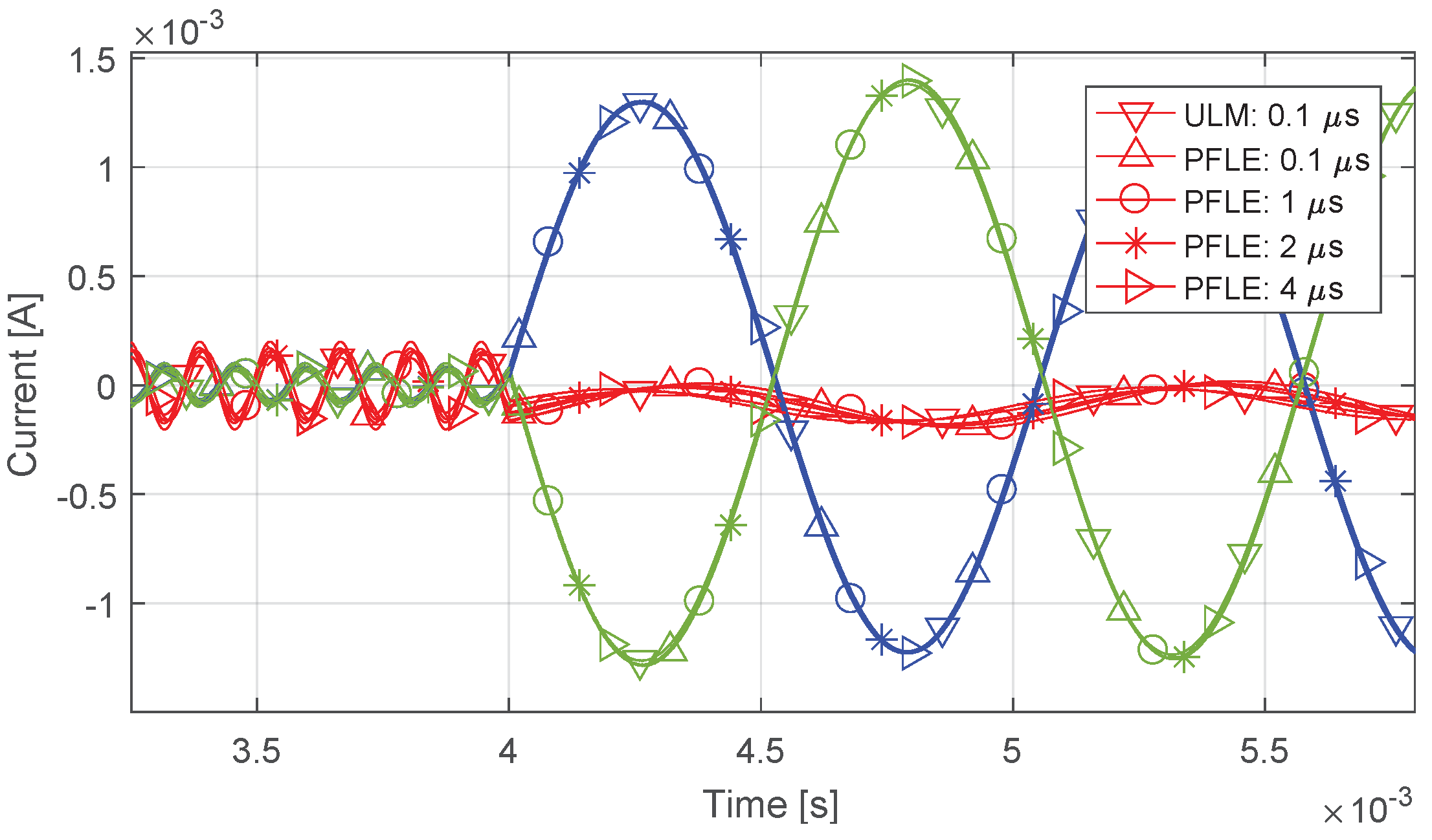
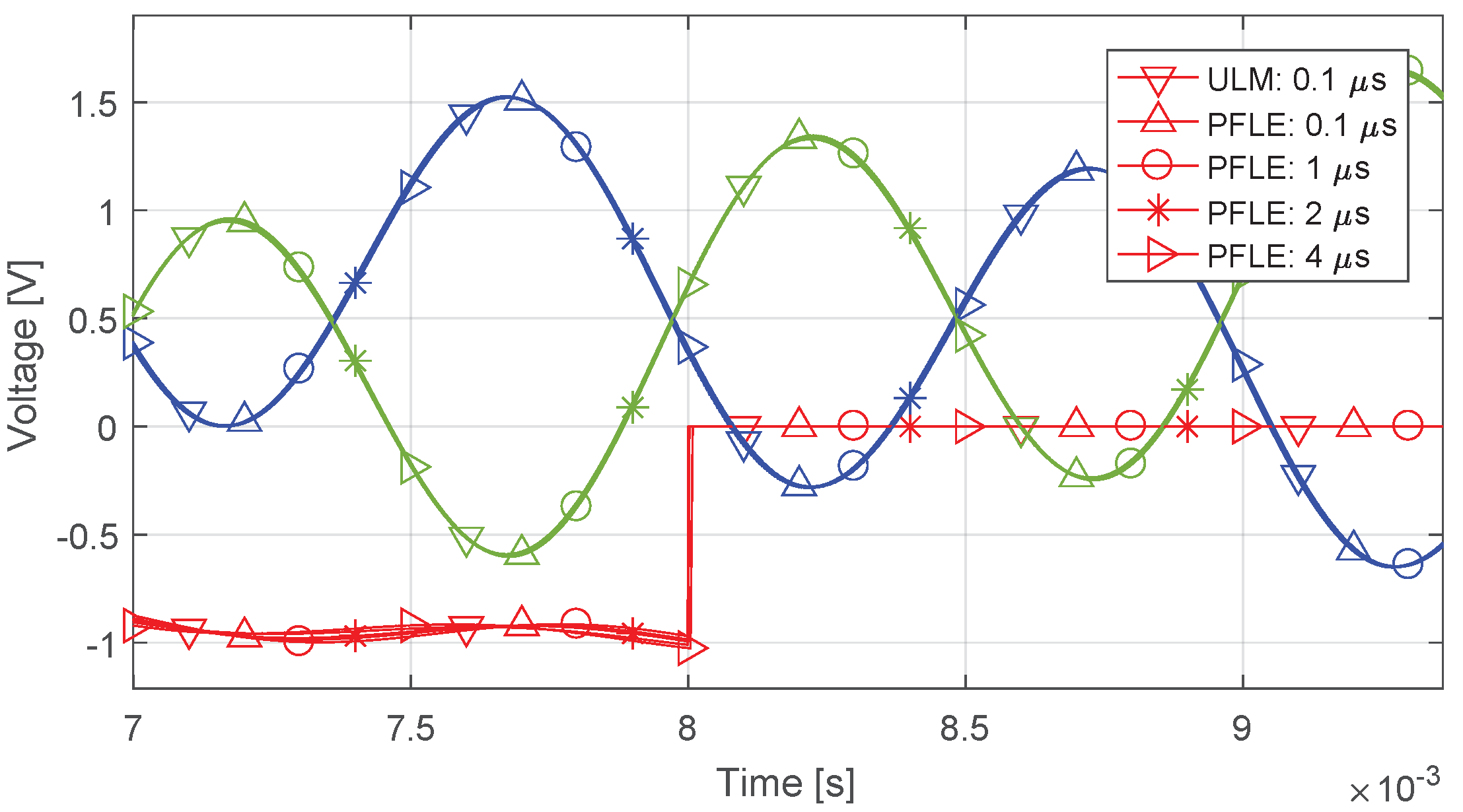
We compared the results obtained by the proposed approach (labeled as PFLE) to those obtained by PSCAD’s ULM. To show the advantages of the proposed approach, the simulations were performed considering different time steps.

4.3.2. Results

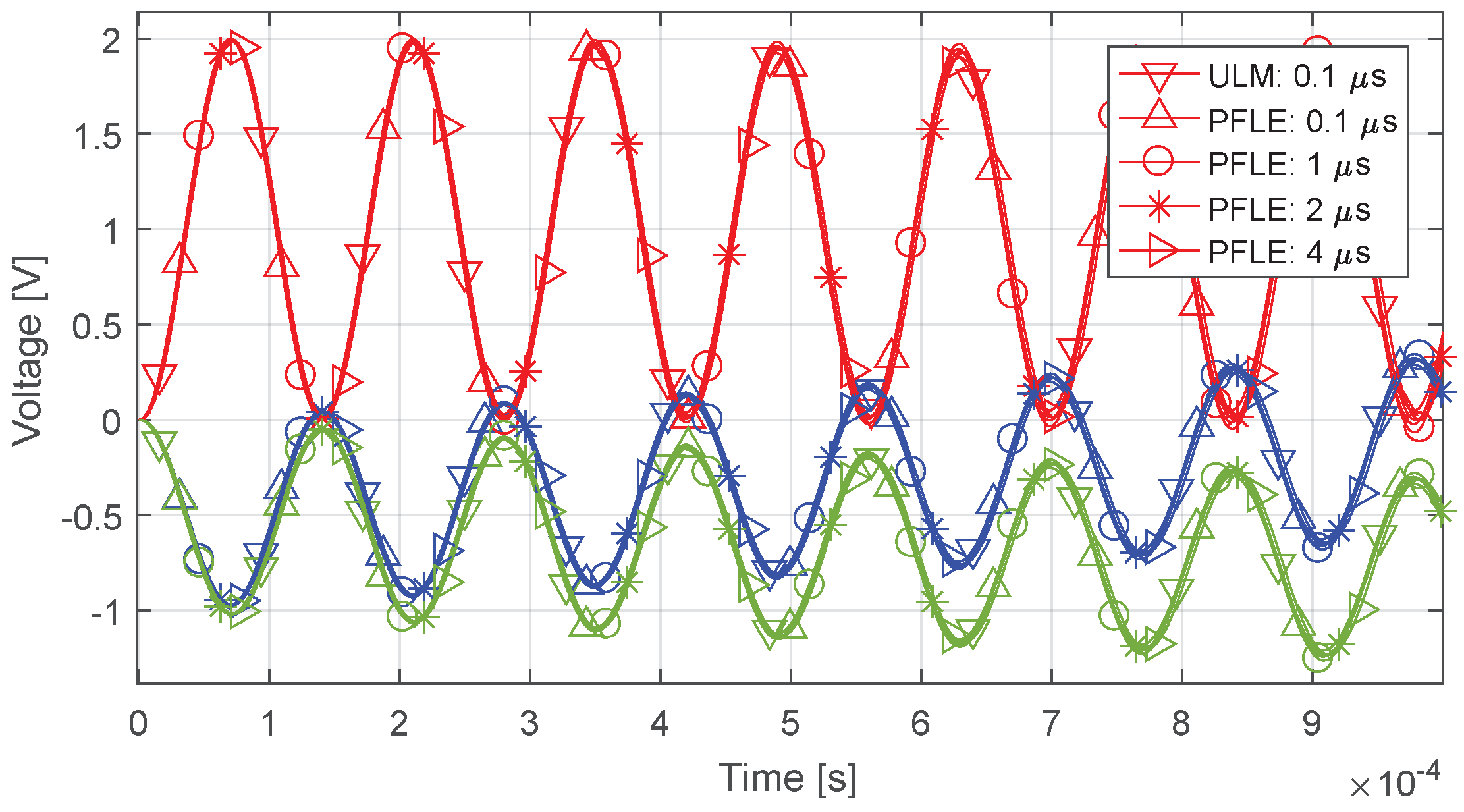
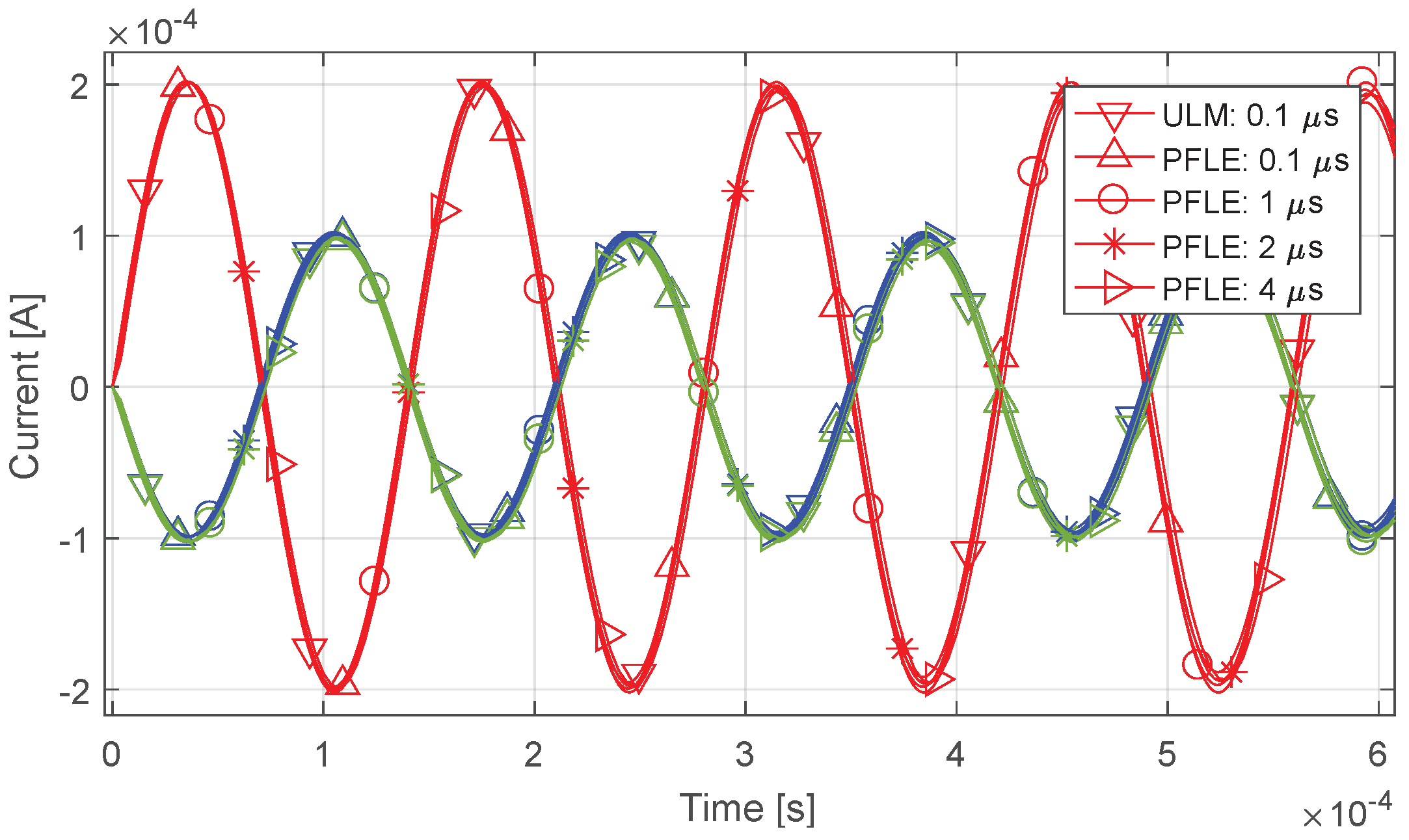
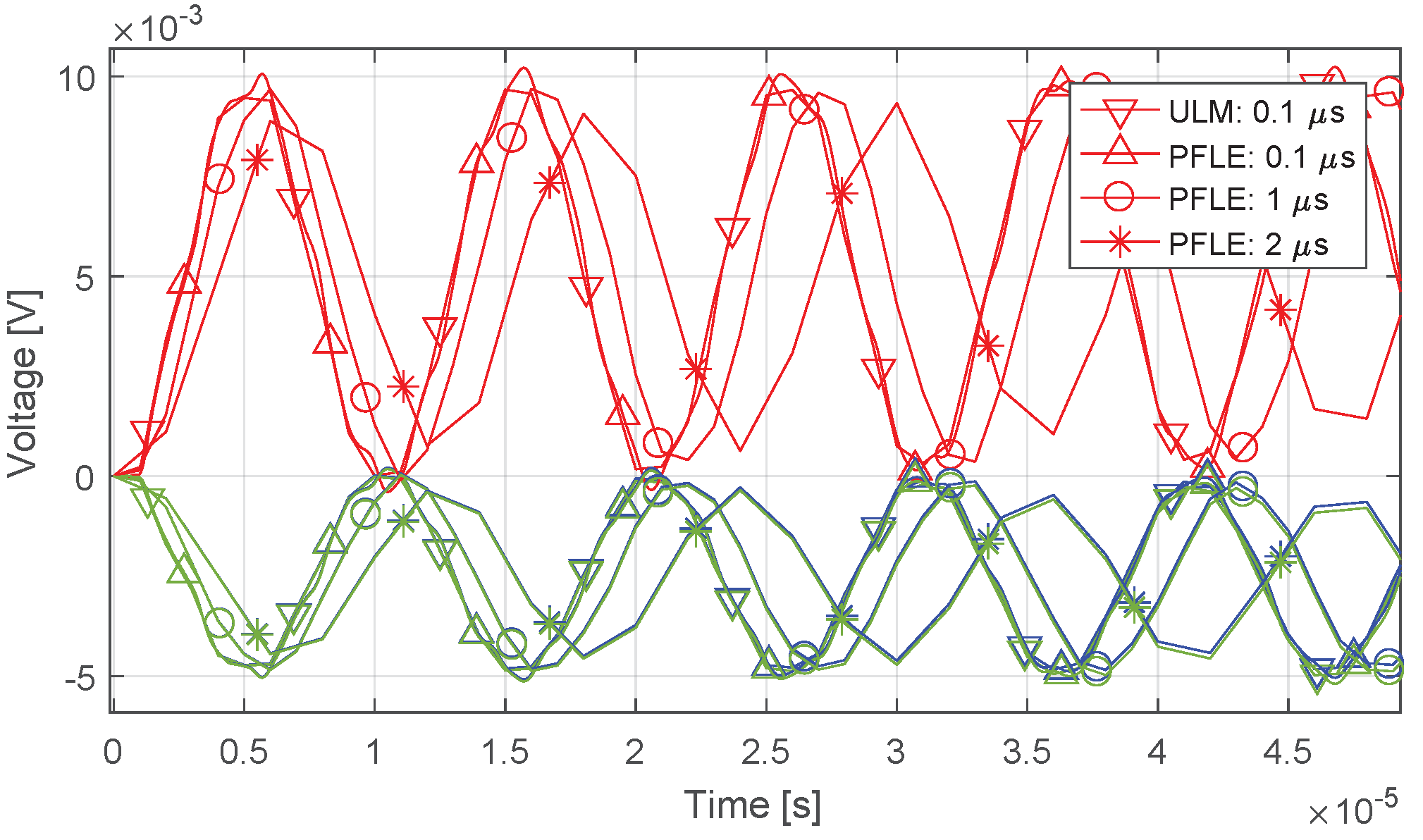
Results show that the proposed approach outputs accurate results even when the time step is four times the propagation delay of the TL. In contrast, the maximum integration time step that the ULM supports is equal to the propagation delay of the TL, which is approximately 1 μ s. This requirement must be met for all line models based on the method of characteristics. We use a time step equal to 1/10 of the propagation delay of the TL to compute results using the ULM.
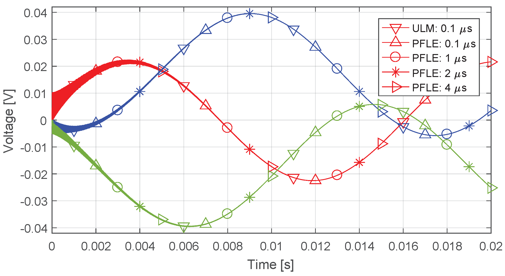
In all simulations, the red, blue, and green curves represent phases A, B, and C, respectively. The results are organized as follows:
1.
Figure 14 and Figure 15 show, respectively, the voltages at the receiving terminal and the currents at the sending terminal during line energization;
2.
Figure 16 and Figure 17 show, respectively, the voltages at the receiving terminal and the currents at the sending terminal when the capacitive load is connected;
3.
Figure 18 and Figure 19 show, respectively, the voltages at the receiving terminal and the currents at the sending terminal when a single-phase fault occurs at 8 ms.
Figure 14, Figure 15, Figure 16, Figure 17, Figure 18 and Figure 19 show that the PFLE outputs accurate results with time steps greater than the propagation delay of the TL. This can greatly reduce execution times in the simulation of large complex networks where the time step is limited to the propagation delay of the shortest line when TL models based on the methods of characteristics are used.

4.4. Line Energization

4.4.1. Simulation Layout

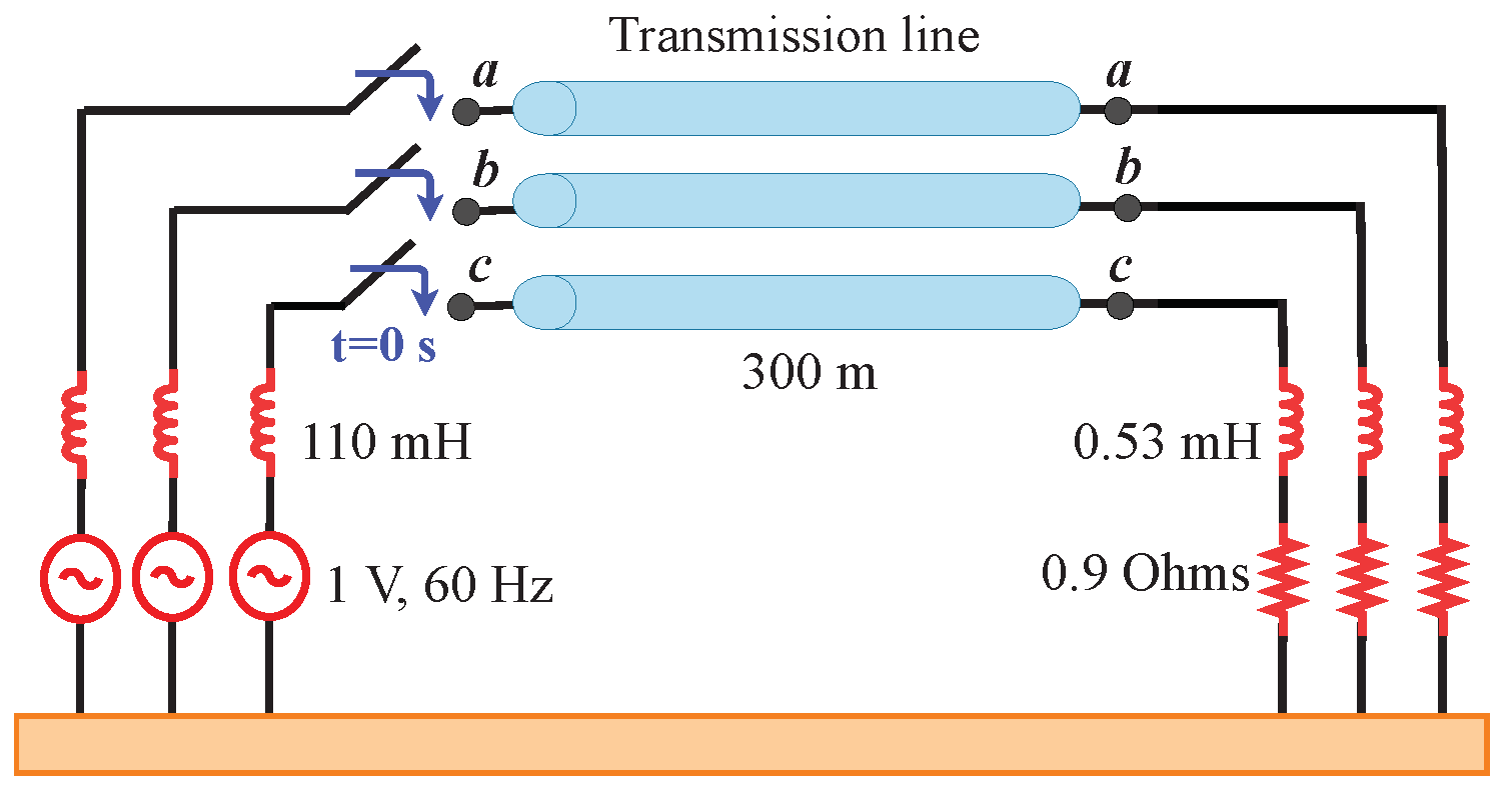
Figure 20 shows the TL of Figure 5 when one of its terminals is energized at 0 s and the other terminal is connected to a resistive-inductive load.

4.4.2. Results

Figure 21 and Figure 22 compare the voltages at the receiving terminal simulated with the proposed approach (labeled as PFLE) and PSCAD’s ULM for several time steps. Figure 21 shows the transient voltages right after the line is energized, and Figure 22 shows the voltages after the first high-frequency voltages disappear. Note that using a time step greater than the propagation delay of the TL causes a small delay during the first high-frequency oscillations, which disappears as the TL reaches steady-state conditions, as shown in Figure 22.
Figure 23 shows the currents at the sending terminal of the TL. Note that the proposed approach agrees with the ULM for all time steps.
The execution time of a simulation depends on the time required to solve a single time step and the total number of time steps in the simulation. Reducing the average time to solve one time step is possible through optimization techniques and lightweight models. However, the most effective way of reducing the execution time of simulation is by reducing the total number of time steps that need to be computed. TL models based on the method of characteristics are limited to time steps equal to the propagation delay of the shortest TL in the network. The proposed approach supports time steps greater than the propagation delay of the shortest TL without compromising accuracy. Our results show that the proposed approach outputs accurate results even with time steps that are four times the propagation delay of the shortest TL, resulting in execution times that are up to 400% faster.

4.5. Error

Section 4.3.2 and Section 4.4.2 show the results obtained by implementing the proposed approach, the PFLE, in MatLab’s Simulink. We measure the error of the PFLE using the normalized root-mean-square deviation (NRMSD), which is given by
NRMSD = 1 N i = 1 N y P M , i y ULM 2 max { y ULM } min { y ULM }
where N is the number of points of y.
In all simulations, we compare the results obtained by the PFLE to the results obtained by the ULM when the time step is 1/10 of the propagation delay of the TL (1 μ s). We use PSCAD/EMTDC’s ULM as a reference model because this model is widely accepted in technical literature and professional software due to its accuracy and numerical stability. The ULM computes results directly in the phase domain and time domain while considering the frequency dependence and distributed nature of line parameters.
Our numerical comparisons are organized as follows:

5. Conclusions

In this paper, we propose an alternative frequency-dependent transmission line (TL) model based on the folded line equivalent (FLE) line model to represent three-phase TLs. The proposed approach uses a circuit representation of Clarke’s matrix to transform parameters from the phase domain to the mode domain. Then, instead of using the transformation matrix proposed in [8], we use a new transformation matrix to transform parameters from the mode domain to the FLE domain. The proposed matrix allows the proposed model to be implemented in simulation software using ideal transformers. The open-circuit and short-circuit contributions of the proposed approach are represented in simulation software using Norton equivalent circuits. We implement the proposed approach in MatLab’s Simulink multidomain simulation software.
Traditional TL models based on the method of characteristics can only run in simulations where the time step is equal to or less than the propagation delay of the shortest TL in the network. The main advantage of the proposed approach is that it can run on simulations where the step size is greater than the propagation time of the TL without compromising accuracy. Figure 14 through Figure 23 show good agreement between the results obtained with the ULM and the PFLE. Furthermore, they show that the PFLE provides accurate results even when the time step is four times greater than the propagation delay of the TL. Table 1, Table 2, Table 3 and Table 4 show that the NRMSD of the results obtained by the PFLE, when compared to the results obtained by the ULM with a time step of 1/10 of the propagation delay of the TL, is less than 0.005. These results prove that the proposed model outputs accurate results in simulations where the time step is 10%, 100%, 200%, and 400% of the propagation time of the TL.

Author Contributions

Conceptualization, J.S.L.C., S.K., L.T., P.T.C. and J.P.F.; methodology, J.S.L.C. and L.T.; software, J.S.L.C. and L.T.; validation, J.S.L.C. and L.T.; formal analysis, J.S.L.C., L.T. and P.T.C.; investigation, J.S.L.C. and L.T.; writing—original draft preparation, J.S.L.C., L.T. and P.T.C.; visualization, J.S.L.C. and L.T.; supervision, P.T.C., S.K. and J.P.F.; project administration, S.K. and J.P.F.; funding, S.K. All authors have read and agreed to the published version of the manuscript.

Funding

This work was funded by the Coordenação de Aperfeiçoamento de Pessoal de Nível Superior—Finance code 001, the São Paulo Research Foundation grant: 2021/06157-5, and the Centro de Pesquisa e Desenvolvimento em Telecomunicações.

Institutional Review Board Statement

Not applicable.

Informed Consent Statement

Not applicable.

Data Availability Statement

Not applicable.

Conflicts of Interest

The authors declare no conflict of interest.

Abbreviations

The following abbreviations are used in this manuscript:
TLTransmission line
ATP-EMTPAlternative Transient Program-Electromagnetic Transients Program
ULMUniversal Line Model
PSCADPower Systems Computer Aided Design
EMRP-RVElectromagnetic Transients Program-Restructured Version
FLEFolded Line Equivalent
VFVector Fitting
p.u.l.per unit length
FMPFast Modal Perturbation
PFLEProposed Folded Line Equivalent

References

  1. Marti, J.R. Accurate Modeling of Frequency-Dependent Transmission Lines in Electromagnetic Transient Simulations. IEEE Power Eng. Rev. 1982, 2, 29–30. [Google Scholar] [CrossRef]
  2. Laurent Dubé European EMTP-ATP Users Group e.V. Users Guide to Models in ATP. April 1999. Available online: https://pdfcoffee.com/users-guide-to-models-in-atp-acknowledgments-pdf-free.html (accessed on 30 January 2022).
  3. Morched, A.S.; Gustavsen, B.; Tartibi, M. A universal model for accurate calculation of electromagnetic transients on overhead lines and underground cables. IEEE Trans. Power Deliv. 1999, 14, 1032–1037. [Google Scholar] [CrossRef]
  4. Manitoba HVDC Research Centre Inc. PSCAD-EMTDC Version 4.5 The Professional’s Tool for Electromagnetic Transients Simulation; Manitoba HVDC Research Centre, Inc.: Winnipeg, MB, Canada, 2008. [Google Scholar]
  5. EMTP-RV. 2021. Available online: http://emtp.com/ (accessed on 1 February 2022).
  6. Dommel, H.W. Digital Computer Solution of Electromagnetic Transients in Single-and Multiphase Networks. IEEE Trans. Power Appar. Syst. 1969, PAS-88, 388–399. [Google Scholar] [CrossRef]
  7. De Silva, H.M.J.; Kariyawasam, K.K.M.A.; Gole, A.M.; Nordstrom, J.E. Accurate time domain simulation of frequency dependent transmission line models for large time steps. In Proceedings of the International Conference on Power Systems Transients (IPST), Vancouver, BC, Canada, 18–20 July 2013. [Google Scholar]
  8. Gustavsen, B.; Semlyen, A. Admittance-Based Modeling of Transmission Lines by a Folded Line Equivalent. IEEE Trans. Power Deliv. 2009, 24, 231–239. [Google Scholar] [CrossRef]
  9. Gustavsen, B.; Semlyen, A. Rational approximation of frequency domain responses by vector fitting. IEEE Trans. Power Deliv. 1999, 14, 1052–1061. [Google Scholar] [CrossRef] [Green Version]
  10. Gustavsen, B. Improving the pole relocating properties of vector fitting. IEEE Trans. Power Deliv. 2006, 21, 1587–1592. [Google Scholar] [CrossRef]
  11. Simscape Electrical User’s Guide (Specialized Power Systems). Hydro-Quebec and Math Works. 2022. Available online: https://www.mathworks.com/help/physmod/sps/ (accessed on 1 February 2022).
  12. Morched, A.S.; Ottevangers, J.H.; Marti, L. Multi-port frequency dependent network equivalents for the EMTP. IEEE Trans. Power Deliv. 1993, 8, 1402–1412. [Google Scholar] [CrossRef]
  13. Semlyen, A.; Gustavsen, B. Phase-Domain Transmission-Line Modeling With Enforcement of Symmetry Via The Propagated Characteristic Admittance Matrix. IEEE Trans. Power Deliv. 2012, 27, 626–631. [Google Scholar] [CrossRef]
  14. Gustavsen, B. Validation of frequency-dependent transmission line models. IEEE Trans. Power Deliv. 2005, 20, 925–933. [Google Scholar] [CrossRef]
  15. Tavares, M.C.; Pissolato, J.; Portela, C.M. New mode domain multiphase transmission line model-transformation matrix modeling. In Proceedings of the POWERCON, International Conference on Power System Technology, Proceedings (Cat. No.98EX151), Beijing, China, 18–21 August 1998; Volume 2, pp. 855–859. [Google Scholar] [CrossRef]
  16. Colqui, J.S.L.; Timaná, L.; Caballero, P.T.; Kurokawa, S.; Filho, J.P. Implementation of modal domain transmission line models in the ATP software. IEEE Access 2022, 10, 15924–15934. [Google Scholar] [CrossRef]
  17. Gustavsen, B.; De Silva, H.M.J. Inclusion of Rational Models in an Electromagnetic Transients Program: Y-Parameters, Z-Parameters, S-Parameters, Transfer Functions. IEEE Trans. Power Deliv. 2013, 28, 1164–1174. [Google Scholar] [CrossRef]
  18. Gustavsen, B. Computer code for rational approximation of frequency dependent admittance matrices. IEEE Trans. Power Deliv. 2002, 17, 1093–1098. [Google Scholar] [CrossRef]
  19. Gustavsen, B. Fast Passivity Enforcement for Pole-Residue Models by Perturbation of Residue Matrix Eigenvalues. IEEE Trans. Power Deliv. 2008, 23, 2278–2285. [Google Scholar] [CrossRef]
  20. Gustavsen, B. Matrix Fitting Toolbox (User’s Guide and Reference); SINTEF Energy Research: Trondheim, Norway, 2009. [Google Scholar]
  21. Gustavsen, B. User’s Guide for Vectfit3.m (Fast Relaxed Vector Fitting); SINTEF Energy Research: Trondheim, Norway, 2008. [Google Scholar]
  22. Boyd, S.; Chua, L.O. On the passivity criterion for LTI n-ports. Circuit Theory Appl. 1982, 10, 323–333. [Google Scholar] [CrossRef]
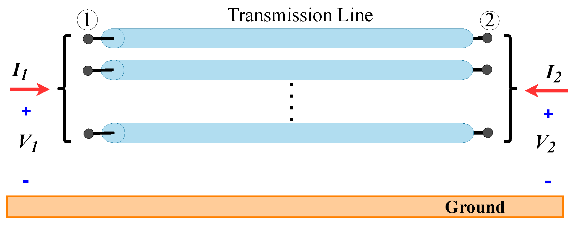
Figure 1. Multiconductor transmission line.
Energies 15 09302 g001
Figure 2. Representation of a three-phase transmission line in the mode domain: abc α β 0 abc.
Energies 15 09302 g002
Figure 3. Mode representation for the proposed FLE (PFLE) model.
Energies 15 09302 g003
Figure 4. Circuit representation of (a) Clarke’s matrix ( α β 0 transformation) and (b) the proposed FLE transformation matrix (FLE transformation).
Energies 15 09302 g004
Figure 6. Steps required to implement the PFLE in MatLab’s Simulink.
Energies 15 09302 g006
Figure 7. Fitting of the open-circuit admittance Y oc and short-circuit admittance Y sc of mode α .
Energies 15 09302 g007
Figure 8. Fitting of the open-circuit admittance Y oc and short-circuit admittance Y sc of mode β .
Energies 15 09302 g008
Figure 9. Fitting of the open-circuit admittance Y oc and short-circuit admittance Y sc of mode 0.
Energies 15 09302 g009
Figure 10. Eigenvalues of the nodal admittance matrix of mode α .
Energies 15 09302 g010
Figure 11. Eigenvalues of the nodal admittance matrix of mode β .
Energies 15 09302 g011
Figure 12. Eigenvalues of the nodal admittance matrix of mode 0.
Energies 15 09302 g012
Figure 13. Simulation configuration.
Energies 15 09302 g013
Figure 14. Voltage at the receiving end of the line when the line is energized.
Energies 15 09302 g014
Figure 15. Current at the sending end of the line when the line is energized.
Energies 15 09302 g015
Figure 16. Voltage at the receiving end of the line when the cable is connected.
Energies 15 09302 g016
Figure 17. Current at the sending end of the line when the cable is connected.
Energies 15 09302 g017
Figure 18. Voltage at the receiving end of the line after a single-phase fault occurs.
Energies 15 09302 g018
Figure 19. Current at the sending end of the line after a single-phase fault occurs.
Energies 15 09302 g019
Figure 20. Transmission line connected to a resistive-inductive load.
Energies 15 09302 g020
Figure 21. Voltages at the receiving terminal of the line right after it is energized.
Energies 15 09302 g021
Figure 22. Voltages at the receiving end of the line in the first 20 ms of the simulation.
Energies 15 09302 g022
Figure 23. Current at the sending terminal of the line.
Energies 15 09302 g023
Table 1. NRMSD of the voltage and current curves obtained with the PFLE with respect to the voltage and current curves obtained with the ULM and a time step of 1 μ s: Figure 14 and Figure 15.
VoltageCurrent
PhasesModel: Δ tNRMSDPhasesModel: Δ tNRMSD
1
(Figure 14)
PFLE: 0.1 μ s0.0041
(Figure 15)
PFLE: 0.1 μ s1 × 10 4
PFLE: 1 μ s0.003PFLE: 1 μ s3 × 10 4
PFLE: 2 μ s0.003PFLE: 2 μ s1 × 10 4
PFLE: 4 μ s0.005PFLE: 4 μ s2 × 10 4
2 and 3
(Figure 14)
PFLE: 0.1 μ s0.0052 and 3
(Figure 15)
PFLE: 0.1 μ s1 × 10 4
PFLE: 1 μ s0.003PFLE: 1 μ s2 × 10 4
PFLE: 2 μ s0.003PFLE: 2 μ s4 × 10 4
PFLE: 4 μ s0.005PFLE: 4 μ s1 × 10 4
Table 2. NRMSD of the voltage and current curves obtained with the PFLE with respect to the voltage and current curves obtained with the ULM and a time step of 1 μ s: Figure 16 and Figure 17.
VoltageCurrent
PhasesModel: Δ tNRMSDPhasesModel: Δ tNRMSD
1
(Figure 16)
PFLE 0.1 μ s0.0041
(Figure 17)
PFLE 0.1 μ s2 × 10 4
PFLE 1 μ s0.003PFLE 1 μ s3 × 10 4
PFLE 2 μ s0.003PFLE 2 μ s4 × 10 4
PFLE 4 μ s0.005PFLE 4 μ s1 × 10 4
2 and 3
(Figure 16)
20.0052 and 3
(Figure 17)
PFLE 0.1 μ s2 × 10 4
PFLE 1 μ s0.003PFLE 1 μ s1 × 10 4
PFLE 2 μ s0.003PFLE 2 μ s2 × 10 4
PFLE 4 μ s0.005PFLE 4 μ s3 × 10 4
Table 3. NRMSD of the voltage and current curves obtained with the PFLE with respect to the voltage and current curves obtained with the ULM and a time step of 1 μ s: Figure 18 and Figure 19.
VoltageCurrent
PhasesModel: Δ tNRMSDPhasesModel: Δ tNRMSD
1
(Figure 18)
PFLE 0.1 μ s0.0041
(Figure 19)
PFLE 0.1 μ s2 × 10 4
PFLE 1 μ s0.003PFLE 1 μ s3 × 10 4
PFLE 2 μ s0.003PFLE 2 μ s2 × 10 4
PFLE 4 μ s0.005PFLE 4 μ s1 × 10 4
2 and 3
(Figure 18)
20.0052 and 3
(Figure 19)
PFLE 0.1 μ s42 × 10 4
PFLE 1 μ s0.003PFLE 1 μ s1 × 10 4
PFLE 2 μ s0.003PFLE 2 μ s2 × 10 4
PFLE 4 μ s0.005PFLE 4 μ s4 × 10 4
Table 4. NRMSD of the voltage and current curves obtained with the PFLE with respect to the voltage and current curves obtained with the ULM and a time step of 1 μ s: Figure 22 and Figure 23.
VoltageCurrent
PhasesModelNRMSDPhasesModelNRMSD
1
(Figure 22)
PFLE 0.1 μ s0.0041
(Figure 23)
PFLE 0.1 μ s3 × 10 4
PFLE 1 μ s0.003PFLE 1 μ s3 × 10 4
PFLE 2 μ s0.003PFLE 2 μ s1 × 10 4
PFLE 4 μ s0.005PFLE 4 μ s1 × 10 4
2 and 3
(Figure 22)
PFLE 0.1 μ s0.0052 and 3
(Figure 23)
PFLE 0.1 μ s2 × 10 4
PFLE 1 μ s0.003PFLE 1 μ s2 × 10 4
PFLE 2 μ s0.003PFLE 2 μ s1 × 10 4
PFLE 4 μ s0.005PFLE 4 μ s4 × 10 4
Publisher’s Note: MDPI stays neutral with regard to jurisdictional claims in published maps and institutional affiliations.