
Analysis of Using Soot Application in the Processing of Zinc-Bearing Waste Materials
by
 , , , ,
Albert Smalcerz
1,
Szymon Ptak
2,*,
Jerzy Łabaj
3,
Marzena Półka
2,
Adam Kula
4 and
Leszek Blacha
3 1
Department of Industrial Informatics, Faculty of Materials Science, Silesian University of Technology, Krasinskiego 8, 40-019 Katowice, Poland
2
Main School of Fire Service, 52/54 Słowackiego St., 01-629 Warsaw, Poland
3
Department of Metallurgy and Recycling, Faculty of Materials Science, Silesian University of Technology, Krasinskiego 8, 40-019 Katowice, Poland
4
Joint Doctorate School, Department of Industrial Informatics, Faculty of Materials Science, Silesian University of Technology, Krasinskiego 8, 40-019 Katowice, Poland
*
Author to whom correspondence should be addressed.
Energies 2022, 15(21), 7969; https://doi.org/10.3390/en15217969
Submission received: 16 September 2022
/
Revised: 19 October 2022
/
Accepted: 25 October 2022
/
Published: 27 October 2022
(This article belongs to the Topic Advanced Processes in Metallurgical Technologies)
Abstract
:In metallurgical processes, coke is used, among other materials, in order to implement the process of removing zinc from waste by reduction and evaporation. Due to the implemented de-carbonization policy, we are dealing with an increase in costs and decreasing availability of coke, which leads to an intensive search for other possibilities for conducting the process, which may generate a fire and explosion hazard in the technological process. This article analyzes the possibility of using soot in the process of reducing the zinc content in deposited metallurgical waste, taking into account the issue of fire and explosion safety. The results of the research proved the possibility of the safe use of the reductor, which is soot and anthracite, as a material replacing coke in pyrometallurgical processes.
1. Introduction
1.1. Pyrometallurgical Processes
Recent research has shown the possibility of raw material management. Fine-grained carbon-bearing waste materials generated in the processes of hard coal enrichment, in coking technologies, or in the chemical industry have the potential to be re-used. They are most often used as components of coal blends and energy fuels or as alternative fuels for applications in strictly defined technological processes. In addition, the metallurgical industry, interested in obtaining metals from primary and waste materials in pyrometallurgical technologies, seeks alternative carbon-bearing additives that can replace coke. This interest is mainly due to economic aspects, as the price of this basic raw material additive has been growing significantly for several years. This is due to a significant decline in hard coal mining in the EU. For example, in 2000, the extraction of this raw material in the EU was equal to 169 million Mg and was further reduced to 56 million Mg in 2020 [1]. In 1990, 13 Member States of the present EU produced hard coal; in 2019, there were only two countries, i.e., Poland and Czechia.
Limiting coal extraction also results in a reduction in the amount of produced coke and, as previously noted, it is the basic carbon-bearing material used in pyrometallurgical technologies for obtaining metals. Its role in these processes should be considered in two aspects, i.e., energetic and chemical. In the first case, it is the role of coke as a fuel, as a result of its combustion, to provide the heat necessary to raise the temperature of the charge in the metallurgical unit, to cause its melting, and to facilitate a series of endothermic reactions necessary for the proper implementation of a given technological process [2]. The chemical aspects of using coke in the discussed processes are related to the course of the reduction reaction, e.g., of the metal oxide compounds contained in the charge. The basic reducer enabling their course is carbon monoxide, formed in metallurgical aggregates as a result of the Boudouard reaction. The amount of coke and coke breeze consumed in pyrometallurgical processes is very diverse, which is illustrated by the data presented in Table 1.
The data presented in Table 1 shows how significant amounts of coke and coke breeze are used in the pyrometallurgical processes of obtaining metals. This indicates the advisability of looking for other, cheaper, carbon-bearing materials as an alternative to these two basic carbon carriers in metallurgical processes.
Taking into account the existing deposits of carbon waste materials, mainly from coal enrichment processes, coking processes, and the chemical industry—the use of which in the power industry is very limited—it is advisable to conduct research on their use in other industries [3,4,5,6,7,8,9,10].
The paper presents the results of research on the processing of waste zinc-bearing materials in a rotary kiln with the use of soot as a carbon-bearing material, which is a waste generated in the chemical industry.
The effectiveness of the use of fine-grained carbon-bearing materials in metallurgical aggregates depends on their energetic parameters, reactivity, and the form in which it occurs. In the majority of pyrometallurgical technologies for obtaining metals from both primary and secondary raw materials, the process is based on the countercurrent flow of feed materials and gases. A too-fine charge may float from the aggregate or constitute a barrier preventing gas flow. Often, agglomeration techniques are used to adapt the form of the material to that required for a given metallurgical aggregate to fulfill its role depending on the technological needs.
1.2. Waelz Process
The basic technology for the processing of waste zinc-bearing materials, including sludge from zinc electrolysis and steel dust, is the rotary process known as the Waelz process, carried out in rotary kilns. This technology is used in over 30 plants worldwide. It is assumed that up to 80% of utilized steel dust is processed in this way [11].
In recent years, this technology has been improved in terms of energy (coke) consumption and gaseous emission control. The European Waelz plants fulfill the requirements of the best available technology for environmental protection. The related Waelz process is notified in the BREF notes of the European Community [9].
The discussed zinc recovery process takes place by reducing the compounds contained in the charge [12,13]. The operating temperature of the continuous furnace is usually 1473 K. Inside the furnace, the charge is initially dried and then heated to the required temperature by a countercurrent flow of exhaust gas. Depending on the angle of inclination of the furnace, its length, and rotational speed, the residence time of the charge in the furnace ranges from 4 to 6 h. In a highly reducing atmosphere, zinc is converted to its elemental form and evaporated to the gas phase, and then oxidized with excess air. Zinc oxide is removed from the furnace along with the flue gas stream and released in the filtration devices. The process gas purification system usually consists of a settling chamber, a cooling section, and an electrostatic precipitator, often combined with a bag filter. The slag obtained in the furnace usually contains up to 4 wt.% Zn and 30–45 wt.% Fe. This is continuously discharged from the hot end of the furnace and directed to the cooling process. The so-called crude zinc oxide, which is the basic product of the Waelz process, contains on average 45–55 wt.% Zn; 4–10 wt.% Pb; 2–6 wt.% Fe. It is processed in shaft furnaces (ISF—Imperial Smelting Furnace) or hydrometallurgical technology. The diagram of the breakthrough process is presented in Figure 1.
Due to the temperature distribution, three zones can be distinguished in the fusing furnace, as shown in Figure 2.
In the first zone, the process of water removal as well as heating and homogenization of the feed materials takes place. In this zone, the charge temperature ranges up to 773 K. In the second zone, calcination reaction takes place, i.e., decomposition of carbonates in the temperature range from 773 to 1173 K. In the third zone, called the reaction zone, the main processes related to the reduction of metal oxides take place, including the zinc. The temperature in this zone ranges from 1173 to 1573 K. The basic reactions taking place in the various zones of the furnace are presented below [12].
Zone 1:
H2O => H2O(g)
Zone 2:
C + O2 => CO2
C + CO2 => 2CO
CaCO3 => CaO + CO2
Fe2O3 + CO => 2FeO + CO2
Fe3O4 + CO => 3FeO + CO2
Zone 3:
ZnO + CO => Zn(g) + CO2
FeO + CO => Fe + CO2
Fe3O4·ZnO + CO2 => 3FeO + ZnO + CO2
ZnO·SiO2 + CO => Zn(g) + SiO2 + CO2
Additionally, depending on the flux used in the process, the following reaction takes place:
2FeO + SiO2 => Fe2SiO4
Reactions (2) and (3) show the actual role of carbon in the discussed technological process.
1.3. Fire and Explosion Safety
Any combustible material can ignite, posing a fire hazard. The greater the fragmentation of the material, the greater the risk. This is due to a more favorable total surface-area-to-volume ratio of the combustible particle. A larger particle surface means more favorable heat exchange conditions with the environment, which affects the rate of thermal decomposition and the rate of the particle combustion reaction. In accordance with [14], it is assumed that the material fragmentation below 500 μm meets the definition of flammable dust, which causes an explosion hazard.
The conditions necessary for the ignition of an explosive dust-air mixture include: the presence of dust and an oxidant, typically atmospheric air, mixing dust with air at an appropriate (average) concentration excessing the lower explosive limit (LEL); limited space (e.g., room walls); ignition source, i.e., an energy stimulus [15]. In the power industry, typical threats are mixtures of coal dust with air, as well as biomass introduced as an independent or complementary (in relation to coal) fuel [16]. The risk also applies to layers of settled dust, which can be blown away, e.g., by a blast of air, and thus form a dust-air cloud; thus, housekeeping is crucial in most of these industries [17]. In the context of the present research work, dust with a significant carbon content, soot, has the application potential of increasing the efficiency of the metallurgical process but the potential increase in the risk of an explosion cannot be left without analysis. There are well-known methods to be used to assess the risk of explosion in a typical coke plant, e.g., [18] but there is no literature placed in the context of the application presented in the paper.
2. Materials
The research used zinc-bearing waste materials from the zinc electrolysis process as well as dust from electric arc furnaces (EAFD). The chemical compositions of individual materials are presented in Table 2.
The carbon-bearing material used in the research was fine-grained waste soot, the selected physicochemical properties of which are summarized in Table 3.
The zinc-bearing waste material used in the research came from various stages of zinc production using the hydrometallurgical method. Mass fractions of these materials in the charge were similar to the recipes used in industrial conditions and were as follows: sludge I—at 60%, and sludge II and III at 20% each. In the case of steel dust, this material was 100% of the mixture.
The process of agglomeration of charge materials with the addition of soot in the amount of 40% of the weight of the zinc-bearing material in working condition was carried out using the GZP 400-2A intensive mixer and the Improel professional laboratory disc pelletizer. Before the compacting operation, the soot was pre-dried due to its high humidity. The material was rolled in on the disc pelletizer until a diameter of 2 mm was obtained. Maximum diameter was approx. 5 mm. The agglomeration process was carried out with the addition of hydrated lime in the amount of approx. 5% by weight. Figure 3 shows the scheme of the system for the preparation of soot agglomerate with the addition of water and hydrated lime.
3. Methods
The entire scope of the research included two stages:
- Determination of the characteristic properties of soot in terms of the applicability in pyrometallurgical processes for obtaining metals (soot grain analysis, thermogravimetric tests, and explosion tests);
- Testing the processing of waste zinc-bearing materials in a fusing furnace.
To determine the dust sample’s particle size distribution, a laser diffraction particle size analyzer was used, as shown in Figure 4.
The samples were dissolved in water tank and automatically analyzed by the device, according to [19] standard on particle size analysis. The typical operating range is between 0.5 and 1500 µm, with the use of a green laser (λ = 532 nm). For every sample, three independent measurements were conducted and averaged.
The thermogravimetric analysis of the sample was carried out on a stand, which included the NETZSCH STA 449 F3 Jupiter thermal analyzer coupled with the NETZSCH QMS 403 Aëolos quadrupole mass analyzer (Figure 5).
The thermal analyzer enabled the observation of the tested sample in the temperature range up to 1973 K in the atmosphere of various gases. The analyzer system is vacuum-tight and enables measurements to be carried out in an inert gas atmosphere, as well as in an oxidizing or reducing atmosphere. The maximum temperature progression was 50 K/min and the balance resolution was 1 µg. The data collection, processing, as well as device operation control were carried out using a specialized software package.
A quadrupole mass analyzer allowed the detection of molecules with a mass number from 1 to 300 Da with an accuracy of 0.5 Da. Data collection from the mass analyzer was accomplished in two ways: SCAN (searching the dominant mass number range) and MID (measuring up to 64 different predefined mass numbers). The analysis was performed using the included Proteus analytical software package.
In order to determine these parameters, the temperature program of the experiment on the thermal analyzer was divided into two stages:
- The first stage consisted in heating the fuel sample to 1163 K in an inert gas atmosphere, at a heating rate of 10 K/min;
- The second, after exceeding 1163 K, synthetic air was introduced into the interior space of the furnace. At this stage, the heating rate was slowed down to obtain complete combustion of the fuel sample in the air atmosphere. The heating rate was set at 2 K/min. The experiment was completed at a temperature of 1298 K.
The weight of the sample was about 40 mg, and the total duration of one experiment was set to 135 min.
Maximum explosion pressure (pmax), maximum rate of explosion pressure rise ((dp/dt)max), lower explosion limit (LEL), and limiting oxygen concentration (LOC) tests were carried out in accordance with [19,20,21,22,23] (correspondingly) in a 20-liter spherical vessel produced by ANKO S.A., shown in Figure 6.
For the determination of first two of abovementioned indices, two chemical igniters of 5 kJ each were used. For other tests, one igniter of 2 kJ was used. The igniters were placed near the center of the sphere.
The tested dust was poured into a dedicated container with a capacity of 0.6 dm3. After closing the container, the air pressure inside was raised to 20 bar.
There is an electro-pneumatic valve in the lower part of the test chamber. In order to obtain an initial pressure of 1013 mbar during the test, a vacuum of 0.4 bar was created inside the chamber before the dust was sprayed inside the vessel. The initial temperature in the test chamber should be 20 °C, and the ignition delay in relation to the dispersion of dust inside the chamber should be equal to 60 ms.
The stand was equipped with a measuring system recording pressure courses over time, which was recorded with an accuracy of +/−0.1 bar and a time step of at most 1 ms.
The criterion for the explosion to occur is the registered overpressure in the chamber not lower than 0.5 bar in relation to the initial pressure at the moment of initiating the explosion, i.e., . This value takes into account the overpressure generated by the chemical charges initiating the explosion. Due to the use of two pressure sensors, the maximum explosion pressure was considered to be the arithmetic mean of the values recorded by the sensors.
The test consisted in searching for such a weight concentration of dust in the air for which the highest value of the explosion pressure will be recorded.
The maximum explosion pressure of a dust cloud is determined for a given concentration of dust in the volume of the explosion chamber. The standard also requires confirmation of this fact by carrying out subsequent tests in such a way as to determine the maximum explosion pressure for the adjacent two lower and two higher concentrations. The test was carried out three times and the obtained results were the arithmetic mean of three tests, with a correction adjusting the test results to the results obtained at full scale (in a test chamber with a capacity of 1 m3).
The determination of the maximum rate of explosion pressure rise takes place simultaneously with the determination of the maximum explosion pressure.
For determining the lower explosive limit, the test started with a concentration of 500 g·m−3. The value of the highest concentration of dust in the air, at which the criterion of explosion occurrence was not met during three consecutive test trials, was considered the lower explosive limit.
The limiting oxygen concentration was determined for the concentration of dust in the air for which the highest dynamics of the explosion were determined, i.e., when the dp/dt parameter was the highest. It is assumed that for this dust concentration in the air, the explosion conditions are optimal. Then, tests were carried out in an oxygen-depleted atmosphere (diluting gas: nitrogen), and the limit oxygen concentration was the percentage of oxygen in the atmosphere at which, in three independent tests, the dust-air mixture was not ignited for the optimal and two adjacent concentrations.
The research on the processing of zinc-bearing materials was carried out in four series in a laboratory rotary kiln with a length of 2000 mm, an external diameter of 420 mm, an internal diameter of 240 mm, and a volume of 0.09 m3.
The furnace was fired with natural gas with a calorific value of 33 MJ/m3. The measurement of gas and air flow rates was carried out with the use of rotameters. Behind the furnace, there was a chamber equipped with a charging window and a process gas discharge system equipped with a tubular water cooler and a fabric filter bag, type FKE-C-04/6. The temperature measurement in the aggregate was carried out with the use of Pt–PtRh thermocouples, placed directly under the burner and at the outlet of the process gases. The scheme of the furnace layout and its view are shown in Figure 7 and Figure 8.
Before starting the tests, the turning drive (4) was started and the furnace was heated to the temperature of 1474 K measured on the thermocouple located directly under the burner (2), and then the charge was introduced into the furnace in the ratio of 7 kg/h. The temperature in the reduction zone was maintained in the range of 1453–1523 K. The furnace process gases were extracted by a fan to the collecting system (10). The dust that was carried along with the gases was partially deposited in the process gas discharge system and the cooler (8). Process waste was collected in the lower part of the furnace (6). During the tests, the temperature in the reaction zone of the furnace and downstream of the cooler was periodically controlled. The vacuum in the system was maintained at 0.5 to 5 mm of H2O column to prevent gas from bursting at the ends of the furnace. With the increase in flow resistance on the filter (9), the dust was automatically shaken from the fabric into the container. An average sample was taken from the obtained crude oxide and analyzed for the contents of Zn, Pb, Cd, and Fe. Chemical analysis was performed by the AAS method.
4. Results
4.1. Particle Size Distribution
The results of the sample analysis are shown in Figure 9 below. The chart describes the content (right ordinate axis, %) of a particular fraction (abscissa) and cumulative distribution (left ordinate axis, %) obtained during the abovementioned three measurements.
The tests showed that the predominant particle size of the soot dust is in the range of 10–90 µm, which means that the dust can be considered fine-grained. The particle size distribution has a large impact on the explosion indicators, e.g., the maximum explosion pressure, as, during an explosion, finer dust will have a better surface-to-volume ratio.
4.2. TG Analysis and Explosion Indices
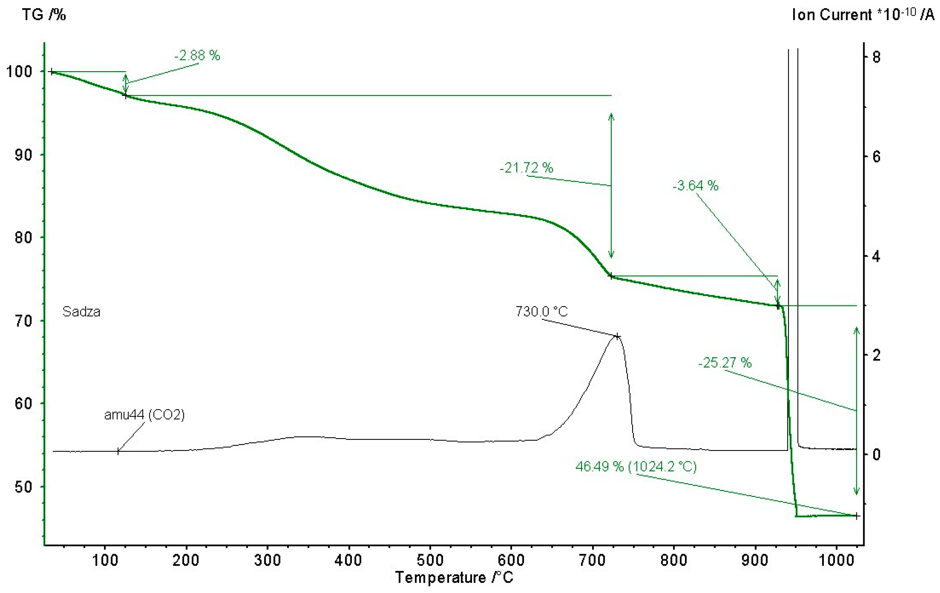
The results of the TG analysis of the soot sample are shown in Figure 10.
As can be seen from this figure, three phases of pyrolysis were observed on the TG curve:
- The first phase is connected with the evaporation of moisture present in the sample (around 2.88 wt.%), during which the CO2 concentration was equal to zero;
- After the moisture is evaporated, approx. constant ion current is observed (responsible for the molecular mass of 44, i.e., CO2), in the range of temperatures of approx. 524–914 K. During this phase, a constant decomposition of volatile matter is observed (<21.72 wt.%);
- At the temperature of 1004 K, the first peak value of the ion current was observed, which corresponds to Reaction (4), described previously, i.e., carbonates decomposition;
- At the temperature of 1214 K, the highest peak value was observed. During the following 2–3 min, the mass of the sample decreased by approx. 25 wt.%, which corresponds to the introduction of the air into the test chamber, causing sudden oxidation of the remaining carbon. Therefore, 46.49% of the total sample mass constitutes ash.
In the case of using soot in pyrometallurgical processes, it was necessary to test its explosive properties. The obtained results of the soot explosiveness tests are presented in Table 4. In order to be able to compare the obtained results, the list presents examples of explosion indicators for fine-grained anthracite dust, which is also used as a fuel in metallurgical processes [15,16,17].
Explosion data for anthracite (anthracite dust) was cited as it is also a material that is used in metallurgical processes as an alternative to coke. The presented results indicate much lower parameters determining the susceptibility to an explosion.
On the basis of the obtained results, it can be concluded that in the case of soot, due to the higher proportion of volatile flammable components, the fuel necessary for the development of the explosion itself will be available earlier than in the case of anthracite. This is confirmed by higher values of the explosion pressure and its derivative. Additionally, comparing the data contained in the table, it can be concluded that from the point of view of explosiveness, soot dust, in relation to anthracite dust, reaches higher maximum explosion pressures; moreover, the soot dust explosion is characterized by about 69% higher explosion dynamics (420 bar/s compared to 249 bar/s for the anthracite sample). The maximum value of the derivative of the explosion pressure over time, and thus the most optimal explosion conditions, was obtained for the soot sample for a much higher concentration (750 g/m3 versus 250 g/m3 for anthracite). Both fine-grained carbon-bearing materials of the sample may pose an explosion hazard, as evidenced by the value of the explosion index KSt = 1. A clear difference in the dynamics of the explosion, however, indicates that soot dust can be dangerous when used in confined spaces (e.g., in a closed metallurgical unit).
The obtained LEC parameter values indicate that the anthracite dust was not able to cause an explosion during the test, even at the highest possible concentrations, i.e., 2000 g/m3. This means that more energy is needed to initiate an explosion of anthracite dust-air mixture. This confirms the earlier conclusion that soot dust poses a greater risk from the point of view of explosiveness because an effective source of ignition with lower energy emitted to the environment will be sufficient to initiate an explosion. Minimizing the risk of explosion for a soot sample can be achieved by reducing the oxygen concentration in the air to 16%.
By analyzing the results of soot ignition tests and comparative anthracite dust (Table 5) it should be noted that it was not possible to determine the value of the MIT parameter for the anthracite sample, even with the setting of the highest possible temperature of the test device. Therefore, it should be stated that from the point of view of the minimum ignition temperature of the dust layer and cloud, the soot sample poses a greater explosion hazard than the anthracite sample. Ignition, according to the Zeldowicz mechanism [18] for a soot dust cloud, occurs as low as 674 K. This means, taking into account the safety margin defined by the standard, the surface temperature in a place where an explosive atmosphere of dust with air may arise must not exceed 541 K; likewise for the maximum surface temperature where dust can accumulate. Taking into account the safety margin at the level of 75 K, it can be concluded that this temperature should not exceed 489 K. Below these temperatures, the risk of dust-air mixture explosion as well as the risk of ignition of a dust layer <5 mm thick is negligible.
Therefore, the only possible way to use soot practically in any metallurgical aggregate is to prevent the appearance of soot dust, e.g., by agglomerating the charge.
4.3. Processing of Zinc-Bearing Waste with the Use of Soot in a Rotary Kiln
As previous studies have shown, the use of soot in the processing of zinc-bearing materials in rotary kilns is possible only if it is introduced into the aggregate only in the form of an agglomerate with other charge materials. Table 6 summarizes the obtained average chemical compositions of crude zinc oxide obtained during the processing of agglomerates with zinc-bearing materials, the characteristics of which are presented earlier in Table 2, column 1, which describes the type of zinc-bearing material present in the agglomerate.
The obtained contents of zinc and lead in crude zinc oxide indicate that the contents of these metals varied depending on the zinc-bearing materials used, from 48 to 59% by weight in the case of zinc and from 8 to 18% by weight in the case of lead. Lower zinc contents were obtained for agglomerates made with the use of charge materials that were poorer in zinc. The obtained chemical compositions of the raw zinc oxide are on the same level as those obtained in industrial conditions.
5. Conclusions
- The use of fine-grained (dusty) soot in the processing of waste zinc-bearing materials in a rotary kiln is not possible due to the risk of ignition and explosion.
- A method that allows the use of soot includes introducing them into the furnace in the form of an agglomerate with zinc-bearing charge materials.
- The content of zinc and lead in the crude oxide obtained in laboratory conditions in the process with the use of soot is at a similar level to the case of zinc oxides obtained in industrial conditions in the process with the use of coke breeze.
- Based on the test results and the analysis of the physicochemical properties of the materials used, it was found that soot, with the appropriate procedures at the stage of agglomerate preparation, meets the requirements for reducers and may be an alternative to coke breeze in the metallurgical process.
- From the point of view of fire and explosion protection, the use of the materials described in the article, as the redactors, is permissible, in particular for anthracite, whose flammability and explosive parameters are more favorable than soot and typical charges are made of carbon-bearing materials, e.g., coke. Typical ignition sources, such as surface temperature [24], will not have sufficient characteristics to ignite the dust.
Author Contributions
Conceptualization, J.Ł. and L.B.; methodology, J.Ł.; software, A.S.; validation, A.S., S.P., and M.P.; formal analysis, L.B.; investigation, S.P., M.P.; resources, A.K.; data curation, S.P.; writing—original draft preparation, L.B.; writing—review and editing, S.P.; visualization, A.K.; supervision, J.Ł.; project administration, A.S.; funding acquisition, S.P. All authors have read and agreed to the published version of the manuscript.
Funding
This research was funded by the Silesian University of Technology, grant number 11/040/BK_22/0027, “The APC was funded by 11/040/BK_22/0027”, as well as the research fund of the Main School of Fire Service.
Data Availability Statement
Not applicable.
Conflicts of Interest
The authors declare no conflict of interest.
References
- Coal Mining and Consumption in the EU. How is Poland Doing? (Language: PL). Available online: https://demagog.org.pl/analizy_i_raporty/wydobycie-i-zuzycie-wegla-w-ue-jak-wypada-polska/ (accessed on 9 May 2022).
- Łędzki, A.; Klimczyk, A.; Stachura, R.; Bernasowski, M. Rola Własności Koksu w Wybranych Piecach Szybowych. Wiad Hut 2014, 18, 765–768. [Google Scholar]
- Tochowicz, S. Wytapianie Stali w Piecach Elektrycznych, 1st ed.; Wydawnictwo Śląsk: Katowice, Poland, 1988. [Google Scholar]
- Cholewa, M.; Gawroński, J.; Przybył, M. Podstawy Procesów Metalurgicznych, 1st ed.; Wydawnictwo Politechniki Śląskiej: Gliwice, Poland, 2004. [Google Scholar]
- Lis, T. Współczesne Metody Otrzymywania Stali, 1st ed.; Wydawnictwo Politechniki Śląskiej: Gliwice, Poland, 2000. [Google Scholar]
- Łędzki, A.; Zieliński, K.; Klimczyk, A. Podstawy Technologii Wytwarzania i Przetwarzania—Część V stalownictwo; Akademia Górniczo—Hutnicza: Kraków, Poland, 2020. [Google Scholar]
- Łabaj, J. Możliwości wykorzystania odpadowych surowców węglonośnych do otrzymywania cynku i ołowiu. Rudy Met. Nieżel. 2008, 6, 350–354. [Google Scholar]
- An Introduction to Iron and Steel Processing. Available online: http://www.jfe-21st-cf.or.jp/index2.html (accessed on 8 October 2021).
- Niesler, M. (Ed.) Najlepsze Dostępne Techniki (BAT) Wytyczne dla Produkcji Stali, Stalownie Elektryczne z Odlewaniem Stali. Available online: http://www.ekoportal.gov.pl/fileadmin/Ekoportal/Pozwolenia_zintegrowane/poradniki_branzowe/5._Najlepsze_Dostepne_Techniki__BAT__wytyczne_dla_branzy_metali_zelaznych_-_stalownie_elektryczne_z_odlewaniem_stali.pdf (accessed on 23 November 2021).
- World Steel in Figures 2008, 2nd Edition. Available online: http://www.worldsteel.org/?action=publicationlist (accessed on 19 September 2021).
- Suetens, T.; Klaasen, K.; Van Acker, K.; Blanpain, B. Comparison of electric arc furnace dust treatment technologies using. J Clean Prod. 2014, 65, 152–167. [Google Scholar] [CrossRef]
- NTN Develops. “EAF Dust Briquetter” New Product and Technology Info. Available online: http://www.ntn.co.jp/english/news/news_files/new_products/2006.html (accessed on 20 October 2021).
- Czernecki, J.; Stós, E.; Botor, J.; Prajsnar, R.; Czekaj, J.; Galicki, J.; Jasiński, J. Technologia przerobu pyłów stalowniczych w piecach obrotowych. Pr. Inst. Metal Żel. 2002, 1, 17–23. [Google Scholar]
- EN IEC 60079; Explosive Atmospheres—Part 0: Equipment—General Requirements. International Electrotechnical Commission: Geneva, Switzerland, 2017.
- Eckhoff, R.K. Understanding Dust Explosions. The Role of Power Science and Technology. J. Loss Prevent. Proc. 2009, 22, 105–116. [Google Scholar] [CrossRef]
- Półka, M.; Ptak, S. Impact of Biomass Implementation on Coal Burning Installations. Proc. Eng. 2017, 192, 743–747. [Google Scholar]
- Frank, W.L. Dust explosion prevention and the critical importance of housekeeping. Proc. Saf. Prog. 2004, 23, 175–184. [Google Scholar] [CrossRef]
- Półka, M. An Analysis of Flammability and Explosion Parameters of Coke Dust and Use of Preliminary Hazard Analysis for Qualitative Risk Assessment. Sustainability 2020, 12, 4130. [Google Scholar] [CrossRef]
- ISO 13320:2020; Particle Size Analysis—Laser Diffraction Methods. International Electrotechnical Commission: Geneva, Switzerland, 2020.
- EN 14034; Part 1. Determination of Explosion Characteristics of Dust Clouds—Part 1: Determination of the Maximum Explosion Pressure pmax of Dust Clouds. International Electrotechnical Commission: Geneva, Switzerland, 2011.
- EN 14034; Part 2. Determination of Explosion Characteristics of Dust Clouds—Part 2: Determination of the Maximum Rate of Explosion Pressure Rise (dp/dt) max of Dust Clouds. International Electrotechnical Commission: Geneva, Switzerland, 2011.
- EN 14034; Part 3. Determination Of Explosion Characteristics of Dust Clouds Determination of The Lower Explosion Limit LEL Of Dust Clouds. International Electrotechnical Commission: Geneva, Switzerland, 2011.
- EN 14034; Part 4. Determination of Explosion Characteristics of Dust Clouds. Determination of the Limiting Oxygen Concentration LOC of Dust Clouds. International Electrotechnical Commission: Geneva, Switzerland, 2011.
- Perka, B.; Piwowarski, K. A Method for Determining the Impact of Ambient Temperature on an Electrical Cable during a Fire. Energies 2021, 14, 7260. [Google Scholar] [CrossRef]
Figure 1.
Scheme of the Weltz process with rotary kiln [12,13]: the colors of the drawing correspond to the zones of the furnace (yellow, orange, and red zones are 1, 2, and 3, respectively).

Figure 2.
Scheme of the rotary kiln divided into zones [12]. A detailed description of the reactions in each zone is provided below.
Figure 2.
Scheme of the rotary kiln divided into zones [12]. A detailed description of the reactions in each zone is provided below.
Figure 3.
Diagram of the granulate preparation system used in the research: 1—input material feeding system; 2—intensive mixer; 3—plate mixer; 4—granules.
Figure 3.
Diagram of the granulate preparation system used in the research: 1—input material feeding system; 2—intensive mixer; 3—plate mixer; 4—granules.
Figure 4.
Laser diffraction particle size analyzer Fritsch Analysette 22.

Figure 5.
Analyzer NETZSCH STA 449 Jupiter F1 coupled with QMS Aëolos analyzer.
Figure 6.
Twenty-liter spherical vessel manufactured by ANKO S.A.

Figure 7.
Diagram of the laboratory furnace used in the research: 1—Natural gas and air supply; 2—burner; 3—rotary kiln; 4—furnace drive; 5—rollers enabling rotary movement; 6—chute hoppers (return, burnouts); 7—process gas collector; 8—process gas cooler; 9—pulse fabric filter; 10—fan with a chimney system.
Figure 8.
View of the laboratory rotary kiln.
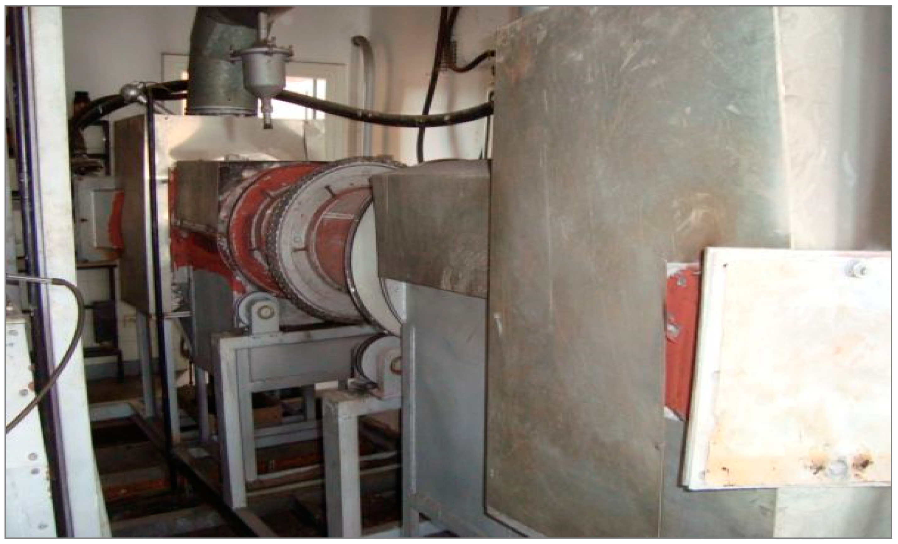
Figure 9.
Particle size distribution of soot dust sample.

Figure 10.
The results of the TG analysis of the soot dust sample.

Table 1.
The amount of coke and coke breeze consumed in pyrometallurgical processes.
| Technology | Carbon-Bearing Material Used | Consumption of Carbon-Bearing Material |
|---|---|---|
| Preparation of pig iron in a blast furnace [2] | coke | 300–500 kg/t of pig iron |
| Production of zinc in ISP technology | coke | 0.8-1.2 kg/kg Zn |
| Processing of steel dust in rotary kilns | coke breeze | 1.5–2 kg/kg Zn |
| Processing of lead secondary raw materials in rotary and shuttle furnaces | coke breeze | 50 kg/Mg Pb |
| Processing of copper slags in an electric furnace | coke | 0.25–0.4 kg/kg Cu |
Table 2.
Summary of the basic chemical composition of materials used in the research.
| Zinc-Bearing Material | Component Content, wt.% | ||||
|---|---|---|---|---|---|
| Zn | Pb | Cd | Fe | H2O | |
| Material I | 19.9 | 11.5 | 0.4 | - | 17.8 |
| Material II | 22.7 | 0.5 | 0.2 | - | 52.7 |
| Material III | 11.5 | 0.3 | 0.02 | - | 41.3 |
| Steel dust | 22.1 | 2.2 | - | 31.5 | - |
Table 3.
Selected physical and chemical properties of soot.
| Parameter | Unit | Value |
|---|---|---|
| Total carbon content | wt.% | 66–68.4 |
| Calorific value | kJ kg−1 | 22.8–33.0 |
| Sulfur content | wt.% | 0.32 |
| Volatile matter content | wt.% | 9.91 |
| Ash content | wt.% | 22.1 |
| Moisture content | wt.% | 1.7–3.5 |
Table 4.
Comparison of the explosion parameters for the tested sample and anthracite as the reference material.
Table 4.
Comparison of the explosion parameters for the tested sample and anthracite as the reference material.
| Parameter | Soot | Anthracite |
|---|---|---|
| 5.9 bar @500 g/m3 | 4.4 bar @500 g/m3 | |
| 420 bar/s @750 g/m3 | 249 bar/s @250 g/m3 | |
114 m∙bar/s @750 g/m3 | 68 m∙bar/s @250 g/m3 | |
| LEC | 125 g/m3 | n/a |
| LOC | 16% | n/a |
Table 5.
Ignition indices of tested samples.
| Parameter | Soot | Anthracite Dust |
|---|---|---|
| TCL | 674 K | >1274 K 1 |
| T5mm | 564 K | >674 K 2 |
1 no ignition according to standard requirements, single particles glowing. 2 no ignition according to standard requirements after 45 min, also for 12.5 mm thick dust layer.
Table 6.
Chemical composition of the obtained raw zinc oxide.
| Zinc-Bearing Material Used (Zn Content, wt.%) | Content, wt.% | |||
|---|---|---|---|---|
| Zn | Pb | Cd | Fe | |
| Material I (19.9) | 49.60 | 16.50 | 4.10 | - |
| Material II (22.7) | 51.43 | 17.27 | 1.66 | - |
| Material III (11.5) | 48.61 | 14.49 | 1.67 | - |
| Steel dust (22.1) | 58.87 | 8.21 | - | 0.21 |
Publisher’s Note: MDPI stays neutral with regard to jurisdictional claims in published maps and institutional affiliations. |
© 2022 by the authors. Licensee MDPI, Basel, Switzerland. This article is an open access article distributed under the terms and conditions of the Creative Commons Attribution (CC BY) license (https://creativecommons.org/licenses/by/4.0/).
Share and Cite
MDPI and ACS Style
Smalcerz, A.; Ptak, S.; Łabaj, J.; Półka, M.; Kula, A.; Blacha, L. Analysis of Using Soot Application in the Processing of Zinc-Bearing Waste Materials. Energies 2022, 15, 7969. https://doi.org/10.3390/en15217969
AMA Style
Smalcerz A, Ptak S, Łabaj J, Półka M, Kula A, Blacha L. Analysis of Using Soot Application in the Processing of Zinc-Bearing Waste Materials. Energies. 2022; 15(21):7969. https://doi.org/10.3390/en15217969
Chicago/Turabian StyleSmalcerz, Albert, Szymon Ptak, Jerzy Łabaj, Marzena Półka, Adam Kula, and Leszek Blacha. 2022. "Analysis of Using Soot Application in the Processing of Zinc-Bearing Waste Materials" Energies 15, no. 21: 7969. https://doi.org/10.3390/en15217969
Note that from the first issue of 2016, this journal uses article numbers instead of page numbers. See further details here.