
Increase the Efficiency of an Induction Motor Feed from Inverter for Low Frequencies by Combining Design and Control Improvements


Institute of Mechatronics and Information Systems, Lodz University of Technology, 90-924 Lodz, Poland
*
Author to whom correspondence should be addressed.
Energies 2022, 15(2), 530; https://doi.org/10.3390/en15020530
Submission received: 6 December 2021
/
Revised: 7 January 2022
/
Accepted: 10 January 2022
/
Published: 12 January 2022
(This article belongs to the Special Issue Design and Optimization of Fractional Kilowatt or Medium Power Electrical Machines)
Abstract
:Speed-controlled induction motors have the most significant potential for energy savings. The greatest problems with obtaining high efficiency occur in motors with a wide range of rotational speed regulation, as in the motors for driving industrial washing machines under consideration. While for the highest speeds, the dominant phenomenon is at field weakening. The problem is obtaining the optimal size of the magnetic flux for low rotation speed to prevent excessive saturation increasing current, and reduction of efficiency. This problem is usually solved by selecting the appropriate control for an already built machine. The authors propose a combination of activities when designing the motor structure with the selection of proper control, which allows for high efficiency. Since the drive does not require precise speed control or obtaining the required dynamics, it was possible to use an inexpensive control in an open loop, avoiding the cost of transmitters. Furthermore, the number of design parameters that are subject to change is significantly limited by technological factors and the available space in the washing machine. Proper parameter selection was made using a peripheral method assisted by field-circuit simulations. The proposed approach can be used in designing structures and selecting motors controls for other applications.
1. Introduction
In most countries of the world, electric motors consume up to two-thirds of the electricity generated [1]. On average, the energy consumed by an induction motor during its life cycle is 60–100 times the initial cost of the motor. The vast majority of motors are squirrel-cage induction machines. The European Union has introduced quite stringent requirements in efficiency classes (from IE1 to IE4) for motors operating at 50/60 Hz [2]. These requirements are not defined for motors operating at other frequencies, so currently produced motors operating, especially at low frequencies, have efficiency well below the requirements of the IE1 class.
Inverter-based induction motor allows for a wide adjustment of the rotational speed of the driven device without additional mechanical gears, which is one of the basic possibilities allowing to save electricity by optimally adjusting the speed to the technological process [3,4]. When fed the motor from a PWM inverter, we can choose between vector control which gives better dynamic properties and scalar control. The scalar solution is most often chosen in drives that typically operate at different frequencies, such as industrial washing machine drives, but do not require unique dynamic properties. That solution is also most often chosen because of its lower cost. The constant Volts-per-Hertz (V/f) method is the most popular of the scalar control methods. However, this method requires adjustment due to the influence of voltage drops at low supply voltage for low frequencies. The simplest solution is to enter the method of boosting the stator voltage introduced first in patent [5] and implemented in [6].
Many proposals can be found in the literature [4,6,7] for modifying the control for low frequencies with additional sensors or even without using them. However, the emphasis is in most cases on achieving the appropriate torque value with current limitations when disregarding the issue of efficiency. That is very important if the low-frequency operation is one of the rated operating states of the drive, such as in industrial washing machine drives. Optimization increasing the efficiency can be obtained through its efficiency measurement and control, ensuring optimal efficiency or at the design stage [8]. However, this solution requires the use of current and voltage converters and, as a result, a significant expansion of the drive system [9,10,11].
Since the main problem for low frequencies is selecting the appropriate flux value, a whole range of solutions has been developed to address this problem [12,13]. According to the above articles, the flux selection methods can be divided into search controllers [14] controlling the amount of flux based on the measurement of power or input current and loss-model controllers [15] that use the mathematical motor and loss model to determine the optimal flux size.
The analysis of these solutions shows that obtaining an appropriate level of efficiency is also possible using scalar V/f control. Many studies also indicate the need to account for core losses properly [16,17,18]. Although the basic losses are low at low frequencies, significant additional losses in the core can occur due to the higher harmonics generated by the motor and the supply inverter. Therefore, such motors generally have low efficiency at low frequencies.
The article considers the operation of an industrial washing machine drive, which is a typical example of a drive that requires a significant difference in rotational speeds for two basic operating states: washing and spinning. Unlike other drives, for which a continuous change of rotational speed is needed, but to a small extent and requiring a quick change of rotational speed or maintaining a constant speed under load changes, in the considered drive, there is work for significantly different frequencies, i.e., 10 or 20 Hz and 350 Hz, respectively. For this reason, the motors are generally controlled by the constant V/f control method [19,20,21,22,23] with open or closed-loop configuration. Obtaining a constant value of the electromagnetic torque with V/f control encounters difficulties in the low-frequency range due to the increasing share of voltage drops to the decreasing supply voltage. For this reason, various voltage control strategies are used, which, however, face problems related to the saturation of the magnetic circuit by the main flux and stray fluxes and the associated significant increase in the magnetizing current [22,23,24,25,26,27].
The article presents the possibilities of increasing the efficiency of an industrial washing machine drive by selecting the appropriate control characteristics, both by changing the initial voltage value (boost from 0% to 4% of rated voltage) and frequency fk (for which the voltage reaches the maximum value required for the frequency of 350 Hz), combined with a change in the design parameters specified at the machine design stage. This combination of design and control approaches is more effective than changing the control for an already made machine. It allowed obtaining high efficiency of the machine for the washing process, i.e., for frequencies of 10 and 20 Hz.
The article proposes such a design of the motor and its control strategies, which at frequencies of 10 and 20 Hz allow obtaining efficiency by over 10% higher than the currently produced motors, similar to the requirements of the IE1 class, while at the frequency of 350 Hz—meeting the requirements of the IE3 class.
The next chapter presents the research object and the effects of the changes introduced in the design and control, increasing efficiency, and the subsequent application of the auxiliary field-circuit method. A comparison of the calculation results with the measurement on the modified motor was also presented, showing the effectiveness of the applied procedure.
2. Object of Investigation
The object of the research is low-voltage, four-pole, low-power induction motors of the SK 135/60…120 series with a shaft axis height of 90 mm, designed to operate at the supply voltage frequencies of 10, 20, and 350 Hz, at which the motor is supplied with a rated voltage of 230 V (for 350 Hz). The outer diameter of the stator package is 135 mm, while the stator core lengths are 60, 80, 102, and 120 mm, respectively. These motors have 24 stator slots and 30 drop rotor slots.
Both the motors’ main dimensions were limited, resulting from the limitations imposed by washing machine manufacturers, the internal diameter of the stator, and the number of stator slots due to the technical requirements related to the use of an automatic stator coil winding. Therefore, the only design parameters that could be changed were the number of rotor slots, the dimensions of the stator and rotor slots, the number of series turns, and the diameter of the stator winding wire. For a 4-pole motor having 24 stator slots, the recommended rotor slots numbers are 18, 30, 34, and 38. Adopting too many rotor slots would require reducing the rotor tooth width, resulting in a very high tooth flux density value. On the other hand, the acceptance of 18 rotor slots was impossible due to the required value of the electromagnetic torque (especially at 350 Hz); therefore, 30 rotor slots were used. The correction of the dimensions of the stator and rotor slots was limited by the permissible values of the magnetic flux density in the stator and rotor teeth and the stator yoke. Considering the above limitations, the optimal dimensions of the stator and rotor slots were determined. The influence of the change in the number of series turns and the stator winding wire cross-section on the losses and efficiency of the motor was carried out. These changes were limited by both the stator slot filling factor and the maximum flux density values in the core and the minimum allowable values of electromagnetic torque at rated load for all motor operating frequencies. Hence, after the final selection of the number of series turns of the stator winding, the only possibility to increase the motor’s efficiency was the correction of the motor supply voltage at the frequency of 10 and 20 Hz, i.e., the selection of the appropriate inverter control.
For each of these motors, the optimal number of series turns of the stator winding and low-frequency control parameters were investigated from the motor efficiency point of view. The calculation results were obtained using the proprietary STAT_WIN program using the analytical model of the motor and the field-circuit method, using the OPERA 2D package, and verified by the measurement results. Results are generally obtained using an analytical method that allows quick conversions. As mentioned, the field-circuit method is used for a deeper look at the phenomena occurring in the motor. It was also used to correct and verify the correctness of the analytical method (of course, in parallel with the experimental research) at the stage of creating the analytical model.
For the calculations, a circuit model was used based on the equivalent diagram of an induction motor, which took into account the phenomenon of the skin effect in the rotor bars using the elementary conductors’ method and the phenomenon of core saturation with the use of the saturation coefficient determined experimentally and corrected by field calculations, common for the stator and rotor. The developed model uses the original method of calculating additional losses in the core, presented in the works [28,29,30].
The article considers the SK 135/120 motor, with the largest core length in the series, equal to 120 mm.
The required values of electromagnetic torque and rotational speed for this motor, at particular frequencies of the supply voltage, are given in Table 1.
3. Selection of the Number of Serial Coils and Control Parameters for the SK135/120 Motor with the Use of the Circuit Model
When designing the motor, the influence of the number of series turns of the stator winding was investigated. Figure 1 shows examples of motor efficiency and stator current waveforms with a core package length equal to 120 mm for a different number of series turns of the stator winding (Ns) and the load torque values given in Table 1, respectively.
The motor uses a single-layer stator winding. With 24 stator slots and serial connection of the coils, we get 4 series coils per phase. Since the coil number of turns should be an integer, for the number of series turns contained in the limits shown in Figure 1, resulting from the supply conditions, it could only be 23, 24, 25, 26, or 27; hence the number of series turns of the winding could be respectively 92, 96, 100, 104, or 108. Based on Figure 1, it can be concluded that the most favorable efficiency for this motor at low frequencies can be obtained for Ns = 96 or Ns = 100 turns, however for Ns = 100, there is an evident deterioration in efficiency at 350 Hz, so finally, the number of series turns Ns = 96 was selected.
At the same time, for this number of series turns, the current in the stator windings at the rated torque on the motor shaft does not exceed 10 A, i.e., the maximum allowable value for the supply inverter. However, when selecting the final number of series turns, one should also consider such operating characteristics of the motor as the mechanical characteristics and the current waveform in the stator winding (over the entire motor load range), especially for low frequencies, which is limited by the values allowed by the inverter supplying the motor. The values of the magnetic induction in the core and the current in the stator winding at low frequencies strongly depend on the value of the voltage supplying the motor because at this frequency in the tested motor, the operating point of the motor is most often outside of the knee of the magnetization characteristic. Therefore, choosing the proper value of the voltage supplying the motor is essential, optimal at the operating frequency of 10 Hz and 20 Hz. For this purpose, calculations were carried out for this motor for different initial values of the supply voltage and a different U/f characteristic slope; thus, a different value of the frequency fk, at which the voltage reaches the nominal value. Figure 2 shows the influence of the supply voltage on the efficiency of the SK 135/120 motor with the number of series turns Ns = 96, for the load torque values given in Table 1, and initial voltage equal to U0 = 0 (boost = 0%), and a different slope of the U/f characteristic (different values frequency fk). Since at all operating frequencies, the supply voltage control should be the same at all operating frequencies, a compromise value of the frequency fk should be selected.
Analogous waveforms for a torque of 0.01 Nm (no-load) are shown in Figure 3.
Based on Figure 4, it can be concluded that the highest efficiency under motor load for 10 Hz was obtained for the frequency fk = 74 Hz, but in this case, the current in the stator windings at the operating frequency of 20 Hz exceeds the value of 10 A. Therefore, the frequency fk value should not be less than fk = 77 Hz. At the entire range of operation at the frequency of 20 Hz and the motor load lower than the rated load, the efficiency for the frequency fk = 74 Hz was the lowest. On the other hand, increasing the frequency fk caused a shift of the efficiency maximum towards the motor load lower than the rated load, which is also unfavorable (Figure 4).
Then, in the control improvement phase, the influence of both the slope of the U/f characteristic and the initial value of the supply voltage U0 was also investigated (boost = 0, 0.5, 2, 3, and 4%) according to the relationship on the characteristics of the current, electromagnetic torque, and efficiency at the frequency of the voltage supplying the motor 10 Hz and 20 Hz. The motor power supply conditions are summarized in Table 2.
Uf = f/fk (UN − U0) + U0
Figure 5 shows the characteristics of the current, electromagnetic torque, and efficiency at the frequency of the voltage supplying the motor 10 Hz, while Figure 6 shows the relevant characteristics for the frequency of the voltage supplying the motor, equal to 20 Hz.
As can be seen from Figure 5 and Figure 6, the selection of the correct value of the initial voltage and the slope of the U/f characteristic has quite a significant influence on the characteristics of the motor at low frequencies. When selecting the power supply conditions, apart from the maximum efficiency value at the rated torque, the values of the current in the stator windings are essential, as they are limited by the permissible current for the inverter supplying the motor and should not exceed 10A in the entire operating range of the motor in investigated case. Finally, the most favorable power supply conditions were selected from the point of view of obtaining maximum efficiency with the simultaneous limitation of the current consumed by the motor, with the motor running at 10 Hz and the rated torque of 7.6 Nm and 20 Hz and the rated torque of 9.1 Nm, the variant: boost = 2% (U0 = 4.6 V) and fk = 85 Hz or boost = 4% (U0 = 9.2 V) and fk = 100 Hz, but for both of these cases, the no-load current of the motor is close to 10 A, which was not allowed according to the inverter rated data.
Therefore, the motor control variant was selected: boost = 1% (U0 = 2.3 V) and fk = 80 Hz, at which the current in the stator winding at a frequency of 10 Hz at rated load is much lower. For this case, Table 3 presents the values of the obtained efficiency of the SK135/120 motor operating at different frequencies:
For comparison, Table 3 shows the efficiency of the existing motor. As can be noted, the SK135/120 motor with the proposed control variant obtains efficiency values for the frequency of 10 and 20 Hz very similar to the requirements of the IE1 class at 50 Hz and much higher than in the motors used so far, while for the frequency of 350 Hz values two classes higher than the efficiency class of currently produced machine.
At the same time, the mechanical characteristics of the motor at both 10 Hz and 20 Hz are the most advantageous.
4. Supporting Simulation of the SK 135/120 Motor with the Use of the Field-Circuit Method
The field-circuit method allows for a deeper look at the phenomena occurring in the motor, although, of course, at the expense of greater computational complexity. The authors managed to reproduce practically all phenomena also in the analytical method previously used in the article, thanks to which a quick multivariant analysis was possible.
Figure 7 shows the BH curve and specific core loss for a wide range of frequencies, while Table 4 shows the basic dimensions used for the field-circuit model.
For field-circuit analysis, the commercial software OPERA 2D RM module with the transient eddy-current solver was chosen included rotation and a circuit description of the windings with multi-slice modeling of the skewed rotor bars [28,29,30,31,32,33,34]. Calculations of losses in the motor core using the field-circuit approach were performed using the method described in [30,35] and presented in Figure 8.
In the analytical model, the basic losses in the stator teeth were calculated for the fundamental harmonic of the field, when the tooth was divided along with the height into four layers, as the sum of the losses in each layer for the actual value of the induction occurring in this layer, while the basic losses in the stator yoke were calculated for the mean value of the induction in the yoke. In the analytical calculation of the additional core losses, the higher harmonics of the air gap’s magnetic fields were included. Total core losses were calculated as the sum of basic losses and additional surface and pulsation losses in the stator core and additional surface losses in the rotor core. A detailed description of the method can be found in the papers [30,33,34]. The results of calculating the losses in the core using the field-circuit model and obtained from the analytical formulas taking into account the higher harmonics generated in the motor while supplying the fundamental voltage harmonics were compared with the measured values showing good accuracy of the analytical method.
The tested motor at the frequency of the supply voltage of 10 Hz must achieve a shaft torque not lower than 7.6 Nm, which requires the generation of an appropriate magnetic flux value in the motor. Therefore, a 4% “boost” of the initial voltage supplying the motor is applied. Figure 9 shows the harmonics of the voltage generated by the inverter at the fundamental frequency of 10 Hz.
Time-stepping transient analysis using Opera 2d RM can be performed when the motor is powered from a sinusoidal source or when the motor is powered with the real voltage generated by the PWM inverter in the form of a square wave pulse. Testing the motor with the power supply from a sinusoidal source allows capturing the harmonics of the field and losses, which are the effect of slotting (motor design). When the motor is supplied with the actual voltage generated by the PWM inverter, we obtain harmonics originating both in the non-sinusoidal voltage shape and resulting from the slotting (as well as resulting from the superimposition of these phenomena). Therefore, for the supply with a voltage of 10 Hz, the field-circuit calculations refer to the variant of powering the motor from a sinusoidal source.
In this case, the calculations of losses were performed with the motor supplying only the basic voltage harmonic, thanks to which the losses caused by higher harmonics of the magnetic field in the motor were determined, as shown in Figure 10 and in Table 5.
Table 5 shows a comparison of the results of calculations of the losses in the motor obtained with the use of the circuit and field-circuit models with the results of measurements when the motor is powered from an inverter with a frequency of 10 Hz, while Table 6 has similar values at the frequency of 20 Hz.
Then, the results of calculations for the motor powered with a voltage of 20 Hz are presented.
All measurements were made using the measuring system shown in Figure 11. Details of the measuring system used in the article have been presented in [34].
For low-frequency power supply from the inverter, the effect of voltage distortion is visible (Figure 12). The field-circuit calculation may be performed, taking into account the actual voltage shape. For this purpose, the voltages measured at the inverter output shown in Figure 13 are saved in the form of samples (20 samples per pulse period with a frequency of 15 kHz) in a text file, which, after modification to the form of the Opera environment table, constitutes the input voltage waveform for the model. Of course, to correctly represent the phenomena, the time step with which the field-field equations are solved must be significantly reduced, on average, to the value of about 3 µs, which gives about 20 time-steps for the pulse period and about 1 time-step for the sampling period. Of course, the time step is dynamically adjusted by the algorithm using the two half-step method.
Figure 14 shows the distribution of the difference in losses from higher harmonics due to power supply from the inverter taking into account the voltage distortion.
Figure 15 and Figure 16 show the mean value of maximal induction in the stator and rotor core with the increase due to inverter supply. The voltage distortion has a significant impact on the appearance of additional induction harmonics, resulting in the creation of additional losses. As a result, some harmonics (above 25) for the stator have been reduced. This suggests that it would be possible to influence the value of losses from higher harmonics by shaping the supply voltage slightly differently. However, for low frequencies, the losses in the core are small compared to the losses in the windings, and the decisive factor for the obtained efficiency is the value of the stator and rotor currents. At the same time, as can be seen, the main influence on the increase of core losses is in the presence of stator and rotor slots. The core saturation also influences the level of losses under the influence of the main and leakage fluxes. Mainly, the leakage fluxes saturate the stator and rotor teeth’ tips, resulting in increased losses with increasing motor load and simultaneous increase in stator and rotor currents.
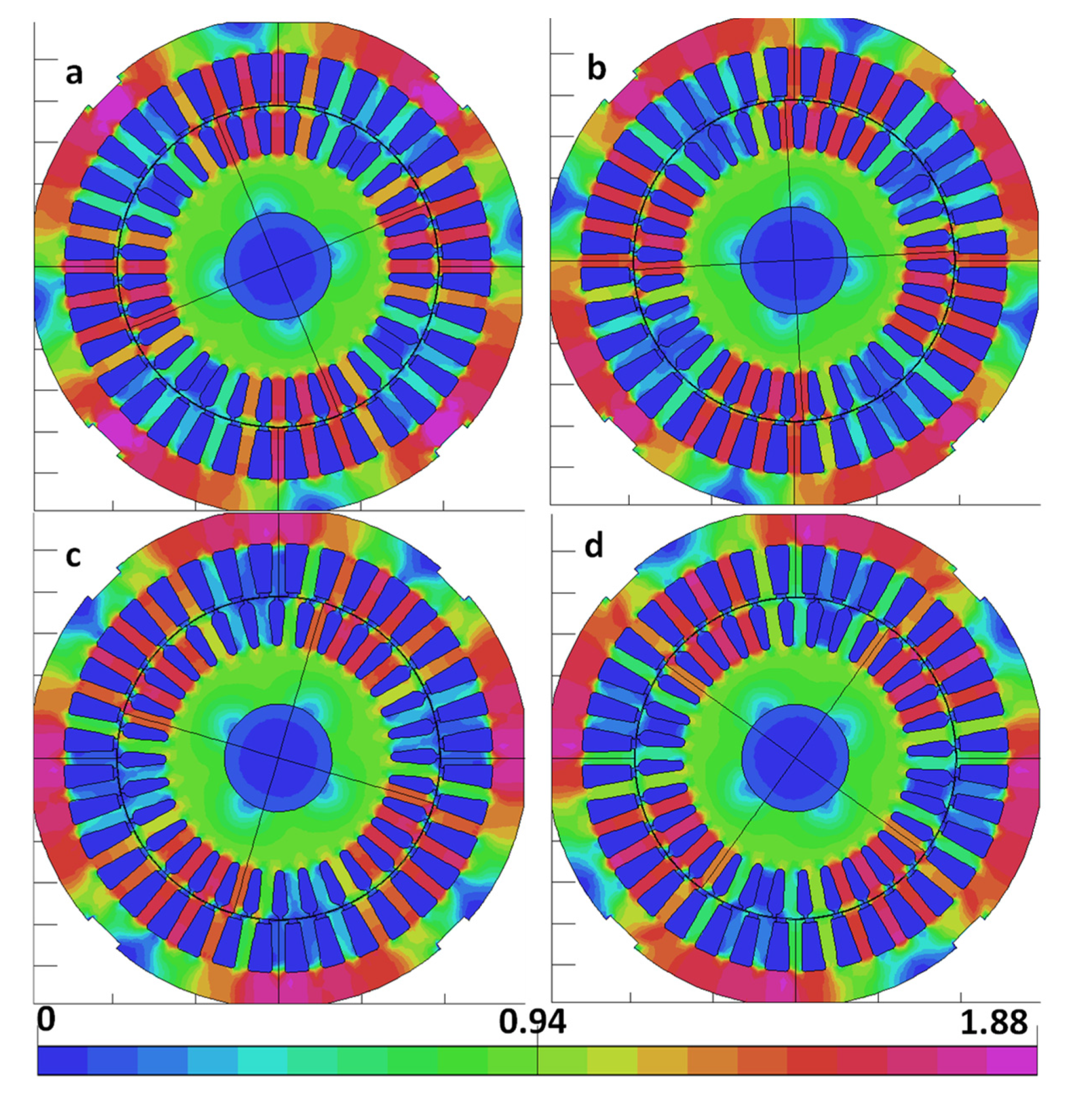
Figure 17 and Figure 18 show the distribution of the induction module in the motor for a selected time instant, respectively, for the frequencies of 10 Hz and 20 Hz (after the disappearance of transient phenomena in the motor caused by switching on the voltage, limited by the linear increase of the voltage amplitude during the first 4 voltage periods, lasting about 8 to 10 voltage periods). As can be seen, there is a significant saturation of the stator and rotor tooth heads due to the influence of the main and leakage fluxes generated by the currents flowing in the stator and rotor windings.
In the presented example, only selected elements of the control design and improvement process were considered; those that could be implemented in the tested drive. A significant limitation, in this case, was the need to obtain the required parameters both at frequencies of 10 and 20 Hz and 350 Hz. In the case of machines operating at a lower frequency range, the proposed approach simultaneously combining the process of design optimization and the drive control may give much better results.
5. Conclusions
Calculation of the losses in the core of the motor powered by an inverter requires taking into account both the higher harmonics of the magnetic field generated in the motor by the fundamental harmonic of the supply voltage and by the dominant higher harmonics produced by the inverter, the share of which is particularly significant at low frequencies of the supply voltage. For low frequencies, the share of core losses in total losses is much smaller than for higher frequencies; therefore, they have a minimal impact on the resulting motor efficiency.
The basic problem is to obtain the supply conditions for which we obtain the highest possible flux, which allows us to reduce the stator current while limiting the excessive saturation of the core by the main flux and leakage fluxes. Excessive saturation causes the magnetizing current and thus the stator current to rise rapidly.
When powered from an inverter, the permissible current supplied to the motor must be taken into account.
Good results in terms of obtaining high efficiency at low rotational speeds and frequencies are achieved by the combination of the simultaneous improvement of the design and control based on a cost-effective constant V/f method proposed in the article. Such a control method was possible because the drive does not require precise speed control or obtaining the required dynamics.
The specific conditions resulting from space limitations in the professional washing machine and technological limitations significantly reduce the number of potential decision variables. In the case of structures with less restrictive constraints and a greater number of decision variables, it would be undoubtedly beneficial to use one of the many available optimization methods. However, the combination of design optimization and control proposed in the article can be used in this case.
Author Contributions
Conceptualization, M.D. and K.K.; methodology, M.D. and K.K.; software, M.D. and J.S.; validation, J.S. and W.K.; formal analysis, M.D. and K.K.; investigation, J.S. and W.K.; resources, M.D.; data curation, M.D. and K.K.; writing—original draft preparation, M.D. and K.K.; writing—review and editing, M.D. and K.K.; supervision, M.D. and K.K.; project administration, M.D.; funding acquisition, M.D. All authors have read and agreed to the published version of the manuscript.
Funding
The work was carried out within the framework of the research project POIR.04.01.04-00-0002/16, “Developing a new optimized from the point of view of power loss design high speed three-phase induction motors used in industrial drives”, financed by NCBiR within the Operational Program Intelligent Development 2014–2020.
Informed Consent Statement
Not applicable.
Conflicts of Interest
The authors declare no conflict of interest.
References
- Ferreira, F.J.T.E.; Baoming, G.; de Almeida, A.T. Reliability and Operation of High-Efficiency Induction Motors. IEEE Trans. Ind. Appl. 2016, 52, 4628–4637. [Google Scholar] [CrossRef]
- Donolo, P.D.; Pezzani, C.M.; Bossio, G.R.; De Angelo, C.H.; Donolo, M.A. Derating of Induction Motors Due to Power Quality Issues Considering the Motor Efficiency Class. IEEE Trans. Ind. Appl. 2020, 56, 961–969. [Google Scholar] [CrossRef]
- Patil, P.V.; Naveed, S.A. Implementation of VFD Application for Speed Control of Induction Motor. In Proceedings of the 2020 International Conference on Smart Innovations in Design, Environment, Management, Planning and Computing (ICSIDEMPC), Aurangabad, India, 30–31 October 2020; pp. 168–170. [Google Scholar] [CrossRef]
- Bramerdorfer, G.; Lei, G.; Cavagnino, A.; Zhang, Y.; Sykulski, J.; Lowther, D.A. More Robust and Reliable Optimized Energy Conversion Facilitated through Electric Machines, Power Electronics and Drives, and Their Control: State-of-the-Art and Trends. IEEE Trans. Energy Convers. 2020, 35, 1997–2012. [Google Scholar] [CrossRef]
- Stich, F.A. Transistor Inverter Motor Drive Having Voltage Boost at Low Speeds. U.S. Patent No. 3,971,972, 27 July 1976. [Google Scholar]
- Shonin, O.B.; Novozhilov, N.G.; Kryltsov, S.B. Sensorless estimation of the rotor speed for the use in V/f control systems of IM drives. In Proceedings of the 2016 2nd International Conference on Industrial Engineering, Applications and Manufacturing (ICIEAM), Chelyabinsk, Russia, 19–20 May 2016; pp. 1–4. [Google Scholar] [CrossRef]
- Ito, T.; Nakamura, Y.; Mohri, K.; Uchiyama, T. Accurate Low-Speed and Torque Controls for Induction Motor with Secondary Current Feedback Using MI Sensor Installed in Shaft Hole. IEEE Trans. Magn. 2006, 42, 3515–3517. [Google Scholar] [CrossRef]
- Balasubramanian, A.; Martin, F.; Billah, M.M.; Osemwinyen, O.; Belahcen, A. Application of Surrogate Optimization Routine with Clustering Technique for Optimal Design of an Induction Motor. Energies 2021, 14, 5042. [Google Scholar] [CrossRef]
- Stopa, M.M.; Resende, M.R.; Luiz, A.A.; Justino, J.C.G.; Rodrigues, G.G.; Cardoso Filho, B.J. A Simple Torque Estimator for In-Service Efficiency Determination of Inverter-Fed Induction Motors. IEEE Trans. Ind. Appl. 2020, 56, 2087–2096. [Google Scholar] [CrossRef]
- Rengifo, J.W.; Aller, J.M. An Efficiency Estimation Method for Inverter Fed Induction Motors. In Proceedings of the 2021 IEEE Workshop on Electrical Machines Design, Control and Diagnosis (WEMDCD), Modena, Italy, 8–9 April 2021; pp. 22–27. [Google Scholar] [CrossRef]
- Stender, M.; Wallscheid, O.; Böcker, J. Accurate Torque Estimation for Induction Motors by Utilizing a Hybrid Machine Learning Approach. In Proceedings of the 2021 IEEE 19th International Power Electronics and Motion Control Conference (PEMC), Gliwice, Poland, 25–29 April 2021; pp. 390–397. [Google Scholar] [CrossRef]
- Cabezas Rebolledo, A.A.; Valenzuela, M.A. Expected Savings Using Loss-Minimizing Flux on IM Drives—Part I: Optimum Flux and Power Savings for Minimum Losses. IEEE Trans. Ind. Appl. 2015, 51, 1408–1416. [Google Scholar] [CrossRef]
- Lee, K.; Qi, J. Energy Efficiency Performance Evaluation of Direct Torque and Flux Control in Induction Machines Driven by Adjustable Speed Drives. In Proceedings of the 2020 IEEE Energy Conversion Congress and Exposition (ECCE), Detroit, MI, USA, 11–15 October 2020; pp. 2726–2731. [Google Scholar] [CrossRef]
- Kaboli, S.; Zolghadri, M.R.; Vahdati-Khajeh, E. A Fast Flux Search Controller for DTC-Based Induction Motor Drives. IEEE Trans. Ind. Electron. 2007, 54, 2407–2416. [Google Scholar] [CrossRef]
- Qu, Z.; Ranta, M.; Hinkkanen, M.; Luomi, J. Loss-Minimizing Flux Level Control of Induction Motor Drives. IEEE Trans. Ind. Appl. 2012, 48, 952–961. [Google Scholar] [CrossRef] [Green Version]
- Tan, N.A.; Lee, D. Loss Minimization Control of Sensorless Scalar-Controlled Induction Motor Drives Considering Iron Loss. In Proceedings of the 2018 International Power Electronics Conference (IPEC-Niigata 2018-ECCE Asia), Niigata, Japan, 20–24 May 2018; pp. 478–482. [Google Scholar] [CrossRef]
- Von Pfingsten, G.; Steentjes, S.; Hameyer, K. Operating Point Resolved Loss Calculation Approach in Saturated Induction Machines. IEEE Trans. Ind. Electron. 2017, 64, 2538–2546. [Google Scholar] [CrossRef]
- Wang, K.; Huai, R.; Yu, Z.; Zhang, X.; Li, F.; Zhang, L. Comparison Study of Induction Motor Models Considering Iron Loss for Electric Drives. Energies 2019, 12, 503. [Google Scholar] [CrossRef] [Green Version]
- Chen, W.; Xu, D.; Yang, R.; Yu, Y.; Xu, Z. A novel stator voltage oriented V/F control method capable of high output torque at low speed. In Proceedings of the 2009 International Conference on Power Electronics and Drive Systems (PEDS), Taipei, Taiwan, 2–5 November 2009; pp. 228–233. [Google Scholar] [CrossRef]
- Mohammed Youssef, O.E. A New Open-Loop Volts/Hertz Control Method for Induction Motors. In Proceedings of the 2018 Twentieth International Middle East Power Systems Conference (MEPCON), Cairo, Egypt, 18–20 December 2018; pp. 266–270. [Google Scholar] [CrossRef]
- Wu, D.; Chang, C.; Fang, Y.; Bai, H. Performance improvement of V/f induction-motor control in the low-frequency range. In Proceedings of the 8th International Conference on Advances in Power System Control, Operation and Management (APSCOM 2009), Hong Kong, China, 8–11 November 2009; pp. 1–6. [Google Scholar] [CrossRef]
- Pongpant, J.; Po-ngam, S.; Konghirun, M. The Performance Improvement of Constant V/f Control of Induction Motor Drive in Low Speed Range. In Proceedings of the TENCON 2006—2006 IEEE Region 10 Conference, Hong Kong, China, 14–17 November 2006; pp. 1–4. [Google Scholar] [CrossRef]
- Smith, A.; Gadoue, S.; Armstrong, M.; Finch, J. Improved method for the scalar control of induction motor drives. Electr. Power Appl. IET 2013, 7, 487–498. [Google Scholar] [CrossRef] [Green Version]
- Jo, G.-J.; Choi, J.-W. Rotor Field-Oriented V/f Drive System Implementation with Oscillation Suppression Compensator in Induction Motors. IEEE J. Emerg. Sel. Top. Power Electron. 2021, 9, 2745–2758. [Google Scholar] [CrossRef]
- Boldea, I.; Moldovan, A.; Tutelea, L. Scalar V/f and I-f control of AC motor drives: An overview. In Proceedings of the 2015 Intl Aegean Conference on Electrical Machines & Power Electronics (ACEMP), 2015 Intl Conference on Optimization of Electrical & Electronic Equipment (OPTIM) & 2015 Intl Symposium on Advanced Electromechanical Motion Systems (ELECTROMOTION), Side, Turkey, 2–4 September 2015; pp. 8–17. [Google Scholar] [CrossRef]
- Yussif, N.; Sabry, O.H.; Abdel-Khalik, A.S.; Ahmed, S.; Mohamed, A.M. Enhanced Quadratic V/f-Based Induction Motor Control of Solar Water Pumping System. Energies 2021, 14, 104. [Google Scholar] [CrossRef]
- Pimkumwong, N.; Wang, M.-S. Online Speed Estimation Using Artificial Neural Network for Speed Sensorless Direct Torque Control of Induction Motor based on Constant V/F Control Technique. Energies 2018, 11, 2176. [Google Scholar] [CrossRef] [Green Version]
- Dems, M.; Komeza, K. The Influence of Electrical Sheet on the Core Losses at No-Load and Full-Load of Small Power Induction Motors. IEEE Trans. Ind. Electron. 2017, 64, 2433–2442. [Google Scholar] [CrossRef]
- Dems, M.; Komeza, K. Performance Characteristics of a High-Speed Energy-Saving Induction Motor with an Amorphous Stator Core. IEEE Trans. Ind. Electron. 2014, 61, 3046–3055. [Google Scholar] [CrossRef]
- Dems, M.; Komeza, K. Finite element and analytical calculations of no-load core losses in energy-saving induction motors. IEEE Trans. Ind. Electron. 2012, 59, 2934–2946. [Google Scholar] [CrossRef]
- Dems, M.; Komeza, K.; Majer, K. Core losses of the induction motor operating in a wide frequency range supplied from the inverter. Int. J. Appl. Electromagn. Mech. 2020, 64, S65–S82. [Google Scholar] [CrossRef]
- Dems, M.; Komeza, K.; Rodríguez, H.G. Methods for increasing the efficiency of an asynchronous motor with increased speed fed from the PWM inverter. Int. J. Appl. Electromagn. Mech. 2018, 57, 61–71. [Google Scholar] [CrossRef]
- Dems, M.; Komeza, K.; Wiak, S.; Stec, T.; Kikosicki, M. Application of circuit and field-circuit methods in designing process of small induction motors with stator cores made from amorphous iron. Int. J. Comput. Math. Electr. Electron. Eng. 2006, 25, 283–296. [Google Scholar] [CrossRef]
- Dems, M.; Komeza, K. Designing an energy-saving induction motor operating in a wide frequency range. IEEE Trans. Ind. Electron. 2022, 69, 4387–4397. [Google Scholar] [CrossRef]
- Dems, M.; Komeza, K.; Wiak, S.; Stec, T. The highly efficient three-phase small induction motors with stator cores made from amorphous iron. COMPEL—Int. J. Comput. Math. Electr. Electron. Eng. 2004, 23, 625–632. [Google Scholar] [CrossRef]
Figure 1.
Efficiency (a) and stator current (b) of the SK135/120 motor as a function of the number of series turns of the stator winding for different frequencies of the supply voltage (boost 2%, fk = 85 Hz).
Figure 1.
Efficiency (a) and stator current (b) of the SK135/120 motor as a function of the number of series turns of the stator winding for different frequencies of the supply voltage (boost 2%, fk = 85 Hz).
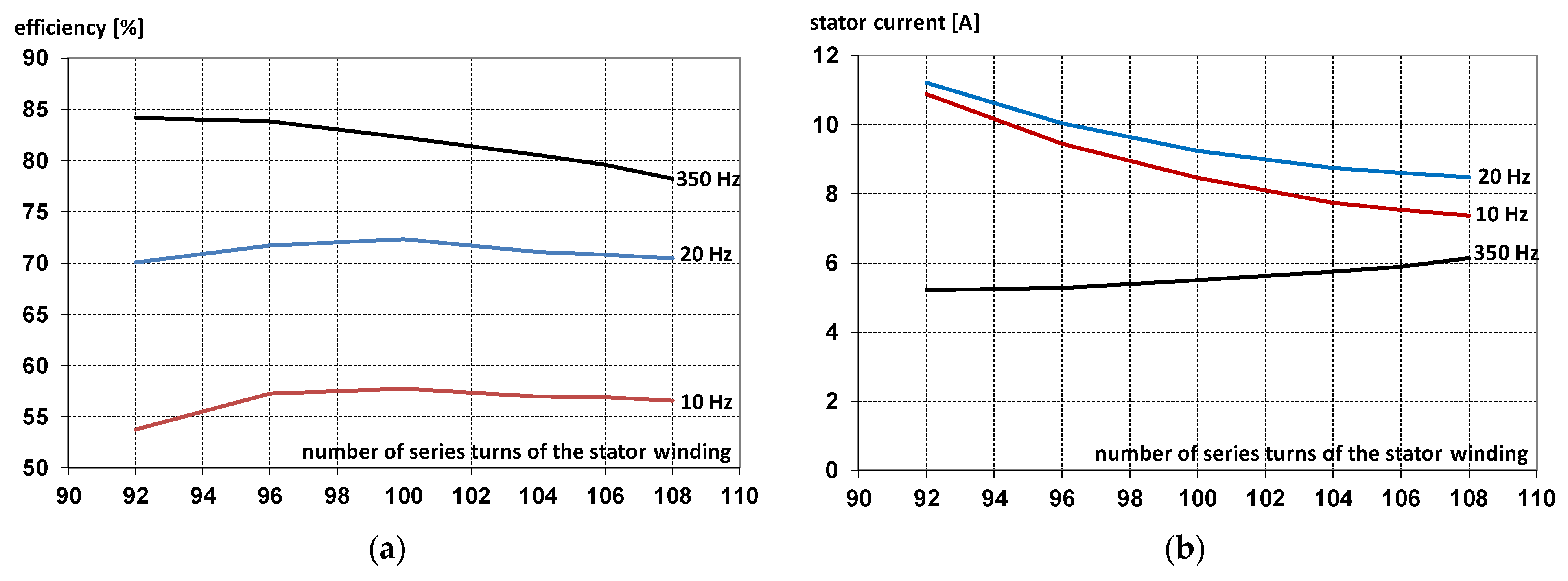
Figure 2.
Efficiency (a) and stator current (b) of the SK135/120 motor for different slopes of the U/f characteristic at the frequency of the supply voltage 10 Hz, torque = 7.6 Nm, and 20 Hz, torque = 9.1 Nm; U0 = 0, number of series turns Ns = 96.
Figure 2.
Efficiency (a) and stator current (b) of the SK135/120 motor for different slopes of the U/f characteristic at the frequency of the supply voltage 10 Hz, torque = 7.6 Nm, and 20 Hz, torque = 9.1 Nm; U0 = 0, number of series turns Ns = 96.

Figure 3.
Efficiency (a) and stator current of (b) the SK135/120 motor for different slopes of the U/f characteristic at the frequency of the supply voltage 10 Hz and 20 Hz; U0 = 0, number of series turns Ns = 96, torque = 0.01 Nm.
Figure 3.
Efficiency (a) and stator current of (b) the SK135/120 motor for different slopes of the U/f characteristic at the frequency of the supply voltage 10 Hz and 20 Hz; U0 = 0, number of series turns Ns = 96, torque = 0.01 Nm.
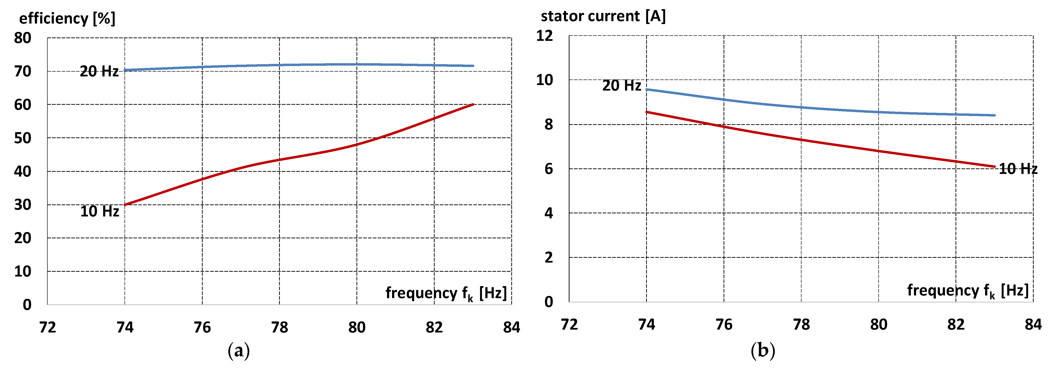
Figure 4.
Efficiency curve as a function of the motor load torque SK135/120 for different U/f slope at the frequency of the supply voltage 10 Hz (left) and 20 Hz (right), U0 = 0, number of series turns Ns = 96.
Figure 4.
Efficiency curve as a function of the motor load torque SK135/120 for different U/f slope at the frequency of the supply voltage 10 Hz (left) and 20 Hz (right), U0 = 0, number of series turns Ns = 96.

Figure 5.
Torque vs. slip (a), current (b) and efficiency (c) curve as a function of the motor load torque SK135/120 for different U/f slope and different values of U0 at the frequency of the supply voltage 10 Hz, number of series turns Ns = 96.
Figure 5.
Torque vs. slip (a), current (b) and efficiency (c) curve as a function of the motor load torque SK135/120 for different U/f slope and different values of U0 at the frequency of the supply voltage 10 Hz, number of series turns Ns = 96.
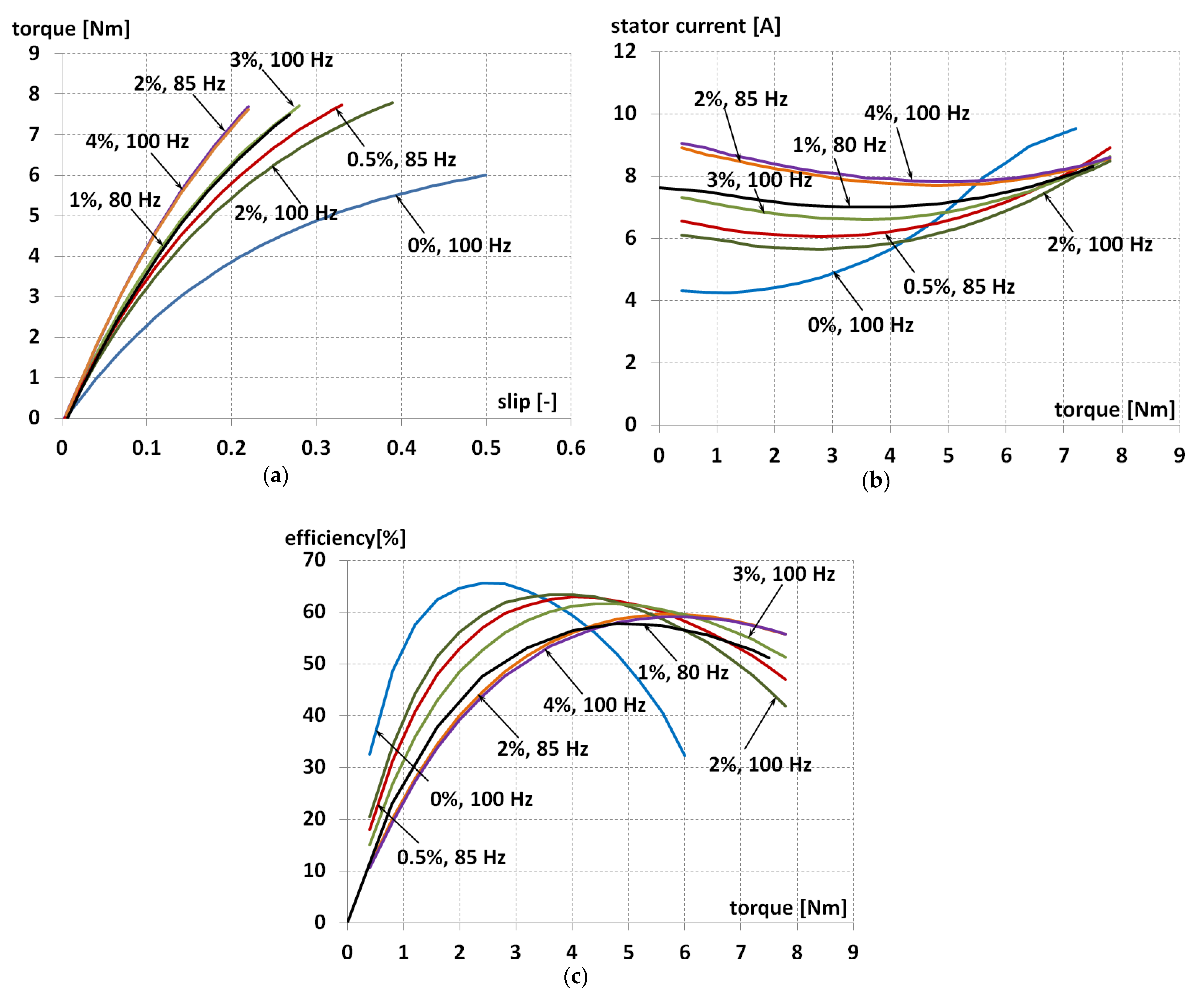
Figure 6.
Torque (a), current (b), and efficiency (c) curve as a function of the motor load torque SK135/120 for different U/f slope and different values of U0 at the frequency of the supply voltage 20 Hz, number of series turns Ns = 96.
Figure 6.
Torque (a), current (b), and efficiency (c) curve as a function of the motor load torque SK135/120 for different U/f slope and different values of U0 at the frequency of the supply voltage 20 Hz, number of series turns Ns = 96.

Figure 7.
Magnetization characteristics (a) and specific core loss for stator and rotor core material M270-35A (thickness 0.35 mm) (b).
Figure 7.
Magnetization characteristics (a) and specific core loss for stator and rotor core material M270-35A (thickness 0.35 mm) (b).
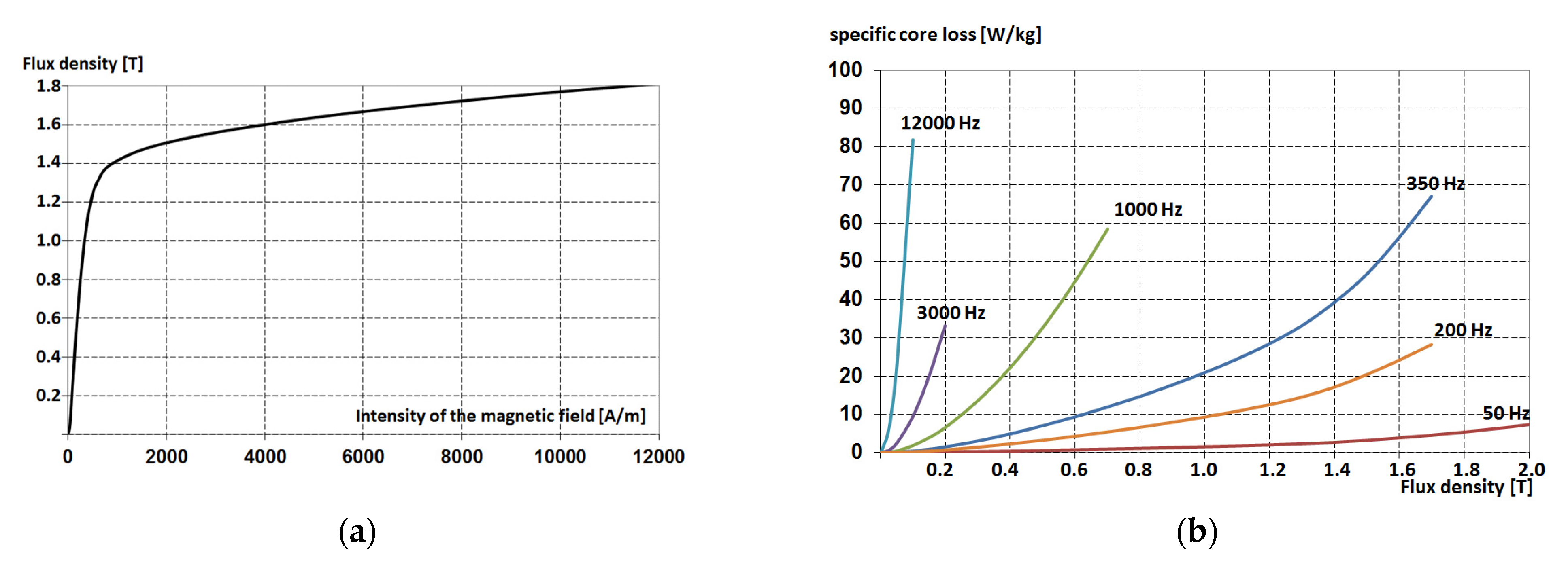
Figure 8.
Flowchart of the motor losses calculation with the use of the field-circuit method.

Figure 9.
The harmonic content of the supply voltage at the output frequency of 10 Hz.

Figure 10.
Stator and rotor core losses for higher harmonics when supplying the motor with the 1st harmonic of the voltage with a frequency of 10 Hz.
Figure 10.
Stator and rotor core losses for higher harmonics when supplying the motor with the 1st harmonic of the voltage with a frequency of 10 Hz.
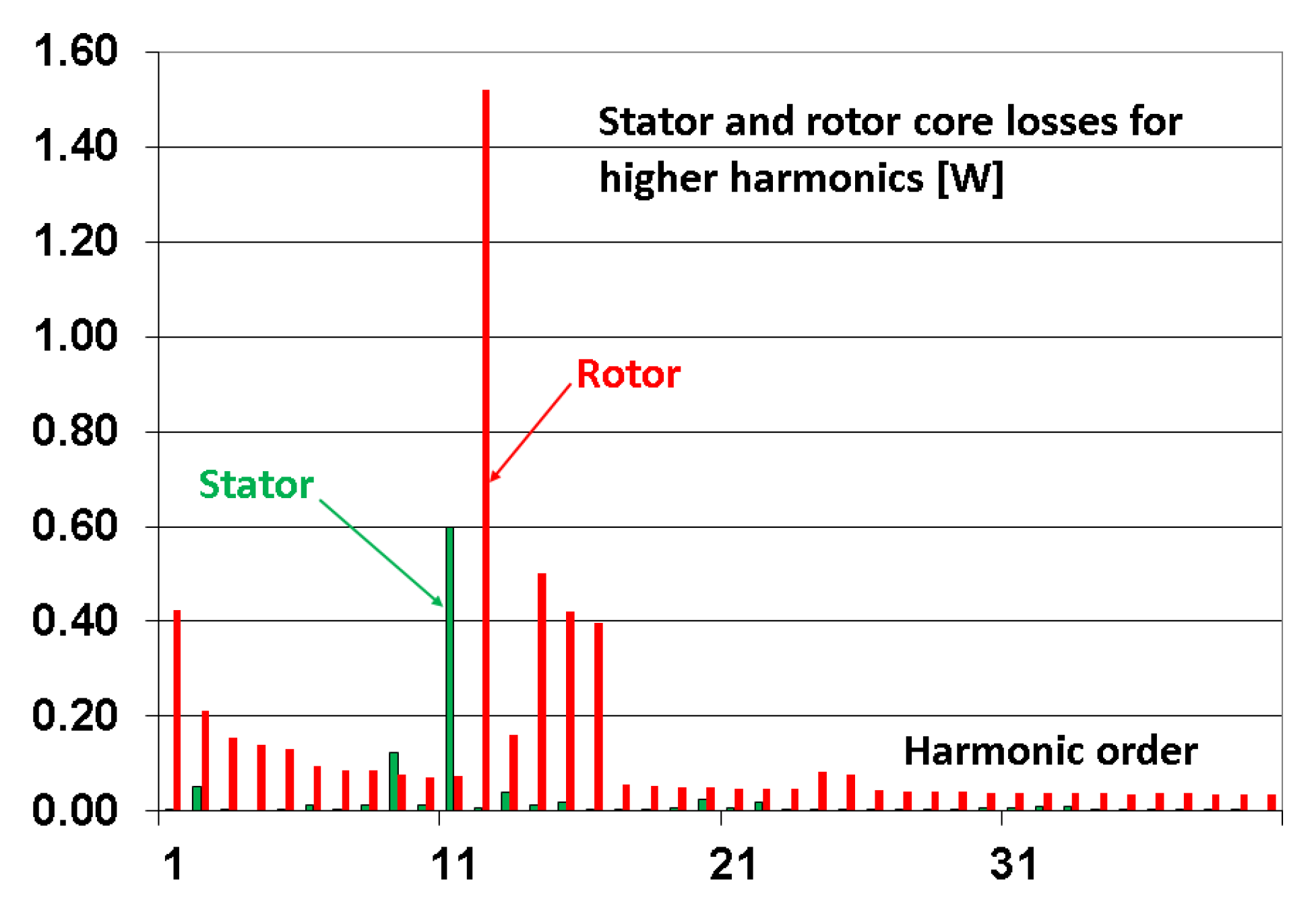
Figure 11.
The harmonic content of the supply voltage at the output frequency of 20 Hz.

Figure 12.
The measuring system: 1, test motor; 2, hysteresis brake provides precise torque loading independent of shaft speed with the accuracy: ±0.25% (full scale); 3, supply system (the mains or PWM inverter); 4, precise current transducers; 5, a multi-channel analog-to-digital converter; 6, voltage transducers; 7, thermocouples built-in during the model’s construction, with the signal from sensors in the rotor being transmitted wirelessly to the external system; 8 and 9, torque and speed transducers; 10, the measuring system running under the control of the LabView program.
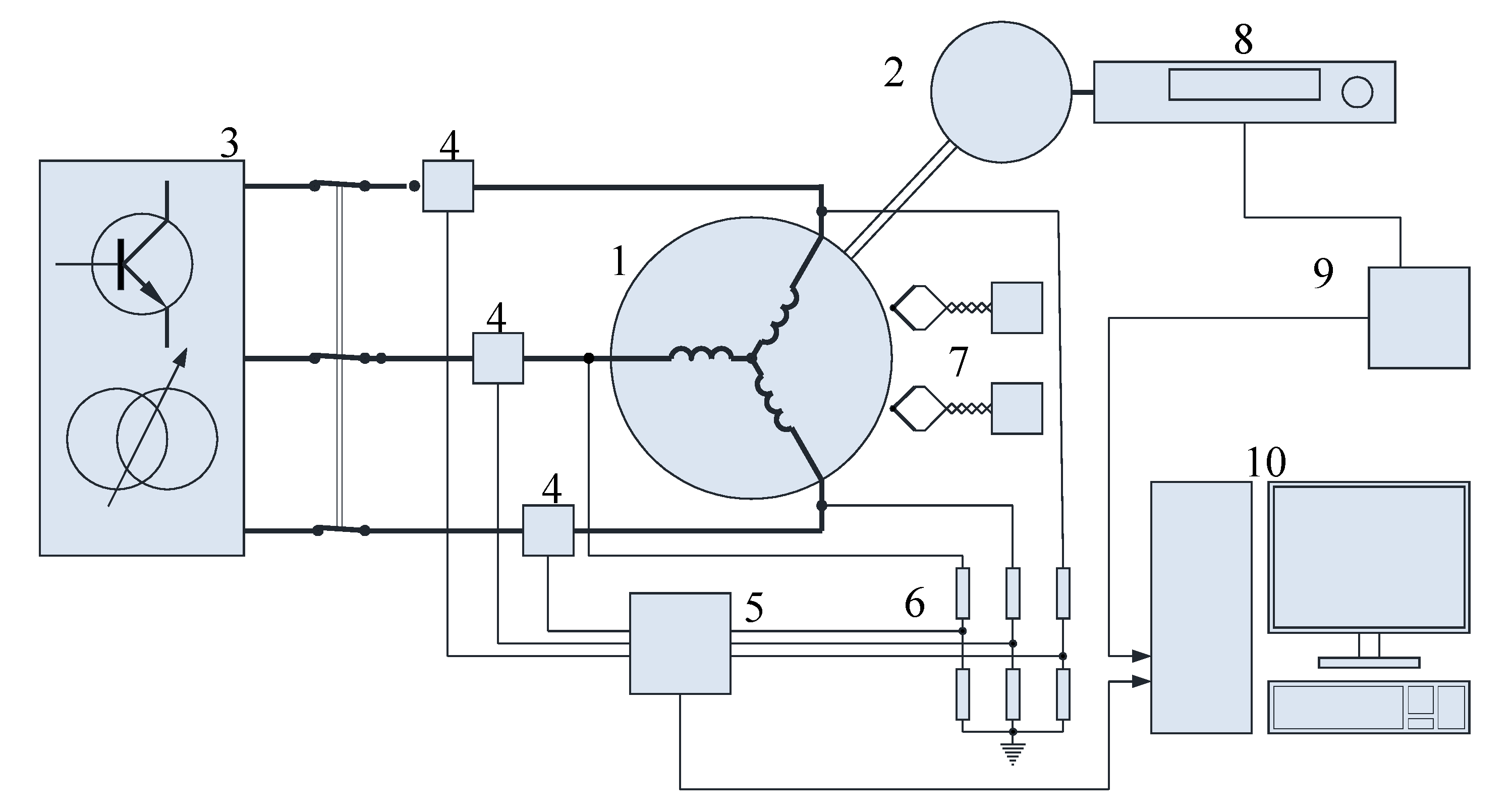
Figure 13.
Measured phase voltage (a) and currents (b) versus time.
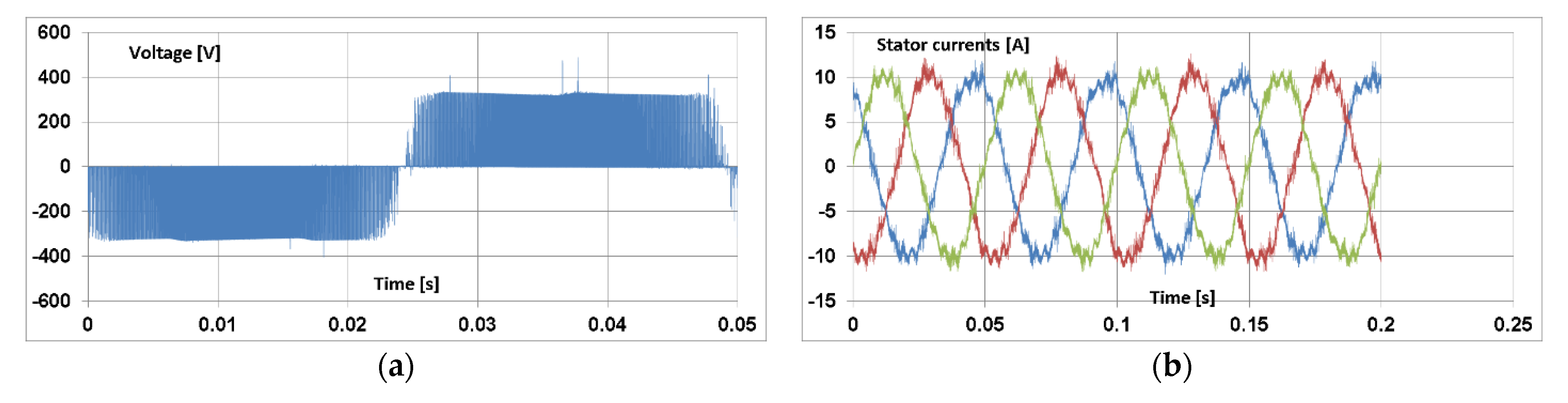
Figure 14.
The difference in stator (a) and rotor (b) core losses for higher harmonics when supplying the motor with the inverter voltage frequency of 20 Hz.
Figure 14.
The difference in stator (a) and rotor (b) core losses for higher harmonics when supplying the motor with the inverter voltage frequency of 20 Hz.
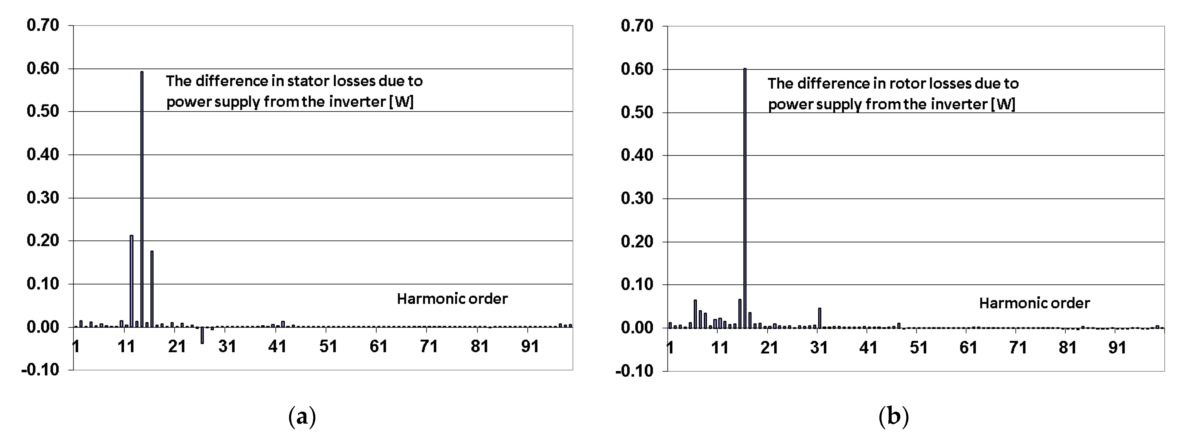
Figure 15.
Mean value of maximal induction in the stator core (a) with the increase (b) due to inverter supply.
Figure 15.
Mean value of maximal induction in the stator core (a) with the increase (b) due to inverter supply.
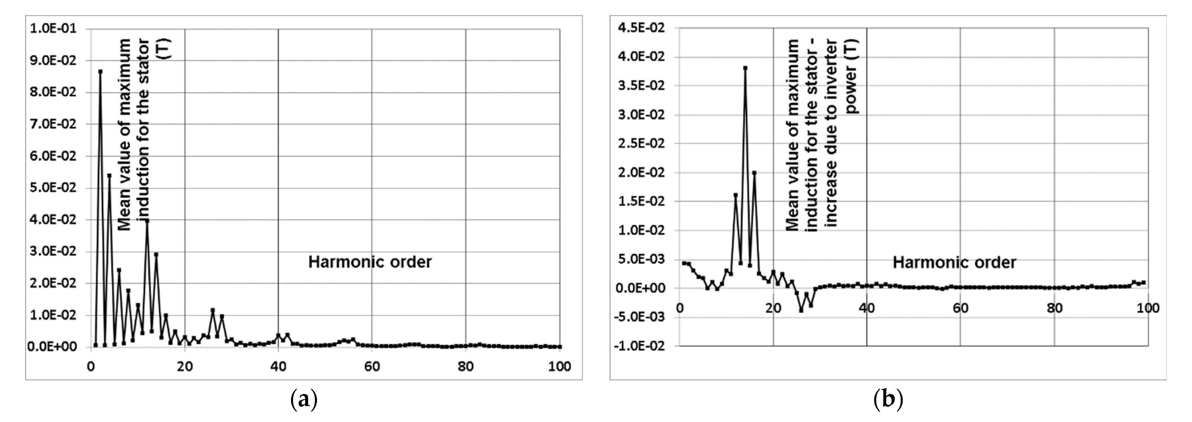
Figure 16.
Mean value of maximal induction (a) in the rotor core with the increase (b) due to inverter supply.
Figure 16.
Mean value of maximal induction (a) in the rotor core with the increase (b) due to inverter supply.
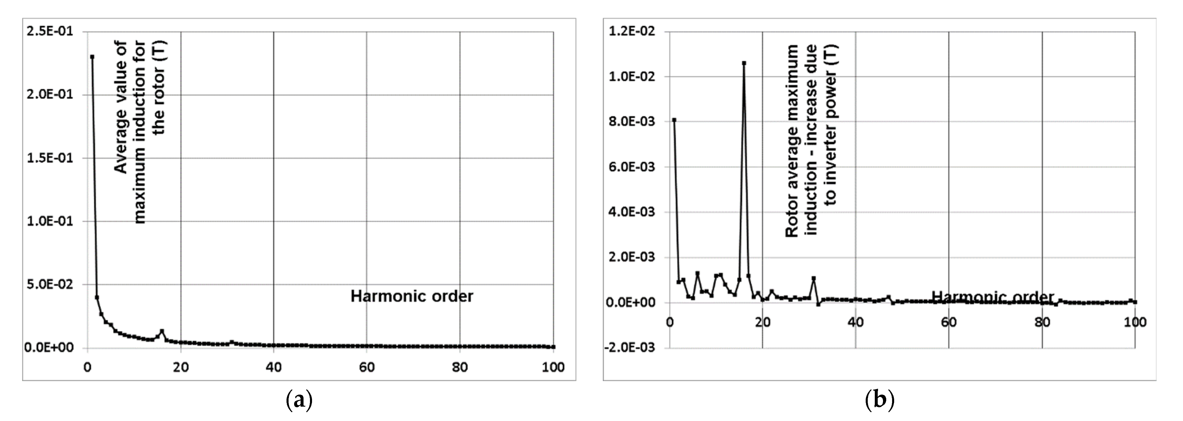
Figure 17.
Distribution of the magnetic induction module for the motor load with the rated torque when supplied with a voltage of 10 Hz (for time (a), 5 s; (b), 5.00625 s; (c), 5.0125 s; (d), 5.01875 s).
Figure 17.
Distribution of the magnetic induction module for the motor load with the rated torque when supplied with a voltage of 10 Hz (for time (a), 5 s; (b), 5.00625 s; (c), 5.0125 s; (d), 5.01875 s).

Figure 18.
Distribution of the magnetic induction module for the motor load with the rated torque when supplied with a voltage of 20 Hz from PWM inverter (for time (a), 2 s; (b), 2.00625 s; (c), 2.0125 s; (d), 2.01875 s).
Figure 18.
Distribution of the magnetic induction module for the motor load with the rated torque when supplied with a voltage of 20 Hz from PWM inverter (for time (a), 2 s; (b), 2.00625 s; (c), 2.0125 s; (d), 2.01875 s).

Table 1.
Required torque value and rotor speed of the SK 135/120 motor.
| f Hz | Torque Nm | Rotor Speed rpm |
|---|---|---|
| 10 | 7.6 | 211 |
| 20 | 9.1 | 487 |
| 350 | 1.3 | 10,087 |
Table 2.
Motor supply conditions at different values of the initial voltage and different slopes of the U/f characteristic curve when the motor is supplied with 10 Hz and 20 Hz.
Table 2.
Motor supply conditions at different values of the initial voltage and different slopes of the U/f characteristic curve when the motor is supplied with 10 Hz and 20 Hz.
| Boost | fk | U0 | U (for 10 Hz) | U (for 20 Hz) |
|---|---|---|---|---|
| % | Hz | V | V | V |
| 0 | 100 | 0 | 23.0 | 46.0 |
| 0.5 | 85 | 1.15 | 28.1 | 55.0 |
| 1.0 | 80 | 2.3 | 30.8 | 59.2 |
| 2.0 | 85 | 4.6 | 31.1 | 57.6 |
| 2.0 | 100 | 4.6 | 27.1 | 49.7 |
| 3.0 | 100 | 6.9 | 29.2 | 51.5 |
| 4.0 | 100 | 9.2 | 31.3 | 53.4 |
Table 3.
SK 135/120 motor efficiency at 10 Hz, 20 Hz and 350 Hz; boost = 1%, fk = 80 Hz.
| Output | Efficiency | Efficiency Class for 50 Hz | |||||
|---|---|---|---|---|---|---|---|
| f Hz | Torque Nm | Power [W] | SK135/120 % | Existing Motor % | IE1 % | IE2 | IE3 |
| 10 | 7.6 | 170 | 54.7 | 42.1 | 56.5 | 64.5 | 69.5 |
| 20 | 9.1 | 500 | 69.0 | 61.5 | 69.0 | 76.0 | 80.0 |
| 350 | 1.3 | 1400 | 85.7 | 76.9 | 76.7 | 82.5 | 85.5 |
Table 4.
Basic dimensions of the motor for the field-circuit model.
| Data | Symbol | Unit | SK135/120 |
|---|---|---|---|
| Stator outer diameter | Dse | mm | 135 |
| Stator inner diameter | Dsi | mm | 77 |
| Rotor inner diameter | Dri | mm | 26 |
| Core length | Ls | mm | 120 |
| Air gap thickness | δ | mm | 0.3 |
Table 5.
The results of the loss calculations for the motor load condition with the supply from PWM with frequency 10 Hz (mechanical losses Pm = 0.65 W, M = 7.796 Nm, boost = 1%, fk = 80 Hz).
Table 5.
The results of the loss calculations for the motor load condition with the supply from PWM with frequency 10 Hz (mechanical losses Pm = 0.65 W, M = 7.796 Nm, boost = 1%, fk = 80 Hz).
| Model | Stator Winding | Rotor Winding | Motor Core |
|---|---|---|---|
| (W) | (W) | (W) | |
| circuit | 86.5 | 64.6 | 11.7 |
| field-circuit | 89.95 | 78.10 | 12.05 |
| measurements | 90.8 | 70.6 | 14.9 |
Table 6.
The results of the loss calculations for the motor load condition with the supply from PWM with frequency 20 Hz (mechanical losses Pm = 1.66 W, M = 7.796 Nm, boost = 1%, fk = 80 Hz).
Table 6.
The results of the loss calculations for the motor load condition with the supply from PWM with frequency 20 Hz (mechanical losses Pm = 1.66 W, M = 7.796 Nm, boost = 1%, fk = 80 Hz).
| Model | Stator Winding | Rotor Winding | Motor Core |
|---|---|---|---|
| (W) | (W) | (W) | |
| circuit | 91.6 | 52.0 | 31.9 |
| field-circuit | 81.7 | 69.82 | 38.75 |
| measurements | 94.6 | 57.2 | 33.2 |
Publisher’s Note: MDPI stays neutral with regard to jurisdictional claims in published maps and institutional affiliations. |
© 2022 by the authors. Licensee MDPI, Basel, Switzerland. This article is an open access article distributed under the terms and conditions of the Creative Commons Attribution (CC BY) license (https://creativecommons.org/licenses/by/4.0/).
Share and Cite
MDPI and ACS Style
Dems, M.; Komeza, K.; Szulakowski, J.; Kubiak, W. Increase the Efficiency of an Induction Motor Feed from Inverter for Low Frequencies by Combining Design and Control Improvements. Energies 2022, 15, 530. https://doi.org/10.3390/en15020530
AMA Style
Dems M, Komeza K, Szulakowski J, Kubiak W. Increase the Efficiency of an Induction Motor Feed from Inverter for Low Frequencies by Combining Design and Control Improvements. Energies. 2022; 15(2):530. https://doi.org/10.3390/en15020530
Chicago/Turabian StyleDems, Maria, Krzysztof Komeza, Jacek Szulakowski, and Witold Kubiak. 2022. "Increase the Efficiency of an Induction Motor Feed from Inverter for Low Frequencies by Combining Design and Control Improvements" Energies 15, no. 2: 530. https://doi.org/10.3390/en15020530
Note that from the first issue of 2016, this journal uses article numbers instead of page numbers. See further details here.