
Effect of Overhead Contact Line Pre-Sag on the Interaction Performance with a Pantograph in Electrified Railways

1
State Key Laboratory of Traction Power, Southwest Jiaotong University, Chengdu 610031, China
2
Department of Structural Engineering, Norwegian University of Science and Technology, 7491 Trondheim, Norway
*
Author to whom correspondence should be addressed.
Energies 2022, 15(19), 6875; https://doi.org/10.3390/en15196875
Submission received: 1 August 2022
/
Revised: 14 September 2022
/
Accepted: 15 September 2022
/
Published: 20 September 2022
(This article belongs to the Special Issue Vehicles Dynamics and Propulsion Technologies)
Abstract
:In the high-speed rail industry, the overhead contact line erected along the railroad is used to supply the electricity to the high-speed train via a pantograph on the carbody’s roof. This work attempts to explore the effect of contact line pre-sag on the contact quality between the pantograph and the contact line. A nonlinear finite element approach is implemented to build the overhead contact line system with accurate description of the pre-sag of the contact line. Through a nonlinear solution, the effect of contact line pre-sag on the contact force is analysed with different train speeds and tension classes. The analysis result indicates the feasibility of tuning the pre-sag to improve the interaction performance at a given speed and tension class. In the low-speed range, the change of pre-sag does not have a significant effect on the interaction performance. However, when the speed increases up to a certain value, the effect of pre-sag on the contact force is nonnegligible. The increase in tension can reduce the sensitivity of the interaction performance to the pre-sag. An optimisation procedure is implemented to obtain the optimal amount of pre-sag for different train speeds and tension classes. The results indicate a necessity to include a certain amount of contact line pre-sag to maintain an excellent interaction performance at high speed.
1. Introduction
The overhead contact line is a special equipment erected along the high-speed railroad to transmit the electricity to the locomotive via a pantograph on the carbody’s roof, as illustrated in Figure 1. The high-speed pantograph slides through the contact line to provide a continuous electrical current for the engine in the electric train. The contact quality of the pantograph and the overhead contact line are the key factors affecting the current collection quality of the high-speed train. Satisfactory contact quality is desired to ensure a safe and stable high-speed rail operation without traffic disorders and accidents.
1.1. Problem Description
The overhead contact line consists of several tensioned cables, namely, the messenger line, contact line and droppers. The contact line serves as the sliding path of the pantograph head, of which the geometry is quite important to the interaction performance of the pantograph and overhead contact line. According to the industrial experience [1], a certain amount of pre-sag reserved for the contact line is beneficial for the pantograph’s passing, as shown in Figure 2. For instance, in China’s high-speed network, a pre-sag of 0.5‰ is set for Beijing-Tianjin high-speed railway contact line. Therefore, fundamental research is necessary to find out how the pre-sag affects the interaction performance with various types of overhead contact line and different operating speeds.
1.2. Literature Review
As the overhead contact line system suffers multiple impacts from the pantograph [2], wind load [3,4,5,6], vehicle-track perturbations [7,8,9,10,11], electric shocks [12], temperature variance [13,14,15] and some other types of disturbances [16,17], almost all the rail operators have widely recognised the overhead contact line as the most vulnerable part in the traction power system [18]. Therefore, the dynamics of the overhead contact line and the pantograph have attracted ever-increasing attention from many scholars. In order to maintain good service performance, various monitoring techniques have been developed to master the health condition of the overhead contact line [18,19]. In [20], a high-precision detection approach was developed for measuring the geometry parameters. In [21], the cantilever devices of the overhead contact line were monitored using 3D point cloud data. In [22,23,24,25], convolutional neural networks were utilised to detect various types of errors in the overhead contact line system. Based on an improved multivariate statistical control chart, a comprehensive evaluation method for the status of the overhead contact line was proposed in [26]. As field tests have a tremendous economic cost, mathematical models have been the primary tool to explore the interaction performance of the pantograph and the overhead contact line [27]. A lumped-parameter model was usually used to simulate the linear dynamic behaviours of the overhead contact line in the early era [28]. This simple model can only be used to describe the stiffness variance distribution along the contact line and does not have the capability to describe more complex continuous characteristics, such as the wave propagation and the pre-sag of the contact line [29,30,31]. With an increase in the train speed, wave propagation has been demonstrated to play an ever-increasing role in affecting dynamic performance [10]. Some continuous models were developed based on various numerical modelling approaches [32,33,34,35]. Among various numerical models, the finite element method (FEM) is the most popular one due to its efficiency in tackling the nonlinearities in modelling the overhead contact line [36,37]. The numerical results evaluated by existing models were compared and summarised in [27] to build a simulation benchmark to validate numerical results. The pantograph mounted on the train roof was usually modelled by a two or three-stage lumped mass model [38,39,40], which describes two or three essential modes [41]. This assumption is generally accepted as this simple model and can efficiently simulate the response at 0–20 Hz, which is the main range of the frequency of interest specified in the assessment standard En 50367 [42]. Recently, in order to represent the physical configuration of a real pantograph, the improved multibody pantograph model has been built by some scholars [33,43,44]. These models can be used to optimise pantograph geometry [45], and develop the active controller [46] and passive dampers [47]. The external perturbations and the errors in the overhead contact line are properly modelled to investigate their effects on contact quality. The stochastic wind field for the overhead contact line was generated in [48,49,50], and the buffeting of the contact line was analysed. The aerodynamic instability of the contact line subjected to wind load has been demonstrated to have the potential to trigger a large amplitude vibration called galloping [51,52]. Once it happens, the train service has to stop, as it is impossible for the pantograph to the contact line to collect the current [53]. The carbody’s vibration caused by the track irregularities was introduced in the pantograph model to evaluate the current collection quality [54]. The ice-coating effect of the contact line on the contact force was investigated in [55]. The initialisation of the overhead contact line was implemented with defective droppers [56,57]. The effect of realistic geometry was included in the numerical model of the contact line to reproduce a more realistic behaviour [58].
Concerning the effect of pre-sag on interaction performance, some scholars have acknowledged its importance to dynamic performance [59]. But the contact line pre-sag’s effects have not been quantified with different operational conditions. One source of the deterioration of the current collection quality is the unevenness of elasticity along the span length. Normally, the pre-sag is set by adjusting the dropper length. Generally, the idea is to lower the dropper point at the position which has a large elasticity and vice versa [60]. It is common sense that a moderate amount of pre-sag can improve the contact quality, but an overlarge amount may cause degradation. In industry, the pre-sag is set by the designers’ experience. The effect of pre-sag on the contact quality of pantograph-catenary is not quantified. Therefore, finding out how the pre-sag affects the interaction performance is quite important in the design phase of the overhead contact line, but this work has not been performed previously.
1.3. Contribution of This Paper
The above literature review points out that the pre-sag is an important parameter that has to be determined in the design phase to ensure a good dynamic performance of the overhead contact line. But the effect of contact line pre-sag on the interaction performance has not been fully understood. The current amount of pre-sag is determined only based on experience, without the support of solid evidence. This paper contributes to quantifying how the pre-sag affects the contact force, which is the most critical indicator in describing the contact quality between the pantograph and the overhead contact line. This paper generally has the following three main contributions:
- (1)
- A nonlinear finite element approach is implemented to build the overhead contact line system by accurately describing the pre-sag of the contact line.
- (2)
- Through a nonlinear solution, the effect of contact line pre-sag on the interaction performance is quantified with different tension classes.
- (3)
- An optimisation procedure is implemented to obtain the optimal amount of pre-sag for different train speeds and tension classes.
2. Modelling of Overhead Contact Line and Pantograph
A numerical model for simulating the interaction between the pantograph and the overhead contact line accurately describing the contact line pre-sag is built in this section. The numerical accuracy is verified by comparison with the benchmark results.
2.1. Model of Overhead Contact Line
The overhead contact line exhibits strong nonlinearity as it is comprised of a number of tensioned cables. Finite element methods have been widely used in various engineering backgrounds [61,62], as it is an efficient approach to represent the mechanical behaviours of complex structures. To properly describe the nonlinear behaviour, a nonlinear finite element approach, called absolute nodal coordinate formulation (ANCF), is adopted here to represent the overhead contact line. Figure 3 presents an ANCF beam element, which is used to represent the contact and messenger lines. A cable element without bending stiffness is adopted to model the dropper, which only withstands tension. The stiffness turns to zero when it works in compression. For an ANCF beam element [63], the vector of nodal degree of freedom can be expressed as
in which χ is the local coordinate in the unstrained configuration. The position vector in the strained configuration r can be obtained by the interpolation using the shape function matrix N as
r = Ne
The strain energy caused by the axial and bending deformation is written by
in which EA is the axial stiffness. EI is the bending stiffness. is the longitudinal strain and is the curvature. Differentiating both sides of Equation (3), the relationship between the generalised force Q and the element stiffness matrix can be obtained as follows:
Note that is the secant stiffness matrix with respect to the absolute coordinate. In the shape-finding procedure, the tangent stiffness matrices and are more likely to be used in the calculation of the incremental nodal DOF vector and the incremental unstrained length . These matrices can be obtained as follows:
Similarly, the tangent stiffness matrices of the cable element that are used to represent the dropper can also be derived. The dropper has no resistance to compression. In each time instant, the dropper length is checked and compared with its initial length. If the dropper works in compression, the stiffness of the dropper is removed from the element stiffness matrix.
After obtaining the element matrices, the global stiffness matrices and , with respect to the incremental DOFs and the unstrained length, are presented and can be assembled via a finite element approach as follows:
in which , , , and are the element stiffness matrix with respect to the incremental DOFs of the contact line, messenger line, dropper, steady arm and claws, respectively. , and are the element stiffness matrix with respect to the incremental unstrained length of the contact line, messenger line and dropper, respectively. Thus, the global incremental equilibrium equation for the overhead contact line system can be obtained as:
where is the unbalanced force vector. is the incremental nodal displacement vector. is the incremental undeformed length vector. Noticing that the number of unknowns of Equation (7) is more than the number of equations, which results in indeterministic results. Some extra constraints are provided to control the solution of Equation (7) thus, Equation (7) can be written as follows:
in which is the constrained displacement vector imposed by the design specification, and its corresponding stiffness is .
where , , , and are the element mass matrix of the contact line, messenger line, dropper, steady arm and claws, respectively. Including a Rayleigh damping matrix , the equation of motion for the overhead contact line can be written by
In which, is the global DOF vector, and is the external force vector.
2.2. Modelling of Pantograph
The pantograph is assumed to be a lumped-parameters model with three degrees of freedom, as demonstrated in Figure 3. This model is a physical representation of a real pantograph that can efficiently describe the critical vertical modes. The lifting moment of the pantograph is assumed to be an equivalent uplift force F0. The lumped parameters can be obtained through experimental tests [64]. The interaction between the pantograph head and the contact line is implemented via a penalty method, described as follows:
where is the virtual contact stiffness, is the uplift of pantograph head, is the uplift of contact line at the contact point. In this work, a WBL 85 pantograph is adopted to analyse the effect of contact line pre-sag on the contact quality, of which the parameters can be found in [65].
3. Analysis of Pre-Sag’s Effect
In this section, the interaction performance of the pantograph and the overhead contact line with different pre-sags is evaluated. A classical high-speed overhead contact line in [66] is taken as the analysis, the main parameters of which are shown in Table 1. The geometry of the contact line with different pre-sags is presented in Figure 4. In the dynamics simulation, a typical high-speed pantograph WBL 85 is modelled with lumped masses [65]. The effect of pre-sag on the contact force is analysed with different train speeds. Then, another two tension classes are adopted to further investigate the interaction performance with different pre-sags and train speeds.
3.1. Evaluation of Contact Force with Different Speeds
The tension class of the analysed overhead contact line is: Tcw = 27 kN; Tmw = 20 kN [66]. The interaction performance with a pantograph is analysed under such a tension class with different pre-sag and speeds. According to En 50367 [42], the most important index to describe interaction performance is the contact force standard deviation, which directly reflects the contact stability between the contact line and the pantograph head. A small contact force standard deviation is preferred to ensure a reliable contact quality. Figure 5 presents the contact force standard deviation with different pre-sags and train speeds. Generally, the increase in train speed results in an increase in the contact force standard deviation. However, it is feasible to tune the pre-sag to improve the interaction performance at a given speed and tension class. Particularly, at speeds lower than 220 km/h, pre-sag change does not significantly affect the contact force standard deviation. When the speed increases above 250 km/h, the effect of pre-sag on the contact force is nonnegligible. Generally, a slight pre-sag can benefit the contact quality, but a large pre-sag may cause negative consequences. The contact force time histories with the contact line pre-sags of 0, 0.2‰ and 0.5‰ at 330 km/h are presented in Figure 6. The best case can be seen with a pre-sag of 0.2‰, but the worst case appears with a pre-sag of 0.5‰. It is also demonstrated that a certain amount of pre-sag can benefit the interaction performance.
3.2. Evaluation of Contact Force with Different Tension Classes
Another two tension classes are introduced here to investigate the interaction performance with different pre-sags and train speeds. Figure 7 and Figure 8 present the contact forces’ standard deviation with different pre-sags and train speeds with the tension classes of TCW = 23 kN, TMW = 17 kN and TCW = 31 kN, TMW = 23 kN, respectively. It is seen in Figure 7 that when the speed is slower than 200 km/h, the change of pre-sag does not significantly affect the contact force standard deviation. However, in Figure 8, the effect of pre-sag becomes significant at the speed of faster than 300 km/h at the tension class of TCW = 31 kN, TMW = 23 kN. Referring to Figure 5, it is found that the increase in tension class can decrease the sensitivity of the interaction performance to the pre-sag. It is also seen that a large pre-sag is not beneficial to the interaction performance at high speeds. Only a slight amount of pre-sag may be preferred.
4. Optimisation of Pre-Sag
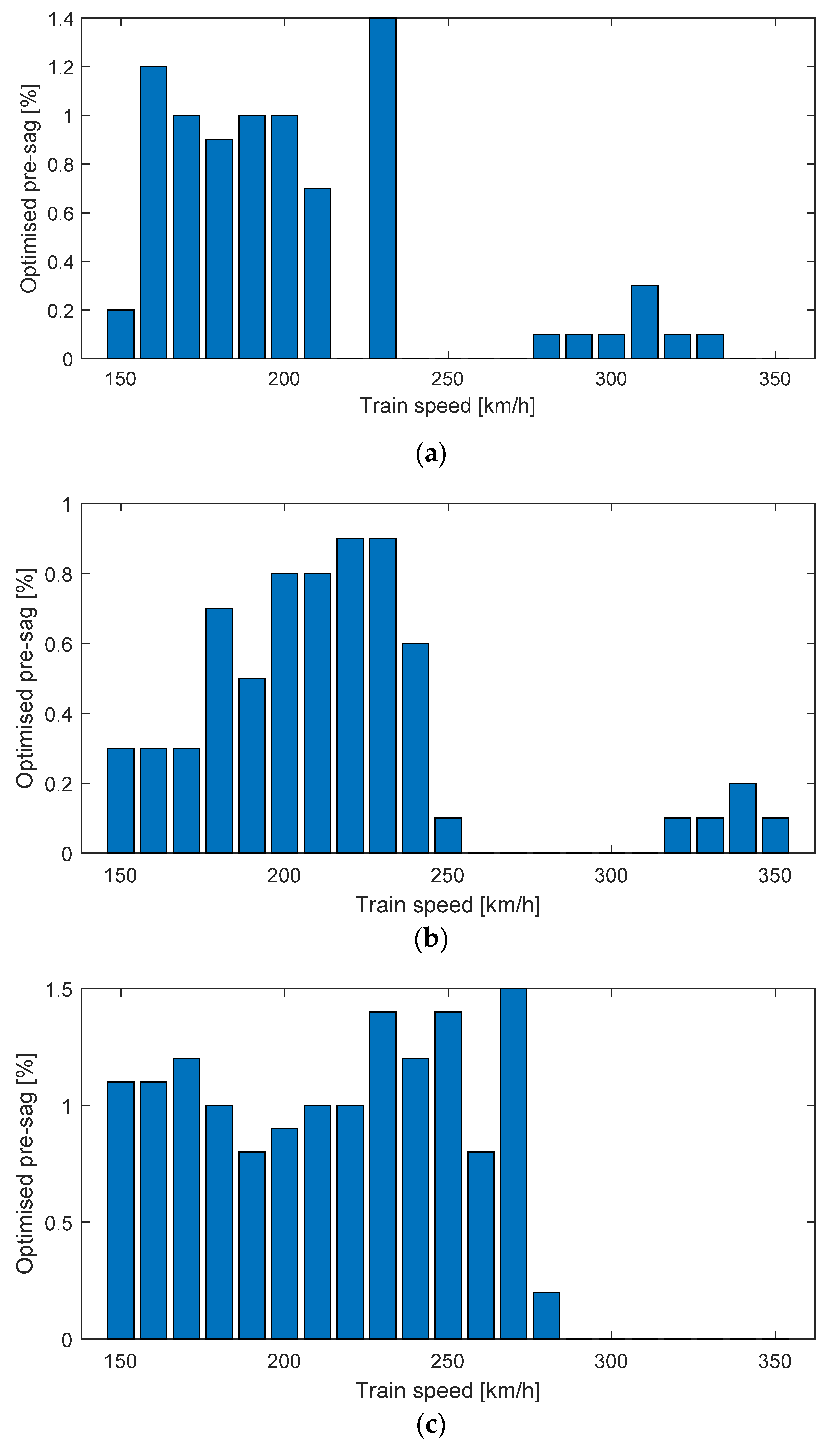
This section implements a generic optimisation procedure to make sense of the optimal pre-sag at each train speed. The objective is to minimise the contact force standard deviation. Figure 9a–c presents the optimal pre-sags with the three above-mentioned tension classes. It is obviously seen that in each figure, a large pre-sag is preferred at low speeds. But the analysis in the previous section indicates that the effect of pre-sag can be neglected at low speeds. Therefore, the optimisation at a low-speed range does not have too many practical values. In contrast, the performance at the high-speed range is sensitive to the pre-sag. The optimisation results indicate that a slight amount of pre-sag can benefit the interaction performance. It is also clear that the ‘low-speed range’ increases with the improvement of the tension class. The increase of the tension classes can significantly reduce the sensitivity of the interaction performance to the pre-sag. Particularly, at the tension class of TCW = 31 kN, TMW = 23 kN, no pre-sag is recommended for the high-speed range. The analysis results can provide some references for the industry. The best solution for the current collection quality of the pantograph and overhead contact line is the improvement of tension in the contact line, and no pre-sag needs to be included. However, due to the limitation of material property, the tension in the contact line cannot be infinite. A slight pre-sag can help to maintain a good interaction performance at high speed.
5. Discussion
In current industries, there are generally two approaches to compensate for the unevenness of elasticity. One approach is to include stitch wires to reduce the stiffness around the steady arm. The other is to set pre-sag for the contact line. In most high-speed networks, the pre-sag of the contact line is set to 0.5‰ to enable the high-speed train at around 300 km/h [60]. According to the analysis in this work, this amount of pre-sag can be slightly reduced to ensure optimal results. It is also recommended that the set of pre-sag should be cautious at high-speed, because extra pre-sag can lead to significant deterioration of the current collection quality. It is a little unexpected that the measure of including pre-sag cannot improve the current collection quality any more at speeds above 350 km/h. That is why there is no application of the overhead contact line without stitch wires at 350 km/h around the world. The finding of this work is generally consistent with the current industrial application. The inclusion of stitch wires is necessary for developing the high-speed railway, especially at speeds above 350 km/h.
6. Conclusions
This work attempts to quantify the effect of contact line pre-sag on interaction performance. Taking a classic high-speed rail overhead contact line system as the analysis object, the overhead contact line models with different pre-sags are built via a nonlinear finite element approach. Through a number of dynamic simulations, the effect of pre-sag on the contact force is analysed with different train speeds and tension classes. The analysis result indicates the feasibility of tuning the pre-sag to improve the interaction performance at a given speed and tension class. In the low-speed range, the change of pre-sag does not have a significant effect on interaction performance. However, when the speed increases up to a certain value, the effect of the contact line pre-sag on the contact force is nonnegligible. The increase in tension can reduce the sensitivity of the interaction performance to the pre-sag. The optimal results of the contact line pre-sag can provide a reference for the rail industry. Due to the limitation of material property, the tension in the contact line cannot be infinite. A slight pre-sag can help maintain a good high-speed interaction performance.
The future work will be conducted from two main aspects. The first one is to quantify the effect of pre-sag on the contact force with more complex working conditions, such as curves and steep slopes. The second one is to investigate the deterioration of the contact line geometry with more measurement data from the rail operators.
Author Contributions
Conceptualisation, Y.S. and G.M.; methodology, Y.S.; software, Y.S.; validation, G.M. and Y.S.; formal analysis, Y.S.; investigation, Y.S.; resources, Y.S. and G.M.; writing—original draft preparation, Y.S.; writing—review and editing, G.M.; funding acquisition, Y.S and G.M. All authors have read and agreed to the published version of the manuscript.
Funding
This research was funded by the open project of State Key Laboratory of Traction Power, grant number TPL2211.
Institutional Review Board Statement
Not applicable.
Informed Consent Statement
Not applicable.
Data Availability Statement
Not applicable.
Conflicts of Interest
The authors declare no conflict of interest.
References
- EN 50119; Railway Applications—Fixed Installations—Electric Traction Overhead Contact Lines. European Standards (EN): Brussels, Belgium, 2015.
- Li, Y.; Jin, T.; Liu, L.; Yuan, K. Dynamic Performance Simulation and Stable Current Collection Analysis of a Pantograph Catenary System for Trolley Wire Overhead Electrically Actuated LHD. Energies 2020, 13, 1015. [Google Scholar] [CrossRef]
- Avila-Sanchez, S.; Lopez-Garcia, O.; Cuerva, A.; Meseguer, J. Assesment of the transverse galloping stability of a railway overhead located above a railway bridge. Int. J. Mech. Sci. 2017, 131–132, 649–662. [Google Scholar] [CrossRef]
- Song, Y.; Zhang, M.; Øiseth, O.; Rønnquist, A. Wind deflection analysis of railway catenary under crosswind based on nonlinear finite element model and wind tunnel test. Mech. Mach. Theory 2022, 168, 104608. [Google Scholar] [CrossRef]
- Song, Y.; Zhang, M.; Wang, H. A response spectrum analysis of wind deflection in railway overhead contact lines using pseudo-excitation method. IEEE Trans. Veh. Technol. 2021, 70, 1169–1178. [Google Scholar] [CrossRef]
- Zhang, M.; Song, Y.; Abdelkefi, A.; Yu, H.; Wang, J. Vortex-induced vibration of a circular cylinder with nonlinear stiffness: Prediction using forced vibration data. Nonlinear Dyn. 2022, 108, 1867–1884. [Google Scholar] [CrossRef]
- Song, Y.; Wang, Z.; Liu, Z.; Wang, R. A spatial coupling model to study dynamic performance of pantograph-catenary with vehicle-track excitation. Mech. Syst. Signal Process. 2021, 151, 107336. [Google Scholar] [CrossRef]
- Ye, Y.; Zhu, B.; Huang, P.; Peng, B. OORNet: A deep learning model for on-board condition monitoring and fault diagnosis of out-of-round wheels of high-speed trains. Meas. J. Int. Meas. Confed. 2022, 199, 111268. [Google Scholar] [CrossRef]
- Ye, Y.; Huang, P.; Sun, Y.; Shi, D. MBSNet: A deep learning model for multibody dynamics simulation and its application to a vehicle-track system. Mech. Syst. Signal Process. 2021, 157, 107716. [Google Scholar] [CrossRef]
- Song, Y.; Liu, Z.; Duan, F.; Xu, Z.; Lu, X. Wave propagation analysis in high-speed railway catenary system subjected to a moving pantograph. Appl. Math. Model. 2018, 59, 20–38. [Google Scholar] [CrossRef]
- Song, Y.; Duan, F. Performance assessment of pantograph and overhead system based on a vertical coupling dynamics model of the railway system. Complex Eng. Syst. 2022, 2, 9. [Google Scholar] [CrossRef]
- Mariscotti, A.; Sandrolini, L. Detection of harmonic overvoltage and resonance in AC railways using measured pantograph electrical quantities. Energies 2021, 14, 5645. [Google Scholar] [CrossRef]
- Wang, J.; Yang, Z.; Lin, F.; Cao, J. Harmonic Loss Analysis of the Traction Transformer of High-Speed Trains Considering Pantograph-OCS Electrical Contact Properties. Energies 2013, 6, 5826–5846. [Google Scholar] [CrossRef]
- Calleja-Duro, V.; Fernández-Díaz, R.Á.; Barreiro-García, J.; Calvo-Hernández, Á. Desarrollo y ensayo de un amortiguador de masas sintonizadas para sistemas de catenaria rígida. DYNA 2017, 92, 680–687. [Google Scholar] [CrossRef]
- Gao, G.; Hao, J.; Wei, W.; Hu, H.; Zhu, G.; Wu, G. Dynamics of Pantograph-Catenary Arc during the Pantograph Lowering Process. IEEE Trans. Plasma Sci. 2016, 44, 2715–2723. [Google Scholar] [CrossRef]
- Song, Y.; Jiang, T.; Nåvik, P.; Rønnquist, A. Geometry deviation effects of railway catenaries on pantograph–catenary interaction: A case study in Norwegian Railway System. Railw. Eng. Sci. 2021, 29, 350–361. [Google Scholar] [CrossRef]
- Song, Y.; Liu, Z.; Ronnquist, A.; Navik, P.; Liu, Z. Contact wire irregularity stochastics and effect on high-speed railway pantograph-catenary interactions. IEEE Trans. Instrum. Meas. 2020, 69, 8196–8206. [Google Scholar] [CrossRef]
- Chen, H.; Jiang, B. A Review of Fault Detection and Diagnosis for the Traction System in High-Speed Trains. IEEE Trans. Intell. Transp. Syst. 2020, 21, 450–465. [Google Scholar] [CrossRef]
- Gao, S. Automatic Detection and Monitoring System of Pantograph-Catenary in China’s High-Speed Railways. IEEE Trans. Instrum. Meas. 2021, 70, 3502012. [Google Scholar] [CrossRef]
- Liu, Z.; Liu, W.; Han, Z. A high-precision detection approach for catenary geometry parameters of electrical railway. IEEE Trans. Instrum. Meas. 2017, 66, 1798–1808. [Google Scholar] [CrossRef]
- Liu, W.; Liu, Z.; Li, Q.; Han, Z.; Nunez, A. High-Precision Detection Method for Structure Parameters of Catenary Cantilever Devices Using 3-D Point Cloud Data. IEEE Trans. Instrum. Meas. 2021, 70, 3507811. [Google Scholar] [CrossRef]
- Liu, W.; Liu, Z.; Li, Y.; Wang, H.; Yang, C.; Wang, D.; Zhai, D. An automatic loose defect detection method for catenary bracing wire components using deep convolutional neural networks and image processing. IEEE Trans. Instrum. Meas. 2021, 70, 5016814. [Google Scholar] [CrossRef]
- Wei, X.; Jiang, S.; Li, Y.; Li, C.; Jia, L.; Li, Y. Defect detection of pantograph slide based on deep learning and image processing technology. IEEE Trans. Intell. Transp. Syst. 2020, 21, 947–958. [Google Scholar] [CrossRef]
- Chen, J.; Liu, Z.; Wang, H.; Nunez, A.; Han, Z. Automatic defect detection of fasteners on the catenary support device using deep convolutional neural network. IEEE Trans. Instrum. Meas. 2018, 67, 257–269. [Google Scholar] [CrossRef]
- Luo, L.; Ye, W.; Wang, J. Defect detection of the puller bolt in high-speed railway catenary based on deep learning. J. Railw. Sci. Eng. 2021, 18, 605–614. [Google Scholar] [CrossRef]
- Cheng, H.; Wang, J.; Liu, J.; Cao, Y.; Li, H.; Xu, X. Comprehensive evaluation method of catenary status based on improved multivariate statistical control chart. J. Railw. Sci. Eng. 2021, 18, 3048–3056. [Google Scholar] [CrossRef]
- Bruni, S.; Ambrosio, J.; Carnicero, A.; Cho, Y.H.; Finner, L.; Ikeda, M.; Kwon, S.Y.; Massat, J.P.; Stichel, S.; Tur, M.; et al. The results of the pantograph-catenary interaction benchmark. Veh. Syst. Dyn. 2015, 53, 412–435. [Google Scholar] [CrossRef]
- Wu, T.X.; Brennan, M.J. Dynamic stiffness of a railway overhead wire system and its effect on pantograph-catenary system dynamics. J. Sound Vib. 1999, 219, 483–502. [Google Scholar] [CrossRef]
- Poetsch, G.; Evans, J.; Meisinger, R.; Kortüm, W.; Baldauf, W.; Veitl, A.; Wallaschek, J. Pantograph/catenary dynamics and control. Veh. Syst. Dyn. 1997, 28, 159–195. [Google Scholar] [CrossRef]
- Vesali, F.; Rezvani, M.A.; Molatefi, H. Analysis of conceptual similarities and differences of wave speed and critical speed in the overhead catenary system. Measurement 2021, 176, 109164. [Google Scholar] [CrossRef]
- Song, Y.; Duan, F.; Liu, Z. Analysis of Critical Speed for High-Speed Railway Pantograph-Catenary System. IEEE Trans. Veh. Technol. 2022, 71, 3547–3555. [Google Scholar] [CrossRef]
- Song, Y.; Rønnquist, A.; Nåvik, P. Assessment of the high-frequency response in railway pantograph-catenary interaction based on numerical simulation. IEEE Trans. Veh. Technol. 2020, 69, 10596–10605. [Google Scholar] [CrossRef]
- Pappalardo, C.M.; Patel, M.D.; Tinsley, B.; Shabana, A.A. Contact force control In multibody pantograph/catenary systems. Proc. Inst. Mech. Eng. Part K J. Multi-Body Dyn. 2016, 230, 307–328. [Google Scholar] [CrossRef]
- Chu, W.; Song, Y. Study on Dynamic Interaction of Railway Pantograph–Catenary Including Reattachment Momentum Impact. Vibration 2020, 3, 18–33. [Google Scholar] [CrossRef]
- Zhang, W.H.; Mei, G.M.; Wu, X.J.; Chen, L.Q. A study on dynamic behaviour of pantographs by using hybrid simulation method. Proc. Inst. Mech. Eng. Part F J. Rail Rapid Transit 2005, 219, 189–199. [Google Scholar] [CrossRef]
- Song, Y.; Antunes, P.; Pombo, J.; Liu, Z. A methodology to study high-speed pantograph-catenary interaction with realistic contact wire irregularities. Mech. Mach. Theory 2020, 152, 103940. [Google Scholar] [CrossRef]
- Bautista, A.; Montesinos, J.; Pintado, P. Dynamic interaction between pantograph and rigid overhead lines using a coupled FEM—Multibody procedure. Mech. Mach. Theory 2016, 97, 100–111. [Google Scholar] [CrossRef]
- Kim, J.W.; Chae, H.C.; Park, B.S.; Lee, S.Y.; Han, C.S.; Jang, J.H. State sensitivity analysis of the pantograph system for a high-speed rail vehicle considering span length and static uplift force. J. Sound Vib. 2007, 303, 405–427. [Google Scholar] [CrossRef]
- Lu, X.; Liu, Z.; Zhang, J.; Wang, H.; Song, Y.; Duan, F. Prior-Information-Based Finite-Frequency H∞ Control for Active Double Pantograph in High-Speed Railway. IEEE Trans. Veh. Technol. 2017, 66, 8723–8733. [Google Scholar] [CrossRef]
- Lu, X.; Liu, Z.; Song, Y.; Wang, H.; Zhang, J.; Wang, Y. Estimator-based multiobjective robust control strategy for an active pantograph in high-speed railways. Proc. Inst. Mech. Eng. Part F J. Rail Rapid Transit 2018, 232, 1064–1077. [Google Scholar] [CrossRef]
- Vera, C.; Suarez, B.; Paulin, J.; Rodríguez, P. Simulation model for the study of overhead rail current collector systems dynamics, focused on the design of a new conductor rail. Veh. Syst. Dyn. 2006, 44, 595–614. [Google Scholar] [CrossRef] [Green Version]
- EN 50367; Railway Applications—Current Collection Systems—Technical Criteria for the Interaction between Pantograph and Overhead Line. European Standards (EN): Brussels, Belgium, 2016.
- Song, Y.; Ouyang, H.; Liu, Z.; Mei, G.; Wang, H.; Lu, X. Active control of contact force for high-speed railway pantograph-catenary based on multi-body pantograph model. Mech. Mach. Theory 2017, 115, 35–59. [Google Scholar] [CrossRef]
- Zdziebko, P.; Martowicz, A.; Uhl, T. An investigation on the active control strategy for a high-speed pantograph using co-simulations. Proc. Inst. Mech. Eng. Part I J. Syst. Control Eng. 2019, 233, 370–383. [Google Scholar] [CrossRef]
- Ambrósio, J.; Pombo, J.; Pereira, M. Optimization of high-speed railway pantographs for improving pantograph-catenary contact. Theor. Appl. Mech. Lett. 2013, 3, 013006. [Google Scholar] [CrossRef]
- Di Stefano, E.; Avizzano, C.A.; Bergamasco, M.; Masini, P.; Menci, M.; Russo, D. Automatic inspection of railway carbon strips based on multi-modal visual information. In Proceedings of the 2017 IEEE International Conference on Advanced Intelligent Mechatronics (AIM), Munich, Germany, 3–7 July 2017; pp. 178–184. [Google Scholar] [CrossRef]
- Zhu, M.; Zhang, S.Y.; Jiang, J.Z.; Macdonald, J.; Neild, S.; Antunes, P.; Pombo, J.; Cullingford, S.; Askill, M.; Fielder, S. Enhancing pantograph-catenary dynamic performance using an inertance-integrated damping system. Veh. Syst. Dyn. 2021, 60, 1909–1932. [Google Scholar] [CrossRef]
- Song, Y.; Liu, Z.; Duan, F.; Lu, X.; Wang, H. Study on wind-induced vibration behavior of railway catenary in spatial stochastic wind field based on nonlinear finite element procedure. J. Vib. Acoust. Trans. ASME 2018, 140, 011010. [Google Scholar] [CrossRef]
- Song, Y.; Liu, Z.; Wang, H.; Lu, X.; Zhang, J. Nonlinear analysis of wind-induced vibration of high-speed railway catenary and its influence on pantograph–catenary interaction. Veh. Syst. Dyn. 2016, 54, 723–747. [Google Scholar] [CrossRef]
- Song, Y.; Duan, F.; Gao, S.; Wu, F.; Liu, Z. Crosswind Effects on Current Collection Quality of Railway Pantograph-catenary: A Case Study in Chengdu-Chongqing Passenger Special Line. IEEE Trans. Instrum. Meas. 2021, 71, 9000713. [Google Scholar] [CrossRef]
- Stickland, M.T.; Scanlon, T.J.; Craighead, I.A.; Fernandez, J. An investigation into the mechanical damping characteristics of catenary contact wires and their. Proc. Inst. Mech. Eng. Part F J. Rail Rapid Transit 2001, 217, 63–72. [Google Scholar] [CrossRef]
- Zhang, Y.; Yue, Y.; Zhao, S.; Sihua, W. Research on galloping response of catenary positive feeder in gale area considering surface roughness of stranded wire. J. Railw. Sci. Eng. 2021, 18, 1885–1894. [Google Scholar] [CrossRef]
- Song, Y.; Liu, Z.; Wang, H.; Zhang, J.; Lu, X.; Duan, F. Analysis of the galloping behaviour of an electrified railway overhead contact line using the non-linear finite element method. Proc. Inst. Mech. Eng. Part F J. Rail Rapid Transit 2018, 232, 2339–2352. [Google Scholar] [CrossRef]
- Zhai, W.M.; Cai, C.B. Effect of locomotive vibrations on pantograph-catenary system dynamics. Veh. Syst. Dyn. 1998, 29, 47–58. [Google Scholar] [CrossRef]
- Yao, Y.; Zhou, N.; Mei, G.; Zhang, W. Dynamic Analysis of Pantograph-Catenary System considering Ice Coating. Shock Vib. 2020, 2020, 8887609. [Google Scholar] [CrossRef]
- Song, Y.; Liu, Z.; Lu, X. Dynamic Performance of High-Speed Railway Overhead Contact Line Interacting with Pantograph Considering Local Dropper Defect. IEEE Trans. Veh. Technol. 2020, 69, 5958–5967. [Google Scholar] [CrossRef]
- Vesali, F.; Rezvani, M.A.; Molatefi, H.; Hecht, M. Static form-finding of normal and defective catenaries based on the analytical exact solution of the tensile Euler–Bernoulli beam. Proc. Inst. Mech. Eng. Part F J. Rail Rapid Transit 2019, 233, 691–700. [Google Scholar] [CrossRef]
- Van, O.V.; Massat, J.P.; Laurent, C.; Balmes, E. Introduction of variability into pantograph-catenary dynamic simulations. Veh. Syst. Dyn. 2014, 52, 1254–1269. [Google Scholar] [CrossRef]
- Cho, Y.H.; Lee, K.; Park, Y.; Kang, B.; Kim, K.N. Influence of contact wire pre-sag on the dynamics of pantographrailway catenary. Int. J. Mech. Sci. 2010, 52, 1471–1490. [Google Scholar] [CrossRef]
- Kiessling, F.; Puschmann, R.; Schmieder, A.; Schneider, E. Contact Lines for Electric Railways, 3rd ed.; John Wiley & Sons: Hoboken, NJ, USA, 2018; Volume 116, ISBN 3-8957-152-5. [Google Scholar]
- Qin, R.; Zhu, B.; Qiao, K.; Wang, D.; Sun, N.; Yuan, X. Simulation study of the protective performance of composite structure carbon fiber bulletproof board. Chin. J. Eng. 2021, 43, 1346–1354. [Google Scholar] [CrossRef]
- Wang, C.; Zhang, Q.; Li, H.; Zhang, L.; Zhang, B. Warpage deformation behavior of metal laminates. Chin. J. Eng. 2021, 43, 409–421. [Google Scholar] [CrossRef]
- Shabana, A.A. Definition of ANCF Finite Elements. J. Comput. Nonlinear Dyn. 2015, 10, 054506. [Google Scholar] [CrossRef]
- Pil Jung, S.; Guk Kim, Y.; Sung Paik, J.; Won Park, T. Estimation of dynamic contact force between a pantograph and catenary using the finite element method. J. Comput. Nonlinear Dyn. 2012, 7, 041006. [Google Scholar] [CrossRef]
- Song, Y.; Rønnquist, A.; Jiang, T.; Nåvik, P. Identification of short-wavelength contact wire irregularities in electrified railway pantograph–catenary system. Mech. Mach. Theory 2021, 162, 104338. [Google Scholar] [CrossRef]
- Song, Y.; Liu, Z.; Wang, H.; Lu, X.; Zhang, J. Nonlinear modelling of high-speed catenary based on analytical expressions of cable and truss elements. Veh. Syst. Dyn. 2015, 53, 1455–1479. [Google Scholar] [CrossRef]
Figure 1.
Overhead contact line and pantograph system: (a) Overhead contact line; (b) Pantograph.
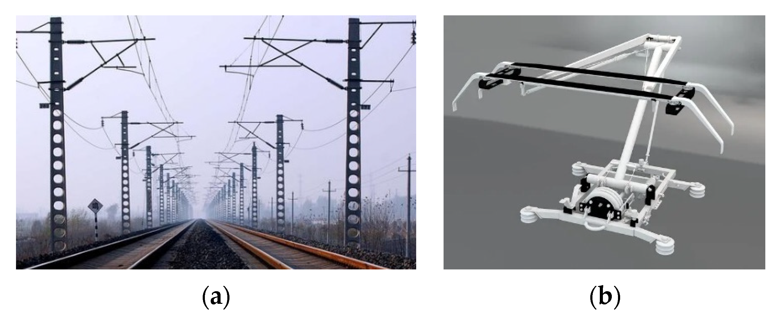
Figure 2.
Schematics of an overhead contact line system with pre-sag.

Figure 3.
Numerical model of overhead contact line and pantograph.
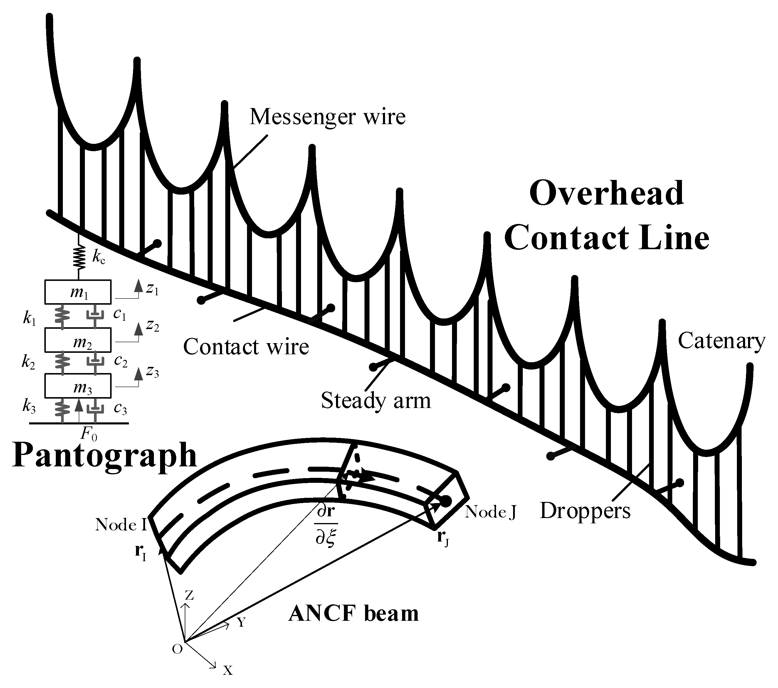
Figure 4.
Geometry of contact line with different pre-sags.
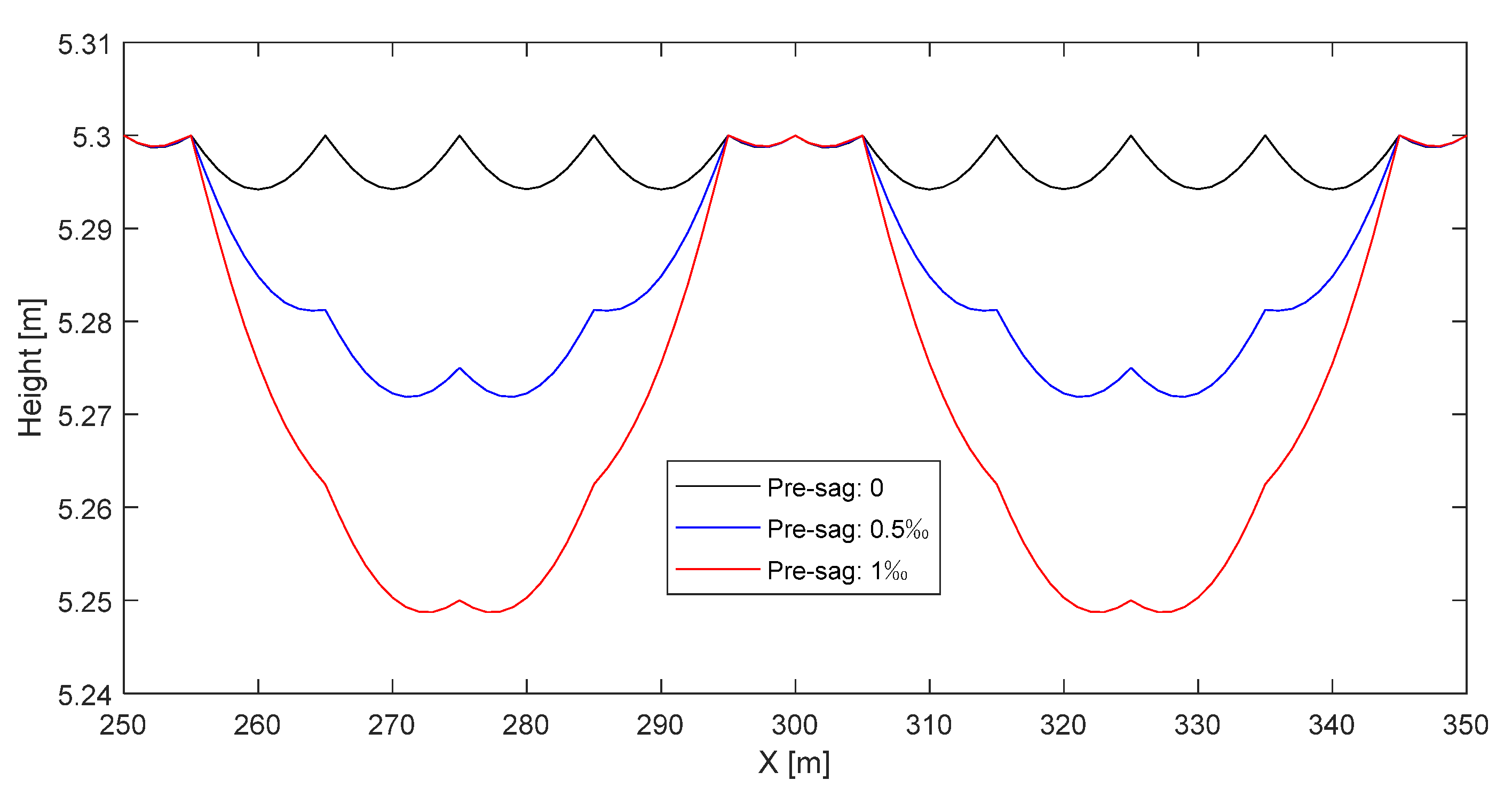
Figure 5.
Contact force standard deviation with different pre-sags and train speeds.
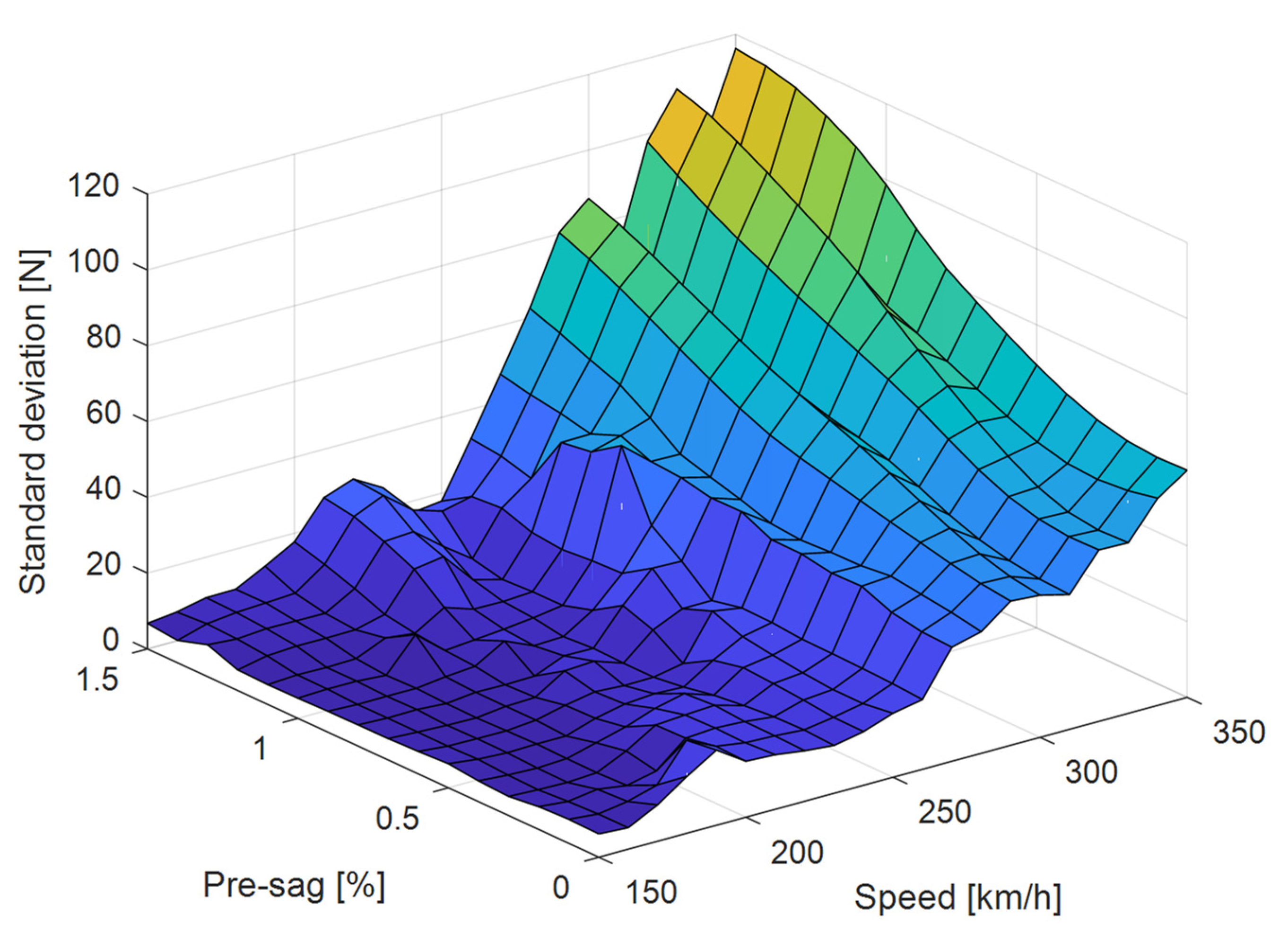
Figure 6.
Contact forces with different pre-sags at the speed of 330 km/h.

Figure 7.
Contact force standard deviation with different pre-sags and train speeds (TCW = 23 kN, TMW = 17 kN).
Figure 7.
Contact force standard deviation with different pre-sags and train speeds (TCW = 23 kN, TMW = 17 kN).

Figure 8.
Contact force standard deviation with different pre-sags and train speeds (TCW = 31 kN, TMW = 23 kN).
Figure 8.
Contact force standard deviation with different pre-sags and train speeds (TCW = 31 kN, TMW = 23 kN).

Figure 9.
Optimised pre-sag at different train speeds with (a) TCW = 23 kN, TMW = 17 kN; (b) TCW = 27 kN, TMW = 20 kN; (c) TCW = 31 kN, TMW = 23 kN.
Figure 9.
Optimised pre-sag at different train speeds with (a) TCW = 23 kN, TMW = 17 kN; (b) TCW = 27 kN, TMW = 20 kN; (c) TCW = 31 kN, TMW = 23 kN.

Table 1.
Main parameters of overhead contact line system.
| Material Property | |
|---|---|
| Contact line | Line density: 1.082 kg/m; Tensile rigidity: 106 N/m; Tension: 27 kN; Cross-section: 120 mm2 |
| Messenger line | Line density: 1.068 kg/m; Tensile rigidity: 106 N/m; Tension: 20 kN; Cross-section: 120 mm2 |
| Dropper | Line density: 0.14 kg/m; Tensile rigidity: 105 N/m |
| Geometrical Property | |
| Span length: 50 m; Encumbrance: 1.6 m; Droppers interval: 10 m; Number of droppers: 5; Span number: 15 | |
Publisher’s Note: MDPI stays neutral with regard to jurisdictional claims in published maps and institutional affiliations. |
© 2022 by the authors. Licensee MDPI, Basel, Switzerland. This article is an open access article distributed under the terms and conditions of the Creative Commons Attribution (CC BY) license (https://creativecommons.org/licenses/by/4.0/).
Share and Cite
MDPI and ACS Style
Mei, G.; Song, Y. Effect of Overhead Contact Line Pre-Sag on the Interaction Performance with a Pantograph in Electrified Railways. Energies 2022, 15, 6875. https://doi.org/10.3390/en15196875
AMA Style
Mei G, Song Y. Effect of Overhead Contact Line Pre-Sag on the Interaction Performance with a Pantograph in Electrified Railways. Energies. 2022; 15(19):6875. https://doi.org/10.3390/en15196875
Chicago/Turabian StyleMei, Guiming, and Yang Song. 2022. "Effect of Overhead Contact Line Pre-Sag on the Interaction Performance with a Pantograph in Electrified Railways" Energies 15, no. 19: 6875. https://doi.org/10.3390/en15196875
Note that from the first issue of 2016, this journal uses article numbers instead of page numbers. See further details here.