1. Introduction
Recently, the interest in fuel cells has grown more than ever due to the need for sustainable energy [
1]. In a fuel cell, the fuel is converted electrochemically into electricity by oxygen-reduction reactions (ORRs) and hydrogen-oxidation reactions (HORs) [
2]. Most automotive manufacturers develop fuel-cell electric vehicles (FCEVs), with Toyota, Honda, and Hyundai among the most prominent and advanced, with cars and buses made in pre-series numbers (several thousands of units) and becoming commercially available [
3]. Across different types of fuel cell, the operating temperature and type of fuel are of importance to determine the cells’ respective applications. For example, direct methanol fuel cells (DMFCs) operates using methanol or ethanol as fuel, while alkaline fuel cells and PEMFCs only operate with hydrogen. Solid oxide fuel cells (SOFCs), which operate at high temperatures, and molten carbonate fuel cells (MCFCs), offer more freedom in terms of the selection of the input fuel, which can be hydrogen, biogas, or natural gas. In low operating temperatures, PEMFCs are particularly attractive because they can offer the same driving range as combustion engines at the same refueling speed (15 times faster than fast-charge batteries) [
4]. The performance level is thus already very high, yet continued significant improvements in durability (lifetime > 5000 h) and reliability (resilience against failures) are needed and sought.
1.1. History and Working Principles
In the mid-1960s, Willard Grubb and Leonard Niedrach invented the PEMFC at General Electric. PEMFCs are firmly established as an alternative of combustion engines to generate power, particularly in transportation [
5]. After delivery to the anode side, fuel steam (hydrogen or highly concentrated hydrogen mixture) catalytically forms protons and electrons via a hydrogen-oxidation reaction (
[
6]. The generated protons migrate to the cathode side through the membrane and react with oxygen to produce water and heat as a byproduct
[
7].
Figure 1 presents a schematic of the repetitive unit with its different layers. PEMFCs have several unique advantages, e.g., high power densities, negligible emissions, and silent operation, and can be deployed even in remote areas.
Table 1 represents some of the significant milestones in PEMFCs’ technology and applications since their infancy.
1.2. Applications and Current Status
The NASA Gemini earth-orbiting mission (1962 to 1965) was the first project using PEMFC as the primary power source for space flights [
19]. While significant improvements were made in the 1970s and 1980s in the performance of PEMFCs (particularly through the introduction of Nafion
® membranes [
20]), this concept remained dormant until 1993, when the USA Partnership for a New Generation of Vehicles (PNGV) program comprehensively reported the potential applications of PEMFCs in transportation [
21]. Since then, major enterprises have initiated projects featuring the implementation of PEMFCs in their vehicles. The results were demonstrated in 2005, when Daimler–Chrysler, Hyundai, and GM participated in a 6-hour rally in Monaco with their first commercialized, on-board, PEMFC-driven vehicles [
17]. At this stage, the hydrogen-based vehicle industry, with 7000 fuel-cell-based vehicles sold in the United States so far [
22], is still in its early stage, and the market is still dominated by gasoline cars. However, PEMFCs’ low temperature requirements, low levels of greenhouse-gas pollution, compact sizes, and high power density make them excellent candidates to replace internal combustion engines [
23].
Figure 2 shows the output of greenhouse-gas emissions by different technologies that have been implemented in vehicles [
24]. Notably,
Figure 2 presents projected data of greenhouse gas pollution from 2022 to 2100.
The success of the Hyundai Tucson FCEV and Hyundai Nexo has encouraged the US Department of Energy (DOE) and cabinet-level ministries of European countries to invest more in PEMFCs for hydrogen-fuel-cell vehicles. The major milestone in the implementation of PEMFCs in vehicles was initiated by Toyota MIRAI, who, in 2008, first released 100 such cars worldwide; these cars were officially debuted in December 2014, at a price of JPY 7 million, equivalent to USD 57,500. By improving the PEMFCs, the current Toyota MIRAI was, optimized with 2.4 times higher current density and an enhancement in its oxygen reduction reaction activity by a factor of 1.8. This was mainly due to the implementation of solid-core-type support rather than conventional hollow-carbon support, allowing the more efficient utilization of the Pt catalyst [
26]. While the performance level is already high, continuous significant improvements in durability (lifetime > 5000 h) and reliability (resilience against failures) are still yet to be explored, although PEMFCs at the end of life can be disassembled and recycled (see
Table 2). The lifespan of PEMFCs is 5000 h when they are used as the primary power sources for passenger vehicles. For stationary power sources, the lifetime can reach 30,000 h. This disparity is usually attributed to the complex operating conditions of PEMFC-based cars, such as frequent switches between on and off, charge and discharge, etc. [
27]. Load changing, followed by starting and stopping, high power, and idling, are considered the leading causes of the high levels of performance degradation in vehicles [
28].
The vehicular application of PEMFCs is not only limited to cars. Many theoretical studies have been conducted on the use of PEMFC-driven buses for a “greener” environment (e.g., [
29]).
Figure 3 demonstrates the different components of the PEMFC and the integration of these components to create a PEMFC system.
Figure 3 also illustrates the vehicular integration of fuel cells in different sectors. Commercially, Turin and Madrid Transit Buses began using UTC 60-kilowatt hybrid buses in 2000. Later, Delijn (Belgium) developed a higher-power (120-kilowatt) hybrid bus from UTC in their transportation systems. Sao Paulo and Beijing have also incorporated Ballard PEM fuel-cell stacks in their services since 2005. Currently, there are 20 active buses in the USA that are operated entirely by PEMFCs, and the roadmap shows that this number will rise to 200 by 2025 [
30]. The UK is also becoming a pioneer in the development of PEMFC-based buses in its transit system to reduce pollution [
31].
Table 2.
The recycling process of PEMFCs at the end of life [
32].
Table 2.
The recycling process of PEMFCs at the end of life [
32].
| Step | Process | Recycling | Disposing |
|---|
| 1 | Disassembly of balance of plant | - (1)
Humidifier - (2)
Other parts: radiator, pump, etc.
| |
| 2 | Disassembly of stack | Propylene stack housing | |
| 3 | Removal of compression bands and end plates | - (1)
End plates and current collectors
| Compression bands |
| 4 | Singulation of the unit cells (by heating in water) | | |
| 5 | Removal of bipolar plates, corrosion-resistants and conductive coatings | - (1)
Corrosion-resistant and conductive coatings - (2)
Bipolar plates
| |
| 6 | Shredding of membrane electrode assembly (MEA) | | |
| 7 | Dissolution of platinum (Pt) catalyst from MEA | | |
| 8 | Separation of Pt from catalyst layers and diffusion layers | Pt catalyst | - (1)
Gaskets and diffusion layers - (2)
Perfluorosulfonic acid (PFSA)
|
PEMFCs’ implementation in marine transportation is another application that has increased in recent years [
33]. The initial attempt was by MTU Friedrichshafen GmbH, in 2003, which used PEMFC for the propulsion of a 12-meter yacht. The system was driven by four 1.2-kW PEMFC modules and nine lead-gel batteries, which were able to generate 20 kW of power [
34]. Five years later, the world’s first PEMFC-driven ship (FCS Alsterwasser) entered service in Hamburg, and transported 100 passengers at a speed of 14 km/h [
35]. While some other investigations have been conducted recently, the worldwide application of PEMFCs as primary power sources for marine vehicles is yet to be explored.
Figure 3.
Different components used in PEMFCs and the vehicular applications in different sectors [
36].
Figure 3.
Different components used in PEMFCs and the vehicular applications in different sectors [
36].
1.3. Technological Obstacles and Commercialization
The high system cost is one of the main obstacles to the commercialization of PEMFCs, with the bipolar plate (BP) contributing the most after the catalyst layers [
37]. Modifying the geometrical design (mesh [
38], lung-like [
39], serially connected serpentine channels [
40]) can reduce the cost of conventional BPs, but may cause higher pressure drops, low efficiency for low gas-flow rates, or uneven distributions of density [
41]. Anticorrosion coating [
42] (used in MIRAI 2014) and hydroforming [
43] are other approaches to reducing the capital cost associated with BP. Additionally, the cost of the membrane-electrode assembly, system integration, and the assembly of the stack and its components, also needs to be significantly reduced [
44].
Figure 4 shows the shares of different components in the overall cost of the fuel-cell stack, indicating 28% for the bipolar plates. The Balance of Plant (BoP), which is a common term in PEMFC systems and refers to all the auxiliary components of a PEMFC, also determines 10% of the overall cost of a PEMFC stack.
Stack durability is another obstacle to the general use of PEMFCs in industry [
46]. PGM-free cathode catalysts are highly unstable in acidic mediums [
47], and Pt catalysts face other challenges (e.g., sintering [
28] and dissolution [
22]) during long-term operation. The design of the sealings and compression kits can efficiently improve the durability of PEMFCs by reducing the mechanical stresses. Corrosion can also be reduced by preventing the contamination of cells with different types of impurities to enhance their lifetimes.
Furthermore, current PEMFC technology suffers from low stack-power density. The cell level faces significant losses in cathode activation, high resistance of oxygen transport, and electrical electrode/electrolyte contact [
44]. The stack level is further affected by the cooling system and the fabrication of novel BPs; thus, studies are also ongoing to fabricate thinner and more efficient BPs [
48].
1.4. Novelties of the Current Study
So far, a wide range of topics related to the PEMFC has been covered by recent reviews, mostly relating to the characterization methods of the catalyst layer (CL) [
49] and gas-diffusion layer (GDL) [
50]. Arif et al. [
51] presented different types of developed models, ranging from one-dimensional to three-dimensional, to simulate PEMFCs; however, their review mostly covered existing models rather than a systematic approach to model degradation in PEMFCs. All the possible control strategies of PEMFCs have been evaluated by Daud et al. [
52]. Analytical models to investigate the cold start of PEMFCs have been reviewed by Luo et al. [
53], while Xu et al. [
54] analyzed the gas purge in detail. A lifecycle assessment, along with evaluations of the carbon corrosion and the contamination of PEMFCs, were presented in detail by Hua et al. [
55], Zhao et al. [
56], and Zhao et al. [
57], respectively. Although there have been detailed reviews on single types of contamination in PEMFCs, a comprehensive study introducing all the possible types of contamination in the PEMFC system is still needed. For example, Valdés-López et al. [
58] only described carbon monoxide poisoning and strategies to prevent it.
Despite all the efforts to review PEMFCs, there is no comprehensive study covering the effects of the parameters on the long-term performances of PEMFCs with a specific focus on the protective coatings of the BP, the design of the sealing and compression kits, and contamination. Furthermore, fundamental theory and governing equations to model the degradation are either missing or deficient. The focus of this study is on introducing advanced protective coatings for bipolar plates to enhance the long-term performances of PEMFCs. The theoretical formulation of the degradation is presented to facilitate the development of a model to monitor the performance. Different types of contamination are also described as important parameters to increase the lifetime of the stacks. The four main types of sealings to prevent the leakage of the reactants/products and reduce the compression forces are also explained.
This study offers a powerful introduction to the technology for researchers in different fields who are approaching this technology for the first time, or for industrial/academic experts who want to implement new methods to enhance the lifetimes of PEMFCs. This study also provides all the necessary governing equations and different analytical models to formulate the degradation of PEMFCs while considering the recent advances in technology to improve their commercialization.
2. Quasi-2D Model of a Fuel Cell
The long-term performance of a PEMFC can be analyzed using either experimental or numerical methods. In this regard, a comprehensive numerical model is needed to characterize the degradation waves that may affect the performance of the PEMFC in long-term conditions. The aim of this section is to review and suggest an efficient model based on different references to facilitate the numerical degradation modeling of PEMFCs.
The quasi-2D model of the PEMFC calculates the changes in the concentrations, overpotentials, current densities, etc., along the gas-flow channel, which distributes the reactants over the cell [
59]. In reality, one-dimensional models are not able to capture the non-homogeneity in the reactants and water concentrations along the channel, resulting in voltage losses.
As the lengths of the channels are much higher than the MEA’s thickness, the fluxes in the z-direction, shown in
Figure 1, are negligible. Hence, the transport of protons in the MEA occurs in the x-direction, while that of the reactants occurs in the z-direction in the flow channels. In this regard, the 2D problem should be divided into two 1D problems; hence, a quasi-2D (or 1D + 1D) approach is used to obtain the concentrations and local current density.
2.1. Momentum Conservation
The flow in the gas-flow channels of the PEMFC is a Poiseuille flow at the constant velocity determined by the pressure gradient,
(Pa). It is assumed that the channel’s walls are impermeable and the flow velocity,
(cm/s), changes as a result of mass and momentum transfer at the GDL/channel interface. The viscous forces are neglected, in addition to the presence of liquid droplets in the channels. The Euler equation presents the momentum transfer [
36]:
The consumption of the oxygen molecules during the oxygen-reduction reaction (ORR) reduces the cathode-flow momentum and increases the average flow velocity by the addition of the water molecules. Equation (2) updates Equation (1) for the flux of
molecules through the channel/GDL interface [
36]:
where
(kg/
) is the density and h (cm) is the height of a representative volume in the gas-flow channel. Equation (3) considers the effects of water and oxygen in Equation (2) [
36]:
where the subscripts
and
represent the oxygen and water, respectively,
(A/
) is the local current density in the z-direction,
(C/mol) is the Faraday constant, M (kg/mol) is the mean molecular weight, and
is the dimensionless effective-transfer coefficient of water molecules through the MEA.
Combining Equations (1) and (3) [
36]:
Using the gas law
, pressure can be eliminated from Equation (4). Here,
(cm/s) is the speed of the sound and
(
) is the universal gas constant [
36].
Equation (6) is an updated form of Equation (4) [
36]:
Next, subscript z can be omitted as
and pressure gradient can be simplified along the z-direction [
36]:
The first term on the right-hand side of Equation (7) presents the resulting changes in the velocity due to the changes in the flow mass, while the second term indicates the momentum loss at the GDL/channel interface. Equation (8) shows the simplified version of Equation (6) if velocity gradient along the z-direction is removed [
36]:
Hence, Equations (7) and (8) create a system of two non-linear equations to determine the unknown variables of density and velocity. In PEMFC problems, as the velocity is much less than the speed of sound, a solution can be proposed.
2.2. The Low-Velocity Conditions
At low flow velocities (
), the effects of
are more recognizable than those of
; hence, the second terms in the right- and left-hand sides of Equation (7) can be neglected by assuming
, although the derivation of the velocity is not zero and should be calculated using Equation (9) [
60]:
Similarly, Equation (8) changes to [
60]:
Through this simplification, the flow velocity and density can mainly be determined by the mass transfer at the interface of GDL/channel, and the effects of momentum transfer will be small. Using the following dimensionless parameters and the assumption given by Equations (11) and (12), respectively, Equations (9) and (10) change to Equations (13) and (14) [
60].
where
is the inlet velocity, while
is that of the density.
(kg/mol) is also the molecular weight of a hydrogen atom [
60]:
where
is the oxygen molar fraction in the flow (in air
) and
is a parameter needed to calculate the effective water transport coefficient
as follows [
60]:
As a boundary condition at the inlet [
60]:
Hence, Equation (18) simplifies Equations (13) and (14) [
60]:
which determines the value of
as follows [
60]:
In this regard, the value of
can be calculated by the calculation of the dimensionless velocity and density. Equation (18), which is analogous to the Bernoulli equation in the hydrodynamics, demonstrates the first integral of Equations (13) and (14). At zero water crossover through the membrane (
), Equation (18) changes to [
60]:
At
, an oxygen molecule in the cathode is replaced by two water molecules, which means higher mass flow. However, the density remains constant, since the velocity increases along the z-direction. To demonstrate this phenomenon, Equation (18) can be substituted into Equation (13) [
60]:
Equation (22) is the integrated version of Equation (21) using the error function
:
Considering Equation (15), the largest value of parameter
can be 3 at
. Accounting for Equation (12), the inequality of
is reached; hence, the error is negligible. For small error values,
, which means
. Equation (23) presents the derivation of the dimensionless velocity based on Equation (21) [
60]:
In other words, Equation (23) is the solution of Equation (13) at
. In this regard, the flow in the cathode of the PEMFC can be assumed to be incompressible, although the dimensionless density is not constant in Equation (18). Assuming
(A/
) as the mean current density and
(cm) as the channel length, the local current density can be calculated at the constant oxygen stoichiometry
using Equation (24) [
61]:
Substituting Equation (24) into Equation (23), the velocity can be obtained:
Equation (25) shows that the changes in the velocity along the channel direction are not functions of the mean current density at constant oxygen stoichiometry.
Figure 5 illustrates the variation of the
given by Equation (25) as follows:
2.3. Cel-Polarization Curve
The oxygen concentration in PEMFC,
(
), can be determined using the oxygen mass balance equation:
Equation (26) is a function of the equipotentiality of the electrodes, which means that at an ideal humidified electrolyte, the overpotentials at the cathode side,
(V), are equal to the total voltage loss,
:
Including the cell’s resistivity,
(
·
), the cell voltage,
(V), can be calculated:
where
(V) is the open circuit voltage that is not dependent on the z-direction, as with
and
. Assuming
(cm) as the channel length, the following dimensionless parameters can be defined:
where superscript “0” indicates the inlet values. Equation (26) can be updated using the dimensionless parameters given by (29):
where
, is the oxygen stoichiometry, stated as follows:
Using the transfer coefficient
(usually
), and the Tafel slopes of direct reaction, b (
), mentioned in Equation (32):
Equation (28) is updated to that stated by Equation (33):
where
(mol/kg) is the reference concentration,
(cm) is the thickness of cathode catalyst layer,
(A/
) is the volumetric exchange current density, and
is as follows (see
Figure 6):
By solving Equations (26) and (30), we arrive at determined functions for
and
as follows:
Figure 7a,b shows the changes in the oxygen concentration and local current density based on Equations (35) and (36), respectively. Using these values, the cell voltage given by Equation (33) can be obtained (see
Figure 7c):
2.4. Degradation Model
The developed quasi-2D model is capable of capturing the irreversible changes in kinetic or transport parameters to monitor the degradation of the PEMFC. In experimental analyses using the galvanostatic mode of operation, the degradation can be monitored by the reduction in the cell voltage over time. Assuming a stepwise function for the degradation, there would be a critical value for the current density
(A/
), where the degradation rate jumps from zero to a certain finite value (see
Figure 8). In this regard, the characteristic time of local degradation,
(s), i.e., when
expires the region where
no longer generates current, is needed to develop the degradation model.
To better clarify
Figure 8, it should be noted that the value of the
is assumed to be equal to two. Two degradation waves are shown, with peak current densities of 3.2 and 6.2 for the first and second degradation waves, respectively. The dashed areas of
and
represent the corresponding critical conditions for the first and second waves, under which degradation occurs. In other words,
Figure 8 clearly shows that if the value of the current density is higher than the critical current density of
, degradation occurs.
Assuming
(cm) as the position of the degradation wave, (
) is the length of the current-generating domain. In this regard, Equation (24) changes as follows:
Utilizing Equation (37), the changes in the total current,
(A), can be calculated considering
(cm) as the in-plane width of the channel:
Assuming the length of the exposed domain to the degradation as
(cm), Equation (40) can calculate the
using the dimensionless parameters given by Equation (39):
In this regard, Equation (41) can present the values of
:
As the oxygen stoichiometry has positive values (
), the logarithms in the numerator have to be negative, resulting in the following condition:
Assuming
in Equation (37), Equation (43) wis obtained:
Substituting Equation (43) into Equation (42) leads to Equation (44):
This means that the degradation wave starts when the maximum current density is more than .
Wave Propagation
Using the velocity of the wave as in Equation (45), the wave can propagate based on Equation (46):
Substituting Equations (45) and (46) into Equation (41) gives Equation (47):
here,
, and Equation (48) presents
:
Equation (49) is also the solution to Equation (47):
Defining a start-up parameter as
, which can control the dimensionless parameters of the wave propagation, Equation (49) can be simplified as follows:
As Equation (46) indicates, the velocity can be obtained by differentiating Equation (50) as follows:
The time to reach the maximum velocity is given by Equation (52):
Hence, Equation (51) at the maximum velocity is, as in Equation (53),
In this regard, the maximum traveled distance of the degradation wave can be obtained by substituting Equation (52) into Equation (49):
Before reaching the maximum speed propagation of the degradation wave, a slow propagation is required, which can be determined by substituting
in Equation (51) and expanding the equation over
as follows:
Equating the expression in square brackets to zero results in:
Figure 9a,b shows the changes in the
and
using Equations (49) and (55), respectively:
Using Equations (37) and (50), the instant mean current density of the degradation wave can be determined as follows:
Considering the pristine MEA with the critical value of , two different types of condition may arise based on different oxygen stoichiometry values:
- (1)
( is almost close to one).
In this condition,
(0) may exceed
at the cell’s start-up.
Figure 10a shows the immediate start of the degradation wave followed by the voltage drop.
- (2)
( is around two or more).
In this condition,
is probably more than
(0), as shown in
Figure 10b. However,
itself may reduce due to aging. If
reduces to lower than
(0), the degradation wave propagates rapidly, resulting in severe cell potential.
3. Protective Coating of Bipolar Plates
The materials that are most commonly used to fabricate BPs are categorized into metallic and non-metallic (carbon-based) substances [
62]. Non-porous graphite is usually used in laboratory applications due to its high electrical and thermal conductivity, chemical stability, and resistance against corrosion and gas permeation [
63]. However, the mechanical properties of graphite are not interesting, and its manufacture is expensive. By contrast, metallic BPs have proper mechanical characteristics and their fabrication challenges for mass production are far less significant than those of graphite [
64]. Song et al. [
65] comprehensively reviewed the latest developments in the various materials (non-porous graphite, metallic, and composite) and fabrication methods of BPs. Usually, stainless steel, aluminum, and titanium are used for the construction of BP of PEMFCs. These materials have proper electrical and thermal conductance, while being impermeable by hydrogen and oxygen. However, some challenges remain regarding metallic BPs, since they can be corroded, and the formation of oxides increases their resistance, with subsequent reductions in PEMFC efficiency [
66]. Consequently, the protective coating of metallic BPs to resolve these challenges and meet all the requirements for application of metallic BPs in PEMFCs is still an open field of research. The recently researched coating materials used as protective coatings for metal BPs are summarized, along with their characteristics, in
Table 3.
Furthermore, the most recent findings on the protective coatings of metallic BPs are listed in
Table 4.
Antunes et al. [
84], in 2010, reviewed the corrosion of metal BPs and surveyed the metals, surface -treatment techniques, and coatings commonly utilized fin the fabrication of BPs. Recently, similar state-of-the-art reviews were performed by Xu et al. [
85] and Wu et al. [
86], pointing out that among the various metals, stainless steels (SS) have been extensively utilized as BPs, and that different types of coatings on various SSs are tested in terms of corrosion resistance and contact resistance. Many studies have been performed on various grades of SS (304, 304L, 310, 316L, 317L, 349, 410, 430, 434, 436, 441, 444, 446, 904L, etc.), but the most common grades of SS for the fabrication of BP are 304 and 316L. Fewer studies have been performed on aluminum (usually 6061) [
87], copper alloys [
80], amorphous alloys [
88], nickel [
89], titanium [
81] and magnesium [
83] alloys and their use as BPs for PEMFCs.
Leng et al. [
90] reviewed stainless steels as BPs and coating materials and methods. Furthermore, they focused on the design of flow channels and forming processes. They concluded that SS316L is the most suitable choice among common stainless steels due to its corrosion resistance, formability, and cost. However, no grade of SS can fulfil the 2025 DOE price target. They also noted that the durability of coated BPs is questionable and should be verified in the future. The same findings were reported through the review performed by Asri et al. [
91]. Yi et al. [
92] surveyed the carbon-based coating methods and materials of metallic BPs and discussed the deposition processes and coating performances of these methods. They observed that these coatings have the corrosion resistance and low ICR required to meet the DOE targets; however, their durability and costs remain challenges. Reinforced thermoplastic and thermosetting composites with carbon fillers, to improve their conductivity, are low in density and have superior corrosion resistance. Jeong et al. [
93] surveyed the electrical conductivity, interfacial contact resistance, and gas permeability of such composites for use as BPs in PEMFCs. They noted that electrical conductivity of composites can be enhanced by using conductive fillers network (such as graphite, graphene, continuous carbon fiber, CNT, carbon fabrics, etc.). In addition, through surface-treatment methods and the appropriate selection of the soft layer, poor interfacial contact resistance can be overwhelmed. Many studies have been published on BPs and their materials, design, coating, and fabrication methods, which were reviewed through some recent surveys; for brevity, here, only the latest review papers are summarized in
Table 5.
4. Sealing and Compression Kits
PEMFCs are subjected to several mechanical stresses due to the different assembly procedures [
95] and challenging operational and environmental conditions (see
Figure 11). Avoiding localized high stress and strain points is necessary for long-term durability. Stress arises from the contrast between the mechanical properties of the in-series-assembled materials in the compact fuel cell. Furthermore, physical and dimensional changes are caused by hydration/dehydration phenomena due to the occurrence of water generation and absorption in the membrane and porous layers. Operating conditions, such as working under freezing temperatures and vibrations due to the operational environment, induce further specific concerns over maintaining the structural integrity of fuel cells. Overall, the design, operational, and environmental conditions, such as the clamping system, the hygro-thermal cycle, vibrations, and freeze–thaw cycles are the main causes of strains, and consequently, stresses, in PEMFCs.
Proper sealing is one of the methods to prevent the adverse effects of deformations caused by strains in the system. The failure of seals and gaskets can result in the failure of the whole system, reducing efficiency, and safety concerns. Many investigations have been developed to evaluate the effects of sealing structures and sealants on long-term performance.
MEA components must be compressed together to form an integrated sandwich structure. The MEA should have sealing properties to prevent the mixing of hydrogen fuel with oxygen. In addition to these characteristics of MEAs, gaskets are needed to prevent the leaking and inter-mixing of fuel and oxygen streams, provide physical and electronic insulations to prevent short-circuiting, and help the soft texture of the membrane to resist significant changes in temperature and relative humidity. The size of the MEA and seals should be well coordinated with the bipolar plates to ensure that the contact obtained by the clamping force between parts is suitable and to prevent the GDLs from being over-compressed, which increases the diffusion resistance.
The studies on MEA sealing structures can be categorized into four main groups: (1) PEM direct sealing structures, (2) PEM-wrapped frame sealing structures, (3) MEA-wrapped frame sealing structures, and (4) rigid protective frame sealing structures. The aforementioned structures are applicable to both graphite-based bipolar plates and metal bipolar plates. A brief description of each of the structures can be summarized as follows:
PEM direct sealing structure [
96]: The membranes used in this design are larger than the GDLs. The reason for this is that the membrane has higher ionic conductivity and is impermeable by air and electrons, thereby physically and electronically insulating the fuel electrode. However, when the membrane is smaller than the catalytic electrodes, problems such as short circuiting between the porous catalytic electrode in the MEA and cross-leakage may occur, which reduces the cell’s performance. To prevent these problems, the surface size of the membrane must be equal to or larger than both porous catalytic electrodes. Therefore, the membrane usually extends along the edges of the porous catalytic electrodes. The materials known to be suitable for use in this design are rubber washers [
97], PTFE films [
98], and polyvinylidene fluoride [
99]. Finally, to complete the assembly, the fuel-cell assembly and the gasket are pressed together to form a sealing structure.
PEM-wrapped frame sealing structure [
100]: Similar to the previous scheme, the membrane is larger than the GDL. Here, the edge of the membrane is placed in a mold and adhesive sealing material is injected into it. This sealing method integrates the MEA and the sealing structure, which helps prevent the leakage of the gases. A wide range of materials have been shown to be suitable for this structure, including plastic/ thermal polymers, vulcanized rubber, and cold-curing resins, as well as polyethylene, polybutadiene, and polyisoprene.
MEA-wrapped frame-sealing structure [
101]: Here, MEA refers to a set consisting of membranes, catalyst layers, and the GDL. To create an integrated structure, MEA and sealing can be wrapped using adhesive sealing materials or by injecting molding materials. The materials used for injection molding include thermoplastic, sealants and adhesives, such as silicon, polyurethane, and vinylidene fluoride.
Rigid protective frame sealing structure [
102]: In this design, the main part of the seal comprises rigid materials such as Teflon, polyethylene (PI), and polytetrafluoroethylene (PTFE). In this method, the compression rate of the MEA is determined by the structure and size of the rigid frame. After compression, the structure created can perform sealing tasks, minimizing the contact resistance between the MEA and the bipolar plates while ensuring that the MEA is not over-compressed, which can cause mass-transfer problems during operation, or even damaged.
4.1. PEM Direct Sealing Structure
Direct sealing (
Figure 12) can be obtained by firmly pressing the sealing rings. Yang et al. [
103] claimed that their proposed invention (
Figure 12a) effectively prevents the leakage of gases and liquids that are directed to the channels by placing an appropriate amount of silicon rubber in the peripheral parts of the anode, cathode, and MEA plates. Furthermore, in this invention, bipolar plates with flow channels were used to compress the sealing gasket.
Figure 12b shows a pattern of dual-sealing assembly in a fuel cell patented by Ino et al. [
104]. In this structure, between one of the bipolar plates and the diffusion electrode, which has a larger area (anode or cathode), a gasket is placed, which constitutes one of the two employed seals. The purpose of the first set of seals is to prevent the passage of reactant gases from the bottom of the plate. The second seal is located between the MEA and the bipolar plates and prevents gases from leaking out of the assembly. Furthermore, the invention eliminates the need to fabricate seals from the same type of material because, since the reaction force is equal for both sets, the materials from which cells are produced can be freely selected. Another advantage is the small size of the membrane, which is an expensive component. Another double-sealing scheme (
Figure 12c) is presented by Yoshida et al. [
105]. The basic purpose is to develop a sealing design with a simple structure that prevents the leakage of reactant gases to maintain the desired electrical performance. The reactant gases do not flow through the clearance between the electrode and the sealing member, which leads to an efficient chemical reaction in the MEA. In addition, this invention succeeded in improving cell performance simply by providing a filling seal in minimal contact with the electrode, indicating that the design is economically viable.
In general, the key advantages of the direct PEM sealing structure include its suitability for repeated assembly and its prevention of internal gas leakage. The fact that MEA parts and sealing components are fabricated before they become integrated makes this structure suitable for frequent assembly. However, since the sealing member is in direct contact with the membrane, damage to the membrane is likely. The gaskets placed in the cathode and anode to wrap the membrane may lead to membrane failure due to the shear and tear generated at the edges of the seal gaskets.
4.2. PEM-Wrapped Frame-Sealing Structure
In this structure, the main sealing elements are created by injecting the adhesive sealing material into the edges of the PEM. For instance, a sticky sealing material is used to coat the edges of the PEM and connect the bipolar plates to the MEA assembly [
106]. A layer of adhesive material impermeable by gas and liquid is placed around the MEA, the electrochemically active sites, and the bipolar plates, where sealing is necessary or desirable. In this proposed method, the MEA is firmly attached to the separator plates in order that force is required to separate the components. By contrast, in conventional PEM seals, elastomeric gaskets are attached to one component, not to the two components between which the seal is formed. It can also be useful to build stacks in which a large number of PEM modules are not adhesively bonded to each other, because if any defect occurs, defective modules can be easily identified, repaired, or replaced without damaging the sealing mechanisms of the other cells in the stack. Another structure with different cross-sections is presented by T. Suenaga et al. [
107], with the mold structure shown in
Figure 13. One of its disadvantages is that the cross-sectional shape causes the area around the PEM not to adhere well, which leads to its deformation during operation and weakens the sealing effect.
4.3. MEA-Wrapped Frame-Sealing Structure
A distinctive feature of this design is that the components of the MEA assembly, including the gas-diffusion layers, the polymer electrolyte membrane, and the catalyst layers, are covered by the adhesive sealant. The structure shown in
Figure 14 was presented by Barton et al. [
108]. In this design, a resilient fluid-impermeable sealing material is used to seal the MEA areas, which is absorbed into the porous electrode layers and, finally, creates an integrated assembly. Prominent ribs with different cross-sections at certain intervals are used. The raised ribs may be accompanied by a groove in the plate to provide space for sealing. The reason for using a recessed sealing surface is that these concavities protect the sealing to some extent and reduce its sensitivity to damage. The preferred material for the sealant is a thermal material that cures the sealant. Therefore, the injection-molding temperature must be carefully controlled to prevent damage to the MEA, especially the ion-exchange membrane. Creating integration between the sealing structure and the MEA’s active area after the application of adhesives or injection molding is one key features of the MEA-wrapped frame-sealing structure, which is not only useful for stack assemblies but also suitable for bulk production. Therefore, materials used for injection molding include thermoplastics, sealants, and adhesives, such as liquid crystal polymers (LCP), polyphenylene sulfide resin, polysulfone (PSF), ether-ketone polyether (PEEK), and polybutylene terephthalate (PBT). Furthermore, the controlled temperature and pressure cause the sealing materials to melt and penetrate into the porous medium, which ultimately leads to the creation of a strong and uniform structure between the framing and the active part of the MEA. This integration, however, causes problems in the separation and reassembly of fuel cells.
4.4. Rigid Protective Frame-Sealing Structure
The main idea of this structure is to use rigid materials, such as PEN, PTFE, and Teflon for frame seals. The amount of MEA compression after the fuel-cell assembly is determined by the size of the rigid-frame structure. The structure proposed by Debe et al. [
109] is considered an improvement over other proposed designs with detailed structural implementation. For instance, an adhesive layer is placed between the edge of the membrane and the first gasket, and it is equipped with a convex micro-concave structure that is applied to prevent gas leakage during fuel-cell assembly. Furthermore, a binder is used to fill the gap between the GDL and the microscopic structure, which, after heating (under pressure), merges the first layers of the gasket and the GDL to form the second edge layer. The integration of the membrane electrode and the frame increases the stability of the overall structure (
Figure 15). The main features of this sealing method are the maintenance of the compression force during the fuel-cell assembly by rigid layers placed at the edges of the membrane, and the complexity of the overall structure. The structure and size of each component must match each other exactly to meet the needs of precise sealing and contact.
5. Contaminations
The considerable role of contaminants in the performances of PEMFCs has attracted researchers in this field to reduce the adverse effects as much as possible. Recent research in this field can be categorized as: (1) theoretical and empirical modeling of contamination, (2) experimental observation and validation, (3) reduction of the effects of contaminants. The three main harmful effects of contaminants on the system are their decreasing of the reaction sites, the ionic conductivity of the ionomers, and mass-transport issues. The resulting microstructural changes in the CL and GDL and the lowering of the hydrophilicity/hydrophobicity ratio are the reasons for these mass-transport problems.
Considering the harmful effects of contaminants, recent studies have suggested multiple methods/strategies to reduce their effects on cell performance. Subsidiary gas injection, filtration, novel tolerant CLs, and purification membranes are the most commonly utilized strategies to prevent the poisoning of the cell [
110]. Recently, Siroma et al. [
111] suggested a new integration of fuel cells to prevent cross-contamination and reduce the amount of Pt. In this system, an indirect fuel cell was integrated into a redox flow battery (RFB) and two chemical reactors. Although the main focus of the researchers was on the structural changes inside the PEMFC, this study widened the horizon to consider the changes in the systemic integration of PEMFCs to reduce the need for Pt and to eliminate the adverse effects of contaminants.
Different types of contaminant result in different types of issues in the system. For instance, CO and
slow down the reaction kinetics by reducing the active sites and adsorption on the Pt surface; hence, the hydrogen-oxidation reaction (HOR) decreases and reduces cell performance.
also creates
, which can replace protons in ionomers and reduces ionic conductivity. Toluene can reduce both the kinetics and the mass transfer of the cathode ORR [
112]. In general, the contaminants in PEMFCs can be categorized as fuel impurities, air impurities, and cationic ions.
5.1. Fuel Impurities
The main source of fuel impurities on the anode side is hydrogen reformation. This process generates unavoidable impurities, such as
,
, and
. The product of steam reformation or autothermal reformation is the “reformate”, which contains around 40% to 70%
, 15% to 25%
, 1% to 2% CO, small amounts of inert gases (steam and
), and S impurities. Reformate gas can also have a small ppm of
because of the existence of ammonia in the natural-gas (NG) distribution system [
113].
It is believed that hydrogen sulfide (
) degrades PEMFCs through the irreversible deactivation of Pt particles as catalysts. Sethuraman et al. [
114] showed that the ignition potential for sulfur oxidation reduces at higher temperatures. The electro-oxidation kinetics increase and facilitate the removal of adsorbed sulfur.
reduces the ionic conductivity of both the anode CL and the membrane which, if it passes the membrane, also results in the contamination of the cathode. Carbon monoxide (CO) binds to Pt sites and reduces the Pt-available surface area for HOR. Moradi Bilondi et al. [
115] evaluated the effects of CO-contaminated hydrogen in both steady and transient modes in a numerical study. They confirmed that injecting small percentages of air into the hydrogen led to quicker performance recovery (injections of about 5% air into the fuel led to an 80% recovery of output current within 2 min at 53 ppm CO), and, at higher temperatures, the performances of fuel cells can be recovered better using CO-tolerant catalysts PtRu/C. In a numerical study, Abdollahzadeh et al. [
116] evaluated the effects of CO and
contaminants and concluded that even small amounts of CO in the anode result in significant degradations. The analyses of different GDLs also revealed that high tortuosity and low contact angles (hydrophobicity) reduce the performances of PEMFCs. Considering these results, the wettability and microstructures of GDL or MPL can be effective in preventing the adverse effects of contaminants on cell performance. Viitakangas et al. [
117] evaluated the effects of formaldehyde (HCHO) and formic acid (HCOOH), which may be added to hydrogen during reforming, as contaminants in PEMFCs. The results indicated that the effects of HCHO or HCOOH were significantly lower than CO in the same operating conditions. However, the ISO 14687-2:2012 standard limits for HCHO and HCOOH should be modified. The contamination effects of HCHO and HCOOH are negligible, even at concentrations 200 and 100 times higher, respectively, in the input hydrogen flow specified in the ISO standard.
5.2. Air Impurities
The exhausts of automobiles and manufacturing processes of factories are the main sources of air impurities. The most typical air pollutants are nitrogen oxides (, including NO and ), sulfur oxides (, including and ), carbon oxides (, including CO and ), ozone, and other organic chemical species (such as benzoic compounds), which deteriorate the MEA and reduce its performance.
In addition to the typical air pollutants, organic compounds, such as refrigerants, disinfectants, petrochemical feedstocks, degreasers, and solvents, can act as contaminants of PEMFCs. In this regard, Qi et al. [
118] evaluated the effects of the mixture of
,
, and
using cyclic voltammetry and chronoamperometry to measure the electrochemical surface area and detect the
crossover, respectively. Their results indicated that
reduces the catalyst area, while
enhances the membrane resistance. It was also mentioned that
increases the cell performance after interruption through the injection of the contaminants. In a similar study, Reshetenko and St-Pierre [
119] analyzed the effects of methyl methacrylate (MMA) and isopropanol (IPA) in addition to
as organic contaminants. The results for the constant current density of 1.0
showed that the existing 5.3
-parts-per-million IPA, 20-parts-per-million MMA, and 100-parts-per-million
led to voltage drops of 60 mV, 80 mV, and 130 mV, respectively, due to chemisorption and oxidation on the Pt. Zhai et al. considered the effects of acetonitrile, which originates in automobile exhausts and manufacturing facilities [
120,
121]. The presence of 20 ppm of this contaminant can reduce cell performance by up to 40% at 1
.
5.3. Cationic Ions
The corrosion of the fuel-cell stack system components produces cationic ions such as
,
,
, and
, which act as contaminants in PEMFCs. Zhu et al. [
122] noted that
can be produced and act as a contaminant due to the usage of carbon-supported de-alloyed
nanoparticles as cathode electrocatalysts. The existing electric field results in the accumulation of
at the cathode, which increases the resistance of the cathode sheet and reduces proton transport. The procedures utilized to mitigate this contamination, which can be used for other cationic contaminations, are suggested to increase
content in the cathode and enhance the Pt loading in the anode.
6. Conclusions
In this paper, a comprehensive review of the history of PEMFCs and different aspects of their long-term performances (coating, sealing, and contamination), with a focus on fuel-cell-based vehicles, was presented. Despite all the efforts toward the commercialization of PEMFC-driven systems, the field is still in its infancy due to the issues associated with their durability, cost, and cold-start ability. To reduce the costs, the discovery of novel PEM materials, cheaper non-Pt catalysts, or low Pt-loadings is needed. BPs contribute to 70–90% of the weight of PEMFC stacks, while metal BPs lead to lower sizes compared to graphite BPs. However, metal BPs are more prone to corrosion and need optimized coatings. Thus, finding a novel coating method and material to fasten the coating procedure and obtaining lower costs while maintaining high durability is of interest to companies active in this field. The optimization of the surface-treatment methods to achieve the best performance while remaining cost-effective is another possible topic. Additionally, although many models have been developed for the CL to investigate Ostwald ripening, nano-particle agglomeration/sintering, and carbon support corrosion, their applicability is currently limited to a specific range of conditions. We tried to explore and represent various types of sealing and compression kits to improve the efficiency of PEMFCs.
Although many studies have been published on the effects of contamination at the single-cell level, further stack-level studies are required. Here, we categorized the contaminations into fuel, air, and cationic ion impurities and explained the different scenarios that affect the performances of PEMFCs. Poisoning leads to transient conditions; consequently, strategies should be considered to improve water/thermal management. Most of PEMFC models consider only the steady-state conditions; however, there is a lack of investigations on transient conditions, particularly those related to poisoning and water/thermal management. The operating constraints of fuel and oxidant should also be set to cope with the transient effect of contamination. Furthermore, there ais a lack of studies considering the two levels of contamination on the output performance of PEMFCs and its corresponding effects on water/thermal management simultaneously. Finally, there is a need for multi-dimensional, multi-phase, non-isothermal models to evaluate contamination with non-uniform reaction rates.
Author Contributions
Conceptualization, H.P.; methodology, H.P.; software, H.P.; validation, A.Y., M.S. and M.M.; formal analysis, H.P., A.Y., M.S. and M.M.; investigation, H.P.; resources, H.P., A.Y., M.S. and M.M.; data curation, H.P., A.Y., M.S. and M.M.; writing—original draft preparation, H.P., A.Y., M.S. and N.C.; writing—review and editing, H.P. and A.Y.; visualization, H.P.; supervision, J.V.h., L.W. and M.M.; project administration, H.P. and M.M. All authors have read and agreed to the published version of the manuscript.
Funding
This project received funding from the European Union’s Horizon 2020 research and innovation program under the Marie Sklodowska-Curie grant agreement, no. 754354.
Institutional Review Board Statement
Not applicable.
Informed Consent Statement
Not applicable.
Data Availability Statement
The data can is available upon formal request.
Conflicts of Interest
The authors declare no conflict of interest.
References
- Abbasi, H.R.; Yavarinasab, A.; Roohbakhsh, S. Waste heat management of direct carbon fuel cell with advanced supercritical carbon dioxide power cycle—A thermodynamic-electrochemical modeling approach. J. CO2 Util. 2021, 51, 101630. [Google Scholar] [CrossRef]
- Tzelepis, S.; Kavadias, K.A.; Marnellos, G.E.; Xydis, G. A review study on proton exchange membrane fuel cell electrochemical performance focusing on anode and cathode catalyst layer modelling at macroscopic level. Renew. Sustain. Energy Rev. 2021, 151, 111543. [Google Scholar] [CrossRef]
- Xu, J.; Zhang, C.; Wan, Z.; Chen, X.; Chan, S.H.; Tu, Z. Progress and perspectives of integrated thermal management systems in PEM fuel cell vehicles: A review. Renew. Sustain. Energy Rev. 2022, 155, 111908. [Google Scholar] [CrossRef]
- Kwan, T.H.; Katsushi, F.; Shen, Y.; Yin, S.; Zhang, Y.; Kase, K.; Yao, Q. Comprehensive review of integrating fuel cells to other energy systems for enhanced performance and enabling polygeneration. Renew. Sustain. Energy Rev. 2020, 128, 109897. [Google Scholar] [CrossRef]
- Qiu, D.; Peng, L.; Yi, P.; Lehnert, W.; Lai, X. Review on proton exchange membrane fuel cell stack assembly: Quality evaluation, assembly method, contact behavior and process design. Renew. Sustain. Energy Rev. 2021, 152, 111660. [Google Scholar] [CrossRef]
- Zhang, J.; Wang, B.; Jin, J.; Yang, S.; Li, G. A review of the microporous layer in proton exchange membrane fuel cells: Materials and structural designs based on water transport mechanism. Renew. Sustain. Energy Rev. 2022, 156, 111998. [Google Scholar] [CrossRef]
- Pan, M.; Pan, C.; Li, C.; Zhao, J. A review of membranes in proton exchange membrane fuel cells: Transport phenomena, performance and durability. Renew. Sustain. Energy Rev. 2021, 141, 110771. [Google Scholar] [CrossRef]
- Pourrahmani, H.; Van herle, J. Water management of the proton exchange membrane fuel cells: Optimizing the effect of microstructural properties on the gas diffusion layer liquid removal. Energy 2022, 256, 124712. [Google Scholar] [CrossRef]
- Grubb, W.T.; Niedrach, L.W. Batteries with Solid Ion-Exchange Membrane Electrolytes. J. Electrochem. Soc. 1960, 107, 131–135. [Google Scholar] [CrossRef]
- Jasinski, R. A New Fuel Cell Cathode Catalyst. Nature 1964, 201, 1212–1213. [Google Scholar] [CrossRef]
- Mauritz, K.A.; Moore, R.B. State of Understanding of Nafion. Chem. Rev. 2004, 104, 4535–4586. [Google Scholar] [CrossRef] [PubMed]
- Shiva Kumar, S.; Himabindu, V. Hydrogen production by PEM water electrolysis–A review. Mater. Sci. Energy Technol. 2019, 2, 442–454. [Google Scholar] [CrossRef]
- Eisman, G. The application of Dow Chemical’s perfluorinated membranes in proton-exchange membrane fuel cells. J. Power Sources 1990, 29, 389–398. [Google Scholar] [CrossRef] [Green Version]
- Shao, M.; Chang, Q.; Dodelet, J.-P.; Chenitz, R. Recent Advances in Electrocatalysts for Oxygen Reduction Reaction. Chem. Rev. 2016, 116, 3594–3657. [Google Scholar] [CrossRef] [Green Version]
- Patil, P.G. US Department of Energy fuel cell program for transportation applications. J. Power Sources 1992, 37, 171–179. [Google Scholar] [CrossRef]
- Years of Toyota: HV and FC. 2012. Available online: https://www.toyota-global.com/company/history_of_toyota/75years/data/automotive_business/products_technology/technology_development/hv-fc/index.html (accessed on 10 July 2022).
- Wee, J.-H. Applications of proton exchange membrane fuel cell systems. Renew. Sustain. Energy Rev. 2007, 11, 1720–1738. [Google Scholar] [CrossRef]
- Barret, S. Proton for world’s first fuel cell passenger ship. Fuel Cells Bull. 2008, 2008, 3. [Google Scholar]
- Gidaspow, D. Handbook of fuel cell technology, Carl Berger, Editor, Prentice-Hall, Englewood Cliffs, N. J. (1968). 607 pages. $18.50. AIChE J. 1969, 15, 3. [Google Scholar] [CrossRef]
- Wang, Y.; Ruiz Diaz, D.F.; Chen, K.S.; Wang, Z.; Adroher, X.C. Materials, technological status, and fundamentals of PEM fuel cells—A review. Mater. Today 2020, 32, 178–203. [Google Scholar] [CrossRef]
- Costamagna, P.; Srinivasan, S. Quantum jumps in the PEMFC science and technology from the 1960s to the year 2000. J. Power Sources 2001, 102, 242–252. [Google Scholar] [CrossRef]
- Borup, R.L.; Kusoglu, A.; Neyerlin, K.C.; Mukundan, R.; Ahluwalia, R.K.; Cullen, D.A.; More, K.L.; Weber, A.Z.; Myers, D.J. Recent developments in catalyst-related PEM fuel cell durability. Curr. Opin. Electrochem. 2020, 21, 192–200. [Google Scholar] [CrossRef]
- Olabi, A.; Abdelkareem, M.A. Renewable energy and climate change. Renew. Sustain. Energy Rev. 2022, 158, 112111. [Google Scholar] [CrossRef]
- Thomas, C. Fuel cell and battery electric vehicles compared. Int. J. Hydrogen Energy 2009, 34, 6005–6020. [Google Scholar] [CrossRef] [Green Version]
- Ritchie, H.; Roser, M.; Rosado, P. CO2 and greenhouse gas emissions. Our World in Data, 11 May 2020. [Google Scholar]
- Yoshida, T.; Kojima, K. Toyota MIRAI Fuel Cell Vehicle and Progress Toward a Future Hydrogen Society. Electrochem. Soc. Interface 2015, 24, 45–49. [Google Scholar] [CrossRef]
- Lin, X.; Xu, X.; Wang, Z. Deep Q-learning network based trip pattern adaptive battery longevity-conscious strategy of plug-in fuel cell hybrid electric vehicle. Appl. Energy 2022, 321, 119378. [Google Scholar] [CrossRef]
- Ren, P.; Pei, P.; Li, Y.; Wu, Z.; Chen, D.; Huang, S. Degradation mechanisms of proton exchange membrane fuel cell under typical automotive operating conditions. Prog. Energy Combust. Sci. 2020, 80, 100859, Corrigendum in Prog. Energy Combust. Sci. 2020, 81, 100871. [Google Scholar] [CrossRef]
- He, H.; Jia, C.; Li, J. A new cost-minimizing power-allocating strategy for the hybrid electric bus with fuel cell/battery health-aware control. Int. J. Hydrogen Energy 2022, 47, 22147–22164. [Google Scholar] [CrossRef]
- Chandler, K.; Eudy, L.; Gikakis, C. Fuel Cell Buses in U.S. Transit Fleets: Summary of Experiences and Current Status. 2007 Sep 1;(NREL/TP-560-41967). Available online: https://rosap.ntl.bts.gov/view/dot/34675 (accessed on 1 January 2009).
- Kendall, K. Green Hydrogen in the UK: Progress and Prospects. Clean Technol. 2022, 4, 345–355. [Google Scholar] [CrossRef]
- Duclos, L.; Chattot, R.; Dubau, L.; Thivel, P.-X.; Mandil, G.; Laforest, V.; Bolloli, M.; Vincent, R.; Svecova, L. Closing the loop: Life cycle assessment and optimization of a PEMFC platinum-based catalyst recycling process. Green Chem. 2020, 22, 1919–1933. [Google Scholar] [CrossRef]
- Ma, S.; Lin, M.; Lin, T.-E.; Lan, T.; Liao, X.; Maréchal, F.; Van Herle, J.; Yang, Y.; Dong, C.; Wang, L. Fuel cell-battery hybrid systems for mobility and off-grid applications: A review. Renew. Sustain. Energy Rev. 2021, 135, 110119. [Google Scholar] [CrossRef]
- Choi, C.H.; Yu, S.; Han, I.-S.; Kho, B.-K.; Kang, D.-G.; Lee, H.Y.; Seo, M.-S.; Kong, J.-W.; Kim, G.; Ahn, J.-W.; et al. Development and demonstration of PEM fuel-cell-battery hybrid system for propulsion of tourist boat. Int. J. Hydrogen Energy 2016, 41, 3591–3599. [Google Scholar] [CrossRef]
- Alaswad, A.; Baroutaji, A.; Achour, H.; Carton, J.; Al Makky, A.; Olabi, A.G. Developments in fuel cell technologies in the transport sector. Int. J. Hydrogen Energy 2016, 41, 16499–16508. [Google Scholar] [CrossRef] [Green Version]
- O’hayre, R.; Cha, S.W.; Colella, W.; Prinz, F.B. Fuel Cell Fundamentals; John Wiley & Sons: Hoboken, NJ, USA, 2016. [Google Scholar]
- Müller, M.-V.; Giorgio, M.; Hausmann, P.; Kinlechner, L.; Heinzel, A.; Schwämmlein, J. Investigation of the effect of carbon post- vs pre-coated metallic bipolar plates for PEMFCs—Start-up and shut-down. Int. J. Hydrogen Energy 2022, 47, 8532–8548. [Google Scholar] [CrossRef]
- Kahraman, H.; Orhan, M.F. Flow field bipolar plates in a proton exchange membrane fuel cell: Analysis & modeling. Energy Convers. Manag. 2017, 133, 363–384. [Google Scholar] [CrossRef]
- Kloess, J.P.; Wang, X.; Liu, J.; Shi, Z.; Guessous, L. Investigation of bio-inspired flow channel designs for bipolar plates in proton exchange membrane fuel cells. J. Power Sources 2009, 188, 132–140. [Google Scholar] [CrossRef]
- Roshandel, R.; Arbabi, F.; Moghaddam, G.K. Simulation of an innovative flow-field design based on a bio inspired pattern for PEM fuel cells. Renew. Energy 2012, 41, 86–95. [Google Scholar] [CrossRef]
- Wilberforce, T.; El Hassan, Z.; Ogungbemi, E.; Ijaodola, O.; Khatib, F.; Durrant, A.; Thompson, J.; Baroutaji, A.; Olabi, A. A comprehensive study of the effect of bipolar plate (BP) geometry design on the performance of proton exchange membrane (PEM) fuel cells. Renew. Sustain. Energy Rev. 2019, 111, 236–260. [Google Scholar] [CrossRef]
- Chen, Z.; Zhang, G.; Yang, W.; Xu, B.; Chen, Y.; Yin, X.; Liu, Y. Superior conducting polypyrrole anti-corrosion coating containing functionalized carbon powders for 304 stainless steel bipolar plates in proton exchange membrane fuel cells. Chem. Eng. J. 2020, 393, 124675. [Google Scholar] [CrossRef]
- Zhang, J.; Wang, R.; Zeng, Y. Hydroforming rules and quality control parameters analysis for metal bipolar plate. Eng. Fail. Anal. 2022, 132, 105919. [Google Scholar] [CrossRef]
- Whiston, M.M.; Azevedo, I.L.; Litster, S.; Whitefoot, K.S.; Samaras, C.; Whitacre, J.F. Expert assessments of the cost and expected future performance of proton exchange membrane fuel cells for vehicles. Proc. Natl. Acad. Sci. USA 2019, 116, 4899–4904. [Google Scholar] [CrossRef] [Green Version]
- Pollet, B.G.; Kocha, S.S.; Staffell, I. Current status of automotive fuel cells for sustainable transport. Curr. Opin. Electrochem. 2019, 16, 90–95. [Google Scholar] [CrossRef]
- Rodosik, S.; Poirot-Crouvezier, J.-P.; Bultel, Y. Impact of alternating fuel feeding on a PEMFC stack durability. Int. J. Hydrogen Energy 2021, 46, 39415–39426. [Google Scholar] [CrossRef]
- Proietti, E.; Jaouen, F.; Lefèvre, M.; Larouche, N.; Tian, J.; Herranz, J.; Dodelet, J.-P. Iron-based cathode catalyst with enhanced power density in polymer electrolyte membrane fuel cells. Nat. Commun. 2011, 2, 416. [Google Scholar] [CrossRef] [PubMed]
- Zhang, R.; Lan, S.; Xu, Z.; Qiu, D.; Peng, L. Investigation and optimization of the ultra-thin metallic bipolar plate multi-stage forming for proton exchange membrane fuel cell. J. Power Sources 2021, 484, 229298. [Google Scholar] [CrossRef]
- Prokop, M.; Drakselova, M.; Bouzek, K. Review of the experimental study and prediction of Pt-based catalyst degradation during PEM fuel cell operation. Curr. Opin. Electrochem. 2020, 20, 20–27. [Google Scholar] [CrossRef]
- Lee, F.; Ismail, M.; Ingham, D.; Hughes, K.; Ma, L.; Lyth, S.; Pourkashanian, M. Alternative architectures and materials for PEMFC gas diffusion layers: A review and outlook. Renew. Sustain. Energy Rev. 2022, 166, 112640. [Google Scholar] [CrossRef]
- Arif, M.; Cheung, S.C.P.; Andrews, J. Different Approaches Used for Modeling and Simulation of Polymer Electrolyte Membrane Fuel Cells: A Review. Energy Fuels 2020, 34, 11897–11915. [Google Scholar] [CrossRef]
- Daud, W.; Rosli, R.; Majlan, E.; Hamid, S.; Mohamed, R.; Husaini, T. PEM fuel cell system control: A review. Renew. Energy 2017, 113, 620–638. [Google Scholar] [CrossRef]
- Luo, Y.; Jiao, K. Cold start of proton exchange membrane fuel cell. Prog. Energy Combust. Sci. 2018, 64, 29–61. [Google Scholar] [CrossRef]
- Xu, P.; Xu, S. A Progress Review on Gas Purge for Enhancing Cold Start Performance in PEM Fuel Cell; SAE Technical Paper; SAE International: Warrendale, PA, USA, 2018. [Google Scholar] [CrossRef]
- Hua, Z.; Zheng, Z.; Pahon, E.; Péra, M.-C.; Gao, F. A review on lifetime prediction of proton exchange membrane fuel cells system. J. Power Sources 2022, 529, 231256. [Google Scholar] [CrossRef]
- Zhao, J.; Tu, Z.; Chan, S.H. Carbon corrosion mechanism and mitigation strategies in a proton exchange membrane fuel cell (PEMFC): A review. J. Power Sources 2021, 488, 229434. [Google Scholar] [CrossRef]
- Zhao, Y.; Mao, Y.; Zhang, W.; Tang, Y.; Wang, P. Reviews on the effects of contaminations and research methodologies for PEMFC. Int. J. Hydrogen Energy 2020, 45, 23174–23200. [Google Scholar] [CrossRef]
- Valdés-López, V.F.; Mason, T.; Shearing, P.R.; Brett, D.J.L. Carbon monoxide poisoning and mitigation strategies for polymer electrolyte membrane fuel cells—A review. Prog. Energy Combust. Sci. 2020, 79, 100842. [Google Scholar] [CrossRef]
- Fadzillah, D.; Rosli, M.; Talib, M.; Kamarudin, S.; Daud, W. Review on microstructure modelling of a gas diffusion layer for proton exchange membrane fuel cells. Renew. Sustain. Energy Rev. 2017, 77, 1001–1009. [Google Scholar] [CrossRef]
- Wang, B.; Wu, K.; Yang, Z.; Jiao, K. A quasi-2D transient model of proton exchange membrane fuel cell with anode recirculation. Energy Convers. Manag. 2018, 171, 1463–1475. [Google Scholar] [CrossRef]
- Kulikovsky, A.A. Analytical Modelling of Fuel Cells; Elsevier: Amsterdam, The Netherlands, 2019. [Google Scholar]
- Dihrab, S.S.; Sopian, K.; Alghoul, M.; Sulaiman, M. Review of the membrane and bipolar plates materials for conventional and unitized regenerative fuel cells. Renew. Sustain. Energy Rev. 2009, 13, 1663–1668. [Google Scholar] [CrossRef]
- Włodarczyk, R. Corrosion analysis of graphite sinter as bipolar plates in the low-temperature PEM fuel cell simulated environments. J. Solid State Electrochem. 2021, 26, 39–47. [Google Scholar] [CrossRef]
- Saadat, N.; Dhakal, H.N.; Tjong, J.; Jaffer, S.; Yang, W.; Sain, M. Recent advances and future perspectives of carbon materials for fuel cell. Renew. Sustain. Energy Rev. 2021, 138, 110535. [Google Scholar] [CrossRef]
- Song, Y.; Zhang, C.; Ling, C.-Y.; Han, M.; Yong, R.-Y.; Sun, D.; Chen, J. Review on current research of materials, fabrication and application for bipolar plate in proton exchange membrane fuel cell. Int. J. Hydrogen Energy 2020, 45, 29832–29847. [Google Scholar] [CrossRef]
- Rasaki, S.; Liu, C.; Lao, C.; Zhang, H.; Chen, Z. The innovative contribution of additive manufacturing towards revolutionizing fuel cell fabrication for clean energy generation: A comprehensive review. Renew. Sustain. Energy Rev. 2021, 148, 111369. [Google Scholar] [CrossRef]
- Liu, S.; Pan, T.; Wang, R.; Yue, Y.; Shen, J. Anti-corrosion and conductivity of the electrodeposited graphene/polypyrrole composite coating for metallic bipolar plates. Prog. Org. Coat. 2019, 136, 105237. [Google Scholar] [CrossRef]
- Jiang, L.; Syed, J.A.; Zhang, G.; Ma, Y.; Ma, J.; Lu, H.; Meng, X. Enhanced anticorrosion performance of PPY-graphene oxide/PPY-camphorsulfonic acid composite coating for 304SS bipolar plates in proton exchange membrane fuel cell. J. Ind. Eng. Chem. 2019, 80, 497–507. [Google Scholar] [CrossRef]
- He, R.; Jiang, J.; Wang, R.; Yue, Y.; Chen, Y.; Pan, T. Anti-corrosion and conductivity of titanium diboride coating on metallic bipolar plates. Corros. Sci. 2020, 170, 108646. [Google Scholar] [CrossRef]
- Lu, J.; Abbas, N.; Tang, J.; Hu, R.; Zhu, G. Characterization of Ti3SiC2-coating on stainless steel bipolar plates in simulated proton exchange membrane fuel cell environments. Electrochem. Commun. 2019, 105, 106490. [Google Scholar] [CrossRef]
- Jin, J.; Hu, M.; Zhao, X. Investigation of incorporating oxygen into TiN coating to resist high potential effects on PEMFC bipolar plates in vehicle applications. Int. J. Hydrogen Energy 2020, 45, 23310–23326. [Google Scholar] [CrossRef]
- Lee, W.-J.; Yun, E.-Y.; Lee, H.-B.; Hong, S.W.; Kwon, S.-H. Ultrathin effective TiN protective films prepared by plasma-enhanced atomic layer deposition for high performance metallic bipolar plates of polymer electrolyte membrane fuel cells. Appl. Surf. Sci. 2020, 519, 146215. [Google Scholar] [CrossRef]
- Haye, E.; Deschamps, F.; Caldarella, G.; Piedboeuf, M.-L.; Lafort, A.; Cornil, H.; Colomer, J.-F.; Pireaux, J.-J.; Job, N. Formable chromium nitride coatings for proton exchange membrane fuel cell stainless steel bipolar plates. Int. J. Hydrogen Energy 2020, 45, 15358–15365. [Google Scholar] [CrossRef]
- Alaefour, I.; Shahgaldi, S.; Zhao, J.; Li, X. Synthesis and Ex-Situ characterizations of diamond-like carbon coatings for metallic bipolar plates in PEM fuel cells. Int. J. Hydrogen Energy 2021, 46, 11059–11070. [Google Scholar] [CrossRef]
- Yang, G.; Yu, S.; Mo, J.; Kang, Z.; Dohrmann, Y.; List, F.A.; Green, J.B.; Babu, S.S.; Zhang, F.-Y. Bipolar plate development with additive manufacturing and protective coating for durable and high-efficiency hydrogen production. J. Power Sources 2018, 396, 590–598. [Google Scholar] [CrossRef]
- Siva, T.; Rajkumar, S.; Muralidharan, S.; Sathiyanarayanan, S. Bipolar properties of coatings to enhance the corrosion protection performance. Prog. Org. Coat. 2019, 137, 105379. [Google Scholar] [CrossRef]
- Madadi, F.; Rezaeian, A.; Edris, H.; Zhiani, M. Improving performance in PEMFC by applying different coatings to metallic bipolar plates. Mater. Chem. Phys. 2019, 238, 121911. [Google Scholar] [CrossRef]
- González-Gutiérrez, A.; Pech-Canul, M.; Chan-Rosado, G.; Sebastian, P. Studies on the physical and electrochemical properties of Ni-P coating on commercial aluminum as bipolar plate in PEMFC. Fuel 2019, 235, 1361–1367. [Google Scholar] [CrossRef]
- Li, Z.; Feng, K.; Wang, Z.; Cai, X.; Yao, C.; Wu, Y. Investigation of single-layer and multilayer coatings for aluminum bipolar plate in polymer electrolyte membrane fuel cell. Int. J. Hydrogen Energy 2014, 39, 8421–8430. [Google Scholar] [CrossRef]
- Sadeghian, Z.; Hadidi, M.R.; Salehzadeh, D.; Nemati, A. Hydrophobic octadecylamine-functionalized graphene/TiO2 hybrid coating for corrosion protection of copper bipolar plates in simulated proton exchange membrane fuel cell environment. Int. J. Hydrog. Energy 2020, 45, 15380–15389. [Google Scholar] [CrossRef]
- Wang, J.; Min, L.; Fang, F.; Zhang, W.; Wang, Y. Electrodeposition of graphene nano-thick coating for highly enhanced performance of titanium bipolar plates in fuel cells. Int. J. Hydrogen Energy 2019, 44, 16909–16917. [Google Scholar] [CrossRef]
- Peng, S.; Xu, J.; Li, Z.; Jiang, S.; Munroe, P.; Xie, Z.-H.; Lu, H. A reactive-sputter-deposited TiSiN nanocomposite coating for the protection of metallic bipolar plates in proton exchange membrane fuel cells. Ceram. Int. 2020, 46, 2743–2757. [Google Scholar] [CrossRef]
- Yan, P.; Ying, T.; Li, Y.; Li, D.; Cao, F.; Zeng, X.; Ding, W. A novel high corrosion-resistant polytetrafluoroethylene/carbon cloth/Ag coating on magnesium alloys as bipolar plates for light-weight proton exchange membrane fuel cells. J. Power Sources 2021, 484, 229231. [Google Scholar] [CrossRef]
- Antunes, R.A.; Oliveira, M.C.L.; Ett, G.; Ett, V. Corrosion of metal bipolar plates for PEM fuel cells: A review. Int. J. Hydrogen Energy 2010, 35, 3632–3647. [Google Scholar] [CrossRef]
- Xu, Z.; Qiu, D.; Yi, P.; Peng, L.; Lai, X. Towards mass applications: A review on the challenges and developments in metallic bipolar plates for PEMFC. Prog. Nat. Sci. 2020, 30, 815–824. [Google Scholar] [CrossRef]
- Wu, S.; Yang, W.; Yan, H.; Zuo, X.; Cao, Z.; Li, H.; Shi, M.; Chen, H. A review of modified metal bipolar plates for proton exchange membrane fuel cells. Int. J. Hydrogen Energy 2021, 46, 8672–8701. [Google Scholar] [CrossRef]
- Zhang, J.; Jin, J.; Tao, Y.; Cao, R.; Kou, X.; Tian, X. Investigation of corrosion properties with Ni–P/TiNO coating on aluminum alloy bipolar plates in proton exchange membrane fuel cell. Int. J. Hydrogen Energy 2022, 47, 22165–22179. [Google Scholar] [CrossRef]
- Li, H.; Xin, Y.; Komatsu, K.; Guo, P.; Ma, G.; Ke, P.; Lee, K.-R.; Saito, H.; Wang, A. Controlling the compactness and sp2 clusters to reduce interfacial damage of amorphous carbon/316L bipolar plates in PEMFCs. Int. J. Hydrogen Energy 2022, 47, 11622–11632. [Google Scholar] [CrossRef]
- Ben Jadi, S.; El Jaouhari, A.; Aouzal, Z.; El Guerraf, A.; Bouabdallaoui, M.; Wang, R.; Bazzaoui, M. Electropolymerization and corrosion resistance of polypyrrole on nickel bipolar plate for PEM fuel cell application. Mater. Today Proc. 2020, 22, 52–56. [Google Scholar] [CrossRef]
- Leng, Y.; Ming, P.; Yang, D.; Zhang, C. Stainless steel bipolar plates for proton exchange membrane fuel cells: Materials, flow channel design and forming processes. J. Power Sources 2020, 451, 227783. [Google Scholar] [CrossRef]
- Asri, N.F.; Husaini, T.; Sulong, A.B.; Majlan, E.H.; Daud, W.R.W. Coating of stainless steel and titanium bipolar plates for anticorrosion in PEMFC: A review. Int. J. Hydrogen Energy 2017, 42, 9135–9148. [Google Scholar] [CrossRef]
- Yi, P.; Zhang, D.; Qiu, D.; Peng, L.; Lai, X. Carbon-based coatings for metallic bipolar plates used in proton exchange membrane fuel cells. Int. J. Hydrogen Energy 2019, 44, 6813–6843. [Google Scholar] [CrossRef]
- Jeong, K.I.; Oh, J.; Song, A.S.; Lee, D.; Gil Lee, D.; Kim, S.S. A review of composite bipolar plates in proton exchange membrane fuel cells: Electrical properties and gas permeability. Compos. Struct. 2021, 262, 113617. [Google Scholar] [CrossRef]
- Xiong, K.; Wu, W.; Wang, S.; Zhang, L. Modeling, design, materials and fabrication of bipolar plates for proton exchange membrane fuel cell: A review. Appl. Energy 2021, 301, 117443. [Google Scholar] [CrossRef]
- Zhang, J.; Hu, Y.; Han, C.; Zhang, H. Stress response and contact behavior of PEMFC during the assembly and working condition. Int. J. Hydrogen Energy 2021, 46, 30467–30478. [Google Scholar] [CrossRef]
- Cho, K.T. Gasket for Fuel Cell and Fabrication Method of the Same. U.S. Patent US 7,121,558, 17 October 2006. [Google Scholar]
- Xu, Q.; Zhao, J.; Chen, Y.; Liu, S.; Wang, Z. Effects of gas permeation on the sealing performance of PEMFC stacks. Int. J. Hydrog. Energy 2021, 46, 36424–36435. [Google Scholar] [CrossRef]
- Du, S.; Guan, S.; Mehrazi, S.; Zhou, F.; Pan, M.; Zhang, R.; Chuang, P.-Y.A.; Sui, P.-C. Effect of Dispersion Method and Catalyst on the Crack Morphology and Performance of Catalyst Layer of PEMFC. J. Electrochem. Soc. 2021, 168, 114506. [Google Scholar] [CrossRef]
- Patnaik, P.; Mondal, R.; Sarkar, S.; Choudhury, A.; Chatterjee, U. Proton exchange membrane from the blend of poly(vinylidene fluoride) and functional copolymer: Preparation, proton conductivity, methanol permeability, and stability. Int. J. Hydrogen Energy, 2022; in press. [Google Scholar] [CrossRef]
- US20060233948A1–Fuel Cell Membrane Electrode Assembly with Sealing Surfaces–Google Patents. Available online: https://patents.google.com/patent/US20060233948A1/en?oq=David+Allen+Ward%2C+JML%2C+Michael+Andrew+Yandrasits%2C+Paul+Michael+Boucher%2C+Fuel+Cell+Membrane+Electrode+Assembly+with+Sealing+Surfaces%2C+US+Patent+20060233948A1%2C+2006 (accessed on 10 July 2022).
- Liang, P.; Qiu, D.; Peng, L.; Yi, P.; Lai, X.; Ni, J. Structure failure of the sealing in the assembly process for proton exchange membrane fuel cells. Int. J. Hydrogen Energy 2017, 42, 10217–10227. [Google Scholar] [CrossRef]
- Yang, D.; Tan, Y.; Li, B.; Ming, P.; Xiao, Q.; Zhang, C. A Review of the Transition Region of Membrane Electrode Assembly of Proton Exchange Membrane Fuel Cells: Design, Degradation, and Mitigation. Membranes 2022, 12, 306. [Google Scholar] [CrossRef]
- Yang, J.Y. Sealing Structure for Sealing Separator Plates of Fuel Cell Modules. U.S. Patent US 7,294,426, 13 November 2007. [Google Scholar]
- Inoue, M.; Kimura, N.; Sugita, N.; Kikuchi, H. Fuel Cell Comprising Dual Seal Assembly. U.S. Patent US 6,692,860, 17 February 2004. [Google Scholar]
- Yoshida, H.; Wachi, D.; Mohri, M.; Fujii, Y.; Sugita, N.; Goto, S. Fuel Cell with a Seal Tightly in Contact with an Electrode for Preventing Leakage of a Reactant Gas. U.S. Patent US 7,326,485, 5 February 2008. [Google Scholar]
- Bhosale, A.C.; Mahajan, M.A.; Ghosh, P.C. Optimization of contact resistance with better gasketing for a unitized regenerative fuel cell. Int. J. Hydrogen Energy 2019, 44, 20953–20962. [Google Scholar] [CrossRef]
- Suenaga, T.; Inoue, M.; Kimura, N. Method for Mounting Seals for Fuel Cell and Fuel Cell. U.S. Patent US 7,005,208, 28 February 2006. [Google Scholar]
- Barton, R.H.; Gibb, P.R.; Ronne, J.A.; Voss, H.H. Resilient Seal for Membrane Electrode Assembly (Mea) in an Electrochemical Fuel Cell and Method of Making Same. European Patent Application EP 98933412A, 10 April 2002. [Google Scholar]
- Debe, M.K.; Steinbach, A.J.; Le, J.M.; Obradovich, S.J.; Iverson, E.J. Method and Apparatus for Fabricating Roll Good Fuel Cell Subassemblies. U.S. Patent US 8,012,284, 6 September 2011. [Google Scholar]
- Shabani, B.; Hafttananian, M.; Khamani, S.; Ramiar, A.; Ranjbar, A.A. Poisoning of proton exchange membrane fuel cells by contaminants and impurities: Review of mechanisms, effects, and mitigation strategies. J. Power Sources 2019, 427, 21–48. [Google Scholar] [CrossRef]
- Siroma, Z.; Maruyama, J.; Yamazaki, S.-I.; Fujiwara, N.; Asahi, M.; Nagai, T.; Ioroi, T. Indirect fuel cell based on a redox-flow battery with a new structure to avoid cross-contamination toward the non-use of noble metals. Int. J. Hydrogen Energy 2019, 44, 27046–27055. [Google Scholar] [CrossRef]
- Awad, M.; Ohsaka, T.; Kassem, M.A. Impact of toluene contamination on the oxygen reduction at polycrystalline platinum electrode: Poisoning and mitigation. J. Mol. Liq. 2021, 344, 117938. [Google Scholar] [CrossRef]
- Herdem, M.S.; Sinaki, M.Y.; Farhad, S.; Hamdullahpur, F. An overview of the methanol reforming process: Comparison of fuels, catalysts, reformers, and systems. Int. J. Energy Res. 2019, 43, 5076–5105. [Google Scholar] [CrossRef]
- Sethuraman, V.A.; Weidner, J.W. Analysis of sulfur poisoning on a PEM fuel cell electrode. Electrochim. Acta 2010, 55, 5683–5694. [Google Scholar] [CrossRef] [Green Version]
- Moradi Bilondi, A.; Abdollahzadeh, M.; Kermani, M.J.; Heidary, H.; Havaej, P. Numerical study of anode side CO contamination effects on PEM fuel cell performance; and mitigation methods. Energy Convers Manag. 2018, 177, 519–534. [Google Scholar] [CrossRef]
- Abdollahzadeh, M.; Ribeirinha, P.; Boaventura, M.; Mendes, A. Three-dimensional modeling of PEMFC with contaminated anode fuel. Energy 2018, 152, 939–959. [Google Scholar] [CrossRef]
- Viitakangas, J.; Ihonen, J.; Koski, P.; Reinikainen, M.; Aarhaug, T.A. Study of Formaldehyde and Formic Acid Contamination Effect on PEMFC. J. Electrochem. Soc. 2018, 165, F718–F727. [Google Scholar] [CrossRef]
- Qi, J.; Zhai, Y.; St-Pierre, J. Effect of contaminant mixtures in air on proton exchange membrane fuel cell performance. J. Power Sources 2019, 413, 86–97. [Google Scholar] [CrossRef]
- Reshetenko, T.V.; St-Pierre, J. Effects of propylene, methyl methacrylate and isopropanol poisoning on spatial performance of a proton exchange membrane fuel cell. J. Power Sources 2018, 378, 216–224. [Google Scholar] [CrossRef]
- Zhai, Y.; St-Pierre, J. Acetonitrile contamination in the cathode of proton exchange membrane fuel cells and cell performance recovery. Appl. Energy 2019, 242, 239–247. [Google Scholar] [CrossRef]
- Zhai, Y.; Ge, J.; Qi, J.; St-Pierre, J. Effect of Acetonitrile Contamination on Long-Term Degradation of Proton Exchange Membrane Fuel Cells. J. Electrochem. Soc. 2018, 165, F3191–F3199. [Google Scholar] [CrossRef]
- Zhu, F.; Wu, A.; Luo, L.; Wang, C.; Yang, F.; Wei, G.; Xia, G.; Yin, J.; Zhang, J. The Asymmetric Effects of Cu 2+ Contamination in a Proton Exchange Membrane Fuel Cell (PEMFC). Fuel Cells 2020, 20, 196–202. [Google Scholar] [CrossRef]
Figure 1.
Schematic of a PEMFC with all the required layers in a cell [
8].
Figure 1.
Schematic of a PEMFC with all the required layers in a cell [
8].
Figure 2.
The greenhouse-gas (GHG) emissions by different technologies: (
a) Gasoline-based vehicles and the overall GHG emissions in 1990, (
b) Alternative-fuel-based vehicles and the overall GHG goals [
25].
Figure 2.
The greenhouse-gas (GHG) emissions by different technologies: (
a) Gasoline-based vehicles and the overall GHG emissions in 1990, (
b) Alternative-fuel-based vehicles and the overall GHG goals [
25].
Figure 4.
The share of different components of the fuel stack in the overall cost: (
a) The overall automotive fuel-cell stack cost from 2006 to 2050, with projections from 2022 to 2050, (
b) the share of the components of the fuel cell in the overall cost [
45].
Figure 4.
The share of different components of the fuel stack in the overall cost: (
a) The overall automotive fuel-cell stack cost from 2006 to 2050, with projections from 2022 to 2050, (
b) the share of the components of the fuel cell in the overall cost [
45].
Figure 5.
The changes in the flow velocity by the changes in the based on Equation (25).
Figure 5.
The changes in the flow velocity by the changes in the based on Equation (25).
Figure 6.
The variation of function by the changes in the given by Equation (34).
Figure 6.
The variation of function by the changes in the given by Equation (34).
Figure 7.
The changes in the (a) oxygen concentration, (b) local current density, and (c) cell voltage by the changes in the oxygen stoichiometry, , using Equations (33), (35), and (36).
Figure 7.
The changes in the (a) oxygen concentration, (b) local current density, and (c) cell voltage by the changes in the oxygen stoichiometry, , using Equations (33), (35), and (36).
Figure 8.
A schematic of the degradation wave to better clarify the concept of critical current density. The dashed area represents the critical conditions, under which degradation occurs.
Figure 8.
A schematic of the degradation wave to better clarify the concept of critical current density. The dashed area represents the critical conditions, under which degradation occurs.
Figure 9.
The changes in and by the changes in for the indicated degradation wave using Equation (49), (a), and Equation (55), (b).
Figure 9.
The changes in and by the changes in for the indicated degradation wave using Equation (49), (a), and Equation (55), (b).
Figure 10.
Two different scenarios of PEMFC degradation: (a) ( is almost close to one), (b) ( is around two or more).
Figure 10.
Two different scenarios of PEMFC degradation: (a) ( is almost close to one), (b) ( is around two or more).
Figure 11.
The effects of deformations in any layer of the PEMFC.
Figure 11.
The effects of deformations in any layer of the PEMFC.
Figure 12.
PEM direct-sealing structure: (a) Direct sealing, (b) dual-sealing assembly, (c) double-sealing assembly.
Figure 12.
PEM direct-sealing structure: (a) Direct sealing, (b) dual-sealing assembly, (c) double-sealing assembly.
Figure 13.
PEM-wrapped frame sealing structure.
Figure 13.
PEM-wrapped frame sealing structure.
Figure 14.
MEA-wrapped frame-sealing structure.
Figure 14.
MEA-wrapped frame-sealing structure.
Figure 15.
Rigid-protective-frame sealing structure.
Figure 15.
Rigid-protective-frame sealing structure.
Table 1.
Major milestones in PEMFC degradation and deployment.
Table 1.
Major milestones in PEMFC degradation and deployment.
| Year | PEMFC Technology | PEMFC Application |
|---|
| 1839 | First fuel cell | |
| 1955 | PEMFC invention [9] | |
| 1963 | | First practical fuel cell for the Gemini space mission |
| 1964 | First PGM-free catalyst [10] | |
| 1966 | Nafion invention [11] | |
| 1967 | First PEM electrolyzer [12] | |
| 1987 | Dow membrane invention [13] | |
| 1989 | Introduction of M-N-C catalysts [14] | |
| 1995 | | Testing of PEMFC on buses in Vancouver and Chicago [15] |
| 2002 | | First commercial fuel-cell vehicle by Toyota [16] |
| 2003 | | First application of PEMFC vehicle by Toyota [16] |
| 2005 | | 6-hour rally by PEMFC driven vehicles [17] |
| 2008 | | First PEMFC-driven ship [18] |
| 2009 | | First large-scale residential program using PEMFC in Japon |
| 2014 | | Toyota Mirai debut |
Table 3.
Coating materials and their characteristics for protective coating of metallic BPs in PEMFCs.
Table 3.
Coating materials and their characteristics for protective coating of metallic BPs in PEMFCs.
| Coating Materials | Samples | Characteristics |
|---|
| Pure carbon | Carbon film
a-C film | Corrosion resistance
Electrical conductivity
High residual stress |
| Doped carbon | N-doped a-C
Cr-doped a-C
Zr-doped a-C
Ag-doped a-C
Cr-N-C coating | Improved adhesion compared to pure carbon with the same benefits |
| Transition-metal carbide (TMC) | Cr-C carbide | Corrosion resistance
Electrical conductivity
High-temperature treatement |
| Conductive polymer | ANI/Zn-Pr
TiN-PANI
PPY-GO
PPY-CSA | Corrosion resistance
High ICR |
| Metal nitride | CrN
TiN
NbN
TaN
a-Al-Cr-Mo-N | Corrosion resistance
High ICR |
| Noble metals | Au | Corrosion resistance
High price |
Table 4.
The latest research articles about various coatings of metallic BPs.
Table 4.
The latest research articles about various coatings of metallic BPs.
| Reference | Coating | BP Material | Results |
|---|
| Liu et al. [67] | PPY/G | SS304 | Corrosion resistance improved more effectively by PPY/G coating than by the single PPY. PPY/G coating has better conductivity and chemical stability than PPY coating. |
| Jiang et al. [68] | PPY-GO/PPY-CSA | SS304 | PPY-GO/PPY-CSA coating has better corrosion resistance than the PPY-GO coating. PPY-GO/PPY-CSA coating has appropriate conductivity and anticorrosion performance. |
| Chen et al. [42] | PPy
PPy/C
PPy/C-PDA | SS304 | PPy/C-PDA coating provides long-term (720 h) corrosion resistance. The PPy/C-PDA provides low ICR, excellent adhesion, and anodic protection. |
| He et al. [69] | Titanium diboride (TiB2) | SS304 | TiB2 coating decreased the corrosion current density of the cathode and anode by three to four orders of magnitude compared to the substrate. Furthermore, during a long-term immersion, the corresponding impedance and open-circuit potential of the TiB2-coated steels are remarkably higher than those of the substrate. |
| Lu et al. [70] | Ti3SiC2 | SS304 | Ti3SiC2 coatings exhibit an excellent ICR and a good anticorrosion performance. |
| Jin et al. [71] | oxygen-doped TiN | SS316L | TiNO has both the high corrosion resistance of TiO2 and the high conductivity of TiN. Furthermore, it provides lower ICR and corrosion current density than TiN after long-term polarization. |
| Lee et al. [72] | TiN coating through plasma-enhanced atomic layer deposition (PEALD) using tetrakis (dimethylamino)titanium (TDMAT) and titanium tetrachloride (TiCl4) precursors | SS316L | PEALD-TiN coated on SS316L leads to excellent improvements in corrosion resistance and electrical conductivity. Thin-film TiN prepared using TDMAT provides superior corrosion resistance compared to those produced using TiCl4 as the precursor. |
| Haye et al. [73] | Chromium nitride (CrN) | SS316L | Coatings are optimized to fulfill the DOE targets in terms of ICR and corrosion resistance. Moreover, they retain their excellent properties after high deformation. |
| Alaefour et al. [74] | Diamond-like carbon (DLC) | SS316 | The coating films deposited from methane exhibit superior adhesion to the SS316 substrates compared with those generated from acetylene gas. Furthermore, coatings generated with a low power, of 250 W, and a higher argon gas percentage, of 30%, provide better anti-corrosion protection for metallic BPs. |
| Yang et al. [75] | Au-coated SS with Additive manufacturing | Stainless steel | Au-coated AM SS BPs deliver a low ICR and an excellent performance in PEMECs and maintain remarkable durability in the simulated anode environment compared with uncoated AM SS BPs and conventional graphite BPs. |
| Siva et al. [76] | Polyaniline (PANI) and polyaniline/montmorillonite (PANI/MMT) | Mild steel | The impedance values of BP coatings were about two orders of magnitude higher than those of pure epoxy coatings over 140 days of exposure to 3.5% NaCl slurry. Furthermore, the BP coating adhesion was higher than the adhesion of the epoxy coating. |
| Madadi et al. [77] | NiCr, NiCrBSi, and (Co, Ni)CrAlY | Aluminum | NiCrBSi coatings perform better than other coatings in terms of corrosion resistance. Furthermore, long-term durability tests showed a remarkably improved performance without a voltage decrease in the single-cell BP coated with NiCrBSi. |
| González-Gutiérrez et al. [78] | Ni-P | Aluminum alloy (AA6061) | Corrosion rate of coated BP was lower than that of uncoated AA6061. Furthermore, it decreased as its zincate pretreatment increased. |
| Li et al. [79] | TiN, CrN, C, C/TiN, and C/CrN | Aluminum alloy 5052 (AA5052) | C/CrN multilayer coating exhibits the best stability. C/CrN multilayer-coated AA-5052 has the lowest metal-ion concentration. |
| Sadeghian et al. [80] | G-TiO2 and G-ODA-TiO2 | Copper | G-TiO2 and G-ODA-TiO2 coatings act significantly in corrosive H2SO4 solution. The corrosion resistances of G-TiO2 and G-ODA-TiO2 were approximately 2 and 15 times higher than that of bare copper, respectively. In addition, the hydrophobic G-ODA-TiO2 coating on copper reached a much lower ICR than the other samples. |
| Wang et al. [81] | Graphene (G) | Titanium (Ti) | G/Ti sheet offers better corrosion resistance than a bare Ti sheet. Furthermore, a coated graphene film on Ti sheet results in a lower and more stable ICR. |
| Peng et al. [82] | TiSiN nanocomposite | Ti–6Al–4V | The TiSiN coating showed a higher corrosion resistance compared to the uncoated sheet. Furthermore, the TiSiN coating improved the hydrophobicity of Ti–6Al–4V and supported the water management in the PEMFC. |
| Yan et al. [83] | Polytetrafluoroethylene (PTFE)/carbon cloth/Ag | Mg | Corrosion current density drops from three to four orders of magnitude after coating. The ICR of PTFE/carbon cloth/Ag-coated Mg is only one-third of that of uncoated Mg. |
Table 5.
The latest review articles about BPs and their design, coating, materials, and fabrication processes.
Table 5.
The latest review articles about BPs and their design, coating, materials, and fabrication processes.
| Reference | BP Material | Topic |
|---|
| Song et al. [65] | Metal, non-porous graphite, and composite | Materials, design of flow channels, coating, and fabrication |
| Xiong et al. [94] | Metallic, graphite | Modeling, design, materials, and fabrication |
| Xu et al. [85] | Metallic BPs | Materials, coating, and fabrication |
| Wu et al. [86] | Metallic BPs | Surface modification, coating, corrosion resistance, conductivity, and contact angle of metal BPs |
| Leng et al. [90] | Stainless steel | Materials, design of flow channels, and formation |
| Asri et al. [91] | SS and Ti BPs | Coating and corrosion |
| Yi et al. [92] | Metallic BPs | Carbon-based coating, evaluation methods, material design, deposition process, and coating performance |
| Jeong et al. [93] | Composite BPs | Carbon-based fillers, matrix materials, surface treatments, methods to reduce gas permeabilities, and the manufacturing process. |
| Publisher’s Note: MDPI stays neutral with regard to jurisdictional claims in published maps and institutional affiliations. |
© 2022 by the authors. Licensee MDPI, Basel, Switzerland. This article is an open access article distributed under the terms and conditions of the Creative Commons Attribution (CC BY) license (https://creativecommons.org/licenses/by/4.0/).


 ,
, 
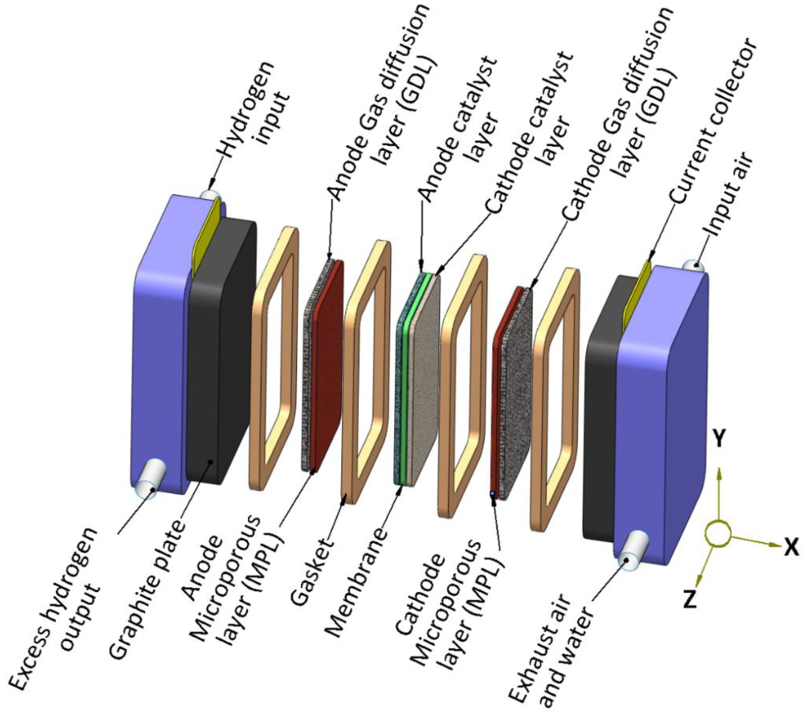


