Article

Experimental Investigation on Latent Thermal Energy Storages (LTESs) Based on Pure and Copper-Foam-Loaded PCMs

1
Department of Industrial Engineering, Alma Mater Studiorum Università di Bologna, Viale Risorgimento, 2, 40136 Bologna, Italy
2
CIRI-EC, Alma Mater Studiorum Università di Bologna, Via del Lazzaretto, 15, 40131 Bologna, Italy
*
Author to whom correspondence should be addressed.
Energies 2022, 15(13), 4894; https://doi.org/10.3390/en15134894
Submission received: 18 May 2022 / Revised: 20 June 2022 / Accepted: 28 June 2022 / Published: 4 July 2022
(This article belongs to the Topic Thermal Energy Transfer and Storage)

Abstract

:
In this work, a commercial paraffin PCM (RT35) characterized by a change range of the solid-liquid phase transition temperature T s l = 29 36 °C and the low thermal conductivity λ SL = 0.2 W/m K is experimentally tested by submitting it to thermal charging/discharging cycles. The paraffin is contained in a case with a rectangular base and heated from the top due to electrical resistance. The aim of this research is to show the benefits that a 95% porous copper metal foam (pore density P D = 20 P P I ) can bring to a PCM-based thermal storage system by simply loading it, due to the consequent increase in the effective thermal conductivity of the medium ( λ LOAD = 7.03 W/m K). The experimental results highlight the positive effects of the copper foam presence, such as the heat conduction improvement throughout the system, and a significant reduction in time for the complete melting of the PCM. In addition, the experimental data highlight that in the copper-foam-loaded PCM the maximum temperature reached during the heating process is lower than 20 K with respect to the test with pure PCM, imposing the same heat flux on the top ( P = 3.5 W/m2).

Graphical Abstract

1. Introduction

Renewable energy sources are usually non-programmable sources which need storage systems to balance energy demand with energy production. For thermal applications, if the heat generation is obtained using discontinuous energy sources such as solar or wind energy [1], the introduction of thermal energy storage systems (TESSs) is mandatory. Among the TESSs, the PCM-based ones are acquiring more and more importance due to the high latent heat storage capability of these materials which results in a significant storage volume reduction for a fixed quantity of energy stored [2]. Many papers have been devoted to the characterization of latent thermal energy storage systems (LTESSs) and nowadays PCM LTESSs find applications in several fields: civil [1,3], textile [4,5], food transport [6,7], agriculture [8], air conditioning [9], additive manufacturing (AM) for heat exchangers (HXs) [10], electronics [11,12,13], solar systems [14,15], and automotive [16,17,18,19]. Nazir et al. [20] propose a deep overview about several kinds of PCMs (different for their chemistry, phase change mechanisms, and melting points), focusing on their exploitation in several applications. For instance, they analyse PCM thermal storage capability in concentrating solar power (CSP) and battery thermal management (BTM) systems; they discuss PCM use in the civil field (photovoltaic panels coupled with a TESS for the thermal management of building envelopes) and highlight the benefits coming from the adoption of a PCM-based TES with respect to ordinary water storage (solar water heater). Concerning the automotive sector, electric vehicle (EV) market growth has given a boost to the research in the BTM direction. As a BTMS must prevent the battery pack (BP) from reaching temperatures outside the optimal working range (15–40 °C for Li-ion cells [21]), preserving its performance, safety, and state of health (SOH), PCMs are increasingly studied in this field, too. There are several reasons for a Li-ion battery (LIB) fault, such as thermal, mechanical, or electrical abuses [22], and the strategies to reduce potential accidents can be grouped into active and passive safety methods. An active strategy mainly relies on heat transfer increase to remove excess heat (forced-air or liquid BTMSs); a passive method works on exploiting TESSs, without an external energy supply, and modifying the physics of the materials involved (PCMs thermal management). The thermal storage capability of the PCMs can be efficiently exploited both to cool and to warm the batteries. Hu et al. [23] put in evidence the great advantage of using PCMs to warm a BP: the process goes on due to the thermal energy accumulated in the PCM, not consuming the BP energy. Several studies deal with the cooling effectiveness of PCMs if used together with the more ordinary BTMSs: Lin et al. [24] present several kinds of multi-physical BTMSs, that is, hybrid cooling systems such as forced-air, liquid, and heat-pipe (HP) BTMSs coupled with PCM-based systems, with the aim of ensuring battery cooling also after the PCM melting temperature is reached. In particular, HPs are often coupled with PCMs [25], as the low thermal conductivity of these materials is balanced by HPs’ great heat transfer performance. Other hybrid cooling systems concern dynamic BTMSs [26] with an adjustable cooling/heating capability to face the needs of the real BPs subjected to power peaks: an example is given by HP BTMSs with flexible PCMs [27]. Considering the phase change process, it is possible to classify the PCMs into solid-liquid, liquid-gas, and solid-gas materials: the first of these categories is the one which shows the smallest volume variation and highest stability [26] and comprehends organic, inorganic, and eutectic PCMs. Among the organic PCMs, the paraffin-based ones are very popular due to their small temperature drop during heat recovery, their low vapour pressure, and, in addition, their high chemical inertia, stability, and non-toxicity [28]. Conversely, a common negative property of many PCMs is their low thermal conductivity ( λ < 1 W/m K), which represents one of the biggest challenges in this field of research. As a matter of fact, low PCM thermal conductivity limits the potential of these materials, leading to low heat storage/release rates and a low utilization efficiency of the stored energy [29]. Different methods have been proposed to increase PCM thermal conductivity: the addition of fins [30,31,32], nanoparticles [33,34,35,36], both fins and nanoparticles together [37], graphite [38], carbon fibers [39], metal wools [40], 3D metallic periodic structures [41,42], and high-porosity metal foams [8,28,29,43,44,45,46,47,48]. This last solution has proven to be very effective due to the high thermal conductivity of the metal foams [49], the significant surface-area-to-volume ratio, the highly interconnected structure, and the natural fluid mixing effect [29].
Righetti et al. [41,42] study how to enhance the heat conductivity of paraffin PCMs with different phase change temperatures, using various 3D metallic periodic structures immersed in them and supplying different heat fluxes to the system. They find that the 3D structure greatly improves the heat transfer performance, significantly reducing the charging/discharging time. About 3D metallic non-periodic structures, Alhusseny et al. [44] investigate the effects of a copper foam inside LTESS staggered bundled tubes, already filled with pure paraffin PCM and around which water flow works as heating/cooling fluid: they obtain good results in terms of PCM charging/discharging rate (accelerated by more than 50% with respect to the corresponding system with pure PCM) and efficiency. Esapour et al. [28] enrich this field of research in studying a multi-tube heat exchanger (MTHX), analysing the effects of the metal foam porosity, the number of tubes, and their arrangement on the thermal characteristics of the LTES unit. Results show that a greater number of inner tubes has more influence on phase change rates using metal-foam-loaded PCMs with respect to pure PCMs and, in agreement with Righetti et al. [50] and Rehman et al. [47], the charging/discharging time decreases with the foam porosity. On the contrary, the arrangement of the inner tubes has no effect on the melting rate of the composite PCMs. Playing with the porosity parameter to achieve a more uniform temperature in the whole system, Mahdi et al. [46] suggest a multiple-segment metal foam characterized by a cascade porosity in the heat flow direction, put in a shell-and-tube HX storage containment. Dinesh et al. [51] focus their attention on metal foam pore size, demonstrating that, even for the same porosity, the pore size distribution strongly affects the PCM melting rate, with smaller pores resulting in faster melting and higher heat transfer rates. Ghahremannezhad et al. [45] analyse the effects of non-homogeneous porous metal foams (structures presenting positive and negative porous gradients in several spatial directions) on PCM melting behaviour. Their simulations put in evidence that the heat transfer is remarkably influenced by the porous characteristics of the metal foams and there are also changes considering the heat source location due to the gravity effect. A deep numerical and experimental work by Marri et al. [52] proposes a dissertation about PCM thermal performances if loaded with metal foams which present different values of porosity (uniform and non-uniform) and pore density (PD). Their results highlight that, with certain boundary conditions, the time to reach the set-point temperature can be significantly reduced, loading the PCM with foams having a non-uniform variation in porosity and a constant PD or a non-uniform variation in PD and a constant porosity. With respect to the reference foam with uniform porosity and PD, the performance improvement can range from 28% to 45%. The research by Zhu et al. [53] deals with the relationship between the proportion of a high-porous copper metal foam and the heat transfer process in a copper-foam-loaded PCM system. They find that the more the copper foam proportion increases, the higher the PCM thermal uniformity becomes; the natural convection motions dramatically decrease, making conduction the major heat transfer process for PCM melting; the effective heat transfer coefficient of the system first decreases and then, over a certain percentage value of copper foam, it increases, with an opposite trend with respect to PCM melting time. Finally, the researchers put in evidence how the heat storage capability of the loaded PCM first increases and then decreases with the increase in the copper foam percentage.
The analysis of the open literature puts in evidence that many numerical studies have been published on this topic but a lack of experimental data is still observed. For this reason, this work arises from the necessity to enrich the experimental tests, aiming to demonstrate the impact of metal foams in enhancing PCM effective thermal conductivity and providing solid bases for analytical studies validation [54,55]. The attention is focused on a commercial paraffin PCM (RT35): the aim is to quantify the effect of the metal foam on the charging time interval and on the maximum temperature needed to charge the PCM under a fixed thermal power provided with a heating plate placed on the top of the system.

2. Materials and Methods

A series of experimental tests were conducted using a polymeric case filled first with pure PCM and then with copper-foam-loaded PCM. The selected PCM was a commercial paraffin (RT35, Rubitherm) fully compatible with both plastic and metallic containers, highly stable, with a low toxicity and flammability degree. The choice of this kind of PCM was done with an eye to future research, the purpose of which is investigating a novel PCM-based BTMS: as the typical LIB operating temperature ranges from 15 °C to 40 °C [21], a PCM in this thermal interval is necessary and requires a previous characterization campaign. Regarding the system composed of the RT35 PCM and the selected copper metal foam ( ϕ = 95 % , P D = 20 P P I ), Naldi et al. [55] numerically investigate its effective thermal conductivity, finding that the value of the loaded system conductivity λ LOAD = 7.03 W/m K is in agreement with the experimental outcomes. This value is obtained using the accurate correlation by Bhattacharya et al. [49] which employs a weighted mean between the values of parallel and series conduction (when the PCM and metal foam layers alternate in the same direction of the heat flow or perpendicular to it, respectively) where the weight is experimentally determined. The main characteristics of RT35 and the copper metal foam used in these tests are summarized in Table 1.
A case (Figure 1a,c) was built with 5 mm thick polycarbonate (softening temperature T soft 115 °C) sheets and used as a PCM container whose final volume was V case = 1.08 × 10 6 mm3. In Figure 1a, all the dimensions of the case are quoted. Two different setups were used during the experimental tests. In the first setup (see Figure 1a), 12 T-type thermocouples were placed inside the case at two fixed heights: 6 TCs were fixed at a distance of 5 mm from the bottom of the case and 6 TCs were placed at a distance of 45 mm from the bottom of the case. For each of the two planes, the TCs were placed at fixed x- and y-quotes so that these values did not change at different heights and the pitch between the TCs lying on the same direction was constant. Considering the x direction, the TCs were fixed every 33.75 mm, at x 1 = 33.75 mm, x 2 = 67.50 mm, and x 3 = 101.25 mm. Along the y direction, the TCs were fixed every 26.60 mm, at y 1 = 26.60 mm and y 2 = 53.20 mm. Figure 1b shows a stage of the setup realization, in particular the welding work to fix the TCs on the iron wires: the TCs’ positions are not those of the final experimental rig, but the figure is useful for giving a more realistic idea of the experimental setup with respect to the scheme.
The case was filled with liquid PCM so that, once the paraffin material solidified, it reached the z-quote of 70 mm: considering the volume expansion of the RT35 PCM (Table 1), the polycarbonate container was filled with PCM volume V PCM = 8.47 × 10 5 mm3 (the related mass was m PCM = 0.652 kg) until reaching a a z-quote around 78.4 mm. In the second setup (see Figure 1c,d) the same polycarbonate case was used but with a different TC arrangement. As a matter of fact, 7 T-type TCs were inserted into the case: 2 TCs were placed below an electric resistance, in contact with its bottom surface, and 5 TCs were fixed along the central axis of the case, at different heights from the case bottom. More in detail: TCH1 and TCH2 were placed at 67 mm from the case bottom, TC1 was placed at 55 mm, TC2 at 42 mm, TC3 at 29 mm, TC4 at 16 mm, and TC5 at 3 mm. As TC1 was the highest, when it recorded a temperature value comprehended into the PCM melting temperature range, the whole PCM volume under that TC was considered as involved in the melting process (for 29 °C < T < 36 °C) or completely melted (for T 36 °C). One additional TC was used to record the temperature of the room ( T AIR ) during the experimental tests. The choice to fix the electric resistance (and so TCH1 and TCH2) at 67 mm from the case bottom ensured that, filling the container with the same liquid V PCM used in the first configuration, the heat generator was completely immersed in the paraffin.
The first setup was used to check if the heat transfer could be considered as mono-dimensional within the case by measuring the temperature distribution on two horizontal planes. The second setup was exploited to monitor the temperature trend at 5 different distances from the resistance (heater) during the charging/discharging phase with the aim to quantify the heat transfer rate along the vertical direction in the PCM core, investigating PCM behaviour with and without metal foams. In this regard, it is necessary to specify that, once the metal foam was immersed in the PCM, the TCs fixed along the iron wires were not in contact with the foam and kept monitoring the paraffin temperature: as it is possible to see in Figure 1d, a thin gap among the two main blocks of metal foam is necessary to leave space for the wires. The whole experimental setup is shown in Figure 2: a power supplier was connected to the heater in order to impose the heat flux generated by the Joule effect and the values of voltage and current were monitored due to an ammeter and a voltmeter. These data are shown in Table 2 together with the full scales ( F S ) considered and the full scale uncertainties ( % F S ) related to the instruments.
With these values of voltage and current, the resulting power supplied was P = V · i = 3.5 W/m2 and its related uncertainty value was U ( P ) = U 2 ( i ) + U 2 ( V ) = 11.77 % . The temperature values were acquired due to a series of NI-9213 thermocouple modules. The typical value of uncertainty of the T-type thermocouples was estimated to be U ( T ) = 0.4 0.7 K by means of a series of comparison with a reference RTD sensor. To obtain the complete melting of the whole PCM volume, the case was enclosed in a polystyrene box (Figure 3) with 100 mm thick walls: the aim was to minimize heat losses. Further, the thin air cavities between the polystyrene walls and the polycarbonate case were filled with EUROBATEX® [56], a dense insulating foam which helps in lowering the losses, as well as the inner surface of the polystyrene top.

3. Results and Discussion

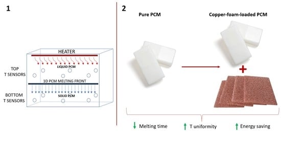
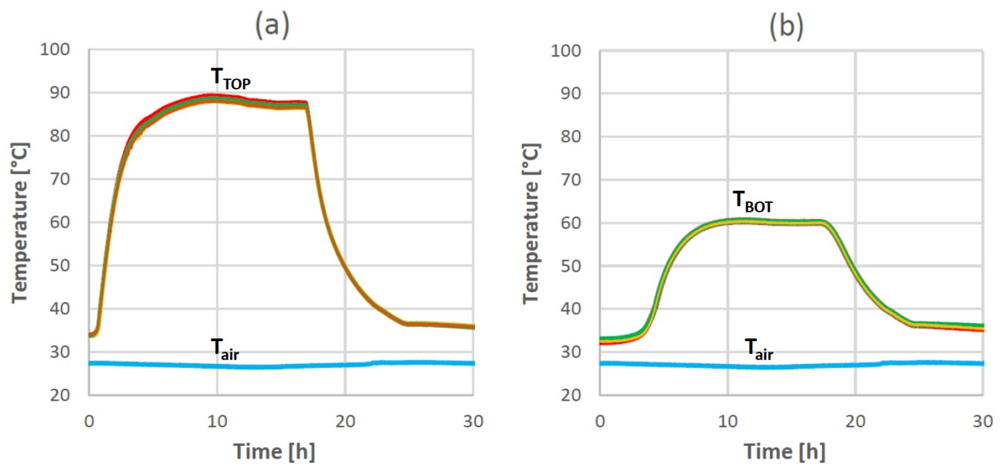
3.1. Temperature Homogeneity along the Horizontal Direction

The first setup described in the previous section (see Figure 1a) was used in order to check if the heat transfer within the case could be considered as mono-dimensional (1D). The PCM was heated from the top of the case to ensure that the heat was transferred within the PCM only by pure conduction. Due to the symmetry of the geometry, it was expected that the temperature was homogeneous on the horizontal planes (x,y), which means that the heat flux was only transmitted along the z-axis of the system, perpendicularly to the (x,y) planes. As it is possible to see in Figure 4, the temperature trends recorded by all six top-plane TCs, as well as by the other six bottom-plane ones, were very similar during the whole charging/discharging cycle. In addition, in Figure 4, the room temperature Tair is reported during the complete charging/discharging cycle. It is evident that Tair was almost constant during the cycle, which lasted 35 h with an average value of T air , med = 27.2 °C: this is the reason why the initial temperature of the PCM in the case was very close to the phase change interval of RT35.
For a heat flux P = 3.5 W/m2 applied on the top for 18.2 h (charging phase), the maximum temperature recorded on the top plane was T TOP 90 °C and the maximum temperature recorded on the bottom plane was T BOT 60 °C. The discharging phase, during which the PCM volume was cooled down to the initial temperature value (33.3 °C), lasted about 34.8 h. It is evident how, independently from the position of the TCs on the same horizontal plane (top or bottom), all the temperature trends recorded by TCs in Figure 4a,b overlapped. The maximum temperature difference recorded during the whole charging phase by the thermocouples on the same plane was Δ T TOP = 0.4 K for the top plane and Δ T BOT = 0.5 K for the bottom plane, within the uncertainty range of the TCs. This result confirms how the temperature field can be considered as variable only along the vertical direction z, especially in the central region of the case. The time needed to reach a quasi steady-state temperature on the top plane, closer to the heater, was about 8 h. This time was longer for the bottom plane (far from the heater), where about 10 h were needed to obtain a stable temperature value. The discharging phase lasted about 6 h for both the top and the bottom planes.

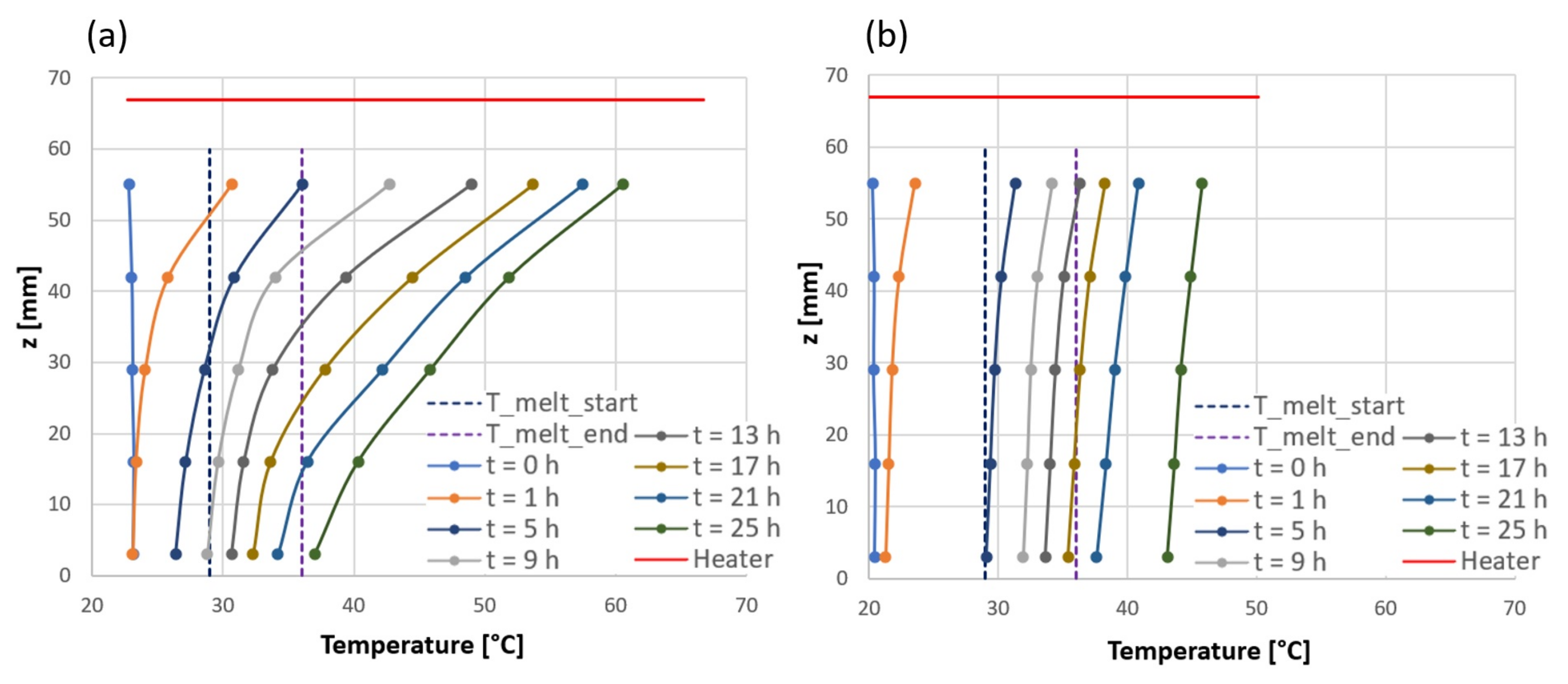
3.2. Comparison between Pure PCM and Copper-Foam-Loaded PCM

Once the temperature homogeneity along the x and y directions was verified, the experimental setup iwass changed to better monitor the evolution in time of the melting front from the top to the bottom of the case. Two series of tests were conducted: the first one was carried on filling the polycarbonate case with pure PCM, and for the second one the PCM was loaded with copper foam. The second setup described in Figure 1c was adopted here to analyse the temperature distribution within the case, along the vertical direction (z) at the center of the case, and to verify the effect of the metallic foam on the temperature distribution. The experimental tests were conducted with the electric heater on the top of the case, supplying power for 23.7 h (charging phase). The heat flux imposed on the top by Joule heating was P = 3.5 W/m2. In Figure 5a,b the evolution in time of the temperature within the case is shown for both pure PCM and copper-foam-loaded PCM. In addition, in these graphs the temperature of the lower surface of the electric heater (red curve) is shown: this temperature was obtained as the average of the temperatures measured by the two TCs placed below the heater (see Figure 1c). In Figure 5a, the trends of the temperature recorded in the presence of pure RT35 are reported. After 15 h, the temperature difference between the closer and the further thermocouple with respect to the heater (i.e., T C 1 and T C 5 ) was Δ T 1 5 , PURE = 20 K. This large temperature difference within the case highlights how strong the thermal resistance offered by the pure PCM was due to the low thermal conductivity typical of the paraffin. Starting from an initial temperature T 0 , PURE = 23 °C, the whole volume of pure PCM melted in 23.7 h, when the PCM temperature close to the heater (the average between T C H 1 and T C H 2 ) reached a value of 66 °C.
In the presence of the copper foam, the charging test was repeated and monitored due to the seven TCs described in Figure 1c, supplying to the heater the same power used for the test with pure PCM. This was guaranteed by imposing the same electrical voltage and current at the heater. In Figure 5b, the trends of temperature recorded in the presence of copper foam are shown. After 15 h, the temperature difference between T C 1 and T C 5 was Δ T 1 5 , FOAM = 3 K: this means that loading the PCM with the copper foam allows for reducing the thermal resistance by about one order of magnitude. This result confirms the beneficial effect of the copper metal foam if the goal of the designer is to reduce the melting time and accelerate the heat transfer rate. The presence of a high-porosity copper metal foam significantly increases the effective thermal conductivity of the system and reduces the temperature gradient along the vertical direction z. The graphs in Figure 6a,b show the evolution in time of the vertical temperature profile recorded by the five TCs placed along the central axis of the case during the charging phase with pure (Figure 6a) and metal-foam-loaded (Figure 6b) PCMs. In addition, in this case, the temperature of the lower surface of the electric heater (red curve) is shown. Every dot of the curves plotted in these graphs represents the temperature recorded at the related height, the same where the TC is fixed. Two dashed vertical lines indicate the temperature melting range for the RT35 PCM so that, if a curve dot lies in that spatial interval, it means that the PCM volume under the z-quote correspondent to that dot is melting (dot between the two dashed lines) or it is completely melted (dot coincident with the right dashed line or on the right area with respect to that line). Further, considering the dot z-quote and knowing that it is at most possible to investigate the temperature of the PCM layer at the same height of TC1 (there are no other TCs above it, apart from TCH1 and TCH2 which measure the heater temperature), the PCM volume effectively under thermal control can be considered as the total volume. In this way, it is possible to estimate the PCM melted volume: for instance, if the dot corresponding to TC3 falls between the dashed lines, this means that 50% of the PCM is involved in the melting process.
As it is possible to see in Figure 6a, with pure PCM, the melting process began just 1 h after the charging process started, close to the heater (at 55 mm from the bottom); on the contrary, in the presence of the copper foam (Figure 6b), the melting range was not reached, yet. As a matter of fact, in the presence of the copper foam, when the charging process started, the heat was transferred faster by conduction from the top to the bottom layers and a larger thickness of PCM started to be charged. In the presence of pure PCM (Figure 6a), the temperature difference between the closer and the further TCs to the heater ( Δ T 1 5 , PURE ) increased strongly in time: passing through the paraffin material, the heat was slowed down due to the low thermal conductivity of the PCM. The last thermocouple reached the melting temperature after 9 h. In the presence of copper-foam-loaded PCM (Figure 6b), the five TCs worked with very similar temperature values during the whole charging phase, with a maximum difference between T C 1 and T C 5 equal to Δ T 1 5 , FOAM = 2.7 K after 25 h. Although the test with copper-foam-loaded PCM started with an initial temperature within the case equal to T 0 , FOAM = 21 °C (2 °C lower than T 0 , PURE = 23 °C, as this temperature depends on the internal conditions of the lab), the final results were marginally influenced (the acquired data demonstrate that the loaded PCM took 42 min = 0.7 h to reach 23 °C). The whole PCM volume completely melted in 16 h (7 h earlier than in the presence of pure PCM, considering the different initial temperatures between the tests), when T C 5 reached 35 °C.
Figure 5b and Figure 6b demonstrate how, in the presence of copper foam, the vertical temperature distribution within the case is always more uniform than in the presence of pure PCM during the whole charging process. After t = 5 h, with the copper foam, the entire volume of the PCM was in the melting range; on the contrary, with the pure PCM, only 59.4% of the case volume was in that range. From t = 9 h to t = 13 h, the copper-foam-loaded PCM was completely involved in the melting process and after t = 13 h about 7.8% of the PCM volume was already in a super-heated liquid state (a liquid state with a temperature higher than the melting one [57]). On the contrary, in the presence of pure PCM, the more time that passes, the higher the thermal difference between the top and bottom layers becomes: after t = 9 h, the solid phase was still present on the case bottom; after t = 13 h, there was no more solid PCM, but the thermal distribution indicates how the PCM layers close to the heater were in a liquid state, while the bottom layers were still involved in the melting process. As clearly evidenced by Figure 5a,b, complete melting was reached in 23.7 h with the pure PCM and in 16 h with the copper-foam-loaded PCM. This result confirms the positive effect of the metal foam on the acceleration of the melting phase. In addition, comparing Figure 6a,b, it is possible to see that after t = 25 h the temperature difference between the extreme TCs ( T C 1 and T C 5 ) was Δ T 1 5 , PURE 23.6 K in the presence of pure PCM but only Δ T 1 5 , FOAM 2.7 K in the presence of the copper foam: this highlights the strong increase in the temperature uniformity along the vertical direction obtained with the introduction of the metal foam. Another important point is the difference between the heater temperature with and without the copper foam: after t = 25 h (see Figure 5a,b), the heater reached T H , PURE = 67 °C with the pure PCM and T H , FOAM = 50.1 °C in the presence of the copper foam. In order to melt the whole PCM volume, the heater has to reach a temperature T H , PURE = 66 °C with the pure PCM and T H , FOAM = 44 °C in the presence of the copper foam. The higher heater temperature in the presence of pure PCM is a clear consequence of the low conductivity of the paraffin which acts as a cap towards the heat transfer. This point is very important because it demonstrates that, with enhanced thermal conductivity, the PCM can be completely (and more rapidly) melted using lower temperatures, which makes the charging process faster and the energy saving higher.

4. Conclusions

An experimental campaign has been conducted with the aim to investigate how much the presence of a copper metal foam with high porosity (95%) and a pore density of P D = 20 P P I influences the thermal performance of a commercial paraffin PCM (RT35) during a solid-liquid phase change process. The presence of the metal foam guarantees an enhancement of the heat conduction within the medium, compensating for the low thermal conductivity of the pure RT35 ( λ SL = 0.2 W/m K for both liquid and solid phases). A polycarbonate case has been equipped with a series of T-type thermocouples. The case has been filled first with pure RT35 PCM and then with copper-foam-loaded PCM. An electric heater has been placed on the top of the case with the aim of thermally charging the system. The position of the heater on the top of the case inhibits the convection, making pure conduction the main heat transfer process. First, it has been demonstrated that during the charging as well as the discharging processes, the melting front is kept planar and horizontal due to a uniform temperature field along both the directions x and y. Comparing the pure and the loaded PCM temperature evolution over time and along the central axis of the case, a faster complete melting can be reached with a metal-foam-loaded PCM with respect to a pure one (16 h instead of 23.7 h). Taking into account the aforementioned different initial temperatures regarding the pure PCM and the loaded PCM and the time during which the loaded PCM reaches the same temperature of the pure PCM, results show a 29.54% melting time reduction. The copper foam is responsible for a more uniform temperature along the vertical direction z, which testifies to a reduced thermal resistance of the metal-foam-loaded PCM layers. A strong reduction in the maximum temperature needed to melt the whole PCM volume is recorded with the metal foam (44 °C instead of 66 °C), keeping the imposed heat flux at the top of the case constant (P = 3.5 W/m2). The experimental results presented in this paper highlight that, using metal foams to load PCM-based LTESSs, it is possible to reach a more uniform heating of the PCM volume as well as a faster charging/discharging process with a lower working temperature and the consequent possibility to obtain significant energy saving for thermal storage management. Last but not least, the experimental results reported in this work can be used as a benchmark for the numerical models dedicated to the analysis of the loaded PCMs’ thermal behaviour. The absence of convection heat transfer (linked to the position of the heater) makes the case easy to be numerically modelled and, for this reason, useful for a critical validation regarding the correlations proposed to calculate the effective properties of the loaded PCMs.

Author Contributions

Conceptualization, M.F., D.R. and G.L.M.; methodology, M.F., D.R. and G.L.M.; software, M.F. and D.R.; investigation, M.F.; resources, M.F., D.R., M.D., C.N. and G.L.M.; data curation, M.F.; writing, M.F.; editing, M.F.; review, M.F., M.D., C.N. and G.L.M.; supervision, G.L.M.; funding acquisition, B.P. and G.L.M. All authors have read and agreed to the published version of the manuscript.

Funding

This paper is supported by the European Union’s Horizon 2020 research and innovation programme under grant agreement n°818012, project Hybrid-BioVGE (Hybrid Variable Geometry Ejector Cooling and Heating System for Buildings Driven by Solar and Biomass Heat).

Acknowledgments

The authors would like to thank Eng. Alessandro Bianchini for his precious support during the experiments.

Conflicts of Interest

The authors declare no conflict of interest.

Abbreviations

The following abbreviations are used in this manuscript:
AMAdditive manufacturing
BPBattery pack
BTMBattery thermal management
BTMSBattery thermal management system
CSPConcentrating solar power
EVElectric vehicle
HPHeat pipes
HXHeat exchanger
LIBLithium-ion battery
LTESLatent thermal energy storage
LTESSLatent thermal energy storage system
MTHXMulti-tube heat exchanger
PCMPhase change material
PDPore density
PPIPores per inches
RTDResistance temperature detector
SOHState of health
TCThermocouple
TESSThermal energy storage system

References

  1. Zeinelabdein, R.; Omer, S.; Gan, G. Critical review of latent heat storage systems for free cooling in buildingserformance studies of refrigerated van having. Renew. Sustain. Energy Rev. 2018, 82, 2843–2868. [Google Scholar] [CrossRef]
  2. Fadl, M.; Eames, P.C. An experimental investigation of the heat transfer and energy storage characteristics of a compact latent heat thermal energy storage system for domestic hot water applications. Energy 2019, 188, 116083. [Google Scholar] [CrossRef]
  3. Alkhazaleh, A.; Kandola, B. Thermal and Flammability Properties of Paraffin/Nanoclay Composite Phase Change Materials Incorporated in Building Materials for Thermal Energy Storage. Int. J. Energy Power Eng. 2017, 11, 696–701. [Google Scholar]
  4. Ahrari, M.; Khajavi, R.; Dolatabadi, M.K.; Toliyat, T.; Rashidi, A. A review on application of phase change materials in textiles finishing. Int. J. Mater. Metall. Eng. 2017, 11, 400–405. [Google Scholar]
  5. BM Information. BMW Motorrad Rider Equipment 2018; Technical Report; 2017. Available online: https://www.press.bmwgroup.com/global/article/detail/T0275552EN/bmw-motorrad-rider-equipment-2018?language=en (accessed on 17 May 2022).
  6. Sharma, M.K.; Buddhi, D. Performance studies of refrigerated van having PCM for generating off site refrigeration effect. J. Pure Appl. Sci. Technol. 2013, 3, 1–12. [Google Scholar]
  7. Oró, E.; Miró, L.; Farid, M.M.; Cabeza, L.F. Improving thermal performance of freezers using phase change materials. Int. J. Refrig. 2012, 35, 984–991. [Google Scholar] [CrossRef]
  8. Borhani, M.; Hosseini, M.J.; Pakrouh, R.; Ranjbar, A.A.; Nourian, A. Performance Enhancement of a Thermoelectric Harvester with a PCM/Metal Foam Composite. Renew. Energy 2021, 168, 1122–1140. [Google Scholar] [CrossRef]
  9. Li, S.F.; Liu, Z.h.; Wang, X.J. A comprehensive review on positive cold energy storage technologies and applications in air conditioning with phase change materials. Appl. Energy 2019, 255, 113667. [Google Scholar] [CrossRef]
  10. Kaur, I.; Singh, P. State-of-the-art in heat exchanger additive manufacturing. Int. J. Heat Mass Transf. 2021, 178, 121600. [Google Scholar] [CrossRef]
  11. Pakrouh, R.; Hosseini, M.J.; Ranjbar, A.A.; Bahrampoury, R. A numerical method for PCM-based pin fin heat sinks optimization. Energy Convers. Manag. 2015, 103, 542–552. [Google Scholar] [CrossRef]
  12. Ren, Q.; Guo, P.; Zhu, J. Thermal management of electronic devices using pin-fin based cascade microencapsulated PCM/expanded graphite composite. Int. J. Heat Mass Transf. 2020, 149, 119199. [Google Scholar] [CrossRef]
  13. Mills, A.; Al-Hallaj, S. Simulation of passive thermal management system for lithium-ion battery packs. J. Power Sources 2005, 141, 307–315. [Google Scholar] [CrossRef]
  14. Ananno, A.A.; Masud, M.H.; Dabnichki, P.; Ahmed, A. Design and numerical analysis of a hybrid geothermal PCM flat plate solar collector dryer for developing countries. Sol. Energy 2020, 196, 270–286. [Google Scholar] [CrossRef]
  15. Eisapour, M.; Eisapour, A.H.; Hosseini, M.J.; Sardari, P.T. Exergy and energy analysis of wavy tubes photovoltaic-thermal systems using microencapsulated PCM nano-slurry coolant fluid. Appl. Energy 2020, 266, 114849. [Google Scholar] [CrossRef]
  16. Jaguemont, J.; Omar, N.; Van den Bossche, P.; Mierlo, J. Phase-change materials (PCM) for automotive applications: A review. Appl. Therm. Eng. 2018, 132, 308–320. [Google Scholar] [CrossRef]
  17. Ianniciello, L.; Biwolé, P.H.; Achard, P. Electric vehicles batteries thermal management systems employing phase change materials. J. Power Sources 2018, 378, 383–403. [Google Scholar] [CrossRef]
  18. Al-Hallaj, S.; Selman, J.R. A novel thermal management system for electric vehicle batteries using phase-change material. J. Electrochem. Soc. 2000, 147, 3231. [Google Scholar] [CrossRef]
  19. Hémery, C.V.; Pra, F.; Robin, J.F.; Marty, P. Experimental performances of a battery thermal management system using a phase change material. J. Power Sources 2014, 270, 349–358. [Google Scholar] [CrossRef]
  20. Nazir, H.; Batool, M.; Osorio, F.J.B.; Isaza-Ruiz, M.; Xu, X.; Vignarooban, K.; Phelan, P.; Kannan, A.M. Recent developments in phase change materials for energy storage applications: A review. Int. J. Heat Mass Transf. 2019, 129, 491–523. [Google Scholar] [CrossRef]
  21. Wang, Q.; Jiang, B.; Li, B.; Yan, Y. A critical review of thermal management models and solutions of lithium-ion batteries for the development of pure electric vehicles. Renew. Sustain. Energy Rev. 2016, 64, 106–128. [Google Scholar] [CrossRef]
  22. Qiu, Y.; Jiang, F. A review on passive and active strategies of enhancing the safety of lithium-ion batteries. Int. J. Heat Mass Transf. 2022, 184, 122288. [Google Scholar] [CrossRef]
  23. Hu, X.; Zheng, Y.; Howey, D.A.; Perez, H.; Foley, A.; Pecht, M. Battery warm-up methodologies at subzero temperatures for automotive applications: Recent advances and perspectives. Prog. Energy Combust. Sci. 2020, 77, 100806. [Google Scholar] [CrossRef]
  24. Lin, J.; Liu, X.; Li, S.; Zhang, C.; Yang, S. A review on recent progress, challenges and perspective of battery thermal management system. Int. J. Heat Mass Transf. 2021, 167, 120834. [Google Scholar] [CrossRef]
  25. He, L.; Tang, X.; Luo, Q.; Liao, Y.; Luo, X.; Liu, J.; Ma, L.; Dong, D.; Gan, Y.; Li, Y. Structure optimization of a heat pipe-cooling battery thermal management system based on fuzzy grey relational analysis. Int. J. Heat Mass Transf. 2022, 182, 121924. [Google Scholar] [CrossRef]
  26. Yue, Q.; He, C.; Wu, M.; Zhao, T. Advances in thermal management systems for next-generation power batteries. Int. J. Heat Mass Transf. 2021, 181, 121853. [Google Scholar] [CrossRef]
  27. Wu, W.; Liu, J.; Liu, M.; Rao, Z.; Deng, H.; Wang, Q.; Qi, X.; Wang, S. An innovative battery thermal management with thermally induced flexible phase change material. Energy Convers. Manag. 2020, 221, 113145. [Google Scholar] [CrossRef]
  28. Esapour, M.; Hamzehnezhad, A.; Darzi, A.A.R.; Jourabian, M. Melting and solidification of PCM embedded in porous metal foam in horizontal multi-tube heat storage system. Energy Convers. Manag. 2018, 171, 398–410. [Google Scholar] [CrossRef]
  29. El Idi, M.M.; Karkri, M. Heating and cooling conditions effects on the kinetic of phase change of PCM embedded in metal foam. Case Stud. Therm. Eng. 2020, 21, 100716. [Google Scholar] [CrossRef]
  30. Biwole, P.H.; Groulx, D.; Souayfane, F.; Chiu, T. Influence of fin size and distribution on solid-liquid phase change in a rectangular enclosure. Int. J. Therm. Sci. 2018, 124, 433–446. [Google Scholar] [CrossRef]
  31. Al-Abidi, A.; Mat, S.; Sopian, K.B.; Sulaiman, M.Y.; Mohammad, A.T. Numerical study of PCM solidification in a triplex tube heat exchanger with internal and external fins. Int. J. Heat Mass Transf. 2013, 61, 684–695. [Google Scholar] [CrossRef]
  32. Ji, C.; Qin, Z.; Low, Z.; Dubey, S.; Choo, F.H.; Duan, F. Non-uniform heat transfer suppression to enhance PCM melting by angled fins. Appl. Therm. Eng. 2018, 129, 269–279. [Google Scholar] [CrossRef]
  33. Arıcı, M.; Tütüncü, E.; Kan, M.; Karabay, H. Melting of nanoparticle-enhanced paraffin wax in a rectangular enclosure with partially active walls. Int. J. Heat Mass Transf. 2017, 104, 7–17. [Google Scholar] [CrossRef]
  34. Colla, L.; Fedele, L.; Mancin, S.; Danza, L.; Manca, O. Nano-PCMs for enhanced energy storage and passive cooling applications. Appl. Therm. Eng. 2017, 110, 584–589. [Google Scholar] [CrossRef]
  35. Krishna, J.; Kishore, P.S.; Solomon, A.B. Heat pipe with nano enhanced-PCM for electronic cooling application. Exp. Therm. Fluid Sci. 2017, 81, 84–92. [Google Scholar] [CrossRef] [Green Version]
  36. Arasu, V.; Mujumdar, A.S. Numerical study on melting of paraffin wax with Al2O3 in a square enclosure. Int. Commun. Heat Mass Transf. 2012, 39, 8–16. [Google Scholar] [CrossRef]
  37. Darzi, A.A.R.; Jourabian, M.; Farhadi, M. Melting and solidification of PCM enhanced by radial conductive fins and nanoparticles in cylindrical annulus. Energy Convers. Manag. 2016, 118, 253–263. [Google Scholar] [CrossRef]
  38. Cabeza, L.F.; Mehling, H.; Hiebler, S.; Ziegler, F. Heat transfer enhancement in water when used as PCM in thermal energy storage. Appl. Therm. Eng. 2002, 22, 1141–1151. [Google Scholar] [CrossRef]
  39. Samimi, F.; Babapoor, A.; Azizi, M.; Karimi, G. Thermal management analysis of a Li-ion battery cell using phase change material loaded with carbon fibers. Energy 2016, 96, 355–371. [Google Scholar] [CrossRef]
  40. Fan, L.; Khodadadi, J.M. Thermal conductivity enhancement of phase change materials for thermal energy storage: A review. Renew. Sustain. Energy Rev. 2011, 15, 24–46. [Google Scholar] [CrossRef]
  41. Righetti, G.; Doretti, L.; Zilio, C.; Longo, G.A.; Mancin, S. Experimental investigation of phase change of medium/high temperature paraffin wax embedded in 3D periodic structure. Int. J. Thermofluids 2020, 5, 100035. [Google Scholar] [CrossRef]
  42. Righetti, G.; Savio, G.; Meneghello, R.; Doretti, L.; Mancin, S. Experimental study of phase change material (PCM) embedded in 3D periodic structures realized via additive manufacturing. Int. J. Therm. Sci. 2020, 153, 106376. [Google Scholar] [CrossRef]
  43. Rehman, T.-U.; Ali, H.; Janjua, M.; Sajjad, U.; Yan, W.M. A critical review on heat transfer augmentation of phase change materials embedded with porous materials/foams. Int. J. Heat Mass Transf. 2019, 135, 649–673. [Google Scholar] [CrossRef]
  44. Alhusseny, A.; Al-Zurfi, N.; Nasser, A.; Al-Fatlawi, A.; Aljanabi, M. Impact of using a PCM-metal foam composite on charging/discharging process of bundled-tube LHTES units. Int. J. Heat Mass Transf. 2020, 150, 119320. [Google Scholar] [CrossRef]
  45. Ghahremannezhad, A.; Xu, H.; Salimpour, M.R.; Wang, P.; Vafai, K. Thermal performance analysis of phase change materials (PCMs) embedded in gradient porous metal foams. Appl. Therm. Eng. 2020, 179, 115731. [Google Scholar] [CrossRef]
  46. Mahdi, J.M.; Nsofor, E.C. Multiple-segment metal foam application in the shell-and-tube PCM thermal energy storage system. J. Energy Storage 2018, 20, 529–541. [Google Scholar] [CrossRef]
  47. Rehman, T.-U.; Ali, H. Experimental study on the thermal behavior of RT-35HC paraffin within copper and Iron-Nickel open cell foams: Energy storage for thermal management of electronics. Int. J. Heat Mass Transf. 2020, 146, 118852. [Google Scholar] [CrossRef]
  48. Zhang, P.; Meng, Z.; Zhu, H.; Wang, Y.; Peng, S. Melting heat transfer characteristics of a composite phase change material fabricated by paraffin and metal foam. Appl. Energy 2017, 185, 1971–1983. [Google Scholar] [CrossRef] [Green Version]
  49. Bhattacharya, A.; Calmidi, V.V.; Mahajan, R.L. Thermophysical properties of high porosity metal foams. Int. J. Heat Mass Transf. 2002, 45, 1017–1031. [Google Scholar] [CrossRef]
  50. Righetti, G.; Lazzarin, R.; Noro, M.; Mancin, S. Phase change materials embedded in porous matrices for hybrid thermal energy storages: Experimental results and modeling. Int. J. Refrig. 2019, 106, 266–277. [Google Scholar] [CrossRef]
  51. Dinesh, B.V.S.; Bhattacharya, A. Comparison of energy absorption characteristics of PCM-metal foam systems with different pore size distributions. J. Energy Storage 2020, 28, 101190. [Google Scholar] [CrossRef]
  52. Marri, G.K.; Balaji, C. Experimental and numerical investigations on the effect of porosity and PPI gradients of metal foams on the thermal performance of a composite phase change material heat sink. Int. J. Heat Mass Transf. 2021, 164, 120454. [Google Scholar] [CrossRef]
  53. Zhu, M.; Wang, Z.; Zhang, H.; Sun, X.; Dou, B.; Wu, W.; Zhang, G.; Jiang, L. Experimental investigation of the comprehensive heat transfer performance of PCMs filled with CMF in a heat storage device. Int. J. Heat Mass Transf. 2022, 188, 122582. [Google Scholar] [CrossRef]
  54. Naldi, C.; Dongellini, M.; Salvi, F.; Silvestrini, M.; Falcone, M.; Morini, G.L. Numerical model calibration for composite-PCM LTES. In Proceedings of the PCM2021 13th IIR - Phase Change Materials and Slurries for Refrigeration and Air Conditioning Conference, Vicenza, Italy, 1–3 September 2021. [Google Scholar] [CrossRef]
  55. Naldi, C.; Dongellini, M.; Morini, G.L. The evaluation of the effective thermal conductivity of metal-foam loaded phase change materials. J. Energy Storage 2022, 51, 104450. [Google Scholar] [CrossRef]
  56. Eurobatex®. Eurobatex® Data Sheet. Available online: https://www.unionfoam.it/doc/up/338698001630987597.pdf (accessed on 17 May 2022).
  57. Izgi, B.; Arslan, M. Numerical analysis of solidification of PCM in a closed vertical cylinder for thermal energy storage applications. Heat Mass Transf. 2020, 56, 2909–2922. [Google Scholar] [CrossRef]
Figure 1. (a) Scheme of the polycarbonate case used to test the temperature homogeneity along the z-axis; (b) welding work in progress to fix the 6 bottom TCs of the experimental rig; (c) scheme of the polycarbonate case used to monitor the melting front progress; (d) experimental rig with 5 TCs placed along the z-axis.
Energies 15 04894 g001
Figure 2. Experimental setup composed of the polycarbonate case (A), the heater on the top of the case (B), the polystyrene box which insulates the case (C), the NI-9213 TCs module (D), the power supply (E), and the computer (F).
Energies 15 04894 g002
Figure 3. (a) Assembling of the polystyrene box, top view; (b) detail of the air cavities filled with EUROBATEX® [56]; (c) inner surface of the polystyrene top wrapped with a EUROBATEX® [56] layer; (d) final assembly of the insulation box.
Energies 15 04894 g003
Figure 4. Temperature trends recorded by the 6 TCs on the top plane (a) and by the 6 TCs on the bottom plane (b).
Energies 15 04894 g004
Figure 5. Temperature trends recorded by the TCs during the tests with pure PCM (a) and with copper-foam-loaded PCM (b).
Energies 15 04894 g005
Figure 6. Constant-time curves as functions of height (z) and temperature during the tests with pure PCM (a) and with copper-foam-loaded PCM (b).
Energies 15 04894 g006
Table 1. RT35 PCM and copper metal foam properties provided by the manufacturers.
PCMSymbolUnitValue
Phase change temperature range from solid to liquid T s l [°C]29–36
Phase change temperature range from liquid to solid T l s [°C]36–31
Heat storage capacityH[kJ/kg]160
Specific heat capacity c p [kJ/kg K]2
Density of the solid phase ρ s [kg/L]0.86
Density of the liquid phase ρ l [kg/L]0.77
Heat conductivity for both solid and liquid phases λ SL [W/m K]0.2
Volume expansion V exp [%]12
Flash temperature T flash [°C]167
Maximum working temperature T w , max [°C]65
Copper foam
Heat conductivity λ cop [W/m K]385
Porosity ϕ [%]95
Pore density P D P P I 20
Polycarbonate
Density ρ pol [g/cm3]1.2
Softening temperature T soft [°C]115
Table 2. Instruments used to monitor the electrical current and voltage values and related full-scale ( F S ) and full-scale uncertainty ( U ( % F S ) ) values.
InstrumentQuantityUnitMeasured ValueFSU(%FS)
Ammeteri[A]0.212
VoltmeterV[V]17.5303.6
Publisher’s Note: MDPI stays neutral with regard to jurisdictional claims in published maps and institutional affiliations.

