Article

A Visualized Experimental Study on the Influence of Reflux Hole on the Double Blades Self-Priming Pump Performance

1
Zhejiang Engineering Research Center for Advanced Hydraulic Equipment, School of Mechanical and Automotive Engineering, Zhejiang University of Water Resources and Electric Power, Hangzhou 310018, China
2
College of Metrology & Measurement Engineering, China Jiliang University, Hangzhou 310018, China
3
Shimge Pump Industry (Hangzhou) Co., Ltd., Hangzhou 310018, China
*
Author to whom correspondence should be addressed.
Energies 2022, 15(13), 4617; https://doi.org/10.3390/en15134617
Submission received: 15 May 2022 / Revised: 18 June 2022 / Accepted: 21 June 2022 / Published: 24 June 2022
(This article belongs to the Special Issue Key Technologies and Challenges of Hydraulic Machinery and Systems)

Abstract

:
The self-priming pump is a kind of centrifugal pump product with self-priming function, and the structural parameters of its reflux hole determine the performance. In order to reveal the mechanism of the self-priming process, we summarized the influence of structure parameters of the reflux hole on the performance of the self-priming pump. In this study, the transparent experimental pump was designed and manufactured, and a visual test bench was built. The gas–liquid two-phase flow pattern during the self-priming process with different reflux hole structure parameters was captured by high-speed camera. Results showed that: (1) the reflux hole of the self-priming pump affected the self-priming performance of the pump by affecting the backflow rate of the gas and liquid phases during the self-priming process. (2) Due to the uneven distribution of liquid velocity in the pump, the position of reflux hole had an obvious impact on the duration of self-priming middle stage, and the shortest duration was 13 s when φ = +15° and the longest duration was 45 s when φ = −30°. (3) The diameter of reflux hole had a very significant impact on the duration of the self-priming middle stage, and the shortest duration was 17 s when d = 10 mm and the longest duration was 94 s when d = 0 mm.

1. Introduction

The self-priming pump is a centrifugal pump with a special exhaust structure, which can discharge the gas in the pump through the movement of the impeller, thereby realizing the suction of the liquid into pump. It is widely used in municipal, agricultural, petrochemical, and energy fields [1,2,3,4,5]. The exhaust process of the self-priming pump is a complex gas–liquid two-phase mixing-separation process where the gas exhaust rate determines the self-priming performance of the self-priming pump; based on previous studies, the structure parameters of the reflux hole are the main influence factors [6]. However, because of the transient gas–liquid two-phase flow with strong swirl during the self-priming process, the mechanism of the self-priming process was not revealed yet, and the influence mechanism of reflux hole structure parameters on self-priming performance is even more difficult to reveal, which seriously restricts the performance improve of self-priming pumps.
With the advancement of gas–liquid two-phase flow observation technology, high-speed camera has been widely used in the study of gas–liquid two-phase flow in centrifugal pumps and has achieved significant results [7,8,9]. Barrios et al. [10,11] studied the flow patterns and bubble behavior inside the ESP and predicted the operational conditions which cause surging by visual experimental and theoretical analysis. Monte Verde [12] and Zhang et al. [13] studied the dynamic multiphase flow behavior inside the impeller under different gas volume fractions with high-speed camera. The correlation between the change of centrifugal pump performance and the flow state of the gas phase in the impeller was revealed. With the gas volume fraction rising, there were four different flow patterns in the pump: bubble flow, agglomerated bubble flow, gas pocket flow, and segregated flow. The above research indicated that the visualization experiment is of great significance to explore the gas–liquid two-phase flow pattern in the pump.
In the research of self-priming pump, numerical simulation is still the main method [14,15,16]; the inner flow of vertical [17], horizontal [18], vortex [19], and jetting [20] self-priming pumps has been studied by numerical simulation. However, due to the serious mixing of the gas–liquid two-phase in the pump, it is difficult to accurately capture the gas–liquid two phase interface in numerical simulation. Some researchers have used high-speed cameras to study the self-priming process and the gas–liquid two-phase mixing process of the self-priming pump [21,22,23] and summarized the gas–liquid two-phase circulation law in the pump [24]. However, the researchers are focused on the gas–liquid separation chamber and the volute diffusion section, and less attention is paid to the flow pattern at the reflux hole. At the same time, the influence mechanism of the reflux hole structure parameters on the performance of the self-priming pump has not been revealed. In this study, a visual test bench was built, the gas–liquid two-phase flow pattern in the pump during self-priming process was fully captured by high-speed cameras, and the gas–liquid circulation law under different reflux hole positions and diameters was studied to reveal the influence mechanism of the reflux hole structure parameters on the self-priming performance. This study provides experimental support for self-priming pump research.

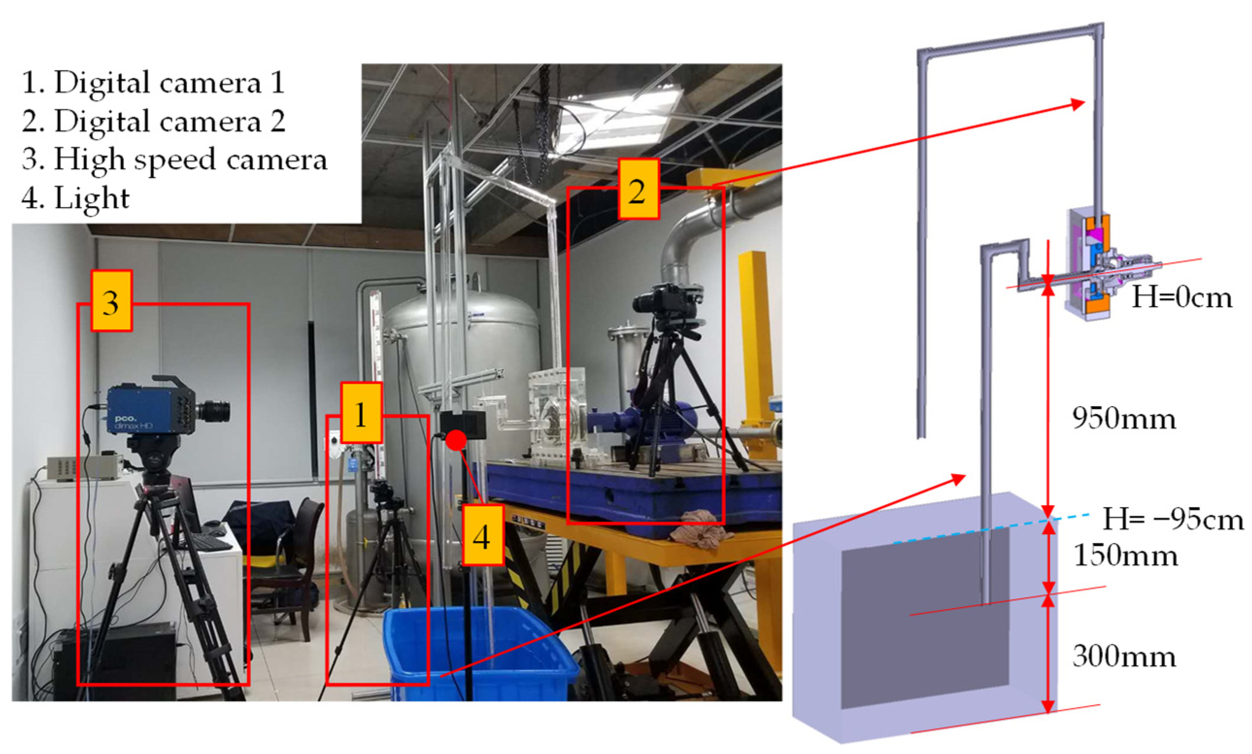
2. Experimental Facility and Method

The visual test bench is mainly composed of two parts: the experimental pump and the image acquisition part. In order to deeply reveal the influence mechanism of the reflux hole structure parameters on the performance of the self-priming pump, and to capture the complete motion state of the two-phase flow in the pump, the zw50-20-20 self-priming pump was used as a prototype. In the design of the transparent experimental pump, the structural parameters of impeller and volute were consistent to ensure the hydraulic performance was consistent, the structure of the gas–liquid separation chamber and return hole area was optimized to study the gas–liquid two-phase flow cycle, and the S-shape elbow extended outward to avoid blocking high-speed cameras. The specific structure is shown in Figure 1.
This paper mainly studies the influence of different reflux hole positions and different reflux hole diameters on the performance of the self-priming pump. Therefore, in the design process of the model pump, five reflux holes with different circumferential angles were designed at equal radial distances of the volute; the angular distribution is −30° ≥ φ ≤30°, separated by 15°. Every reflux hole can be completely blocked by the reflux hole plug with the help of pipe threads, so by adjusting the installation quantity and position of the reflux hole plug, the position of the reflux hole in the model pump can be changed. In addition, a set of reflux hole plugs with different diameters through the hole in the middle was specially designed, which can be replaced with ordinary reflux hole plugs to change the diameters of the reflux hole. The position of the reflux hole and the design of the reflux hole plug are shown in Figure 2.
The image acquisition part (Figure 3) is mainly composed of a high-speed camera and two digital cameras. The high-speed camera is mainly used to record the gas–liquid two-phase flow pattern at different areas in the self-priming pump, and the digital camera is mainly used to record the change rule of water level of inlet and outlet pipe during the self-priming process. Due to the short exposure time of the high-speed camera, a 1500 W dysprosium lamp was used to supplement light, and the experimental pump was used with reduced frequency to ensure the picture frame size and clarity of the high-speed camera. The performance parameters of the high-speed camera and experimental pump after frequency reduction are shown in Table 1.

3. Results

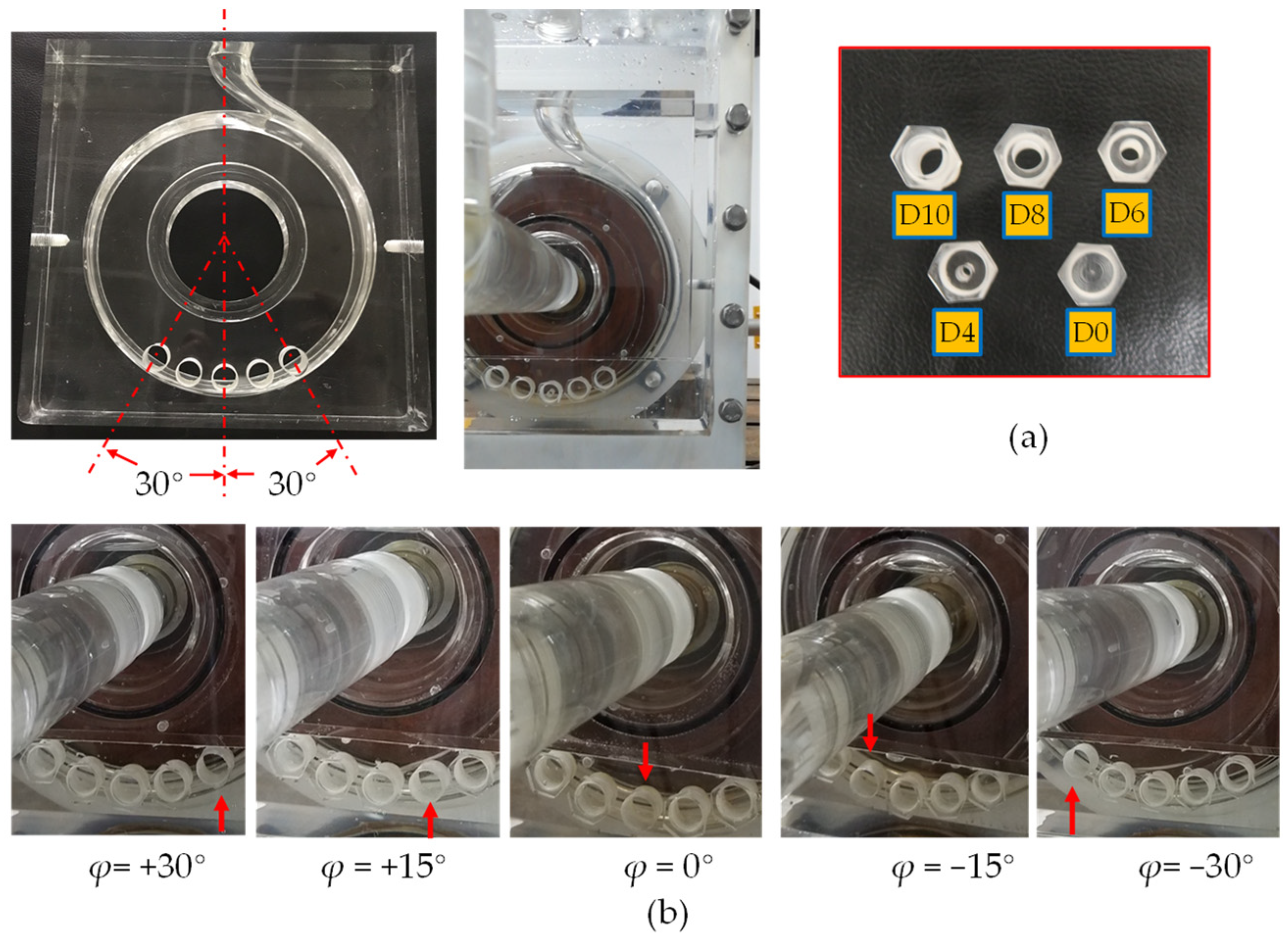
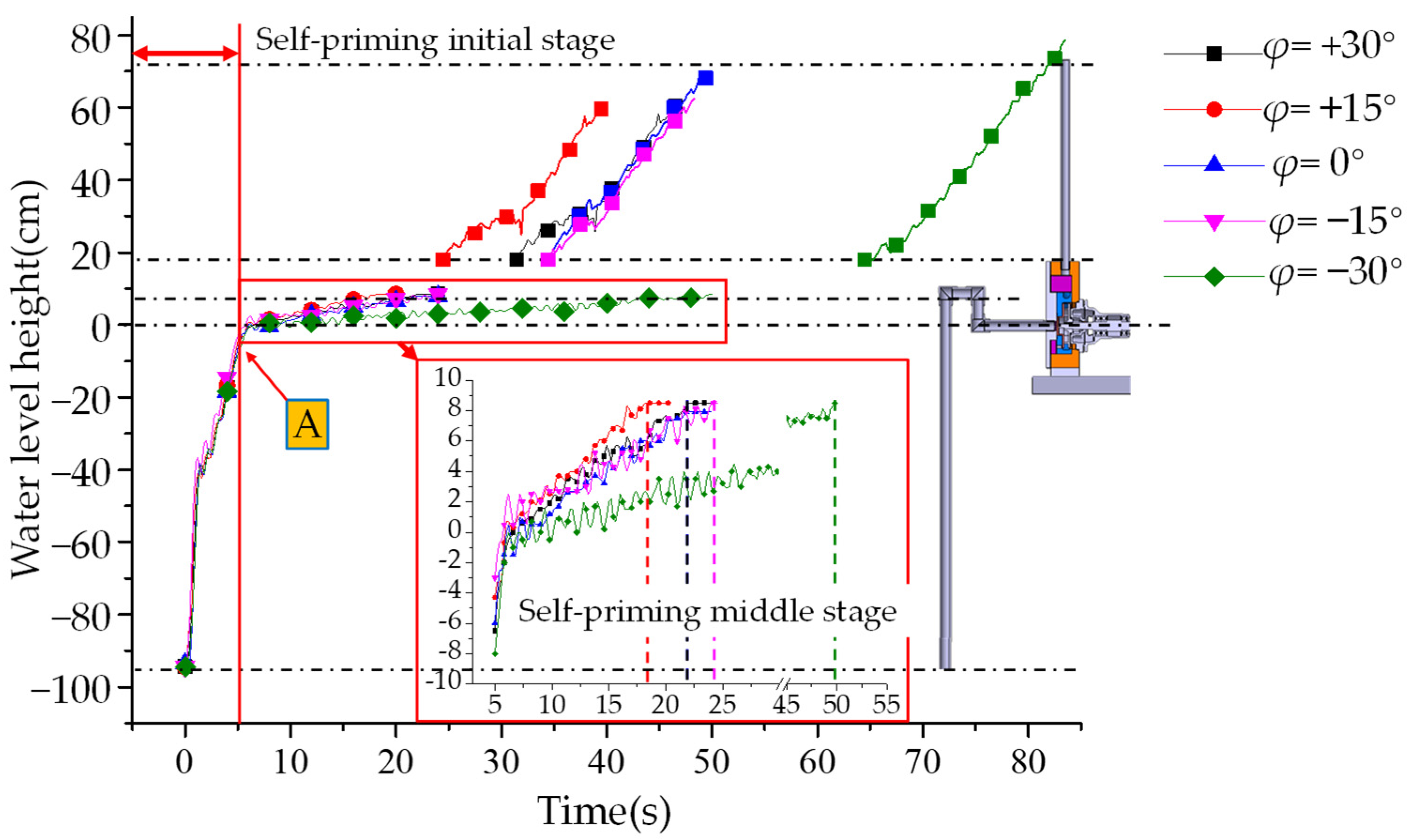
3.1. Influence of Different Reflux Hole Position on Water Level Change during Self-Priming Process

From previous studies [24], we know that the self-priming process was mainly divided into three stages, namely, the initial stage in which the water level in the inlet pipe rises rapidly, the middle stage in which the water level in the inlet pipe rises slowly and causes gas discharge outside the pump, and the last stage in which water flows into the impeller and pumps out to the outlet pipe. Figure 4 shows the water level change laws of the inlet pipe and outlet pipe with different reflux hole positions during the self-priming process. In the first 5 s (self-priming initial stage), the water level of each scheme kept changing synchronously and the water level height was similar. When entering the middle stage of the self-priming process (after point A), the water level rise speed of the inlet pipe was obviously different: the scheme φ = +15° rose the fastest, and reached the top of the inlet pipe at 18 s; the scheme φ = +30°, 0° and −15° rose slowly, and almost all reached the top of the inlet pipe at 24 s; the scheme φ = +30° rose the slowest, the middle stage of the self-priming process being two-times longer than other schemes, and the water level reached the top of inlet pipe at 50 s. In addition, from the time point of the appearance of the liquid phase in the outlet pipe, φ = +15° appeared the earliest, and φ = −30° appeared the latest. The rising speed of the liquid in the outlet pipe was similar, and they all showed a linear rising law. At the same time, it can also be seen from the figure that the speed of the water level rising in the pump (scilicet, the time interval between the water level reaching the top of the inlet pipe and the appearance of liquid in the outlet pipe) was affected by the position of the reflux hole. The time interval was the shortest when φ = +15°, and the time interval was the longest when φ = −30°. In summary, the influence of different reflux hole positions on the middle stage of the self-priming process was the most obvious, and the influence on the initial stage and last stage was relatively weak.

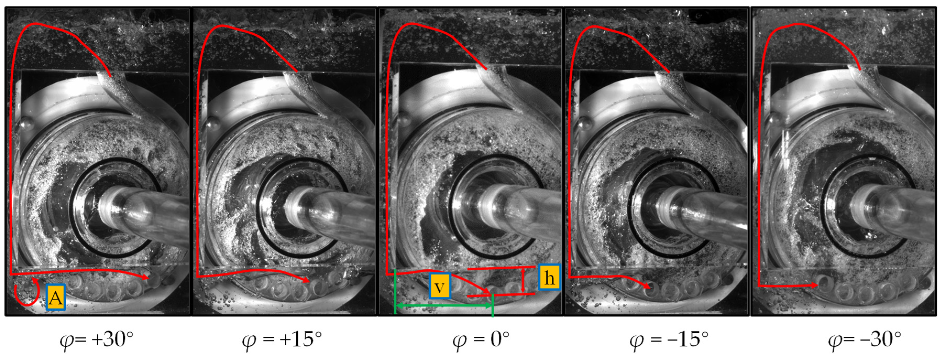
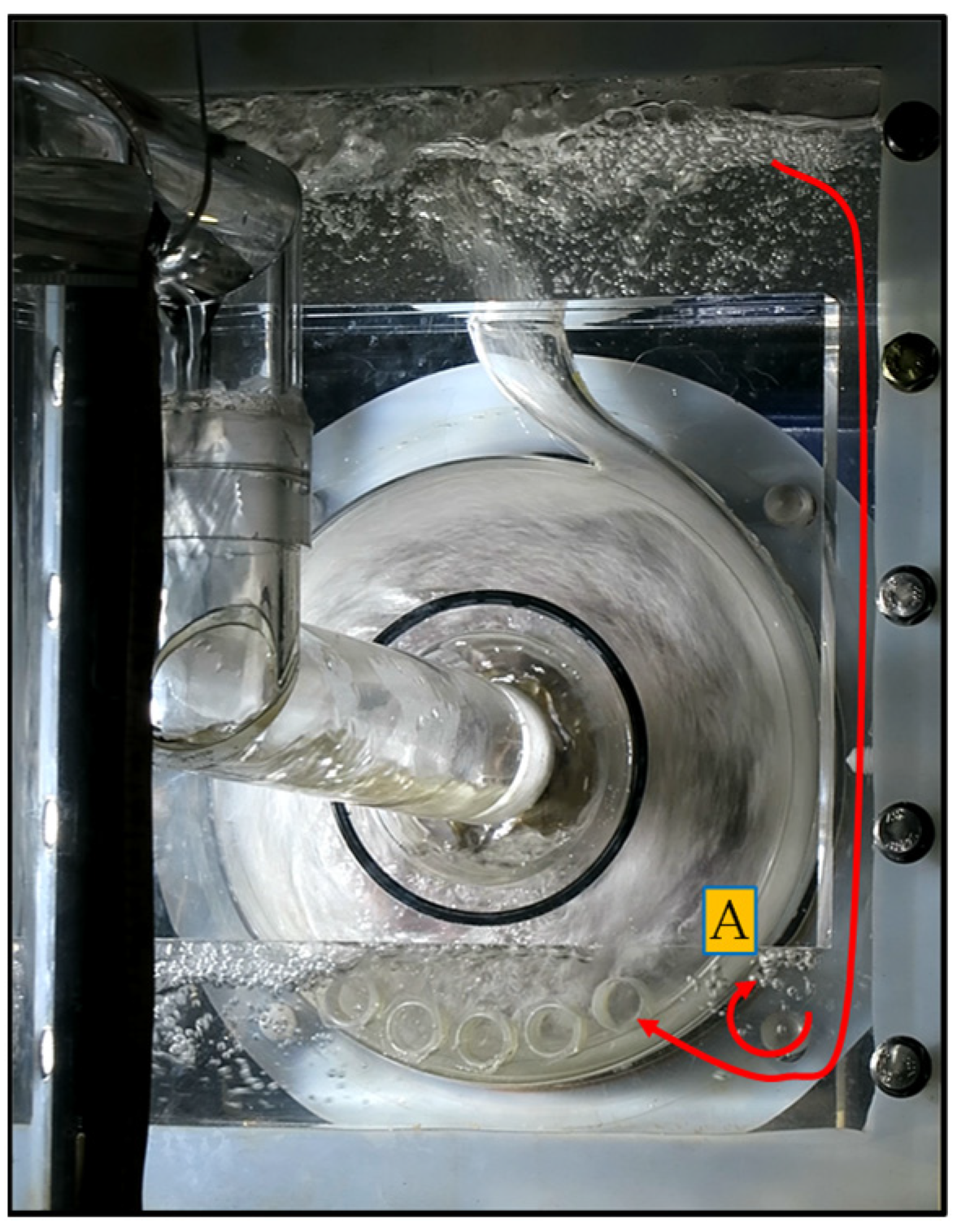
3.2. Influence of Different Reflux Hole Positions on Gas–Liquid Two-Phase Flow Pattern

Figure 5 shows the distribution of gas–liquid two-phase flow pattern in the pump at the 10th seconds, and the red line represents the trajectory of the gas phase after it comes out of the volute. At each return hole position, the gas phase will flow from the gas–liquid separation chamber to the reflux hole in the pump, but different reflux hole positions will make the flow rate different. In general. since the fluid flow direction at the outlet of the volute has a leftward sub-velocity, there is more reflux gas phase in the left flow channel of the pump body. The farther the reflux hole is from the left edge (v), the less gas recirculation, and we obtain a better self-priming performance. At the same time, the gas phase will accumulate under the cover plate and then enter the reflux hole; the farther the reflux hole is from the lower edge of the cover plate (h), the better self-priming performance. From the experimental results, the gas–liquid mixed fluid flowing from the gas–liquid separation chamber to the return hole had a large velocity, which forms a clear vortex at the turning point of the cover plate, so that the influence of the h value on the self-priming performance is less than the v value. Therefore, in this experiment, the self-priming performance of φ = +15° was better than φ = 0°.
According to the above inference, φ = +30° should have better self-priming performance than φ = +15°, which is inconsistent with the test results, so further observation is required. Figure 6 is the trajectory of the air bubbles in the pump during the self-priming process with an angle of +30°. Since the position of the reflux hole φ = +30° is too close to the right side, part of the reflux liquid during the self-priming process comes from the right channel, which makes the air bubbles in the gas–liquid separation chamber accompany the recirculation liquid from the right channel to the reflux hole (A). The movement also formed obvious vortices and bubble aggregation at the corners of the cover plate. The gas phase enters the reflux hole from the right channel, resulting in a decrease of self-priming performance. All in all, when φ = +15°, the experimental pump had the best self-priming performance.

3.3. Influence of Different Reflux Hole Area on Water Level Change during Self-Priming Process

Figure 7 shows the changes in the water level of the inlet and outlet pipes during the self-priming process of self-priming pumps with different diameter reflux holes. It can be seen from the figure that the different schemes had similar rising laws of the water level in the inlet pipe during the self-priming process, rising fast in the initial stage and then decreasing significantly in the middle stage. From second 0 to 5, the water level of the inlet pipe rose rapidly by nearly 100 cm, and in the middle stage of self-priming, the time required for the water level of the inlet pipe to rise by 8.5 cm with different reflux hole areas ranged from 17 s to 94 s. Meanwhile, by comparing the end time of self-priming middle stage in each scheme, it can be found that the diameter of the reflux hole had an optimal size. The water level of the inlet pipe in the scheme of d = 10 mm reached the top of the inlet pipe 2 s earlier than the scheme of d = 12 mm. With the continuous reduction of the diameter of the reflux hole, the time required for the middle stage of self-priming process increased rapidly. When d = 0 mm, it took 99 s for the liquid phase to rise to the top of the inlet pipe. Therefore, the diameter of the reflux hole has little effect on the water level rise rate in the self-priming initial stage, and has a very significant impact on the water level rise rate in the middle stage.
Figure 8 shows the relationship between the area of the reflux hole and the duration of the middle stage of self-priming process. It can be seen from the figure that when the diameter of the reflux hole changed from d = 12 mm to d = 10 mm, the duration of the self-priming middle stage decreased. However, with the further reduction of the reflux hole area, the duration of the self-priming middle stage increased linearly. When the diameter of the reflux hole suddenly decreased from d = 4 mm to d = 0 mm, the duration of the self-priming middle stage increased rapidly from 38 s to 94 s.

3.4. Influence of Different Reflux Hole Area on Gas–Liquid Two-Phase Flow Pattern

Figure 9 shows the gas–liquid two-phase flow in the pump at 10 s for the self-priming pump with different reflux hole areas. It can be seen from the figure that with the reduction of the return hole area, the liquid phase content in the volute and the impeller decreased continuously, and especially the front cavity of the impeller was almost completely occupied by the gas phase. The reduction of the diameter of the reflux hole significantly reduces the return flow of the liquid phase, so that the flow rate of the gas–liquid mixture discharged from the volute to the gas–liquid separation chamber decreased rapidly, which also caused a great decrease in the exhaust performance of the self-priming pump, increasing the self-priming time.
Figure 10 shows the trajectories of the bubbles in the diffuser section with different reflux hole areas. Due to the shape of the diffuser section of the volute, according to the bubble movement laws, it can be divided into two parts: the discharged bubbles and the stagnant swirling bubbles. As the area of the reflux hole decreased, the liquid-phase return volume decreased continuously, which led to the decrease of discharge volume of the gas–liquid mixture in the volute. At the same flow velocity, the flow area of gas–liquid mixture decreased such that the flow area occupied by the stagnant swirling bubbles increased. It can also be clearly seen from the amount of air bubbles at the outlet of the volute that with the decrease of the reflux hole area, the exhaust capacity of the self-priming pump was weakened (A).
In order to fully demonstrate the phenomenon of bubble stagnation and swirling in the diffusion section of the volute, the pump with D = 6 mm was selected as the sample, taking the air bubbles in the diffusion section of the self-priming middle-stage as the research object, and their motion states were tracked by human judgment. Figure 11 is the movement trajectory of the bubbles. Due to the excessive number of bubbles, it is impossible to describe all of them, and four clear and representative bubbles (A, B, C and D) were selected to capture the motion trajectory. It can be clearly seen from the figure that the two bubbles A and B on the left moved rapidly towards the outlet of the volute with the passage of time, while the two bubbles C and D on the right basically stagnated in place, and there was even a trend towards the impeller movement.

4. Conclusions

In order to deeply reveal the self-priming mechanism of the self-priming pump, on the premise of ensuring that the self-priming mechanism is consistent, a visual self-priming pump experimental bench was built. By changing the position and diameter of the reflux hole of the experimental pump, the flow pattern of the gas–liquid two-phase flow in the pump during the self-priming process under different structures was captured, and the influence rule and mechanism of the reflux hole on the performance of the self-priming pump were revealed. This study provides clear advice and experimental support for the selection of reflux hole position and diameter in the design process of self-priming pumps [25]. The specific conclusions are as follows:
(1)
The research fully proved that the change of the reflux hole structure parameters affects the self-priming performance of the self-priming pump by affecting the gas–liquid two-phase backflow rate during the self-priming process.
(2)
Since the outlet of the volute was not vertically upward, there was a lateral component velocity when liquid flowed out of the volute, which led to the uneven distribution of the pump body velocity. Therefore, the reflux hole in different positions will lead to the change of gas–liquid two-phase back flow rate in the pump chamber, thus affecting the self-priming pump performance. In this study, the self-priming performance was best when reflux hole was at +15°, and worst when reflux hole was at −30°.
(3)
The area of the reflux hole mainly affected the composition of the backflow gas–liquid mixture in the pump. With the increase of the area of the reflux hole, the self-priming time of the centrifugal pump first decreased and then increased; an excessively large reflux hole increased the gas flow back, while a too-small reflux hole limited the liquid flow back hole. The optimal diameter of the reflux hole in this study was d = 10 mm.
(4)
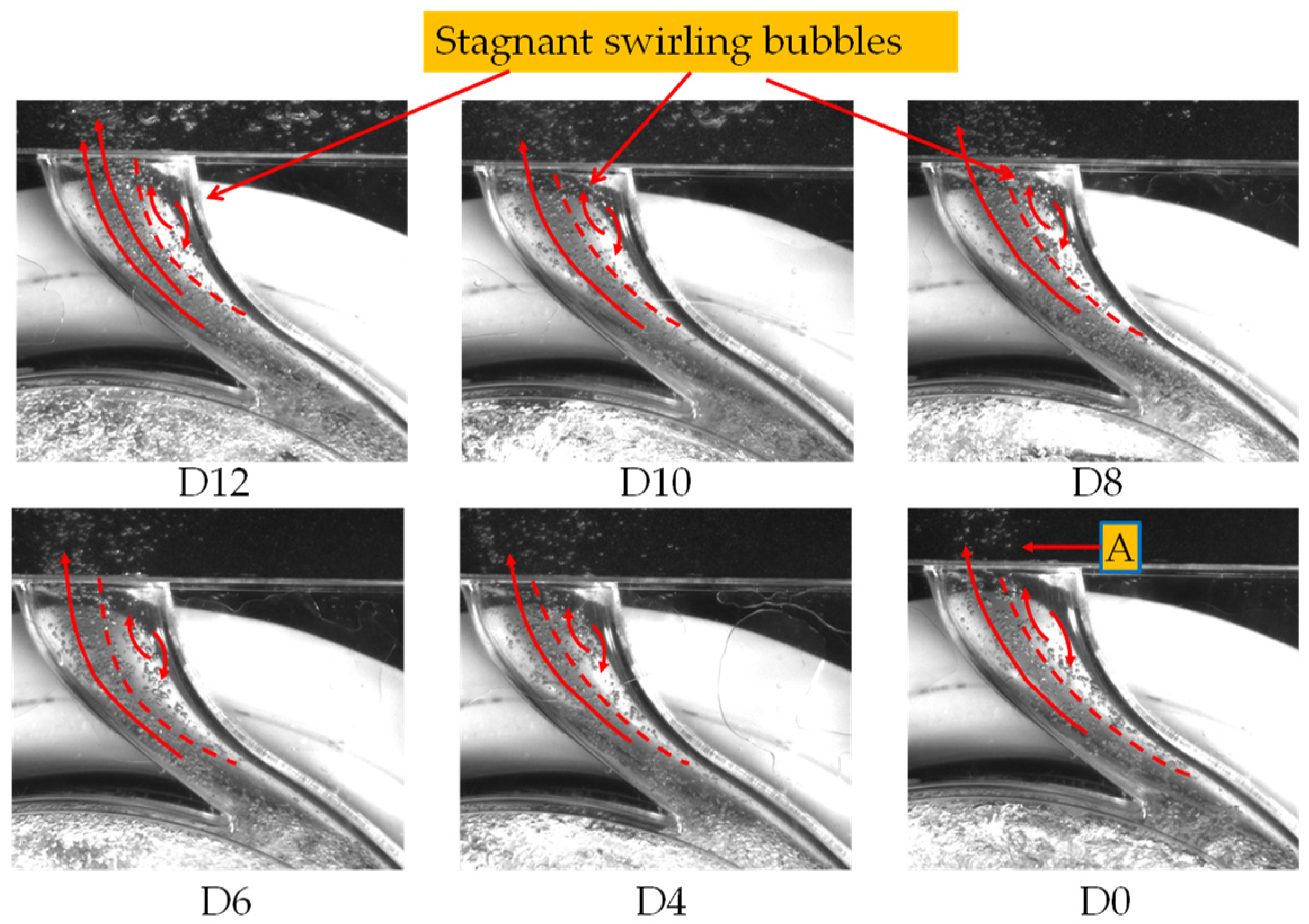
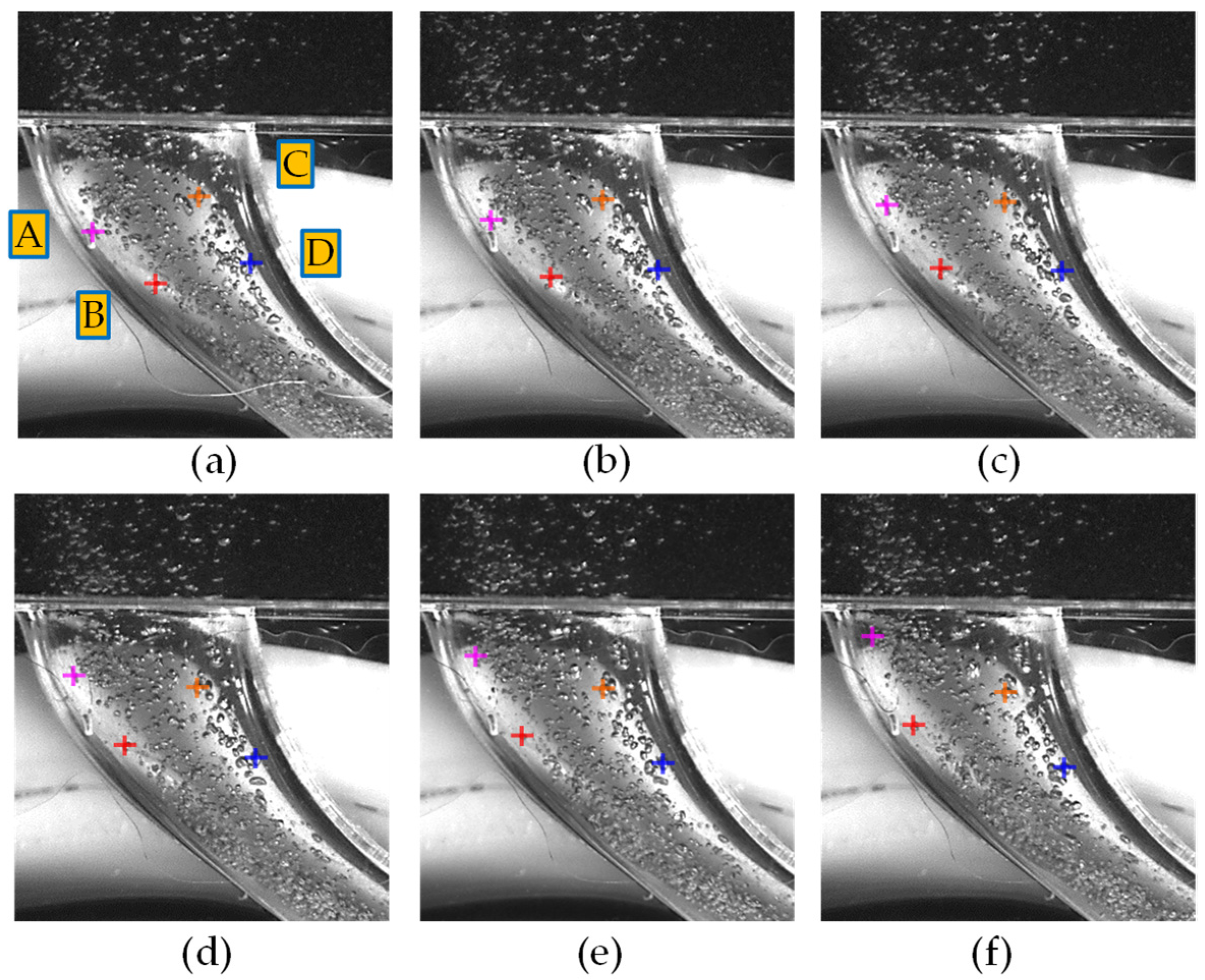
In the diffuser of the volute, as the area of the reflux hole decreased, the area of stagnant swirling bubbles expanded. Tracing specific bubbles showed that due to the structure of the volute, the stagnant swirling bubbles are mainly concentrated on the right side of the diffuser.
(5)
Although this paper fully revealed the gas–liquid two-phase flow pattern in the pump during the self-priming process, due to lots of bubbles in the pump, serious overlap, and small volume, the evolution characteristics of the bubbles during the self-priming process were not quantitatively analyzed. Bubble image processing and analysis can be the main content of subsequent research.

Author Contributions

Conceptualization, H.Q., J.M. and D.W.; methodology, H.Q., J.M. and D.W.; validation, H.Q., D.W. and Z.Z.; investigation, H.Q. and J.J.; resources, H.Q., J.J. and Z.Z.; data curation, H.Q. and Z.Z.; writing—original draft preparation, H.Q.; writing—review and editing, H.Q. and C.X.; visualization, H.Q.; supervision, C.X. and D.W.; project administration, J.M. and P.Z.; funding acquisition, C.X., D.W., P.Z. and J.M. All authors have read and agreed to the published version of the manuscript.

Funding

This research was funded by Key R&D Program of Zhejiang, grant number 2022C02035; The National Natural Science Foundation of China, grant number 51976202; The Welfare Technology Applied Research Project of Zhejiang Province, grant number LGG21E090003; Zhejiang Provincial Natural Science Foundation, grant number LGG21E090002, L2JWY22E060001; Scientific research foundation of Zhejiang University of Water Resources and Electric Power, grant number xky2022043.

Institutional Review Board Statement

Not applicable.

Informed Consent Statement

Not applicable.

Data Availability Statement

Not applicable.

Conflicts of Interest

The authors declare no conflict of interest.

References

  1. Zhang, Y.; Zhu, Z.; Zhao, Y.; Wu, J.; Zhou, F. Comparative experiments on a self-priming pump delivering water medium during rapid and slow starting periods. Iran. J. Sci. Technol. Trans. Mech. Eng. 2020, 45, 1007–1019. [Google Scholar] [CrossRef]
  2. Wu, D.; Zhu, Z.; Ren, Y.; Gu, Y.; Zhou, P. Influence of blade profile on energy loss of sewage self-priming pump. J. Braz. Soc. Mech. Sci 2019, 41, 470. [Google Scholar] [CrossRef]
  3. Yao, H.; Zhang, Y.; Wu, D.; Wu, P. Numerical study on hydraulic and self-priming performance of a double-stage self-priming pump. IOP Conf. Ser. Earth Environ. Sci. 2018, 163, 012039. [Google Scholar] [CrossRef]
  4. He, C.; Gu, Y.; Zhang, J.; Ma, L.; Yan, M.; Mou, J.; Ren, Y. Preparation and modification technology analysis of Ionic Polymer-Metal Composites (IPMCs). Int. J. Mol. Sci. 2022, 23, 3522. [Google Scholar] [CrossRef] [PubMed]
  5. Gu, Y.; Yu, L.; Mou, J.; Wu, D.; Xu, M.; Zhou, P.; Ren, Y. Research strategies to develop environmentally friendly marine antifouling coatings. Mar. Drugs 2020, 18, 371. [Google Scholar] [CrossRef] [PubMed]
  6. Mou, J.; Zhang, F.; Wang, H.; Wu, D. Influence of the area of the reflux hole on the performance of a self-priming pump. Fluid Dyn. Mater. Proc. 2019, 15, 187–205. [Google Scholar] [CrossRef]
  7. Kim, S.; Sohn, C.; Hwang, J. Effects of tube diameter and submergence ratio on bubble pattern and performance of air-lift pump. Int. J. Multiphas Flow 2014, 58, 195–204. [Google Scholar] [CrossRef]
  8. Shao, C.; Li, C.; Zhou, J. Experimental investigation of flow patterns and external performance of a centrifugal pump that transports gas-liquid two-phase mixtures. Int. J. Heat Fluid Flow 2018, 71, 460–469. [Google Scholar] [CrossRef]
  9. Stel, H.; Ofuchi, E.; Sabino, R.; Ancajima, F.; Bertoldi, D.; Neto, M.; Morales, R. Investigation of the motion of bubbles in a centrifugal pump impeller. J. Fluid Eng. 2019, 141, 031203. [Google Scholar] [CrossRef]
  10. Barrios, L.; Prado, M. Experimental Visualization of two-phase flow inside an electrical submersible pump stage. J. Energ. Resour. 2011, 133, 042901. [Google Scholar] [CrossRef]
  11. Barrios, L.; Prado, M. Modeling two-phase flow inside an electrical submersible pump stage. J. Energ. Resour. 2011, 133, 042902. [Google Scholar] [CrossRef]
  12. Verde, W.; Biazussi, J.; Sassim, N.; Bannwart, A. Experimental study of gas-liquid two-phase flow patterns within centrifugal pumps impellers. Exp. Therm. Fluid Sci. 2017, 85, 37–51. [Google Scholar] [CrossRef]
  13. Zhang, J.; Cai, S.; Zhu, H.; Zhang, Y. Experimental investigation of the flow at the entrance of a rotodynamic multiphase pump by visualization. J. Petrol. Sci. Eng. 2015, 126, 254–261. [Google Scholar] [CrossRef]
  14. Shu, X.; Ren, Y.; Wu, D.; Zhu, Z.; Mou, J. Energy loss and unsteady flow characteristics in a self-priming pump. J. Hydraul. Eng. 2019, 50, 1010–1020. [Google Scholar]
  15. Wang, C.; Hu, B.; Zhu, Y.; Wang, X.; Luo, C.; Cheng, L. Numerical study on the gas-water two-phase flow in the self-priming process of self-priming centrifugal pump. Processes 2019, 7, 330. [Google Scholar] [CrossRef] [Green Version]
  16. Wang, C.; He, X.; Zhang, D.; Hu, B.; Shi, W. Numerical and experimental study of the self-priming process of a multistage self-priming centrifugal pump. Int. J. Energy Res. 2019, 43, 4074–4092. [Google Scholar] [CrossRef]
  17. Cheng, X.; Wang, J.; Liu, M. Influence of reflux hole position and area on performance of vertical self-priming pump. J. Huazhong Univ. Sci.Tech. 2022, 50, 63–68. [Google Scholar]
  18. Qian, H.; Mou, J.; Ren, Y.; Zhu, Z.; Liu, N.; Zheng, S.; Wu, D. Investigation of self-priming process of a centrifugal pump with double blades. J. Therm. Sci. 2021, 30, 849–858. [Google Scholar] [CrossRef]
  19. Chang, H.; Shi, W.; Li, W.; Liu, J. Energy loss analysis of novel self-priming pump based on the entropy production theory. J. Therm. Sci. 2019, 28, 306–318. [Google Scholar] [CrossRef]
  20. Li, G.; Wang, Y.; Mao, J. Numerical investigation on the gas-liquid entraining and separating effects on self-priming performance in a flow-ejecting centrifugal pump. Proc. Inst. Mech. Eng. Part A J. Power Energy 2019, 233, 232–248. [Google Scholar] [CrossRef]
  21. Li, H.; Li, S.; Lu, T. High-speed photography experiment on transient air—Water flow in self-priming centrifugal pump with separation chamber. J. Drain Irrig. Mach. Eng. 2019, 37, 375–380. [Google Scholar]
  22. Li, H.; Lu, T.; Zhang, L. Influence of gap between impeller and tongue on centrifugal pump self-priming performance. Trans. Chin. Soc. Agric. Mach. 2017, 48, 141–147. [Google Scholar]
  23. Li, H.; Jiang, B.; Lu, T. Visualization experiment of gas-liquid two-phase flowofpumpduringself-priming process. Trans. Chin. Soc. Agric. Mach. 2015, 46, 59–65. [Google Scholar]
  24. Qian, H.; Mou, J.; Wu, D.; Ren, Y.; Zhu, Z. Experimental investigation on the gas-liquid flow patterns in a centrifugal pump during self-priming process. AIP Adv. 2020, 10, 015136. [Google Scholar] [CrossRef]
  25. Luo, H.; Zhou, P.; Shu, L.; Mou, J.; Zheng, H.; Jiang, C.; Wang, Y. Energy Performance Curves Prediction of Centrifugal Pumps Based on Constrained PSO-SVR Model. Energies 2022, 15, 3309. [Google Scholar] [CrossRef]
Figure 1. Test pump structure. (a) Comparison of critical fluid domains between actual product and the test pump; (b) transparent part of the test pump.
Energies 15 04617 g001
Figure 2. Reflux hole design details. (a) Reflux hole plug with different diameters; (b) Reflux hole with different position.
Energies 15 04617 g002
Figure 3. Visualization test bench.
Energies 15 04617 g003
Figure 4. Water level change law with different reflux hole positions.
Energies 15 04617 g004
Figure 5. Flow pattern in pump with different reflux hole positions.
Energies 15 04617 g005
Figure 6. Gas phase reflux in the right channel of pump body.
Energies 15 04617 g006
Figure 7. Water level change law with different reflux hole diameters.
Energies 15 04617 g007
Figure 8. The relationship between the area of reflux hole and the time of the self-priming mid-stage.
Energies 15 04617 g008
Figure 9. Gas–liquid distribution in the pump at 10 s.
Energies 15 04617 g009
Figure 10. Bubble trajectory in volute at 10 s with different reflux areas.
Energies 15 04617 g010
Figure 11. Bubble tracking at the volute diffuser. (a) 9.587 s, (b) 9.587 s + Δt, (c) 9.587 s + 2Δt, (d) 9.587 s + 3Δt, (e) 9.587 s + 4Δt, and (f) 9.587 s + 5Δt.
Energies 15 04617 g011
Table 1. Parameters of the test pump and high-speed camera.
ParameterValue
Model pump
Flow rate Qd (m3/h)5
Total head Hd (m)6
Rotation speed n (r/min)1680
Specific speed nq59.6
Impeller inlet diameter D1 (mm)60
Impeller outlet diameter D2 (mm)158
Blade outlet width b2 (mm)16
Number of blades z2
Warp angle φ (deg)255
Area of reflux hole S (mm2)113
High speed camera
Sensor typeCMOS
Maximum resolution1920 × 1080
Pixel size (μs)11 × 11
Maximum frame rate (full resolution) (fps)2128
Exposure time (ms)0.0015–40
Pixel scan speed (MHz)55
RAM (GB)36
Interframe space (μs)3.15
Publisher’s Note: MDPI stays neutral with regard to jurisdictional claims in published maps and institutional affiliations.

