Review

Future Technology Mix—Enhanced Geothermal System (EGS) and Carbon Capture, Utilization, and Storage (CCUS)—An Overview of Selected Projects as an Example for Future Investments in Poland

by
Anna Sowiżdżał
,
Magdalena Starczewska
* and
Bartosz Papiernik
Faculty of Geology, Geophysics and Environmental Protection, AGH University of Science and Technology, Mickiewicza 30, 30-059 Krakow, Poland
*
Author to whom correspondence should be addressed.
Energies 2022, 15(10), 3505; https://doi.org/10.3390/en15103505
Submission received: 13 April 2022 / Revised: 29 April 2022 / Accepted: 7 May 2022 / Published: 11 May 2022
(This article belongs to the Special Issue Geothermal Systems)

Abstract

:
Rising fuel prices, changes in energy markets, and concern for the environment make it necessary to develop new solutions and technologies. The development of new technologies brings with it the need to take risks associated with unpredictable consequences, technological immaturity, and other issues. However, without these elements, technological development is not possible. In this study, installations related to two different technologies—Enhanced Geothermal System (EGS) and Carbon Capture, Utilization, and Storage (CCUS)—are reviewed. An Enhanced Geothermal System is a technology for exploiting the energy stored in hot dry rocks. Carbon Capture, Utilization, and Storage is an important technology for reducing CO2 emissions. The combination of these two technologies in CO2–EGS systems can bring significant environmental benefits. This paper reviews the most important CCUS and EGS systems in the world to form a baseline for similar, future technology investment in Poland.

1. Introduction

In the 21st century, increasing importance is being attached to achieving climate neutrality, meaning an economy with zero net greenhouse gas emissions. The European Union is pursuing an ambitious policy aimed not only at reducing emissions but also at the intensive sequestration and storage of CO2 in almost all industrial processes.
The growing demand for energy, and the desire to eliminate fossil fuels from the energy sector and reduce CO2 emissions into the atmosphere, lead to the search for new, ecological energy sources. One of them is geothermal energy. Heat is generated by the natural processes of decomposition of radioactive elements in the earth’s crust and by absorbing sunlight. The location of conventional geothermal power plants depends on the presence of hot aquifers. Unconventional geothermal systems (EGS—Enhanced Geothermal System) are based on hot, impermeable dry rock (HDR—Hot Dry Rock); therefore, this technology can be used all over the world [1].
The review of EGSs has been carried out as an important part of preparations for the launch of such a system in Poland. In Poland, geothermal water and energy is currently used in hydrogeothermal systems for heat production and in recreational pools and balneotherapy [2]. No EGS installation has been established in Poland, although research on identifying geothermal potential for EGSs has been ongoing since 2010 [3,4,5,6,7,8]. In order to identify the potential of EGSs in Poland, the geological structure in areas of current EGS installations was analyzed. A nearby place with geological analogy is Groß Schönebeck in Germany. In the North East German Basin, 4000 m-deep Lower Permian sandstones and volcanic rocks are explored for geothermal energy production. A research strategy is developed and applied using the geothermal in situ laboratory Groß Schönebeck [9]. The EGS installation in Ogachi (Japan) is also an interesting location for the project currently under development in Poland, due to the use of carbon dioxide instead of water as the medium.
The subject of CO2 utilization as a medium in EGSs is currently being investigated by an international consortium within the EnerGizerS project. The project (full name CO2–Enhanced Geothermal Systems for Climate Neutral Energy Supply), is a part of the POLNOR 2019 Polish–Norwegian research projects financed under Norway Grants via the National Centre for Research and Development. The main goal of the project is development of EGSs with CO2 instead of water as the working fluid. Analysis of key parameters [10], together with analysis of geothermal conditions in both countries, made it possible to indicate suitable geological structures for the CO2–EGS system. In Poland, the area of the Gorzów block was pointed out as one of the most favorable for this system. The site was selected because of the geological analogy to the volcanic reservoir located in Groß Schönebeck near Berlin, where an EGS project is being carried out. The Gorzów Block region has exceptionally favorable thermal conditions, manifested by a geothermal gradient of 3.5 °C/100 m and a high temperature of 150 °C at a depth of 4.3 km [11].
An Enhanced Geothermal System using supercritical carbon dioxide as the working fluid (CO2–EGS) is an interesting alternative due to the added benefit of geological storage of CO2 during geothermal energy extraction. This technology could become important for achieving international targets for mitigating anthropogenic climate change. It is an innovative and future-oriented solution. The remarkable advantage of these systems is that they contribute to climate protection by producing clean geothermal energy and simultaneously eliminating carbon dioxide emissions from the burning of fossil fuels. CO2–EGS systems combine both Enhanced Geothermal Systems and Carbon Capture, Utilization, and Storage technologies.
Intensive works on carbon capture and storage started in the world at the beginning of the 21st century. They were run first of all by governments and, to a lesser extent, by industry too. This allowed the assessment of CCS storage capacities by 2011 in many countries of the world. In Europe, cross-over from volume assessments to real CCS storage was rapidly stopped at this time, due to social protest. Intensive pilot works in commercial scale were continued at this time in Norway, comprising offshore aquifer sites Sleipner [12] in the Norway Sea (storage ~1 Mpta since 1996 by a single well drilled into the saline Utsira Formation) and Snohvit (~0.7 Mtpa since 2007) in the Barents Sea. Up to 2019, a total of around 22 Mtpa of CO2 had been captured and stored at these facilities [13].
A review of global experience is a very important and necessary element for planning new EGS installations as well as for CCUS. The combination of both technologies can bring significant environmental benefits.

2. An Enhanced Geothermal System
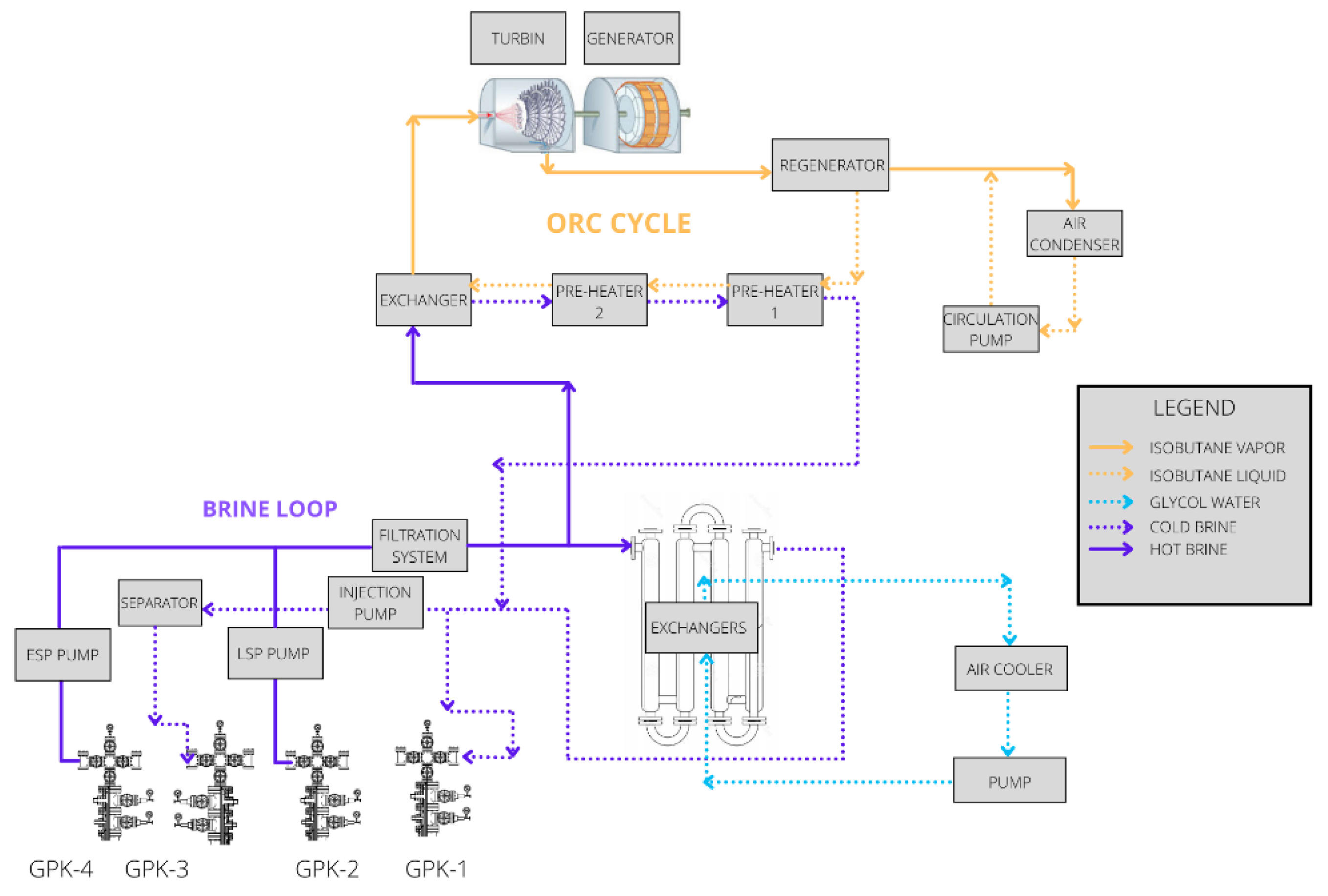
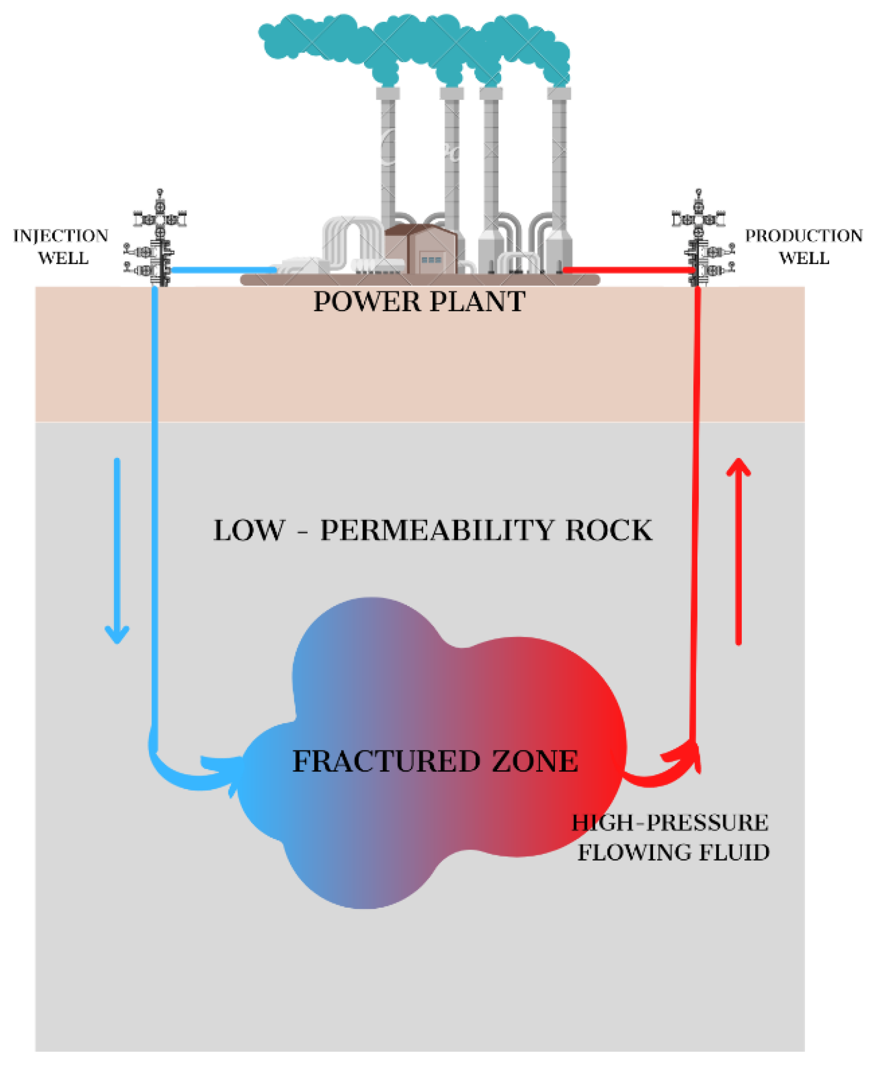
2.1. EGS Technology

The energy of hot dry rocks is used in the world by means of EGS—Enhanced Geothermal System technology. Unlike classic hydrogeothermal systems, this technology enables the extraction of energy from dry rocks that do not contain water or contain water in small amounts (Figure 1). This is done by artificially increasing the hydraulic capacity of a geothermal reservoir, and then introducing a working fluid into it, which is an energy carrier, and bringing it to a power plant or combined heat and power plant [14].
The EGS technology was developed in the 1970s in the United States, when a group of scientists from Los Almos National Laboratories created the world’s first installation in Fenton Hill. Since then, research has been conducted around the world on the application of this technology [17].
EGSs utilize the heat of the earth in closed geothermal systems by artificially increasing the hydraulic capacity of the geothermal reservoir. Two common working fluids are used in EGS: water (H2O) and carbon dioxide (CO2) [18]. Water is the standard medium and most systems in the world use it. Currently, there are few experiments on the use of CO2 instead of water as a heat transfer fluid, but previous studies confirm that CO2 as a medium in EGSs would be very attractive [19,20,21,22]. This is due to the good thermodynamic properties of CO2 and the need to reduce carbon dioxide emissions into the atmosphere.
EGSs are geothermal reservoirs with low-permeability conductive dry rocks or low-productivity convective aquifers [23]. The ranges of hydrothermal and petrothermal systems overlap, with a continuous transition between both (Figure 2).

2.2. An Overview of EGS Installation over the World

In various parts of the world (Figure 3), i.e., Habanero EGS Project, Hijiori, Pohang, Ogachi, Basel, Rosemanowes, Soultz-sous-Forêts, Groß Schönebeck, Fenton Hill, there are EGS projects in different phases of implementation. Seven of them have ceased to operate, but most of them continue. This paper reviews the most important EGSs in the world. These projects are located in the European Union, Japan, South Korea, Australia, and the United States.
The Table 1 summarizes the most important parameters of the analyzed installations.
The described world projects show the application of EGS technology in various parts of the world. The conducted observations and research are valuable experiences that can be used in future installations.

2.2.1. EGS Installation in Europe

Great Britain—Rosemanowes

Rosemanowes Quarry is located near Penryn in Cornwall, UK. The location was chosen due to the knowledge of the ground (there are mines nearby). The project was funded by the UK Department of Energy and the European Communities Commission. Due to the low temperature (below 100 °C), the project was never intended to produce energy, but only to investigate the network of fissures in the rocks. In the first phase of the project, in 1977, several test wells were drilled to a depth of 300 m, however, it turned out that the stress fields are not representative of those at greater depths.
In the next stage, two wells were drilled—RH11 (production well) and RH12 (injection well), with a depth of about 2000 m and a temperature of 80–90 °C. At a later stage, hydraulic fracturing of the RH12 well was performed. The reservoir was expected to expand upstream from the RH12 well, but instead the fracture widened downward, which resulted in poor interconnection between the wells. During the nine-month circulation, the reservoir continued to dredge. Tests on the RH12 well showed that it was not suitable for modeling a full-size HDR well.
In the third phase of the project (2B), the RH15 (production) well, 2600 m deep and 100 °C, was drilled into a reservoir already built in Phase 2 of the project. Hydraulic fracturing was performed, the RH12 well remained an injection well, and circulation tests began in 1985 and continued for the next four years. Various flows were obtained, mostly 20–25 kg/s. During this period, the temperature dropped from 80 °C to 70 °C. When injecting 5 kg/s, a flow in the production well of 4 kg/s and a pressure of 4 MPa were obtained, while when injecting 24 kg/s, only 15 kg/s was obtained in the production well, and a pressure of 10.5 MPa.
Due to the excessively high pressures, a gap was formed, cold water returned too quickly from the production well, and increasing water losses were also observed. In the later stages of the project, efforts were made to reduce the water loss, but this enlarged the fracture and led to a further temperature reduction [14,25].

Switzerland—Basel

The project started in 1995 under the patronage of the Swiss Federal Ministry of Energy. Basel is in the northwest of Switzerland at the south-eastern end of the Upper Rhine Trench [26].
The power plant was designed to produce electricity with a capacity of 3 MW and heat with a capacity of 20 MW. Two wells (production and injection) were made to a depth of 5 km. The temperature in the production well was 170 °C, while the injection temperature was 70 °C. Originally, the maximum flow was supposed to be 70 kg/s, however, it was reduced to 50 kg/s.
The first well was made in the Otterbach area. Drilling problems were encountered at approximately 1500 m, forcing contractors to stop working on the well. The geothermal gradient measured in the well was 42 °C/km, and eventually the well was used for seismic monitoring. Another borewell (OT-2) was completed in 2001, and it reached 2755 m. By 2006, works related to the installation of seismic monitoring to a depth of 2700 m were completed [14,26].
The Basel-1 borewell was completed in October 2006. It was 5000 m deep. Up to 2500 m, sedimentary rocks dominate in the geological profile, and below this depth there are granites. The well stimulation started in December 2006 using water from the River Rhine. Initially, the water was pumped in at a flow of 1.67 kg/s, and a pressure at the head of the gull was reached of 110 bar. After six days, a total of 12,000 m3 of water was pumped into the well, achieving a pressure at the well head of up to 300 bar and a flow of 55 kg/s. Several days after stimulation, increased seismic activity was observed, an event with a magnitude of 2.7 was recorded, and after this event, the stimulation of the well was stopped. A few hours later, an earthquake with a magnitude of 3.4 was recorded. More than 13,500 seismic events were recorded within a few months of the well being stimulated. After the conducted research and analyses, the project was completed in 2009 [27].

France—Soultz-Sous-Forêts

The European EGS project is in Soultz-sous-Forêts, Alsace, France. The research was started in 1987 at the request of the European Commission in order to search for new sources for energy production. The main idea of the project was to obtain energy stored at great depths in hot dry rocks. These areas were selected for research due to the observed large temperature anomalies in oil wells [28].
The test site is in the Lower Rhine Trench belt, which is part of the European Rift Zone, stretching from Mainz (central Germany) to Basel (Switzerland). Up to a depth of 1400 m, there is a layer of sedimentary rocks, and beneath them there is a crystalline substrate composed of granites. The surface gradient is about 110 °C/km. The temperature gradient for this area was determined using measurements made in oil wells. This gradient is variable, and for the first 900 m it is about 10.5 °C/100 m, decreasing to 1.58 °C/100 m at a depth of 2350 m, then increasing to 3 °C/100 m at a depth of 5000 m [29].
Figure 4 shows a brief history of the developing of the EGS power plant in Soultz-sous-Forêts. The graphic also shows the depth of the wells and their trajectory.
In the initial phase (1987–1989), a well (GPK-1) was drilled to the level of 2000 m to reach the granite layer at 1377 m. The temperature at this depth was 140.3 °C. In the years 1992–1993, the GPK-1 well was deepened to the level of 3590 m. In 1995, drilling of the GPK-2 well to the level of 3876 m was started, reaching the temperature of 168 °C. The next stage was stimulation at the flow of 50 kg/s and pressure of 10 MPa. The monitoring showed an upward trend of the stimulated reservoir to an area of 0.24 km3, and a connection between the wells was noticed. A circulation test between GPK-1 and GPK-2 was performed. The flow was increased from 12 kg/s to 56 kg/s. In 1999, the GPK-2 well was deepened to the level of 5084 m. Further wells were made in 2002 (GPK-3, 5031 m) and 2004 (GPK-4, 5105 m). The power plant was built in 2008–2009 [14].
Installed capacity of the power plant is 1.7 MW. The assessed geothermal system is based on three wells: production wells GPK-2 and GPK-4 and injection well, GPK-3, while well GPK-1 is the first injection well, which is currently not used, and EPS 1 serves as a research well [14,30].
The diagram (Figure 5) shows the construction of a binary power plant installed in Soultz. Hot brine flows to the well head, reaching a temperature of about 150 °C at a pressure of 23 bar and a flow of 30 kg/s. Obtaining such flow parameters is possible with the use of a pump (Line Shaft Pump). After filtering, it travels to a system of tubular exchangers, supplying heat to the electricity production circuit. The installation uses the Organic Rankine Cycle (ORC), in which the working medium is isobutane. After cooling to a temperature of around 70 °C, the brine is directed to the injection well. Due to the low availability of aquifers in the vicinity of the power plant, the entire system is air-cooled. Since 2016, the power plant has been producing electricity on an industrial scale [1].

2.2.2. EGS Installation in Asia

Japan—Hijiori

The HDR (Hot Dry Rock) project in Hijiori started in 1985 and was completed in 2002. The project was sponsored by NEDO (Japan’s New Energy and Industrial Technology Organization). This institution participated in the project of the world’s first EGS installation—Fenton Hill in the USA [14].
The installation is located in the northern part of the Honshu Island, about 1 km from the town of Hijiori. The research area is located on the southern rim of the Gassan volcano caldera, about 2 km in diameter. The installation consists of four wells: HDR-1, HDR-2, HDR-3, and SKG-2. In the lithological profile of the area, seven rock units were distinguished consisting of volcanic formations and granodiorites, which are below the depth of 1500 m [32].
Stage I started in 1986. First, an “upper reservoir” was created at the level of 1800 m (estimated temperature −250 °C), then it was fractured through the SKG-1 borewell. In 1987–1990, further borewells were drilled. The final stage of phase I of the project was a 90-day circulation test between the SKG-2 (injection) well and HDR-1, HDR-2, and HDR-3 as production wells. After about 50 days, stable conditions were achieved, and it was found that the flow in the HDR-2 and HDR-3 well was twice as high as in HDR-1. The injection temperature obtained from the storage tank was about 50 °C, and the maximum temperature obtained from the production wells was, successively: 190 °C (HDR-1), 150 °C (HDR-2), and 165 °C (HDR-3). The result of the stimulation was to obtain a maximum flow of about 13.9 kg/s. The possible maximum thermal power to be obtained was 8 MW, and the power of a binary power plant for electricity production from 0.8 MW to 1 MW [14].
In the second stage of the project, a “lower reservoir” was created at a depth of 2200 m (estimated temperature −270 °C). The HDR-1 well was deepened, and its purpose changed from production to injection. The direction of the HDR-2 well was changed and deepened, and renamed HDR-2a [9]. In 2001–2002, an annual system circulation test was carried out. The injection temperature into the HDR-1 well was 36 °C, and the flow was 15–20 kg/s. From the HDR-2a production well, the temperature was 163 °C with a flow of 5 kg/s, and from the HDR well-3, 172 °C with a flow of 4 kg/s. The total thermal energy production was around 8 MW, and the power of the commissioned binary power plant was 130 kW. During the test work, problems were encountered with the precipitation of anhydrite (CaSO4) in HDR-2a and HDR-3 production wells, which required well cleaning [14,17].

Japan—Ogachi

The Ogachi EGS Project is in the north of Honshu, near the Kurikoma National Park. The first phase of the project began in 1986, when an appraisal well was drilled to a depth of 400 m. The measured temperature at the trim level was 60 °C. Using the method of hydraulic stimulation, three reservoirs were also created at a depth of 362 m, 374 m, and 400 m. The production well was made in 1988. The aim of the second phase of the project was to create two large reservoirs at different depths. In 1990, the OGC-1 well was drilled. Initially, it was 990 m deep, eventually deepened to 1000 m, and the temperature at this level was measured to 228 °C. As in the case of Hijiori, two tanks were created—lower and upper. In 1999, the OGC-3 well was drilled to a depth of 1300 m. In the years 2000–2002, water flow and borewell tests were carried out. However, due to financial reasons, the project was terminated in 2002. In 2006, research began on the possibility of geological CO2 storage in rock structures at the Ogachi Project site. Water with CO2 was pumped into the OGC-1 well at a pressure of 15 MPa and a flow of 6.3 kg/s. A fluid with a temperature of 127 °C was obtained from the OGC-2 production well. The OGC-3 well was used as an observation well. Another test was carried out in 2007, which involved injecting CO2 with a mixture of dry ice and water into the OGC-2 well. Carbon dioxide was observed to precipitate out as carbonates. The experiment was to check how the medium in the form of CO2 would behave in rock formations. The final result was the creation of a model of CO2 injection into injection or production wells in EGS reservoirs [14,33].

South Korea—Pohang

A pilot project for the EGS installation in South Korea was started in December 2010 near the city of Pohang. The project was implemented by the NexGeo company (Soeul, Korea). The budget was estimated at around KRW 43 trillion (South Korean won), 40% financed by the Korean government from funds for the development of renewable energy and 60% by Korean industry. The first layer of the terrain consists of tertiary partially consolidated silts, lying to a depth of between 200 m and 400 m. The next level is made up of chalky sedimentary rocks (sandstones and siltstones) with small amounts of volcanic rock. Andesites and tuffs lie under them. The presence of granodiorites has been found from the level of 2400 m [34].
The project was aimed at constructing a power plant with a capacity of 1 MW. This area is one of the places with the highest geothermal gradient in the country. These data were obtained on the basis of research and exploration drilling for oil and gas in the 1960s. In the years 2003 to 2008, before the start of the project, four exploratory wells were drilled, namely, BH-1 (1.1 km), BH-2 (1.5 km), BH-3 (0.9 km), BH-4 (2.4 km), and one for stress measurement (EXP-1). The measured temperature at the depth of 2170 m was 103.8 °C, and at the surface −15 °C. The geothermal gradient was 41 °C/km, which is much higher than the average gradient for South Korea, which is 25 °C/km. Drilling of the PX-1 well commenced in September 2012 and was completed in October 2013. Initially, the first well was to be drilled vertically, but eventually tilted by 20°. The well with a diameter of 7” was made to a depth of 4049 m, and the final section is 313 m long, made as an open section with a diameter of 8”. The total depth of the PX-1 well is 4362 m. In 2015, a second well, PX-2, was made. It is vertical and reaches a depth of 4208 m in the closed section. Before the hydraulic simulation, a seismic event monitoring network was made. Seismic monitoring consisted of nine well seismometers, seven surface seismometers, and three geophones located in the well at a depth of 1360 m [35].
On 15 November 2017, two months after the last hydraulic stimulation of the wells, an earthquake with a magnitude of 5.5 occurred. It was one of the biggest events in this country in recent years. It was initially stated that the works carried out on the site of the EGS pilot installation directly contributed to the occurrence of this phenomenon. The epicenter was approximately 1 km south-east of the injection point during hydraulic stimulation. Further research is currently being carried out to clarify what contributed to this phenomenon [36].

2.2.3. EGS Installation in Australia

Habanero EGS Project

The Cooper Basin is located north of the city of Adelaide near the Queensland border. The pilot EGS installation is located near the town of Innamincka. The project involved the use of EGS technology to produce energy by using high-temperature granite rocks located at great depths. The batholiths where the drills were made are of Late Carboniferous origin. They were then exposed and eroded. The granite ceiling exhibits a glacier influence as evidenced by fissures and a series of cracks. Rocks with high uranium content were found in the studied areas, which may cause high temperatures at relatively shallow depths [37].
The first test well was created in 1983 during the exploration of crude oil. This was McLeod 1, and the recorded temperature in the granites was about 199 °C (Hogarth et al. 2013). Four wells, Habanero 1 (H01), Habanero 2 (H02), Habanero 3 (H03), and Habanero (H04), were drilled in succession. Additionally, two prospecting objects were made to the west of Habanero: Jolokia 1 and Savina 1. The recorded temperature in batolitas ranged from 230 °C to 264 °C. The temperature gradient in the analyzed area is 31 °C/km. It has also been observed that heat transfer occurs through conduction [31,37,38].
The project ended with the implementation of a pilot EGS installation with a capacity of 1 MW. The installation was launched in April 2013. The installation consists of: Habanero 1 (injection) and Habanero 4 (production) wells, located 690 m apart; condensing steam turbine; brine injection pump; four shell and tube heat exchangers; brine cooler; and power plant building [31,38,39] (Figure 6).
The diagram shows the flow diagram of the medium in the installation. The system has been divided into two circuits: brine and water–steam circuits. The first stage is the brine cycle, then after receiving the heat in the exchanger, the steam cycle begins. First, the steam goes to the separator, where it is cleaned, and then to the production of electricity. The next stage is vapor condensation and cooling. The last stage is degassing the liquid, after which stage the water returns to the heat exchanger [14].
In October 2013, the installation was shut down. The generated electricity was used to power the auxiliary equipment of the power plant, and not, as initially assumed, sent to the town of Innamincka. Power generation problems have been encountered due to large differences in pressure and well capacity [31,39].
The pressure of the tank was approximately 75 MPa. The outflow of brine through the production well did not require the installation of pumps. The brine pressure on the surface was 35 MPa, and so that it could be crowded through the H01 well, it was necessary to increase the pressure to about 45 MPa. Therefore, initially, electricity produced from diesel engines was used to power the injection pumps. Another problem was well performance. The H04 borewell was designed for a flow of approx. 40 kg/s, while the H01 well was designed for a flow of 15–19 kg/s. The output power of the power plant was limited by the injection rate of the brine used. Based on the simulation, it was calculated that if the flow in both wells was approx. 40 kg/s, the power of the power plant could be 2.5 MW [14,39].

2.2.4. EGS Installation in United States of America

Fenton Hill

Fenton Hill was a project within the Valles caldera, New Mexico from 1973 to 1996. The location was chosen due to the temperature and the characteristics of the rocks. It was the first HDR project, and laid the foundations for the later EGS installation [17].
In 1972, the first GT-1 well was drilled, with a depth of 785 m and a temperature of 104 °C. In the first stage of the project, from 1973 to 1979, two wells (GT-2 and EE-1) with a depth of approximately 2600 m and an estimated temperature of approximately 185 °C were drilled in the crystalline rock of the substrate. The borewells were connected by vertical fractures, creating a reservoir with a temperature of 135–140 °C and a flow of 7–16 kg/s [14].
Between 1977 and 1980, five circulation tests were carried out, lasting a total of 417 days. A total of about 3–5 MW of energy was produced and a 60 kW generator was powered [17].
During the second phase of the project, which began in 1979, two new wells were drilled, approximately 50 m apart. The longer well reached 4390 m below the surface to a temperature of 327 °C. However, the new borewells did not connect through the natural fractures [14].
A reservoir was created at a depth of about 3500 m and a temperature of 240 °C. During the first circulation test in the second tank, 37,000 m3 of water was pumped with a recovery of 66%, flows between 10.6 and 18.5 kg/s, and a pressure between 26.9 and 30.3 MPa [17].
During the testing of the second tank, approximately 4 MW of energy was produced, with no noticeable temperature drop over the course of the 115-day circulation test. By 2000, all experiments were completed and the site was decommissioned [40].

3. Carbon Capture, Utilization, and Storage (CCUS)

3.1. CCUS Technology

At present, the Carbon Capture and Sequestration (CCS) idea is commonly replaced by the comprehensive concept of carbon capture, utilization, and storage (CCUS). CCUS is a mix of technologies, which should be introduced into the industry processes to reduce emissions, up to reaching “negative emissions” targets [13].
The new trend of CCS practices is based on multi-client and multi-source storage sites, comprising different types of storage such as EOR, EGR, or saline aquifer reservoirs, creating so-called CCS hubs or clusters. These facilities utilize the fact that many high-emissions plants (power or industrial) tend to be concentrated in the same areas. These can reduce the unit cost of CO2 storage, and improve commercial synergies.
Basic features of hubs and clusters comprise [13]:
  • Government support of research/feasibility studies, which is necessary to start business.
  • Storage of CO2 captured at many industrial sites interconnected with a network pipeline system.
  • Proximity to the geological structure enabling long-term storage (decades).
  • Large scale of project, assuring unit-cost reduction.
  • Synergies between various CO2 producers and the storage operator to reduce risks of commercial viability.
CO2 sequestration is a set of technologies which can be divided into several groups, such as carbon capture, utilization, and storage [41,42] (Figure 7).
Accelerating rise of global temperature, observed clearly in the past few years, was the new trigger for CO2 storage research and CCS industry development. According to the report of the Global Carbon Capture and Storage Institute [13], the capture capacity of operating large-scale CCS facilities has increased from 31.2 Mtpa in 2017 to 39.2 Mtpa in 2019. At the same time, the total capacity of all facilities, at all stages of development, has increased from 64.5 Mtpa in 2017 to 97.5 Mtpa in 2019. From 75 million Metric tonnes a year (Mtpa) at the end of 2020, the capacity of projects in development grew to 111 Mtpa in September 2021—a 48 percent increase. There are 135 projects under development. In the first nine months of 2021, seventy-one projects were added, and only one project was cancelled. These are double the numbers reported for 2020. Thus, a spectacular increase has occurred in recent decades, supported by governments. The US Department of Energy (DOE) activity is among the most intensive. The DOE invested over USD 1 billion in the Carbon Storage Research and Development Program to accelerate commercial deployment of geologic storage. Starting from 2016, the DOE launched the Carbon Storage Assurance Facility Enterprise (CarbonSAFE) Initiative. It was focused on selection and quantitative description of the CCS (CCU), allowing storage of more than 50 million Metric tonnes of CO2 [13,45].
Some more detailed characteristics are put below for 15 selected worldwide CCUS hubs (Figure 8) in operation or in advanced planning. They are located in the North America (six), Europe (five), Asia (two), South America (one), and Australia (one).

3.2. Examples of CCUS Hubs

3.2.1. Alberta Carbon Trunk Line, ACTL

ACTL was put into operation in 2020. It was supported by CAD 485 million from the Alberta Government. ACTL utilizes captured emissions of CO2 for EOR purposes in mature oil and gas reservoirs as well as permanent storage in Central Alberta, Canada. The capture utility of the hub is the North West Redwater Partnership (NWR) Sturgeon Refinery and Nutrien’s Redwater Fertilizer Facility, assuring a sustainable emissions solution for the energy and agriculture sectors. The hub comprises 240 km of a pipeline for CO2 that enables transport of up to 14.6 Mtpa of CO2 per year. The ACTL is designed with excess capacity, and the system will connect more users and develop reservoir capability in the future [46,47]

3.2.2. North Dakota CarbonSAFE

North Dakota CarbonSAFE is the part of the CarbonSAFE program. The site covers two geologic storage complexes. These complexes are located adjacent to separate coal-fired facilities in North Dakota [48,49].

3.2.3. CarbonSAFE Illinois Macon Country

The scope of CarbonSAFE Illinois Macon County is to deliver initial characterization of the geologic storage site within the Mt. Simon sandstone formation [50]. The site deployment is planned in the 2025–2035 period.

3.2.4. Integrated Mid-Continent Stacked Carbon Storage Project

The Integrated Mid-Continent Stacked Carbon Storage project is planned to start commercial operation by 2025. The hub covers two corridors. The source corridor collects CO2 from up to 18 ethanol plants and the stacked-storage corridor This concept enhances economy of capture, transportation and storage. The stacked-storage idea in the region comprises CO2–EOR and saline storage in multiple reservoirs at many sites. EOR operations are planned to diminish the total cost of the hub, as federal funds will only be used to characterize deep saline storage zones. The corridor concept is needed because the sources of CO2 are not underlain by reservoirs large enough for commercial CO2 storage. Numerical modeling demonstrates that 51 Mt of CO2 over an injection period of 30 years and more than 80 Mt of CO2 over 25 years can be stored at the Madrid Site and Patterson Site, respectively. The Sleepy Hollow Field in Nebraska proves to be an attractive candidate for smaller-scale saline storage or stacked storage with CO2–EOR [51,52,53].

3.2.5. The Wabash CarbonSAFE project

The Wabash CarbonSAFE project will be the largest CCUS project in the United States. An annual capture and storage should be about 1.5–1.75 million Metric tonnes of CO2. The reservoir of the site is Mt. Simon sandstone. Wabash Valley Resources LLC is to produce clean hydrogen energy from a repurposed gasification plant in West Terre Haute, Ind [54,55]. It will be the source of CO2.

3.2.6. Gulf of Mexico CCUS Hub

The Gulf of Mexico CCUS Hub is the first successful industrial CO2-capture project, and was financed with DOE funds in 2013 in Port Arthur [17,18]. The CO2 is captured in the refining facility Petra Nova, the largest such facility in North America [56]. CCS produced by the refinery is used for EOR at Hastings Field, In the south-west of Houston. The hub is also connected by pipeline with the W. A. Parish Plant. About 1.5 Mtpa of CO2 per year is transported by pipeline from the W. A. Parish Plant to the West Ranch field for EOR, resulting in storage of approximately 4000 Metric tonnes of CO2 per day and increasing oil recovery on the order of 5000 barrels per day.
The development of offshore Mexico Gulf hubs is possible as the regional subsurface geology has been mapped in detail for prospective CO2 storage in saline formations, funded by the US DOE National Energy Technology Laboratory (NETL) and the Texas General Land Office (GLO) [57]. The NETL Geologic CO2 Storage Atlas reports storage in the Gulf of Mexico region to be 100s of billions of Metric tonnes of CO2, representing the largest US prospects for CO2 storage. Knowledge on the sequestration geology was also improved by the Bureau of Ocean Energy Management, which has published best practice for CCS in the outer continental shelf (OCS) region [58].
In the next few years, a Gulf of Mexico CCUS Hub will be developed by Exxon. Early assessments estimate an annual capacity of storage of up to 50 million Metric tonnes a year by 2030. This is more than all CCS projects currently operating in the world [55].

3.2.7. Petrobras Santos Basin CCS network

The Petrobras Santos Basin CCS network was the first “CCS hub and cluster” in operation. The captured CO2 is injected to enhance oil production in the Lula, Sapinhoá, and Lapa oil fields. The Santos Basin CO2–EOR plant belongs to the Petrobras oil company. It is located off the coast of Rio de Janeiro. Starting from 2013, the hub has captured and injected over 10 million Metric tonnes of CO2 into oil fields. By 2025, its cumulative goal is to process a total of 40 million Metric tonnes [59,60] while the present injection rate is 3 Mtpa of CO2 [61].

3.2.8. Northern Lights HUB

The Northern Lights hub is a common venture of Shell, Equinor, and Total, which have been equal partners of the project since 2017. The storage site is located beneath the seabed of the southern part of the North Sea in Norway. The leader of the project is Equinor. It is planned to start operations in 2024. Captured CO2 from contractors across the Europe will be transported by ships to an onshore terminal on the Norwegian west coast. Then, it will be sent with a pipeline to an offshore subsurface storage site in the North Sea. The annual rate of sequestration in the Northern Lights is planned to reach 48 Mt of CO2 per year, more than is currently stored worldwide [62].

3.2.9. The Net Zero Teesside

The Net Zero Teesside is a CCUS project, located in Teesside in the North East of England. It is set up to decarbonize clusters of companies by 2030, delivering the first zero-emission industrial cluster in the UK. The hub is a common venture of BP (as operator), Eni, Equinor, Shell, and Total. The project was initiated by OGCI Climate Investments. The program comprises a capture-to-storage system using the reservoir beneath the North Sea bottom. It is planned to capture up to 6.61 Mtpa of CO2 emissions. It corresponds to pollution produced by the annual energy consumption of two million houses, roughly. In the further stage, capacity of the hub is to be increased to up to 10 million Metric tonnes of carbon dioxide emissions. This will be obtained as a result of partnership of local industry and world-class partners [63,64].

3.2.10. Zero Carbon Humber (ZCH)

Zero Carbon Humber (ZCH) brings together international energy producers, major regional industries, leading infrastructure and logistics operators, global engineering firms, and academic institutions in a plan to decarbonize the UK’s largest industrial region. This will be enabled by shared trans-regional pipelines for low-carbon hydrogen and captured carbon emissions, creating the world’s first net zero industrial cluster by 2040 [65].

3.2.11. The Port of Rotterdam CCUS Backbone Initiative (PORTHOS)

The Port of Rotterdam CCUS Backbone Initiative (PORTHOS) is a project in which industrial CO2 is planned to be transported from the Port of Rotterdam and stored in empty gas fields below the North Sea bottom. PORTHOS is the Project of Common Interest and it includes Acorn Full-Scale CCS, Ervia Cork, as well as the Port of Rotterdam. Partners of the venture will capture and supply CO2 to a collective pipeline running through the Rotterdam port zone. The CO2 will then be pressurized in a compressor station. After compression in the port located station, the CO2 will be transported through an offshore pipeline to a platform in the North Sea, approximately 20 km off the coast, and then injected into the depleted gas field. Objects of this type are located in Rotliegend or Lower Triassic porous sandstone, more than 3 km beneath the North Sea bottom [66]. At the beginning of operation, the site is planned to store approximately 2.5 Mtpa of CO2. Final investment decisions for PORTHOS should be made in 2022, and commercial operations should start by 2024.

3.2.12. AmsterdamIJmuiden–CO2 Transport Hub and Offshore Storage (ATHOS)

The Amsterdam IJmuiden–CO2Transport Hub and Offshore Storage (ATHOS) is planned for the development of a CO2 transport and storage network in the North Sea Canal area. The North Sea Canal runs from the port of Amsterdam to the North Sea at IJmuiden. The hub will contain onshore CO2 transport pipelines, offshore storage facilities, and exit- and feed-in points for companies directly connected to the network, or those connected via other forms of CO2 transport [67].
An underground pipeline will transport the captured CO2 to a compressor station and send it to a platform at sea, where it will be injected into empty aquifers or oil or gas fields under the North Sea. A feasibility study for the ATHOS hub was completed in 2019. Many detailed studies are still necessary to start operation of the hub. The network is expected to be operational in 2026. The ATHOS Project Consortium includes EBN, Gasunie, Port of Amsterdam, and Tata Steel [68].

3.2.13. The United Arab Emirates Mussafah

The United Arab Emirates Mussafah project started operations in 2016 with an average capacity of 0.8 Mtpa. Now, the Phase 2 of the project is being realized. It is planned in 2025 to obtain a capacity of 1.9–2.3 Mtpa. CO2 is captured from the iron and steel industry in Mussafah and transported to ADNOC oil reserves for EOR purposes [61,69].

3.2.14. Xinjiang CCUS Hub

The Xinjiang CCUS hub has been selected as one of the large-scale pilot installations for the Oil and Gas Climate Initiative’s investment in CCS hubs and clusters. The facility should start operating by 2025, obtaining a capacity of 3 Mtpa of CO2. Gas will be captured during hydrogen production at refineries and transported to close located oil fields by truck, then injected in reservoirs for EOR purposes. The operator (CNPC) plans to extend the capture process for the chemical industry and power production fields. When these modifications are introduced, transportation of CO2 will be realized with the dioxide pipeline [61,70].

3.2.15. CarbonNet

CarbonNet is a CO2 transport and storage hub supported by the Victorian and Australian Governments. It will provide CO2 transport and storage services to potential capture projects in Australia’s Latrobe Valley. The underground storage will be run in the Gippsland region, at the project’s prioritized site, Pelican, located more than 1000 m under the Bass Strait seabed. The expected capacity will be about 3 million Metric tonnes a year [61,71].

4. Polish Experiences in Enhanced Geothermal System (EGS) and Carbon Capture, Utilization, and Storage (CCUS)

4.1. EGS Research Projects

Poland does not have extensive experience in the use of EGSs. Since 2010, major research projects have been carried out to analyze the feasibility of implementing EGSs in Poland.
The first major research project on the use of hot dry rock energy in EGSs was carried out in Poland between 2010 and 2013. The project allowed the preliminary reconnaissance of the heat and electricity production potential of hot dry rocks. The main objective of the project was to assess the possibility of using geological structures for building Enhanced Geothermal Systems in the territory of Poland. An important element was the cartographic illustration of selected structures, prospective for this type of system in Poland, together with the determination of parameters of reservoir rocks. The results of the project made it possible to identify several most-promising locations for the first systems in Poland. These locations are in central Poland (sedimentary reservoirs in Mogilno-Łódź Trough and Kujawy Swell), Karkonosze area (SW Poland—crystalline reservoirs), Gorzów Block (western part of Poland—volcanic rocks), and the Upper Silesian region (western part of Carpathian Foredeep—sedimentary reservoirs) [6,72].
Currently (2020–2023), projects are being carried out in order to identify opportunities for the implementation of EGSs in Poland. One of these projects is the EnerGizerS project (CO2—Enhanced Geothermal Systems for Climate Neutral Energy Supply), whose main objective is development of Enhanced Geothermal Systems (EGS) technology using supercritical carbon dioxide as the working fluid. The project analyses the possibility of combining two technologies, EGS and CO2 sequestration, in order to both reduce CO2 emissions and produce energy in an environmentally friendly and economically viable manner. The project is implemented by a Polish–Norwegian consortium consisting of AGH University of Science and Technology in Krakow (leader), the Norwegian University of Science and Technology (NTNU), SINTEF Energi AS, Mineral and Energy Economy Research Institute Polish Academy of Science (MEERI PAS), and Exergon [11].
The results of EGS research are summarized in reports and publications [4,5,6,7,8,11,72,73,74].

4.2. CCS Programs

Polish pioneer works on geological CO2 storage were run in the years 1995–2010 when several thousands of Metric tonnes of acid gas, comprising up to 60% of CO2, was injected into the Borzęcin gas field (Rotliegend) [75]. Another project, comprising the period 2004–2005, included experimental injection and monitoring of about 700 Metric tonnes of CO2 into coal seams in the region of Kaniów near Bielsko-Biała in Upper Silesia [72,76,77,78]. The next step was the MOVECBM project, which aimed to improve current knowledge of CO2 injected into coal, and thus methane migration, to ensure long-term, reliable, and safe storage. The project involved modeling and laboratory work, which was based on the parameters of the RECOPOL test facility in Kaniów, Poland, previously studied by the European Commission as part of the RECOPOL project.
In the early 2000s, studies on the possibility of CO2 storage in saline aquifers started especially at MERI PAS, and AGH in Kracow [79,80,81,82,83]. These works were an onset of large EU-financed grants. The first of them was the EU GeoCapacity Project (within frames of the EU sixth FP in 2006–2008), which aimed to spot and list main CO2 emission sources in European countries, especially in 13 countries which were not included in research within the frames of previous EU R&D projects, i.e., Bulgaria, Croatia, Czech Republic, Estonia, Hungary, Italy, Latvia, Lithuania, Poland, Romania, Slovakia, Slovenia, and Spain. Another target of the project was to estimate regional and local CO2 storage potential of the mentioned countries, the project participants. In Poland, the best conditions for underground CO2 storage were found in sedimentary rocks of Permian–Mesozoic cover of the Polish Lowlands (Northern and Central Poland). The results of analysis of deep aquifers in the Polish Lowlands indicated three Mesozoic aquifers, namely, Lower Triassic, Lower Jurassic, and Lower Cretaceous, as the most appropriate sites for searching for reservoirs and localizing geological structures for storing carbon dioxide underground [79,80,81,82,83]. This resulted in the GeoCapacity Project, in fact a kind of prescreening, which was the basis for extensive screening programs, supported by the Polish Government. The largest research program, Assessment Of Formations And Structures Suitable For Safe CO2 Geological Storage (In Poland) Including The Monitoring Plans was run by the project consortium: Polish Geological Institute–National Research Institute (PGI–NRI; leader), AGH University of Science and Technology (AGH–UST ), Oil and Gas Institute (INiG), Central Mining Institute (GIG/CMI), the Mineral and Energy Economy Research Institute of the Polish Academy of Sciences (MEERI PAS), and PBG Geophysical Exploration Ltd. (PBG Ltd.) [84]. The project was run in the years 2008–2012 and it included two phases overlapping in time and scope—regional screening, and more detailed local case studies.
Except of the National CCS program [83,85], minor research programs were financed in 2010 by Polish Government agencies, e.g., “Research on the CO2 influence on Mesozoic reservoir rocks in order to determine their usefulness to carbon dioxide geological sequestration”.
The most advanced local CCS studies in Poland, in fact finishing with the comprehensive pre-feasibility study for the Załęcze and Żuchlów gas fields, were completed by AGH–UST in Kracow and the Polish Oil and Gas Company, PGNiG, in the years 2011–2013, within the frame of the EU program SITECHAR Characterisation of European CO2 storage [86], funded under the FP7-ENERGY program. The project was realized by 19 participants including research institutions (e.g., IFPEN from France, SINTEF-PR from Norway, Istituto Nazionale di Oceanografia e di Geofisica Sperimentale—OGS From Italy, GFZ Helmholtz Center Potsdam), Geological Surveys (e.g., GEUS from Denmark, BGE from the UK, TNO from the Netherlands), Universities (e.g., AGH–UST in Cracow, Imperial College in London, Roma Tre University, Roma Sapienza University), Industrial Partners (e.g., PGNiG from Poland, Statoil from Norway), as well as by Scottish Government representatives.
The SITECHAR project aimed to deliver a methodology for the assessment of such sites and the preparation of storage permits. This would incorporate technical and economic data, as well as a social dimension, to support large-scale carbon capture and storage (CCS) projects. Five potential storage sites in Europe were selected as test sites for the project. Two of these were characterized to a level suitable for a storage permit application, which was evaluated by a group of independent experts. Studies conducted at the other sites aimed to overcome specific barriers related to site characterization methodology. The differences between the five research sites allowed SITECHAR to better define parameters involved in site evaluation. These schemes will define what work needs to be done in order to comply with the EU’s Storage Directive. An important aspect of SITECHAR addressed public awareness of CCS projects, through online and in-person meetings and discussions. Surveys were conducted to better understand the public’s awareness and understanding of CSS. One of the project’s final deliverables was a set of practical guidelines for developers and regulators, designed to ensure favorable site characterization for CO2 storage. Thus, SITECHAR provided a valuable tool for the roll-out of geological storage on an industrial scale in Europe.
Another grant in the seventh Framework program of the EU was the ECO2 project that studied environmental impact, where the Lotos B3 oil field was one of the case studies (coordinator IFM-GEOMAR, DE; Polish partners: University of Gdańsk and LOTOS). There were pre-feasibility studies on CCS (full chain) in the frames of the Norwegian Grant PRO_CCS, where one of the scenarios/case studies included the B3 oil field (Polish partners: Silesian and Częstochowa Universities of Technology).
Minor coordination works were also completed by the Polish Geological Survey PGI–NRI in the frame of the GCS EUROPE program, which comprised geological surveys all over Europe [86].
The last large project on CCS matters realized by the Polish side was the CGS Baltic seed project [86]. It was completed in the period 2016–2017, and it was financed by the European Union seed money facility as part of the EU strategy for the Baltic Sea Region (EUSBSR). The partnership consisted of the Geological Survey of Finland (coordinator), Institute of Geology at Tallinn University of Technology, Uppsala University, Nature Research Centre, Polish Geological Institute–National Research Institute, and AGH University of Science and Technology in Krakow. The project goal was to develop a proposal for a CO2 storage project within the Baltic Sea Region (BSR), which addresses the horizontal action Climate and priority area Secure standards of the EUSBSR [86]. As a result of this regional screening study, several offshore and onshore prospective sites were proposed by participants of the project. This was the continuation of the Bastor (Vernon 2013) and Bastor 2 (Niemi 2015) projects. All these programs have led to formation of a regional CCS expertise network through the Baltic Sea Region Energy Cooperation (BASREC). Currently, the topic of CO2 sequestration is widely analyzed within the CCUS.pl project, which is led by AGH–UST.

5. Economic Aspect of CO2–EGS Installation

EGS technology is not yet mature enough to be successfully commercialized. Almost all EGS pilot plants that exist today have to be funded by governments [87]. Analyzing the economic aspects for EGSs is a complex matter. Each plant operates with varying reservoir parameters, which does not allow for a uniform approach to the economic efficiency of EGS plants. Both energy and economic performance for EGSs are strongly dependent on the permeability of the fracturing zone and the mass flow rate of the reservoir fluid [79]. In order to compare EGS technology with other energy technologies, it is necessary to evaluate the technical and financial aspects of each power plant, to choose the best possible location, and thus optimize the LCOE (Levelized Costs of Energy). The LCOE for EGSs estimated by different methods can vary significantly depending on the resource quality and maturity of the EGS technology [87].
The combination of an EGS installation used for energy purposes with the possibility of at least partial storage of CO2 (CO2–EGS) can be a valuable solution for the Polish energy system, while providing clean and environmentally friendly renewable energy and creating the possibility of storing CO2, which has a beneficial effect on the quality of the environment. The analyses conducted thus far [7] show that the impact of revenues from CO2 storage on economic viability is rather small compared to the impact of energy price [80]. The preliminary evaluation of economic efficiency for a CO2–EGS installation located in favorable geothermal conditions in Poland is about 79 USD/MWh [7].
Until recently, this result seemed very unfavorable under Polish conditions, however, due to a drastic increase in energy prices over the last few months the economic efficiency of the installation has changed. According to the Energy Regulatory Office in Poland, the average selling price of energy in the competitive market increased by almost 100 percent in Poland in the last quarter of 2021, reaching 80 USD/MWh. Significant turbulence in the energy sector caused by rising prices of conventional fuels (including the increase in the price of crude oil, which on the world markets is over 100 USD/barrel), resulting from the international situation, makes it necessary to look for alternative sources of energy, which will allow countries to become independent from oil or natural gas supplies. Thus, installations such as EGSs are slowly becoming more cost-competitive compared to others with which they could not compete before. They are also extremely attractive because the much-needed diversification of energy sources and EGS plant costs should lead to lower LCOE in future years. This is indicated by a US Department of Energy study [88], which analyzed a 20 MWel binary cycle EGS plant and concluded that the total LCOE, which was 0.231 USD/kWh for the EGS plant in 2011, will be reduced to 0.06 USD/kWh in 2030, mainly due to the introduction of technical improvements. An example of a reservoir located at a depth of 3 km and characterized by a reservoir temperature of 175 °C was selected to reduce development costs, increase incentives for EGS, and achieve a target geothermal energy capacity of 100 GWe in the US in 2050 [25]. This assumes a reduction in costs related to resource exploration and evaluation from 0.037 USD/kWh in 2011 to 0.004 USD/kWh by 2030, drilling and creating artificial fissures from USD 0.074 to USD 0.01, power plant construction from USD 0.053 to USD 0.025, and operations and maintenance costs from USD 0.043 to USD0.015, as well as a decrease in LCOE related to financial risk to zero. These numbers support recently published results (2022) for the newly constructed first demonstration geothermal system (EGS) in the Gonghe Basin in northwest China. The LCOE for this geothermal system is estimated to be 0.035 USD/kWh [89].
The capital costs of EGSs, both those that use water and CO2 as the working fluid, are dominated by drilling costs [90]. Well drilling accounts for about 40% of the total cost for high-quality reservoirs and about 60% for low-quality reservoirs. Capital expenditures are estimated to range from 3000 to 6000 USD/kWe for high-quality reservoirs and about 10,000 USD/kWe for low-quality reservoirs. Other costs are related mostly to heat exchangers, turbines, and compressors [87]. To achieve this cost-reduction goal, large programs are being implemented in the USA [25], such as EGS demonstration programs, and large-scale EGS research and development projects, including systems analysis using economic models, innovative exploration technologies, and other activities to advance EGS technology. Such actions are necessary to overcome barriers, including economic barriers, to wider deployment of EGS installations.
Definitely, economic aspects are currently a barrier to wider deployment of EGS installations. More effective support schemes are needed for their efficient implementation, e.g., investment subsidies, which can yield much better economic results. The main factors that limit the widespread development of EGSs are the high investment cost, the long time to achieve any profit, and the initial uncertainty about the amount of profit [87,91].
The analysis of the cost of electricity production shows that currently, in most cases, CO2–EGS systems are not economically justified, especially when the permeability of the EGS zone is low. An appropriate economic support system could significantly increase the economic efficiency of the cycles and thus lead to a discounted payback time of about 10–12 years for the CHP option [7]. However, the current changes in the energy sector, indicating an increase in the competitiveness of alternative energy sources, allow us to be optimistic about the further development of EGS installations.
Overcoming current barriers to EGS development is key to achieving the many benefits of using this clean and green form of energy. Petrogeothermal energy is a ubiquitous renewable energy source. It can provide baseload electricity, and has a small footprint and low greenhouse gas emissions. Large geothermal potential exists at great depths, but its exploitation is associated with high technical and economic risk and high initial costs related to drilling of wells as well as stimulation of the reservoir [92]. However, there are significant advantages of using geothermal energy. Simulations conducted by Raos et al. [92] showed that by generating 236.51 to 927.69 GWhe, and 334.25 to 5207.68 GWht, CO2 emissions can be reduced from 141,436 Metric tonnes of CO2 -eq up to 554,778 Metric tonnes of CO2-eq for electricity production and from 79,686 Metric tonnes of CO2-eq up to 1,241,542 Metric tonnes of CO2-eq for heat production.
The use of geothermal energy also has the advantage of the relatively small area needed to develop it. An entire geothermal field takes 1–8 acres per megawatt (MW), compared to 5–10 acres per MW for nuclear plants and 19 acres per MW for coal plants. Geothermal development projects often coexist with agricultural land uses, including crop production or grazing [93].

6. Conclusions

There are currently EGS and CCUS projects in various stages of development in many parts of the world. They are becoming increasingly important. It seems possible to combine the development of geothermal and CCS, both to reduce carbon dioxide emissions and for cost-effective generation of heat and/or electricity. The processes that accompany the injection of CO2 into deep aquifers can simultaneously be used for both sequestration and associated clean energy production.
The EGS installations described above are only a part of the projects carried out around the world. These are mainly research projects aimed at recognizing EGS technology. These are mostly systems that use water as the working medium. In the analyzed projects, the dominant reservoir scale is granite or granodiorite. In Groß Schönebeck, they are sandstone and andesite (Rotliegend formation). EGS technology is relatively young, but it is developing very fast. The analyzed installations show that EGS technology can be used all over the world. Numerous projects in Australia, Asia, Europe, and the United States allow us to better understand the technology and improve it.
There is a huge increase in interest in CCUS technologies worldwide. This is manifested in new projects being implemented. There are 135 projects under development. CCUS hubs are found in various regions of the world. The paper presents 17 examples of projects in North America Hubs, South America Hubs, Europe CCS Hubs, and Middle-East Hubs.
In Poland, for many years, research work has been ongoing in order to assess petrothermal potential and analyze the possibility of using geothermal energy in EGSs. CCUS projects are also being implemented. Combining these two technologies can bring important environmental benefits. This aspect is being explored in the ongoing EnerGizerS project.

Author Contributions

Conceptualization, A.S.; methodology, M.S, A.S., B.P.; validation, A.S.; formal analysis, B.P., A.S.; investigation, A.S., M.S., B.P.; resources, M.S., A.S., B.P.; data curation, B.P., M.S.; writing—original draft preparation, A.S., M.S., B.P.; writing—review and editing, A.S., B.P.; visualization, M.S.; supervision, A.S.; project administration, A.S.; funding acquisition, A.S. All authors have read and agreed to the published version of the manuscript.

Funding

The research leading to these results has received funding from the Norway Grants 2014–2021 via the National Centre for Research and Development.

Institutional Review Board Statement

Not applicable.

Informed Consent Statement

Not applicable.

Data Availability Statement

No new data were created or analyzed in this study. Data sharing is not applicable to this article.

Acknowledgments

This work is part of the Polish–Norwegian project: CO2-Enhanced Geothermal Systems for Climate Neutral Energy Supply, acronym EnerGizerS, registration number NOR/POLNOR/EnerGizerS/0036/2019. The paper has been prepared under the AGH–UST statutory research grant No. 11.11.140.315/05.

Conflicts of Interest

The authors declare no conflict of interest.

References

  1. Ledesert, B.A.; Hebert, R.L. The Soultz–sous–Forêts Enhanced Geothermal System: A Granit Basement Used as a Heat Exchanger to Produce Electricity. In Heat Exchangers—Basic Design Applications; IntechOpen: London, UK, 2012; ISBN 978-953-51-0278-6. [Google Scholar]
  2. Sowiżdżał, A. Geothermal energy resources in Poland—Overview of the current state of knowledge. Renew. Sustain. Energy Rev. 2018, 82, 4020–4027. [Google Scholar] [CrossRef]
  3. Sowiżdżał, A.; Kaczmarczyk, M. Analysis of thermal parameters of Triassic, Permian and Carboniferous sedimentary rocks in central Poland. Geol. J. 2016, 51, 65–67. [Google Scholar] [CrossRef]
  4. Sowiżdżał, A.; Papiernik, B.; Machowski, G.; Hajto, M. Characterization of petrophysical parameters of the Lower Triassic deposits in a prospective location for enhanced geothermal system (central Poland). Geol. Q. 2013, 57, 729–743. [Google Scholar] [CrossRef] [Green Version]
  5. Sowiżdżał, A. Possibilities of petrothermal energy resources utilization in central part of Poland. Appl. Ecol. Environ. Res. 2016, 14, 555–574. [Google Scholar] [CrossRef]
  6. Sowiżdżał, A.; Gładysz, P.; Pająk, L. Sustainable Use of Petrothermal Resources—A Review of the Geological Conditions in Poland. Resources 2021, 10, 8. [Google Scholar] [CrossRef]
  7. Gładysz, P.; Sowiżdżał, A.; Miecznik, M.; Pająk, L. Carbon dioxide-enhanced geothermal systems for heat and electricity production: Energy and economic analyses for central Poland. Energy Convers. Manag. 2020, 220, 113142. [Google Scholar] [CrossRef]
  8. Gładysz, P.; Sowiżdżał, A.; Miecznik, M.; Hacaga, M.; Pająk, L. Techno-economic assessment of a combined heat and power plant integrated with carbon dioxide removal technology: A case study for Central Poland. Energies 2020, 13, 2841. [Google Scholar] [CrossRef]
  9. Huenges, E.; Holl, H.G.; Bruhn, D.; Brandt, W.; Saadat, A.; Moeck, I.; Zimmermann, G. Current state of the EGS project Groß Schönebeck-drilling into the deep sedimentary geothermal reservoir. In Proceedings of the European Geothermal Congress 2007, Unterhaching, Germany, 30 May–1 June 2007. [Google Scholar]
  10. Pająk, L.; Sowiżdżał, A.; Gładysz, P.; Tomaszewska, B.; Miecznik, M.; Andresen, T.; Frengstad, B.S.; Chmielowska, A. 2021: Multi-Criteria Studies and Assessment Supporting the Selection of Locations and Technologies Used in CO2–EGS Systems. Energies 2021, 14, 7683. [Google Scholar] [CrossRef]
  11. Sowiżdżał, A.; Gładysz, P.; Andresen, T.; Miecznik, M.; Frengstad, B.S.; Liszka, M.; Chmielowska, A.; Gawron, M.; Løvseth, S.W.; Pająk, L.; et al. CO2-enhanced geothermal systems for climate neutral energy supply. In Proceedings of the TCCS-11-Trondheim Conference on CO2 Capture, Transport and Storage, Trondheim, Norway, 11–23 June 2021. [Google Scholar]
  12. White, J.C.; Williams, G.; Chadwick, A.; Furre, A.; Kiaer, A. The ongoing challenge to determine the thickness of a thin CO2 layer. Int. J. Greenh. Gas Control 2018, 69, 81–95. [Google Scholar] [CrossRef]
  13. Turan, G.; Zapantis, A.; Kearns, D.; Tamme, E.; Staib, C.; Zhang, T.; Burrows, J.; Gillespie, A.; Havercroft, I.; Rassool, D.; et al. Global Status of CCS Report; Global CCS Institute: Docklands, Australia, 2021. [Google Scholar]
  14. DiPippo, R. Geothermal Power Plants: Principles, Applications, Case Studies and Environmental Impact; Elsevier: Amsterdam, The Netherlands, 2016. [Google Scholar]
  15. Avanthi Isaka, B.L.; Ranjith, P.G.; Rathnaweera, T.D. The use of super-critical carbon dioxide as the workingfluid in enhanced geothermal systems (EGSs): A review study. Sustain. Energy Technol. Assess. 2019, 36, 100547. [Google Scholar]
  16. Brown, D.W.; Duchane, D.; Heiken, G.; Hriscu, V.T. Mining the Earth’s Heat: Hot Dry Rock Geothermal Energy; Springer: Berlin/Heidelberg, Germany, 2012; p. 657. [Google Scholar]
  17. Tester, J.W.; Anderson, B.J.; Batchelor, A.S.; Blackwell, D.D.; DiPippo, R.; Drake, E.M.; Garnish, J.; Livesay, B.; Moore, M.C.; Nichols, K.; et al. The Future of Geothermal Energy: Impact of Enhanced Geothermal System (EGS) on the United States in the 21st Century; Massachusetts Institute of Technology: Cambridge, MA, USA, 2006. Available online: https://www1.eere.energy.gov/geothermal/pdfs/future_geo_energy.pdf (accessed on 12 February 2022).
  18. Aminu, M.D.; Nabavi, S.A.; Rochelle, C.A.; Manovic, V. A review of developments in carbon dioxide storage. Appl. Energy 2017, 208, 1389–1419. [Google Scholar] [CrossRef] [Green Version]
  19. Zhang, F.Z.; Xu, R.N.; Jiang, P.X. Thermodynamic analysis of enhanced geothermal systems using impure CO2 as the geofluid. Appl. Therm. Eng. 2016, 99, 1277–1285. [Google Scholar] [CrossRef]
  20. Cui, G.; Ren, S.; Rui, Z.; Ezekiel, J.; Zhang, L.; Wang, H. The influence of complicated fluid-rock interactions on the geothermal exploitation in the CO2 plume geothermal system. Appl. Energy 2018, 227, 49–63. [Google Scholar] [CrossRef]
  21. Olasolo, P.; Juárez, M.C.; Morales, M.P.; Olasolo, A.; Agius, M.R. Analysis of working fluids applicable in Enhanced Geothermal Systems: Nitrous oxide as an alternative working fluid. Energy 2018, 157, 150–161. [Google Scholar] [CrossRef]
  22. Pruess, K. On production behavior of enhanced geothermal systems with CO2 as working fluid. Energy Convers. Manag. 2008, 49, 1446–1454. [Google Scholar] [CrossRef] [Green Version]
  23. Calcagno, P.; Genter, A.; Huenges, E.; Kaltschmitt, M.; Karytsas, C.; Kohl, T.; Ledru, P.; Manzella, A.; Thorhallsson, S.; van Wees, J.D. The ENGINE Coordination Action (ENhanced Geothermal Innovative Network for Europe). In Proceedings of the World Geothermal Congress 2010, Bali, Indonesia, 25–29 April 2010. [Google Scholar]
  24. Blöcher, G.; Peters, E.; Kluge, C.; Ilangovan, N.; Bruhn, D.; Nick, H. The Horizon 2020 SURE Project: Deliverable 3.1 Report on Stimulation Technologies for Geothermal Reservoirs; GFZ German Research Centre for Geosciences: Potsdam, Germany, 2016. [Google Scholar] [CrossRef]
  25. Lu, S.M. A global review of enhanced geothermal system (EGS). Renew. Sustain. Energy Rev. 2018, 81, 2902–2921. [Google Scholar] [CrossRef]
  26. Haring, M.O.; Schanz, U.; Ladner, F.; Dyer, B.C. Characterisation of the Basel 1 enhanced geothermal system. Geothermics 2008, 37, 469–495. [Google Scholar] [CrossRef]
  27. Ladner, F.; Haring, M. Hydraulic Characteristic of the Basel 1 Enhanced Geothermal System. GRC Trans. 2009, 33, 199–203. [Google Scholar]
  28. Cuenot, N.; Faucher, J.P.; Fritsch, D.; Genter, A.; Szabliński, D. The European EGS project at Soultz-sous-Forêts: From extensive exploration to power production. In Proceedings of the 2008 IEEE Power and Energy Society General Meeting—Conversion and Delivery of Electrical Energy in the 21st Century, Pittsburgh, PA, USA, 20–24 July 2008. [Google Scholar]
  29. Baria, R.; Baugmartner, J.; Gerard, A.; Jung, R.; Garnish, J. European HDR research programme at Soultz-sous-Forêts (France) 1987–1996. Geothermics 1999, 28, 655–669. [Google Scholar] [CrossRef]
  30. Mouchot, J.; Genter, A.; Cuenot, N.; Scheiber, J.; Seibel, O.; Bosia, C.; Ravier, G. First Year of Operation from EGS Geothermal Plants in Alsace, France: Scaling Issues. In Proceedings of the 43rd Workshop on Geothermal Reservoir Engineering, Stanford University, Stanford, CA, USA, 12–14 February 2018. [Google Scholar]
  31. Sanjuan, B.; Millot, R.; Dezayes, C.; Brach, M. Main characteristics of the deep geothermal brine (5 km) at Soultz-sous-Forêts (France) determined using geochemical and tracer test data. Comptes Rendus Geosci. 2010, 342, 546–559. [Google Scholar] [CrossRef]
  32. Yanagisawa, N.; Matsunaga, I.; Sugita, H.; Sato, M.; Okabe, T. Temperature-dependent scale precipitation in the Hijiori Hot Dry Rock system, Japan. Geothermics 2008, 37, 1–18. [Google Scholar] [CrossRef]
  33. Keieda, H.; Ito, H.; Kiho, K.; Suzuki, K.; Suenaga, H.; Shin, K. Review of the Ogachi HDR Project in Japan. In Proceedings of the World Geothermal Congress, Antalya, Turkey, 24–29 April 2005. [Google Scholar]
  34. Park, S.; Kim, K.; Xie, L.; Yoo, H.; Min, K.; Kim, M.; Yoon, B.; Kim, K.; Zimmermann, G.; Guinot Meier, P. Observations and analyses of the first two hydraulic stimulations in the Pohang geothermal development site, South Korea. Geothermics 2020, 88, 101905. [Google Scholar] [CrossRef]
  35. Kim, K.; Min, K.; Choi, J.; Yoon, K.; Yoon, W.; Yoon, B.; Lee, T.; Song, Y. Protocol for induced microseismicity in the first enhanced geothermal systems project in Pohang, Korea. Renew. Sustain. Energy Rev. 2018, 91, 1182–1191. [Google Scholar] [CrossRef]
  36. Grigoli, F.; Cesca, S.; Rinaldi, A.P.; Manconi, A.; López-Comino, A.; Clinton, J.F.; Westaway, R.; Cauzzi, C.; Dahm, T.; Wiemer, S. The November 2017 Mw 5.5 Pohang earthquake: A possible case of induced seismicity in South Korea. Science 2018, 360, 1003–1006. [Google Scholar] [CrossRef] [Green Version]
  37. Hogarth, R.; Holl, H.-G. Lessons learned from the Habanero EGS project. Geotherm. Resour. Counc. Trans. 2017, 41, 865–877. [Google Scholar]
  38. Humphreys, B.; Hodson-Clarke, A.; Hogarth, R. Habanero Geothermal Project Field Development Plan; Geodynamics Ltd.: Brisbane, Australia, 2014. [Google Scholar]
  39. Hogarth, R.; Bour, D. Flow Performance of the Habanero EGS Closed Loop. In Proceedings of the World Geothermal Congress 2015, Melbourne, Australia, 19–25 April 2015. [Google Scholar]
  40. Kelkar, S.; WoldeGabriel, G.; Rehfeldt, K. Lessons learned from the pioneering hot dry rock project at Fenton Hill, USA. Geothermics 2016, 63, 5–14. [Google Scholar] [CrossRef] [Green Version]
  41. Tcvetkov, P.; Cherepovitsyn, A.; Fedoseev, S. The Changing Role of CO2 in the Transition to a Circular Economy: Review of Carbon Sequestration Projects. Sustainability 2019, 11, 5834. [Google Scholar] [CrossRef] [Green Version]
  42. Hasan, M.F.; First, E.L.; Boukouvala, F.; Floudas, C.A. A multi-scale framework for CO2 capture, utilization, and sequestration: CCUS and CCU. Comput. Chem. Eng. 2015, 81, 2–21. [Google Scholar] [CrossRef] [Green Version]
  43. Zhang, S.; Zhuang, Y.; Liu, L.; Zhang, L.; Du, J. Optimization-based approach for CO2 utilization in carbon capture, utilization and storage supply chain. Comput. Chem. Eng. 2020, 139, 106885. [Google Scholar] [CrossRef]
  44. Ghiat, I.; Al-Ansari, T. A review of carbon capture and utilisation as a CO2 abatement opportunity within the EWF nexus. J. CO2 Util. 2021, 45, 101432. [Google Scholar] [CrossRef]
  45. Safe Geologic Storage of Captured Carbon Dioxide—DOE’s Carbon Storage R & D Program: Two Decades in Review, National Energy Technology Laboratory, Pittsburgh, 13 April 2020. Available online: https://www.netl.doe.gov/sites/default/files/Safe%20Geologic%20Storage%20of%20Captured%20Carbon%20Dioxide_April%2015%202020_FINAL.pdf (accessed on 12 July 2021).
  46. ACTL. Available online: https://www.globalccsinstitute.com/news-media/latest-news/alberta-carbon-trunk-line-now-fully-operational/ (accessed on 12 July 2021).
  47. ACTL. Available online: https://www.gasworld.com/alberta-ccs-project-fully-operational/2019258.article (accessed on 12 July 2021).
  48. North Dakota Carbonsafe. Available online: https://www.netl.doe.gov/node/1288 (accessed on 12 July 2021).
  49. North Dakota Carbonsafe. Available online: https://www.osti.gov/biblio/1606011-north-dakota-integrated-carbon-storage-complex-feasibility-study (accessed on 12 July 2021).
  50. Carbonsafe Illinois Macon County. Available online: https://www.netl.doe.gov/node/1300 (accessed on 12 July 2021).
  51. IMSCSH. Available online: https://www.netl.doe.gov/node/1343 (accessed on 12 July 2021).
  52. IMSCSH November 2019. Available online: https://www.kgs.ku.edu/PRS/IMSCSH/about.html (accessed on 12 July 2021).
  53. Dalkhaa, C.; Jiang, T.; Burton-Kelly, M.E.; Scharenberg, M.; Smith, V.; Walker, J.L.; Duguid, A.; Heinrichs, M.R.; Bosshart, N.W.; Sorensen, J.A. A simulation study of carbon storage with active reservoir management. Greenh. Gases Sci. Technol. 2022, 12, 4–23. [Google Scholar] [CrossRef]
  54. Wabash. Available online: https://www.prnewswire.com/news-releases/the-largest-us-carbon-capture-and-sequestration-project-to-be-developed-by-wabash-valley-resources-with-funding-support-from-ogci-climate-investments-300852906.html (accessed on 12 July 2021).
  55. Wabash. Available online: https://www.netl.doe.gov/projects/project-information.aspx?p=FE0031626 (accessed on 12 July 2021).
  56. Gulf of Mexico CCUS Hub. Available online: https://www.nrg.com/case-studies/petra-nova.html (accessed on 12 July 2021).
  57. Gulf of Mexico CCUS Hub. Available online: http://www.netl.doe.gov/publications/factsheets/project/FE0002381.pdf (accessed on 12 July 2021).
  58. Gulf of Mexico CCUS. Available online: https://www.data.boem.gov/Main/GandG.aspx (accessed on 12 July 2021).
  59. Petrobras Brazil Hub. Available online: http://www.jogmec.go.jp/content/300370543.pdf (accessed on 12 July 2021).
  60. Petrobras Brazil Hub. Available online: http://www.ipsnews.net/2020/10/capture-co2-hydrogen-part-latin-americas-energy-future/ (accessed on 12 July 2021).
  61. Global-Projects-Map 2021. Available online: https://32zn56499nov99m251h4e9t8-wpengine.netdna-ssl.com/bookstore/wp-content/uploads/sites/2/2021/03/Global-CCS-Projects-Map.pdf (accessed on 12 July 2021).
  62. Northern Lights’ HUB. Available online: https://northernlightsccs.com/reports/ (accessed on 12 July 2021).
  63. Net Zero Teesside. Available online: https://www.netzeroteesside.co.uk/project/ (accessed on 12 July 2021).
  64. Net Zero Teesside. Available online: https://www.offshore-mag.com/production/article/14169025/majors-support-north-sea-carbon-capture-project (accessed on 12 July 2021).
  65. Zero Carbon Humber (ZCH). Available online: https://www.zerocarbonhumber.co.uk/ (accessed on 12 July 2021).
  66. The Port of Rotterdam CCUS Backbone Initiative (PORTHOS)}. Available online: https://www.porthosco2.nl/en/project/ (accessed on 12 July 2021).
  67. ATHOS. Available online: https://athosccus.nl/project-en/ (accessed on 12 July 2021).
  68. ATHOS. Available online: https://www.ccusnetwork.eu/network-members/athos-consortium (accessed on 12 July 2021).
  69. United Arab Emirates, Mussafah Project. Available online: https://www.cslforum.org/cslf/Projects/AlReyadah (accessed on 12 July 2021).
  70. Xinjiang CCUS Hub. Available online: https://www.globaltimes.cn/content/1165522.shtml (accessed on 12 July 2021).
  71. CarbonNet CCS for Victoria, Australia. Available online: https://www.dnv.com/cases/advancing-ccs-for-victoria-australia-the-carbonnet-project-181994 (accessed on 15 June 2021).
  72. Wójcicki, A.; Sowiżdżał, A.; Bujakowski, W. (Eds.) Evaluation of Potential, Thermal Balance and Prospective Geological Structures for Needs of Unconventional Geothermal Systems (Hot Dry Rocks) in Poland; Ministry of the Environment: Warsaw, Poland, 2013; p. 246. (In Polish) [Google Scholar]
  73. Sowiżdżał, A.; Semyrka, R. Analyses of permeability and porosity of sedimentary rocks in terms of unconventional geothermal resource explorations in Poland. Geologos 2016, 22, 149–163. [Google Scholar] [CrossRef] [Green Version]
  74. Bujakowski, W.; Barbacki, A.; Miecznik, M.; Pająk, L.; Skrzypczak, R.; Sowiżdżał, A. Modelling geothermal and operating parameters of EGS installations in the Lower Triassic sedimentary formations of the central Poland area. Renew. Energy 2015, 80, 441–453. [Google Scholar] [CrossRef]
  75. Lubaś, J.; Szott, W. 15-year experience of acid gas storage in natural gas structure of Borzecin—Poland. Nafta-Gaz 2010, 66, 333–338. [Google Scholar]
  76. Pagnier, H.; van Bergen, F.; van der Meer, L. Field experiment of ECBM in the Silesian Coal Basin of Poland RECOPOL. In Proceedings of the International Coalbed Methane Symposium 2003, Tuscaloosa, AL, USA, 5–9 May 2003. [Google Scholar]
  77. Jura, B.; Krzystolik, P.; Skiba, J. 2007—RECOPOL and MOVECBM projects, opportunities and challenges. In Proceedings of the CO2 NET Seminar, Lisbon, Portugal, 6–7 November 2008. [Google Scholar]
  78. Assessment of Formations and Structures Suitable for Safe Co2 Geological Storage (In Poland) Including the Monitoring Plans. Available online: https://skladowanie.pgi.gov.pl/ (accessed on 12 July 2021).
  79. Tarkowski, R. (Ed.) Podziemne składowanie CO2 w Polsce w Głębokich Strukturach Geologicznych (Ropo-Gazo- i Wodonośnych), Wyd. IGSMiE PAN. 2005. Available online: https://www.researchgate.net/profile/Radoslaw-Tarkowski/publication/281178492_Podziemne_skladowanie_CO2_w_Polsce_w_glebokich_strukturach_geologicznych_ropo-_gazo-_i_wodonosnych/links/55da309208aec156b9ae7430/Podziemne-skladowanie-CO2-w-Polsce-w-glebokich-strukturach-geologicznych-ropo-gazo-i-wodonosnych.pdf (accessed on 15 March 2022).
  80. Uliasz-Bocheńczyk, A. Mineralna sekwestracja CO2 w Wybranych Odpadach. Studia, Rozprawy, Monografie 153, Wydawnictwo Instytutu Gospodarki Surowcami Mineralnymi i Energi PAN, Cracow. 2009. Available online: https://se.min-pan.krakow.pl/ksiazki/sir_2009_ulzg_rynki_z.pdf (accessed on 15 March 2022).
  81. Tarkowski, R.; Uliasz-Misiak, B. Prospects for the use of carbon dioxide in enhanced geothermal systems in Poland. J. Clean. Prod. 2019, 229, 1189–1197. [Google Scholar] [CrossRef]
  82. Tarkowski, R. (Ed.) Potencjalne Struktury Geologiczne do Składowania CO2 w Utworach Mezozoiku Niżu Polskiego (Charakterystyka oraz ranking), “Studia Rozprawy i Monografie”. 2010. Available online: https://www.researchgate.net/publication/280774308_Potencjalne_struktury_geologiczne_do_skladowania_CO2_w_utworach_mezozoiku_Nizu_Polskiego_charakterystyka_oraz_ranking (accessed on 15 February 2022).
  83. Interaktywny Atlas Prezentujący Możliwości Geologicznej Sekwestracji CO2 w Polsce. Available online: http://skladowanie.pgi.gov.pl/co2atlas/atlas.phtml (accessed on 15 June 2021).
  84. Tarkowski, R.; Uliasz-Misiak, B. Podziemne magazynowanie dwutlenku węgla. Przegląd Geol. 2003, 51, 402–409. [Google Scholar]
  85. SITECHAR Characterisation of European CO2 Storage. Available online: https://cordis.europa.eu/project/id/256705/reporting (accessed on 15 June 2021).
  86. CGS Baltic Seed Project (S81) Project Substance Report. Available online: https://bcforum.net/content/CGSBalticSeedProject_SubstanceReport_2017.pdf (accessed on 15 June 2021).
  87. Olasolo, P.; Juárez, M.C.; Olasolo, J.; Morales, M.P.; Valdani, D. Economic analysis of Enhanced Geothermal Systems (EGS). A review of software packages for estimating and simulating costs. Appl. Therm. Eng. 2016, 104, 647–658. [Google Scholar] [CrossRef]
  88. Hollett, D. Fiscal Year 2013 Budget Request Briefing; U.S. Department of Energy Geothermal Technologies Office: Washington, DC, USA, 2012; p. 23. [Google Scholar]
  89. Zhong, C.; Xu, T.; Yuan, Y.; Feng, B.; Yu, H. The feasibility of clean power generation from a novel dual-vertical-well enhanced geothermal system (EGS): A case study in the Gonghe Basin, China. J. Clean. Prod. 2022, 344, 131109. [Google Scholar] [CrossRef]
  90. Atrens, A.D.; Gurgenci, H.; Rudolph, V. Economic optimization of a CO2-based EGS power plant. Energy Fuels 2011, 25, 3765–3775. [Google Scholar] [CrossRef]
  91. Kölbel, T.; Eggeling, L.; Münch, W.; Schlagermann, P. Geothermal achieving competitivity: Cost of power generation. Geopower Eur. 2021, 6–7. [Google Scholar]
  92. Raos, S.; Hranić, J.; Ivan Rajsl, I.; Bar, K. An extended methodology for multi-criteria decision-making process focused on enhanced geothermal systems. Energy Convers. Manag. 2022, 258, 115253. [Google Scholar] [CrossRef]
  93. Di Pippo, R.; Renner, J. Future Energy, 2nd ed; Elsevier: London, UK, 2014. [Google Scholar]
Figure 1. The concept of Enhanced Geothermal System technology (modified after [15,16]).
Energies 15 03505 g001
Figure 2. Hydrothermal versus petrothermal systems (modified after [24]).
Energies 15 03505 g002
Figure 3. Map of EGSs described in the paper.
Energies 15 03505 g003
Figure 4. Short story EGS Power Plant in Soultz-Sous-Forêts (based on [31]).
Energies 15 03505 g004
Figure 5. Construction of binary power plant in Soultz-sous-Forêts (based on [1]).
Energies 15 03505 g005
Figure 6. Diagram of the medium flow in the Habanero Pilot Power Installation (based on [14]).
Energies 15 03505 g006
Figure 7. CCUS—set of technologies (based on [41,42,43,44]).
Energies 15 03505 g007
Figure 8. Map of CCUS hubs described in the paper.
Energies 15 03505 g008
Table 1. Main parameters of selected EGS installations (based on [14,17,25]).
Name
(Country)
DurationCapacityWorking FluidReservoir RockTemperature
°C
Extra
Information
Habanero EGS Project (Australia)2003–20131 MWbrinegranite263Project completed in 2013, operation test of the power plant capacity about 1 MW
Soultz-sous-Forêts (France)1984–present1.7 MWbrinegranite200The first EGS installation of 1.7 MW on a commercial scale; The operation is on the basis of ORC cycle
Ogachi
(Japan)
1989–2002-watergranodiorite160In 2006, the test of the EGS installation at shallow depths was launched; The test was carried out on the possibility of geological CO2 storage in rock structures for closed-system EGS project
Hijiori
(Japan)
1985–2002130 kWwatergranodiorite190The project was closed due to large losses of working fluid
Pohang
(South Korea)
2010–20171 MWwatergranodiorite-A few days after the end of the hydraulic stimulation, a strong earthquake with magnitude 5.5 occurred, which led to the closing of the project
Groß Schönebeck (Germany)2000–present1 MWwatersandstone, andesite (Rotliegend formation)145The construction of 1 MW power plants is planned
Basel
(Switzerland)
2005–20093 MWwatergranite200The project was closed after an earthquake (magnitude 2.7) that occurred a few days after the end of stimulation; it was planned to build a heat and power plant with an electricity capacity of 3 MW and a heat plant capacity of 20 MW
Rosemanowes
(Great Britain)
1977–1991-watergranite80–100Experimental project
Fenton Hill (USA)1974–199560 kWwatergranite192The world’s first pilot EGS installation
Publisher’s Note: MDPI stays neutral with regard to jurisdictional claims in published maps and institutional affiliations.

