Article

Wearable Shoe-Mounted Piezoelectric Energy Harvester for a Self-Powered Wireless Communication System

1
Department of Electrical Engineering, Hanyang University, 222, Wangsimni-ro, Seongdong-gu, Seoul 04763, Korea
2
Korea Electric Power Research Institute, 105, Munji-ro, Yuseong-gu, Daejeon 34056, Korea
3
Korea Institute of Science and Technology, 5, Hwarang-ro 14-gil, Seongbuk-gu, Seoul 02792, Korea
*
Authors to whom correspondence should be addressed.
These authors contributed equally to this work.
Energies 2022, 15(1), 237; https://doi.org/10.3390/en15010237
Submission received: 9 December 2021 / Revised: 20 December 2021 / Accepted: 27 December 2021 / Published: 30 December 2021
(This article belongs to the Topic Smart Energy Systems)

Abstract

:
This study covers a self-powered wireless communication system that is powered using a piezoelectric energy harvester (PEH) in a shoe. The lead-zirconate-titanate (PZT) ceramic of the PEH was coated with UV resin, which (after curing under UV light) allowed it to withstand periodic pressure. The PEH was designed with a simple structure and placed under the sole of a shoe. The durability of the PEH was tested using a pushing tester and its applicability in shoes was examined. With periodic compression of 60 kg, the PEH produced 52 μW of energy at 280 kΩ. The energy generated by the PEH was used to power a wireless transmitter. A step-down converter with an under-voltage lockout function was used to gather enough energy to operate the wireless transmitter. The transmitter can be operated initially after walking 24 steps. After the transmitter has been activated, it can be operated again after 8 steps. Because a control center receives signals from the transmitter, it is possible to check the status of workers who work outside at night or mostly alone, to detect emergencies.

1. Introduction

As technology advances, people are more able to address concerns about their safety and health. To meet these needs, various products including wearable devices are being released, and these devices are used to collect and process user information like bio-signals, location, and momentum. The proliferation of wearable devices has made it clear that more electrical energy is required to operate them well. However, due to the limited hours of any battery, users cannot avoid the constant struggle of recharging or replacing batteries. For this reason, low-power circuits have been developed to reduce battery consumption over extended periods of time [1,2,3]. Nevertheless, because the capacity of any battery is limited, dead battery conditions cannot be avoided. Therefore, users of electronic devices still have to recharge these batteries or periodically replace them. Battery use comes with many difficulties for product development other than the hours of use, for example, deciding on the appropriate placement of a battery in such devices is often a design challenge. For example, a battery holder should be designed for easy battery replacement by providing ready access to users. Especially for wearable devices, this design problem gets worse because the space available for a battery is very limited.
Many of these problems can be solved by replacing a battery with an energy-harvesting device. Energy harvesting involves the conversion of waste energy into renewable electrical energy [4]. Many studies have been conducted on different methods of energy harvesting, including piezoelectric [5,6,7,8], electromagnetic [9], triboelectric [10,11,12], and solar energy sources [13,14,15]. Among these materials, piezoelectric ones have advantages for applications in wearable devices; for example, piezoelectric materials are not affected by ambient conditions (as is the case with solar panels) because they utilize mechanical energy to generate electricity [16]. Moreover, they can be designed to be quite thin [17], which allows easy integration into a system with wireless sensors that need to be powered [18,19,20].
For this reason, there are many studies in which piezoelectric materials have been applied to wearable devices [21]. Among these studies, are some that apply PEHs to shoes. Because the entire body load during walking is concentrated on the foot, the piezoelectric device can generate relatively more electricity at that position than with other body parts [22,23,24,25]. The large input energy from physical motion can generate substantial power using piezoelectric materials [26]. Kuang et al. [27] fabricated a sandwiched piezoelectric transducer placed in a boot. The test was performed on a treadmill and 2.5 mW was generated from the transducer. Yin et al. [28] used two piezoelectric devices and a gear in their design of a frequency-up conversion piezoelectric harvester (impact type). Simulations were carried out according to the different motion states of the piezoelectric device and analysis was conducted on the output power, which varies with the gait frequency. Adsno et al. [29] developed a PEH with a parallel link structure and six multi-layered piezoelectric transducers. The generator and LEDs were installed in a safety shoe and generated the power (1.29 mW) used to power the LEDs. Moro and Benasciutti [23] developed energy harvesting shoes that included a rectangular bimorph with a tip mass and then compared numerical and experimental results. The PEHs designed in these studies have a certain volume due to their mechanical structure that made it essential to deform the shoes to be able to install the PEH inside the shoes. This could cause considerable inconvenience to users.
There are cases in which piezoelectric devices were applied to shoes without an additional mechanical structure to avoid changing the shoe structure and causing inconvenience to the user due to the size of the PEH. Chaudhary and Azad [30] evaluated the power generated by piezoelectric devices embedded inside the shoes according to the types of shoes and sizes of piezoelectric devices. However, when a piezoelectric device is directly applied to a shoe without any mechanical structure, the limited deformation possible with such a simple device limits the power that can be generated. Han et al. [31] developed a motion recognition insole that supplied power by stretching piezoelectric films (PVDF). Two demonstrations were performed to charge a smartwatch and a smart band by scavenging energy from human motion. Because the piezoelectric film is flexible, it is very advantageous to apply it to wearable devices. It has the advantage that it does not cause user discomfort and does not break, unlike hard types of piezoelectric devices [32].
However, because the piezoelectric film has a high internal impedance, when a load with a low impedance is connected, the power delivered to the load is low due to the impedance matching issue. Thus, the energy provided by the piezoelectric film is remarkably low for performance purposes.
Herein, we have overcome the limitation of volume in previous studies by developing a PEH consisting of only one spring. In addition, the durability problem of piezoelectric ceramic (hard type) was solved by applying UV coating to a piezoelectric device so that the performance can be maintained even under the continuous pressure of the user. The PEH makes it very suitable for use in shoes. Through this device, sufficient power can be produced to drive a wireless transmitter using only the user’s weight. This wearable device can be applied to protect those who work outside at night or mostly alone and supports a rapid response to sudden accidents by transmitting periodic signal transmissions to a control center (Figure 1).

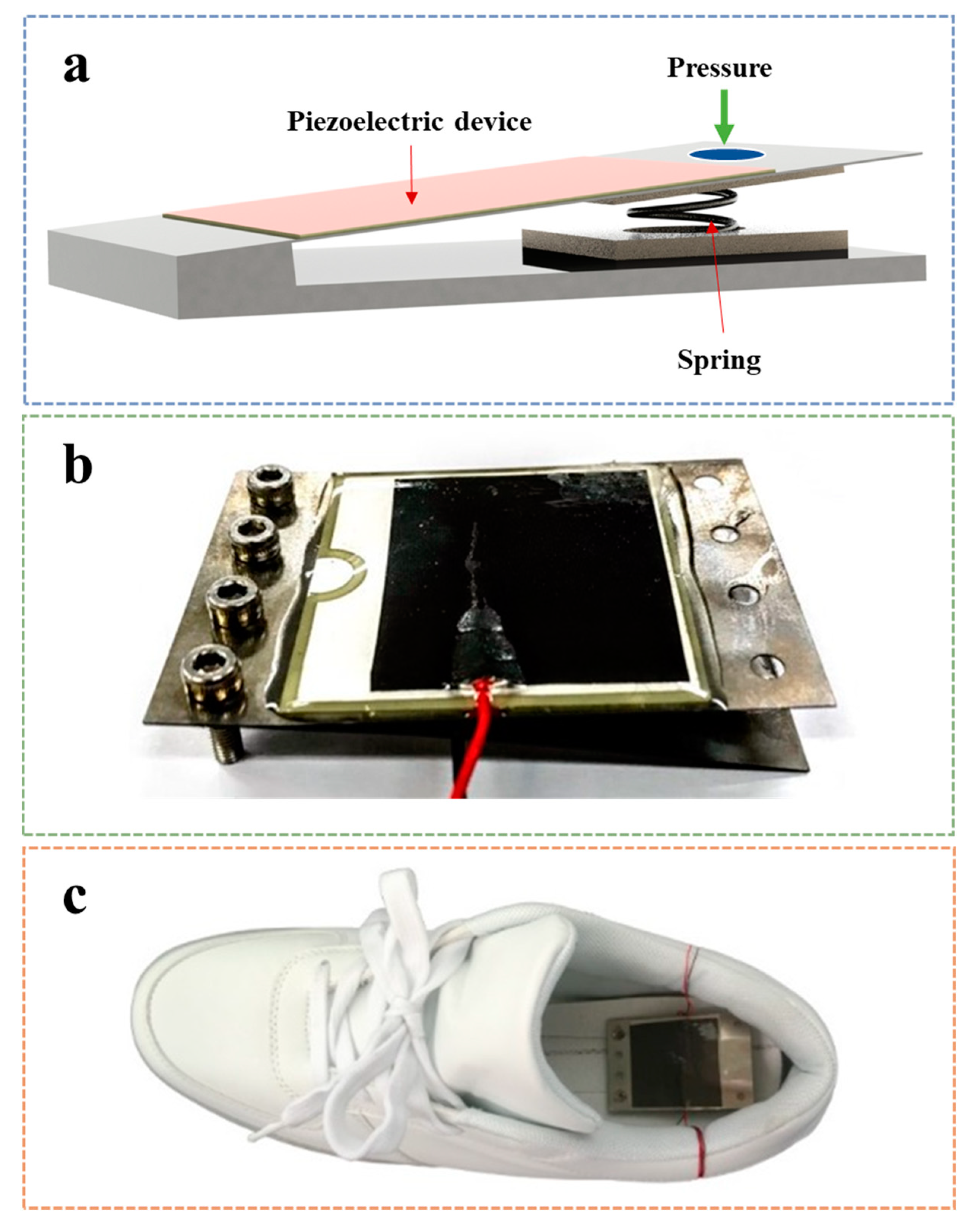
2. Design of a Piezoelectric Energy Harvester for a Shoe

2.1. UV Coating

This piezoelectric device consists of a PZT ceramic over a substrate plate of stainless steel (304SS). Table 1 lists the material properties of the piezoelectric device. The PZT ceramic can be broken or cracked under the force of a sudden impact or critical displacement, as shown in Figure 2a. Consequently, cracks in the PZT ceramic lead to a decrease in energy generation. To address this problem, first, the surface of the PZT ceramic was covered with a flexible conductive tape as an assistive electrode layer. This electrode minimizes losses in the harvested energy by connecting the individual pieces if the PZT ceramic breaks. Second, UV resin (FA-5, CHEMITECH Industry) was deposited on the ceramic to improve its structural durability to allow it to withstand better the pressure applied from the user’s weight. The resin was cured with a UV-wavelength lamp (ELC-4001, Electro-Lite Inc., Bethel, CT, USA), as shown in Figure 2b. This method is detailed in a report by Hong et al. [32]. The four layers of the piezoelectric device with UV coating are shown in Figure 2c.

2.2. Characteristic of PZT Ceramic

The PZT ceramic (of a perovskite unit with Pb2+, O2-, Ti4+, or Zr4+) generates electrical potential by converting applied mechanical stress. The piezoelectric ceramic cannot generate electrical potential (Figure 2d(i)) without mechanical stress. Conversely, when a stress is applied from the outside, the piezoelectric ceramic creates an electric potential with a polarity that changes according to whether the ceramic is being compressed (Figure 2d(ii)) or released (Figure 2d(iii)).

2.3. Piezoelectric Energy Harvester

Figure 3a,b shows a schematic and real image of the PEH with a unimorph piezoelectric device having UV coating and flexible conductive tape. This piezoelectric device is fixed on a base with rivets on one side, and a spring is inserted between the piezoelectric device and the base. The advantage of this structure is the second generation effect. The first generation effect occurs when the PEH is pushed. During this period, the spring is compressed. Alternatively, the second generation effect occurs during the recovery period of the spring. In addition, the PEH does not cause any inconvenience to the user as it requires little volume in the shoe because of the simple structure of the PEH (compressed height 2 mm, released height 7.5 mm). The PEH is fixed with rivets on the inner bottom of the shoe and is covered by an insole. The PEH is located in the heel, as shown in Figure 3c.

3. Results and Discussion

3.1. Simulation

To carry out numerical simulation of the voltage output of a piezoelectric device under applied force, COMSOL multi-physics software was used, which is based on finite element modeling. The piezoelectric-solid interaction module of COMSOL was used for this purpose. For a linear piezoelectric material, the electromechanical equations in matrix form can be written as (IEEE Standard on Piezoelectricity, ANSI Standard 176-1987):
[ S D ] = [ s E d d t ε T ] [ T E ]
where sE is the fourth-order strain components at a constant electrical field. The term εT is the second-order dielectric constant tensor at constant mechanical strain. The third-order tensor of piezoelectric coefficients is expressed by the term d. The term T and S represents a second-order stress tensor and strain tensor respectively, whereas D and E represent the electric displacement vector and electric field components, respectively. The purpose of the simulation was to estimate the open-circuit voltage across the piezoelectric device. This piezoelectric device has an attached cantilever (304SS), which is fixed at one end and free at the other end. In this application, the free end of the cantilever can displace up to a fixed value of displacement (~7.5 mm), as shown in Figure 4a. Due to the displacement strain developed in the piezoelectric device, the voltage shown in Figure 4b is generated.

3.2. Performance Evaluation

A subject weighing 60 kg put on our energy harvesting shoes and walked at normal speed for this experiment. Figure 5a shows the open-circuit voltage generated by the PEH, which shows good agreement with numerical study results shown in Figure 4b. Because the PEH is located inside the shoe, it must be able to withstand the weight of the human body; therefore, the durability of the PEH had to be evaluated. Durability testing was carried out using a pushing tester (Figure 5b) to describe the force exerted when the subject walks in the shoes with the PEH inserted under the insole. The same force was applied repetitively to the PEH using the pushing tester. The waveform of the open-circuit voltage was measured for given numbers of bendings (20 k, 40 k, and 60 k times), as shown in Figure 5c. The initial open-circuit voltage of the PEH was 60 V, which dropped to 57.2 V after 60,000 cycles (full compression and release). Thus, the voltage of the PEH dropped by 0.78% every 10,000 cycles. The resistive matching point of the PEH in the shoe was measured. The highest power was measured while increasing the variable resistance; a value of 52 μW was obtained at 280 kΩ (see graph in Figure 5d,e).

3.3. Performance According to Weight

The difference in voltage generated when subjects weighing 60–90 kg walked at normal speed with the energy harvesting shoes was measured. In Figure 6a, as the subject weight increases, it can be seen that the force applied to the PEH inside the shoe (and the magnitude of the voltage) also increases. The maximum voltage is about 22 V for 60 kg, and 90 kg generates a maximum voltage of 34 V (Figure 6b). Figure 6c,d show the changes in voltage in a capacitor (47 μF, 94 μF) when the PEH is pressed 10 times according to four weights. As the capacity of the capacitor increases, more force is required until the charged voltage reaches a specific level. Therefore, the capacitor should be selected in consideration of the operating voltage of the related electronic device and the amount of energy required to operate it.

4. Application

4.1. Step-down Converter with a Wireless Transmitter

The energy generated by the PEH is used to power a wireless transmitter. The amount of energy generated with one cycle (compress-release) by the PEH is insufficient to operate the wireless transmitter. Therefore, a specific circuit is required to store enough energy in a capacitor to operate the wireless transmitter, and then transfer power from the capacitor to the wireless transmitter when enough energy has been gathered to operate it. Figure 7 shows a schematic of the wireless communication system consisting of a rectifier, a step-down converter with under-voltage lockout (UVLO) function, and a wireless transmitter (AK-J027, Shenzhen Century Aoke Electronics Co., Ltd., Shenzhen, China). The voltage generated by the piezoelectric device is rectified through a rectifier and the energy generated is accumulated in the capacitor (Ci). Initially, the UVLO function turns the device into shutdown mode, and no current flows into the load, and energy is continuously charged to Ci. When the voltage of Ci rises and reaches the V ( I N _ s t a r t u p ) level, the circuit becomes active and the current charged in Ci flows to the load. When the voltage of Ci falls below the V ( I N _ s t o p ) level, the circuit returns the device to shutdown mode again. In this way, it is possible to periodically operate the wireless transmitter by serially collecting sufficient power. In this circuit, the voltages V ( I N _ s t a r t u p ) and V ( I N _ s t o p ) were set to 6 and 4 V, respectively, and the output voltage was 3 V. After 24 steps, the capacitor is charged with enough energy to send a signal to the receiver, as shown in Figure 8, and the transmitter run time is 60 ms (Figure 8b). After starting the device once, it is possible to operate the wireless transmitter again after 8 steps.

4.2. Emergency Monitoring

The transmitter (Figure 9a) and receiver (Figure 9b) of the wireless communication system were used for emergencies. When the user walks, the transmitter periodically sends a signal to a receiver and this signal is used to reset the timer in the receiver. If the reset signal is received before the time set by an administrator, a stable status will be displayed continuously on the screen (Figure 9d), indicating that the user is moving and working in the workplace. On the other hand, if a certain time passes without receiving the reset signal from the transmitter, a warning message is displayed on the screen (Figure 9e) to inform the administrator that user movement has stopped. A diagram of the operating sequence of the system is shown in (Figure 9c).

5. Conclusions

Most of the PEH causes a lot of inconvenience to a user due to its volume, so it was not easy to apply to the actual environment. In this paper, we focused on the development of the PEH that can be applied to the actual environment. The structure of the PEH was designed using only one spring, and since the PEH has a height of 2 mm (compressed), it does not cause inconvenience to a user even when it is applied to a shoe. In addition to the volume of the PEH, the durability of PZT has to be strengthened. The PZT can be damaged by strong external shocks because it is brittle material, so conductive tape and UV coating were applied to a piezoelectric device to improve its durability. The PEH was evaluated for durability through a pushing tester and the output was reduced by 0.78% after every 10,000 cycles of testing and generated 52 μW with one step. The energy generated by the PEH is used to operate a wireless transmitter. The power generated with eight steps is sufficient to drive it.
The PEH is embedded in the sole of a shoe and generates electricity in response to user movements. The electrical energy accumulated is then used to power a wireless communication system as a self-powered wearable device. If the user continues to move, the wireless transmitter is driven by power generated from the PEH by transmitting a periodic signal to the receiver in a control center. Conversely, if the user is in an accident, and there is no user movement, the PEH will not generate power or run the wireless transmitter. If the receiver does not receive a worker’s signal for more than a certain period of time, it is judged to be a dangerous situation and informs the administrator of the risk. This is a system that is directly related to the safety of at-risk workers, so the scope of its application is endless.

Author Contributions

Methodology, D.H.J.; formal analysis, J.H.A.; resources, S.D.H. and J.Y.C.; data curation, A.K.; writing—original draft preparation, S.Y.J., L.L.X. and C.H.R.; writing—review and editing, Y.H.J. and I.W.J.; supervision, W.S.H. and T.H.S. All authors have read and agreed to the published version of the manuscript.

Funding

This research received no external funding.

Institutional Review Board Statement

The study was conducted in accordance with the Declaration of Helsinki, and approved by the Institutional Review Board of Hanyang University, protocol code HYU-2019-12-007-3 (2020.02.26).

Informed Consent Statement

Informed consent was obtained from all subjects involved in the study.

Data Availability Statement

Not applicable.

Acknowledgments

This work was supported by the “Human Resources Program in Energy Technology” of the Korea Institute of Energy Technology Evaluation and Planning (KETEP), granted financial resources from the Ministry of Trade, Industry & Energy, Korea. (No. 20204010600090).

Conflicts of Interest

The authors declare no conflict of interest.

References

  1. Rible, G.S.; Sabate, M.C.I.; Hora, J.A. Low power design of MPPT circuit using power down system in 65nm CMOS process. J. Telecommun. Electron. Comput. Eng. 2018, 10, 45–50. [Google Scholar]
  2. Jiang, B.; Cao, K.; Chen, L.; Chen, H.; Zhang, H.; Wang, Q. Low-power design of a self-powered piezoelectric energy harvesting system. In Proceedings of the 33rd Chinese Control Conference, Nanjing, China, 28–30 July 2014; pp. 6937–6940. [Google Scholar] [CrossRef]
  3. Cheng, X.; Zhang, Y.; Xie, G.; Yang, Y.; Zhang, Z. An ultra-low power output capacitor-less low-dropout regulator with slew-rate-enhanced circuit. J. Semicond. 2018, 39, 035002. [Google Scholar] [CrossRef]
  4. Harb, A. Energy harvesting: State-of-the-art. Renew. Energy 2011, 36, 2641–2654. [Google Scholar] [CrossRef]
  5. Jung, H.J.; Song, Y.; Hong, S.K.; Yang, C.H.; Hwang, S.J.; Jeong, S.Y.; Sung, T.H. Design and optimization of piezoelectric impact-based micro wind energy harvester for wireless sensor network. Sens. Actuators A Phys. 2015, 222, 314–321. [Google Scholar] [CrossRef]
  6. Cho, J.Y.; Jeong, S.; Jabbar, H.; Song, Y.; Ahn, J.H.; Kim, J.H.; Jung, H.J.; Yoo, H.H.; Sung, T.H. Piezoelectric energy harvesting system with magnetic pendulum movement for self-powered safety sensor of trains. Sens. Actuators A Phys. 2016, 250, 210–218. [Google Scholar] [CrossRef]
  7. Jeong, S.Y.; Jung, H.J.; Jabbar, H.; Hong, S.K.; Ahn, J.H.; Sung, T.H. Design of a multi-array piezoelectric energy harvester for a wireless switch. Int. J. Hydrog. Energy 2016, 41, 12696–12703. [Google Scholar] [CrossRef]
  8. Jabbar, H.; Hong, S.D.; Hong, S.K.; Yang, C.H.; Jeong, S.Y.; Sung, T.H. Sustainable micro-power circuit for piezoelectric energy harvesting tile. Integr. Ferroelectr. 2017, 183, 193–209. [Google Scholar] [CrossRef]
  9. Wu, X.; Lee, D.-W. An electromagnetic energy harvesting device based on high efficiency windmill structure for wireless forest fire monitoring application. Sens. Actuators A Phys. 2014, 219, 73–79. [Google Scholar] [CrossRef]
  10. Wu, Y.; Hu, Y.; Huang, Z.; Lee, C.; Wang, F. Electret-material enhanced triboelectric energy harvesting from air flow for self-powered wireless temperature sensor network. Sens. Actuators A Phys. 2018, 271, 364–372. [Google Scholar] [CrossRef]
  11. Seung, W.; Gupta, M.K.; Lee, K.Y.; Shin, K.; Lee, J.; Kim, T.Y.; Kim, S.; Lin, J.; Kim, J.H.; Kim, S. Nanopatterned Textile-Based Wearable Triboelectric Nanogenerator. ACS Nano 2015, 9, 3501–3509. [Google Scholar] [CrossRef]
  12. Lee, J.H.; Hinchet, R.; Kim, S.K.; Kim, S.; Kim, S.W. Shape memory polymer-based self-healing triboelectric nanogenerator. Energy Environ. Sci. 2015, 8, 3605–3613. [Google Scholar] [CrossRef]
  13. Wang, C.; Li, J.; Yang, Y.; Ye, F. Combining Solar Energy Harvesting with Wireless Charging for Hybrid Wireless Sensor Networks. IEEE Trans. Mob. Comput. 2018, 17, 560–576. [Google Scholar] [CrossRef]
  14. Brogan, Q.; O’Connor, T.; Ha, D.S. Solar and thermal energy harvesting with a wearable jacket. In Proceedings of the 2014 IEEE International Symposium on Circuits and Systems (ISCAS), Melbourne, Australia, 1–5 June 2014; pp. 1412–1415. [Google Scholar] [CrossRef]
  15. Farhat, M.; Barambones, O.; Sbita, L. A new maximum power point method based on a sliding mode approach for solar energy harvesting. Appl. Energy 2017, 185, 1185–1198. [Google Scholar] [CrossRef]
  16. Uchino, K.; Ishii, T. Energy flow analysis in piezoelectric energy harvesting systems. Ferroelectrics 2010, 400, 305–320. [Google Scholar] [CrossRef]
  17. Pillatsch, P.; Xiao, B.L.; Shashoua, N.; Gramling, H.M.; Yeatman, E.M.; Wright, P.K. Degradation of bimorph piezoelectric bending beams in energy harvesting applications. Smart Mater. Struct. 2017, 26, 35046. [Google Scholar] [CrossRef]
  18. Asthana, P.; Khanna, G. An autonomous piezoelectric energy harvesting system for smart sensor nodes in IoT applications. Appl. Phys. A Mater. Sci. Process. 2021, 127, 1–11. [Google Scholar] [CrossRef]
  19. Rubes, O.; Chalupa, J.; Ksica, F.; Hadas, Z. Development and experimental validation of self-powered wireless vibration sensor node using vibration energy harvester. Mech. Syst. Signal. Process. 2021, 160, 107890. [Google Scholar] [CrossRef]
  20. Kim, J.H.; Cho, J.Y.; Jhun, J.P.; Song, G.J.; Eom, J.H.; Jeong, S.; Hwang, W.; Woo, M.S.; Sung, T.H. Development of a hybrid type smart pen piezoelectric energy harvester for an IoT platform. Energy 2021, 222, 119845. [Google Scholar] [CrossRef]
  21. Liu, Y.; Khanbareh, H.; Halim, M.A.; Feeney, A.; Zhang, X.; Heidari, H.; Ghannam, R. Piezoelectric energy harvesting for self-powered wearable upper limb applications. Nano Sel. 2021, 1–21. [Google Scholar] [CrossRef]
  22. Gatto, A.; Frontoni, E. Energy Harvesting system for smart shoes. In Proceedings of the 2014 IEEE/ASME 10th International Conference on Mechatronic and Embedded Systems and Applications (MESA), Senigallia, Italy, 10–12 September 2014. [Google Scholar] [CrossRef]
  23. Moro, L.; Benasciutti, D. Harvested power and sensitivity analysis of vibrating shoe-mounted piezoelectric cantilevers. Smart Mater. Struct. 2010, 19, 115011. [Google Scholar] [CrossRef]
  24. Shenck, N.S.; Paradiso, J. A Energy Scavenging With Shoe -Mounted Piezoelectrics Electricity From the Forces Exerted on a Shoe During Walking. Media 2001, 21, 30–42. [Google Scholar]
  25. Saha, P.; Goswami, S.; Chakrabarty, S.; Sarkar, S. Simulation and model verification of shoe embedded piezoelectric energy harvester. In Proceedings of the 2014 6th IEEE Power India International Conference (PIICON), Delhi, India, 5–7 December 2014; pp. 1–6. [Google Scholar]
  26. Jeong, S.Y.; Hwang, W.S.; Cho, J.Y.; Jeong, J.C.; Ahn, J.H.; Kim, K.B.; Hong, S.D.; Song, G.J.; Jeon, D.H.; Sung, T.H. Piezoelectric device operating as sensor and harvester to drive switching circuit in LED shoes. Energy 2019, 177, 87–93. [Google Scholar] [CrossRef]
  27. Kuang, Y.; Daniels, A.; Zhu, M. A sandwiched piezoelectric transducer with flex end-caps for energy harvesting in large force environments. J. Phys. D Appl. Phys. 2017, 50, 345501. [Google Scholar] [CrossRef]
  28. Yin, Z.; Gao, S.; Jin, L.; Guo, S.; Wu, Q.; Li, Z. A shoe-mounted frequency up-converted piezoelectric energy harvester. Sens. Actuators A Phys. 2021, 318, 112530. [Google Scholar] [CrossRef]
  29. Asano, S.; Nishimura, S.; Ikeda, Y.; Morita, T.; Hosaka, H. Energy harvester for safety shoes using parallel piezoelectric links. Sens. Actuators A Phys. 2020, 309, 112000. [Google Scholar] [CrossRef]
  30. Chaudhary, P.; Azad, P. Energy Harvesting Using Shoe Embedded with Piezoelectric Material. J. Electron. Mater. 2020, 49, 6455–6464. [Google Scholar] [CrossRef]
  31. Han, Y.; Cao, Y.; Zhao, J.; Yin, Y.; Ye, L.; Wang, X.; You, Z. A self-powered insole for humanmotion recognition. Sensors 2016, 16, 1502. [Google Scholar] [CrossRef] [PubMed] [Green Version]
  32. Hong, S.K.; Woo, M.S.; Song, D.; Yang, C.H.; Baek, K.H.; Sung, T.H. Restoration and reinforcement method for damaged piezoelectric materials. Ferroelectrics 2013, 449, 52–61. [Google Scholar] [CrossRef]
Figure 1. Wireless communication system between worker and control center.
Energies 15 00237 g001
Figure 2. (a) Piezoelectric device with a crack, (b) Piezoelectric device with conductive tape and ultraviolet coating, (c) Layers constituting a piezoelectric device and a perovskite PZT unit cell, (d) Direction (polarity) of the voltage formed by default state (i), compression (ii) and release (iii).
Energies 15 00237 g002
Figure 3. (a) Schematic and (b) Real image of the PEH, (c) Energy harvesting shoe with PEH.
Energies 15 00237 g003
Figure 4. (a) Total displacement of the piezoelectric device in millimeters, (b) Open-circuit voltage across the piezoelectric device.
Energies 15 00237 g004
Figure 5. (a) Open-circuit voltage, (b) Number of cycles with the pushing tester, (c) Experimental setup, (d) block diagram of measurement system, (e) Graph of voltage, current, and power according to the load resistance.
Energies 15 00237 g005
Figure 6. (a) Open-circuit voltage waveform and (b) Maximum voltage according to the weight of the object, (c) Charged voltage with a capacitor with 47 μF and (d) With 94 μF.
Energies 15 00237 g006
Figure 7. Schematic of the wireless communication circuit with a step-down converter.
Energies 15 00237 g007
Figure 8. (a) Charged voltage in the capacitor and output voltage, (b) Time needed to transfer a signal.
Energies 15 00237 g008
Figure 9. (a) Transmitter, (b) Receiver of the wireless communication system, (c) Diagram of the operating algorithm of the wireless communication system. LCD screen with (d) Stable and (e) Warning conditions.
Energies 15 00237 g009
Table 1. Material and component properties.
Material/Component ParameterValue
Piezoelectric
Ceramic
Density (g/cm3)7.6
Dielectric constant εT3302300.0
Piezoelectric coefficients, d33 (10−12 mV)450.0
Elastic properties, S11E (×10−12 m2/N)13.8
Elastic properties, S12E (×10−12 m2/N)11.8
Steel SubstrateYoung’s Modulus (GPa)193.0
Density (g/cm3)8.0
SpringSpring constant (N/mm)0.941
Diameter of spring wire (mm)0.700
Outer diameter of spring (mm)10.000
Free length of spring (mm)6.000
Solid height (mm)2.800
Publisher’s Note: MDPI stays neutral with regard to jurisdictional claims in published maps and institutional affiliations.

