Article

Reduction Reactivity of Low Grade Iron Ore-Biomass Pellets for a Sustainable Ironmaking Process

by
Ariany Zulkania
1,2,
Rochmadi Rochmadi
1,
Muslikhin Hidayat
1 and
Rochim Bakti Cahyono
1,*
1
Department of Chemical Engineering, Faculty of Engineering, Gadjah Mada University, Yogyakarta 55281, Indonesia
2
Department of Chemical Engineering, Faculty of Industrial Technology, Indonesian Islamic University, Yogyakarta 55584, Indonesia
*
Author to whom correspondence should be addressed.
Energies 2022, 15(1), 137; https://doi.org/10.3390/en15010137
Submission received: 12 November 2021 / Revised: 15 December 2021 / Accepted: 20 December 2021 / Published: 25 December 2021
(This article belongs to the Topic Energy Efficiency, Environment and Health)

Abstract

:
Currently, fossil fuels are still the primary fuel source and reducing agent in the steel industries. The utilization of fossil fuels is strongly associated with CO2 emissions. Therefore, an alternative solution for green steel production is highly recommended, with the use of biomass as a source of fuel and a reducing agent. Biomass’s growth consumes carbon dioxide from the atmosphere, which may be stored for variable amounts of time (carbon dioxide removal, or CDR). The pellets used in this study were prepared from a mixture of low-grade iron ore and palm kernel shells (PKS). The reducing reactivity of the pellets was investigated by combining thermogravimetric analysis (TGA) and laboratory experiments. In the TGA, the heating changes stably from room temperature to 950 °C with 5–15 °C/min heating rate. The laboratory experiments’ temperature and heating rate variations were 600–900 °C and 10–20 °C/min, respectively. Additionally, the reduction mechanism was observed based on the X-ray diffraction analysis of the pellets and the composition of the reduced gas. The study results show that increasing the heating rate will enhance the reduction reactivity comprehensively and shorten the reduction time. The phase change of Fe2O3 → Fe3O4 → FeO → Fe increases sharply starting at 800 °C. The XRD intensities of Fe compounds at a heating rate of 20 °C/min are higher than at 10 °C/min. Analysis of the reduced gas exhibits that carbon gasification begins to enlarge at a temperature of 800 °C, thereby increasing the rate of iron ore reduction. The combination of several analyses carried out shows that the reduction reaction of the mixture iron ore-PKS pellets runs optimally at a heating rate of 20 °C/min. In this heating rate, the reduced gas contains much higher CO than at the heating rate of 10 °C/min at temperatures above 800 °C, which encourages a more significant reduction rate. In addition, the same reduction degree can be achieved in a shorter time and at a lower temperature for a heating rate of 20 °C/min compared to 10 °C/min.

1. Introduction

The ironmaking industry is one of the largest fossil fuel-consuming industries globally. Several methods are utilized in the industry, such as the blast furnace/basic oxygen furnace (BF-BOF), direct reduction/electric arc furnace (DR-EAF), smelting reduction/basic oxygen furnace (SR-BOF), and melting of scrap in an electric arc furnace (EAF) [1]. These methods use fuel and reducing agents in coal, coke [1], natural gas, or oil derived from fossil fuels [2]. Consequently, this comprises a considerable contribution to global CO2 emissions. Thus, renewable fuels utilization is an alternative way to reduce CO2 emissions. Biomass is now being heavily explored, as evidenced by multiple studies indicating that biomass can help mitigate CO2 emissions in the ironmaking process. Purwanto et al. [3] found that using charcoal obtained from oil palm empty fruit bunch for sintering low-grade iron ore potentially decreased CO2 emission in the ironmaking process. Furthermore, utilizing torrefied biomass as an ironmaking reductant has the potential to be carbon neutral due to biomass’s propensity to adsorb CO2 during its growth phase [4]. Reducing agents required in the iron ore reduction process can be met by biomass’s when thermally decomposed into carbon, CO, and H2. This is shown in several reduction studies using charcoal from sawdust, nutshell, and waste biomass [5] and raw biomass, such as pine sawdust [6,7], coconut shell waste [8], and corn straw [9]. The use of biomass in iron ore reduction provides a good interaction between iron ore and biomass. The iron ore plays a good role as a catalyst for the pyrolysis process of biomass into the volatile matter, carbon, and gas [10,11] and, simultaneously, the pyrolysis results become reducing agents that encourage reduction reaction.
Biomass may be used as a reducing agent in various methods. The chemical vapor infiltration (CVI) method utilizes volatile matter and gas from the pyrolysis of biomass to diffuse into iron ore in different chambers. This method stimulates the formation of carbon deposits, and the reduction reaction co-occurs. The CVI method directs the formation of nanoscale distances between carbon-iron ore, which causes the reduction rate to occur faster [12]. Investigation of Cahyono et al. [13] showed that using the CVI method in a sinter plant could significantly decrease coke breeze and CO2 emissions in the ironmaking sector. Another study indicated that the reduction rate of composites with the CVI method was higher than that of a mixture of dehydrated iron ore and coke [14]. Another way for obtaining carbon deposits as reducing agents is to impregnate iron ore with biomass tar and then carbonize it. This triggers a high reduction reactivity [15]. In addition, the biomass is also used as a composite mix with iron ore in the form of pellets or briquettes. Briquettes of a mixture of iron ore and pine sawdust, which reduced at a temperature of 1100 °C with a reaction time of 60 min, generated the reduced iron with Fe metal content up to 94.5% [16]. The investigation conducted by Guo et al. [17] showed that the pellet reduction rate with biomass was relatively higher than without biomass at the same temperature. This is caused by the increase in pellet porosity due to dehydrated and pyrolyzed biomass promoting a higher interfacial chemical reaction rate.
The biomass utilization as a reducing agent can be more efficient when it is upgraded to increase the calorific value and volumetric energy density, reduce ash, more accessible handling properties, and diminish moisture content. Several forms of upgraded biomass include a pellet form, charcoal, torrefied biomass, and others [1]. According to Yuan et al. [18], the metallization degree of the reduced iron ore-straw fiber pellets was slightly lower than those of the bamboo char-iron ore pellets and the charcoal-iron ore pellets at 600–800 °C. However, it will reach a comparable metallization value to the other two pellets at temperatures above 1000 °C. Meanwhile, another study showed slightly different things. The reduction process for iron ore-raw biomass mixture pellets provides a faster reduction rate at a relatively low temperature than composite pellets of iron ore-coke and iron ore-charcoal. In addition, it displays lower apparent activation energy than the other pellets [19]. Several reduction studies using iron ore-raw biomass mixture pellets have been carried out. Rashid et al. [20] used spherical pellets of iron ore-palm kernel shell mixture with a diameter 10–12 µm in their reduction study. The composition of PKS by 30% by weight at a temperature of 900 °C resulted in the majority content of reduced pellets being wustite (FeO). Furthermore, the study conducted by Huang et al. [6] used a cylindrical pellet mixture of iron ore-pine sawdust with a Ø 15 mm × 10 mm. The study results demonstrate that the iron ore-biomass ratio that gives the optimum degree of metallization is 1:0.6.
One of the essential parameters considered in the reduction or pyrolysis process is the heating rate. Several studies have analyzed the effect of heating rate changes on reduction reactivity through thermogravimetric analysis (TGA). The study utilized carbonized goethite ore samples [12] and iron ore-biochar pellets [21]. These studies show that increasing the heating rate on the same reducing agent will shift the initial temperature of the weight loss. However, the trend of decreasing weight loss for each heating is almost the same. Eventually, several previous studies that used biomass as a reducing agent in the iron ore-biomass pellets found it attractive to apply these for manufacturing sponge iron or direct reduction iron (DRI). Based on the analysis of Mousa et al. [1] and Suopajärvi et al. [2], one of the processes in ironmaking is with DR-EAF, which requires the supply of DRI in the process. The DRI of this iron ore-biomass pellet reduction process can be an attractive alternative.
The current study is proposed due to the promising prospects for DRI preparation in the pellets of mixture iron ore-biomass and the lack of information about the effect of the heating rate on the reduction reactivity of iron ore-biomass pellets. The purpose of this study is to find out in more detail how the reduction reactivity in pellets of low degree iron ore and palm kernel shell (PKS) mixtures at various heating rates, the mechanism of the reduction of the pellets at various temperatures and heating rates, and the effect of the temperature and heating rate on the value of the reduction and metallization degrees. Results of the thermogravimetric analysis (TGA) could inform the reduction reactivity of iron ore-PKS composites at various heating rates. The temperature and heating rate were varied during the reduction laboratory experiments. The reduction mechanism was investigated from the X-ray diffraction (XRD) analysis of the reduced composites and the composition of the reduced gas. Finally, the reduced product’s degrees of reduction and metallization of the reduced product are determined.

2. Materials and Methods

2.1. Materials Specification and Preparation

PT. Meratus Jaya Iron&Steel, South Kalimantan, Indonesia, supplied raw iron ore, with a size ranging from 1 to 3 cm. Meanwhile, palm kernel shell (PKS) as the biomass utilized in the study was provided by PT. Astra Agro Lestari Tbk., South Kalimantan, Indonesia. The iron ore was finely crushed and filtered into particle sizes ranging from 53 to 149 microns. The original ore was calcined at 350 °C for 3 h in an air environment with a heating rate of 3.5 °C/min before being mixed with biomass. The heating process is designed to reduce the combined water (CW) and increase the sample surface area [9,10,11,22]. Additionally, biomass powder is obtained by crushing and sifting into particles with sizing of 74 to 149 µm. Eventually, molasses is used as a binder to form iron ore-biomass pellets.
Table 1 shows the composition and phase identification of the original iron ore/goethite as determined by X-ray fluorescence (XRF Epsilon 4, Malvern, UK) and X-ray diffraction (XRD-Bruker D2 Phaser, Billerica, MA, USA).
Phase identification of the dehydrated ore was also carried out by XRD analysis. N2 adsorption-desorption measurements were used to determine the iron ore samples’ BET surface area, pore-volume, and pore distribution (Quantachrome Instr. Ver. 10.01, Boynton Beach, FL, USA). Furthermore, scanning electron microscopy (SEM) was used to examine the surface structure of original and dehydrated iron ores (SEM-Jeol Jsm 6510 La, Tokyo, Japan). The reduction reactivity of dehydrated iron ore as a raw material for pellets was examined by thermogravimetric analysis (TG-Linseis STA, Selb, Germany). Additionally, components and elements of biomass and molasses were determined using the proximate analysis (Nabertherm N3/R Muffle furnace, Lilienthal, Germany; Heraeus UT 5042 EK, Burladingen, Germany) and ultimate analysis (LECO CHN/S-628/632, St. Joseph, MI, USA). The analysis results are provided in Table 2.
The iron ore-biomass pellet composite is formed with an iron ore-biomass ratio of 7:3 by mass, and the binder used is 9% of the mixture. After mixed ingredients are obtained, pellets for thermogravimetric analysis (TGA) and reduction experiments are formed according to the cylinder diameter and pellet weight required. The pellets for TGA analysis are thin cylindrical pellets with a diameter of 2 mm and a composite weight of 19 mg. Pellet formation utilizes a pellet mold and a pressure of 2 kN (hydraulic pump). At the same time, the formation of cylindrical pellets for the reduction experiments uses a pellet mold with a diameter of 5 mm and a pressure of 40 kN, with a pellet weight of 0.2 g. Subsequently, they are dried in an oven at 105 °C for 3 h to expel moisture before being stored in closed storage before use.

2.2. Experimental Methods

2.2.1. Thermal Analysis

Thermal analysis of the pellets of a mixture of iron ore and biomass was carried out using thermogravimetry analysis (TG-Linseis STA, Selb, Germany). The TGA results were then used to determine the reduction reactivity of the pellets. The TGA test is executed under non-isothermal conditions from room temperature to 950 °C, with 5, 10, and 15 °C/min heating rates under N2 gas flow.

2.2.2. Experiments on Reduction of Iron Ore-Biomass Pellets

The reduction experiments of the iron ore-biomass pellet are conducted by utilizing the apparatus, as shown in Figure 1. As a whole, the system for the lab-scale reduction process consists mainly of an electric furnace, a reduction chamber, temperature control, gas flow control, cooling circuit, effluent gas treatment, and a gas analyzer.
The experiment was started by inserting pellet samples weighing 16.6 g into a tubular fixed-bed reactor with a length of 20 cm and an internal diameter of 3 cm, enclosed by the furnace. After the series of cooling devices, the gas treatment, and the gas analyzer were prepared, and N2 was flowed at 200 mL/min to ensure that oxygen was expelled from the reactor. After approximately 3 min of N2 flow, heating began to be adjusted with a specific heating rate and reduction temperature. Temperature and heating rate variations are 600–900 °C and 10, 15, and 20 °C/min, respectively. After reaching the desired temperature, the reduction was carried out under isothermal conditions for 60 min. The N2 flow was halted once the reactor had cooled to room temperature to avoid product re-oxidation [17]. The reduced gas from the beginning of increasing temperature until the end of the 60th minute of the reduction process was evaluated using the gas analyzer. Furthermore, the reduced pellets were weighed and subjected to be analyzed using XRD and SEM completed with energy-dispersive X-ray spectroscopy (EDS).

2.3. Determination of Reduction and Metallization Degrees

The degree of reduction identifies how much oxygen can be released from the components contained in the sample during the reduction process. Meanwhile, the degree of metallization can inform how much the iron metal content is compared to the mass total of Fe contained in the reduced sample. The reduction degree (RD) of the reduced iron ore is determined by Equation (1) [23]:
R D = x i · R D i
where RDi is the reduction degree of each iron compound and xi is the mass fraction of each iron oxide (i represents Fe2O3, Fe3O4, FeO, or Fe). The reference intensity ratio (RIR) approach [24], which is based on the intensity of the X-ray diffracted by the component’s selected plane (hkl), is utilized to calculate the mass fraction of the iron oxide component [11,23]. Additionally, the value of the reduction degree of each iron oxide is approached by the following Equation (2) [23]:
R D X   ( % ) = ( M r   F e O 1.5 ) M r   X ( M r   F e O 1.5 ) M r   F e ·   100 %
X can be FeO1.5 (Fe2O3), FeO1.33 (Fe3O4), FeO, or Fe. The RDi value in Equation (1) is calculated using Equation (2) as RDX.
On the other hand, the metallization degree of the reduced iron ore from the reduction experiment is determined by Equation (3) [7]:
M = M F e T F e   ·   100 %
where MFe is the mass of iron metal in the reduced sample and TFe is the mass total of Fe in the reduced sample.

3. Results and Discussion

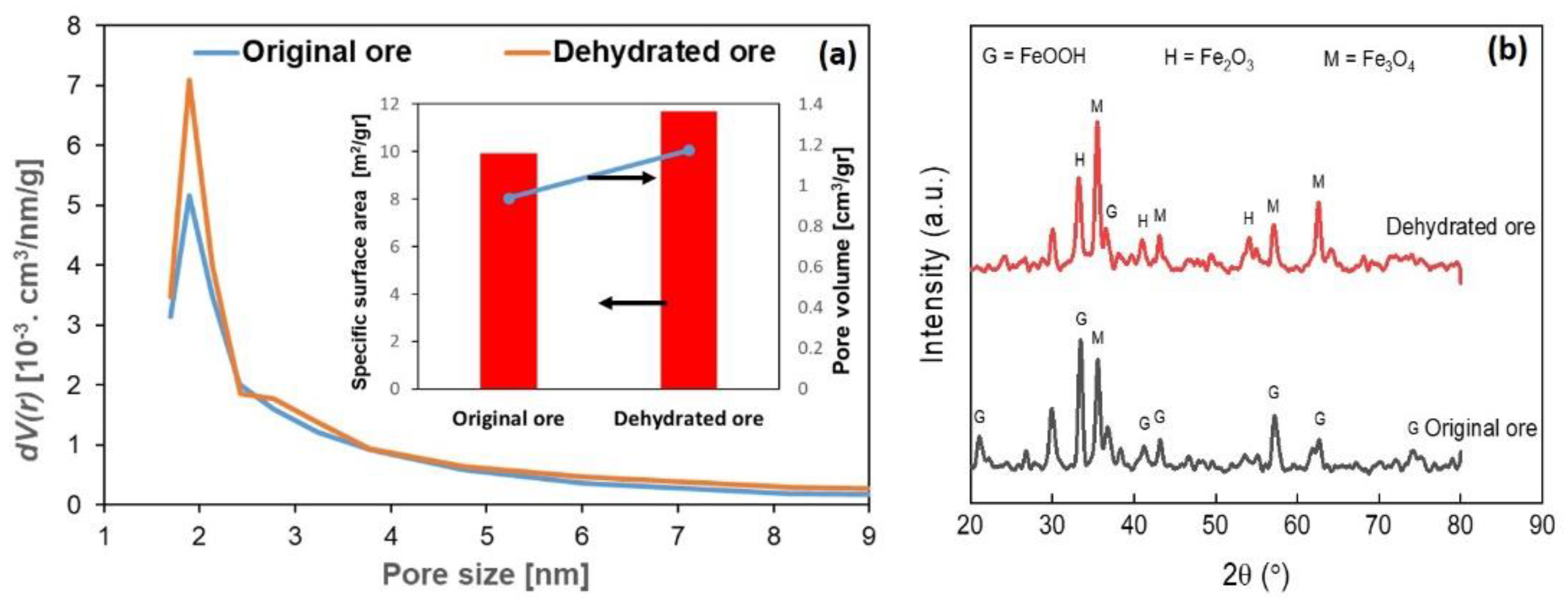
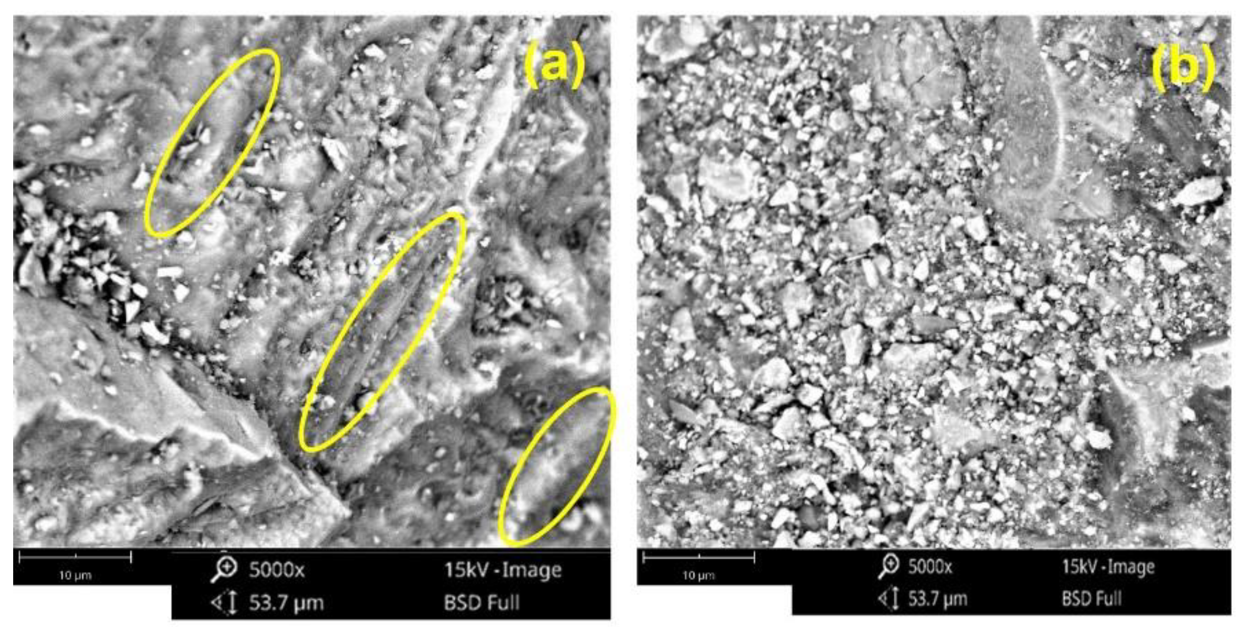
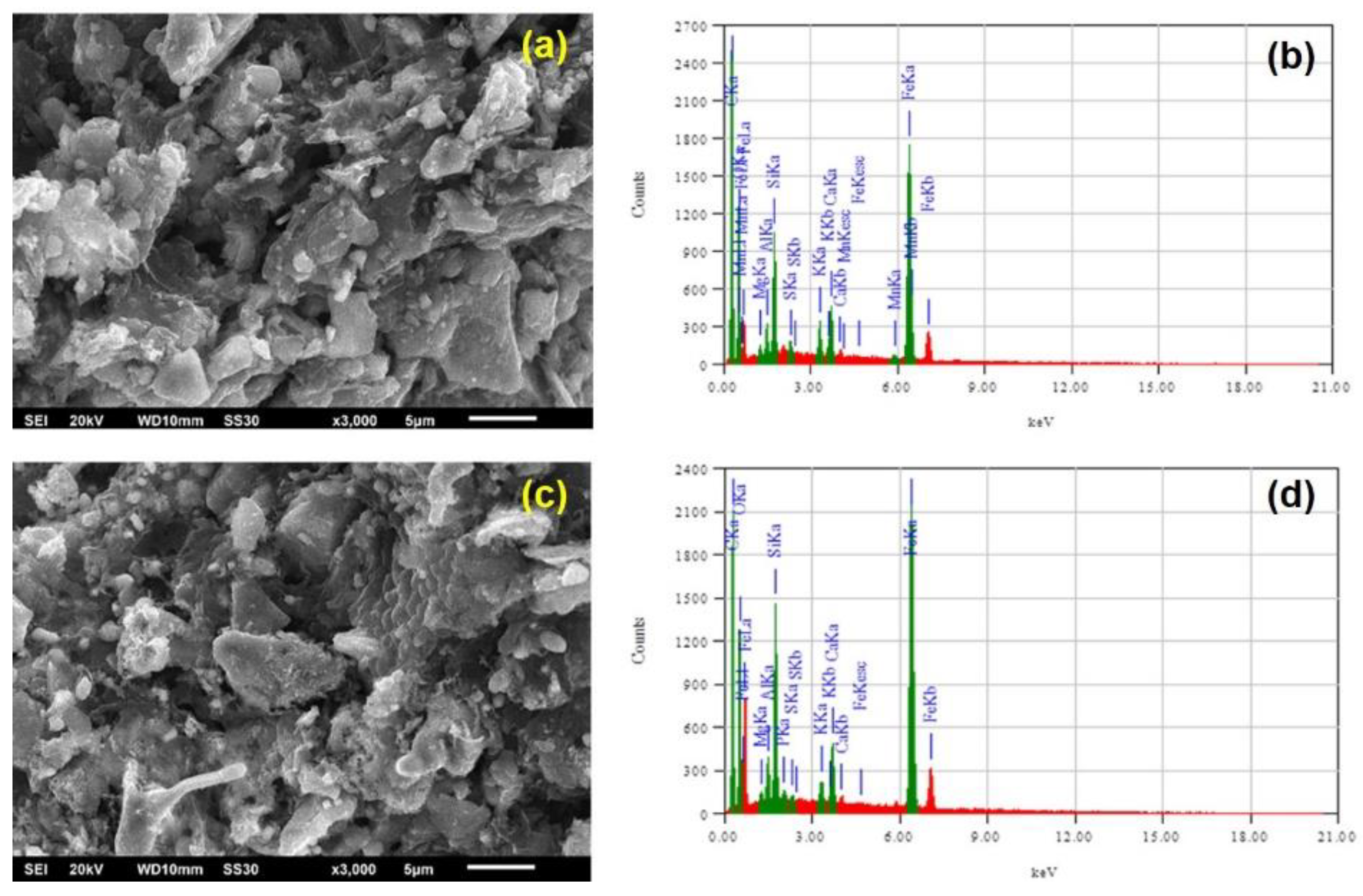
3.1. Effect of Dehydration Process on Iron Ore Properties

In the dehydration process, it is expected that the releasing water process from goethite occurred, as in Equation (4), leading to lessening the water content and enhancing the specific surface area of the iron ore [10,11,22].
2 FeOOH → Fe2O3 + H2O
Figure 2a shows the pore size distribution, BET surface area, and pore volume of the original and dehydrated ore. It seems that both ores have nanopores at around a size of 2 nm. After dehydration, the nanopores of the dehydrated ore enhance, and the mesopores at the size of 3–8 nm slightly increase. It induces the rise of the dehydrated ore’s specific surface area and pore volume.
Furthermore, X-ray diffractometry (XRD) was used to analyze the characteristic of the ore structures before and after dehydration. Figure 2b exhibits that the goethite (FeOOH) is the dominant phase in the original sample. After heating, most of FeOOH transforms to Fe2O3 and subsequently partly converts to be Fe3O4. However, the XRD peaks also indicate that a small amount of FeOOH is still comprised in the dehydrated iron. This is conformable with the research conducted by Zhao et al. [9], where FeOOH could not be fully decomposed into Fe2O3 and water after being heated at a temperature of 185–400 °C. The hydroxyl and other oxygen-containing functional groups are still present in the dehydrated ore. If they do not appear as aqueous structures of the goethite, they can be the ligand and the arrangement of oxygen and hydroxide ions in the goethite with the densest hexagonal accumulation [9].
Figure 3 reflects SEM images before and after dehydration of iron ores. From Figure 3a, the goethite is abundant in the original ore sample, as evidenced by the needle-shaped bulges [25,26] and colloform texture with cavities of goethite [8], as indicated by the yellow circle lines. The needle and colloform surfaces appear smooth, with no scratches or grooves, implying that the combined water and gangues are distributed throughout the goethite samples. Figure 3b indicates how the surface shape of iron ore altered substantially after heating. Because of the elimination of water following Equation (4) and the removal of oxygen associated with iron oxide, porous structures are apparent in the heated samples. The surface appears coarse and grainy with hexagonal and cubic geometries. It suggests the presence of iron oxides, such as hematite and magnetite, respectively [27].
The thermogravimetric analysis and the derivative curve (dm/dt) of the dehydrated ore as material for the composite pellet are represented in Figure 4. For thermogravimetric analysis, dehydrated ore pellets used molasses as a binder. The curve’s trend begins to decrease below the temperature of 150 °C, indicating an evaporation process of water content from the iron ore and the molasse (S1). It is also emphasized by a small maximum peak (dm/dt) at a temperature of 130 °C. The sharper weight loss occurred at 150–265 °C temperature (S2). As confirmed, dehydration, de-polymerization, and decomposition of biomass/molasses [10,20,28] by the presence of the second maximum peak occurred at a temperature of 200 °C.
Furthermore, at temperatures above 265 °C, the weight loss occurs more gently. There are processes of releasing volatile matter and reducing iron ore. There are many small peaks, indicating a continuous slow reduction process up to 900 °C. At temperatures of 180–450 °C, the gas-solid indirect reduction process may occur, since heating the iron ore-biomass composite pellets gradually produces reductive gases, such as CO and H2 [18]. According to Cahyono et al. [10], the reduction can commence at a temperature below 560 °C by gradually following the Fe2O3 → Fe3O4 → Fe steps. According to Zuo et al. [29], the first primary reduction reaction took place in a temperature range of 565–847 °C, which produced low valence iron oxide, such as Fe3O4, as the principal reduction product, while the CO gas produced might also contribute to Fe2O3 reduction. The reaction is as follows:
3 Fe2O3(s) + C(s) → 2 Fe3O4(s) + CO(g)

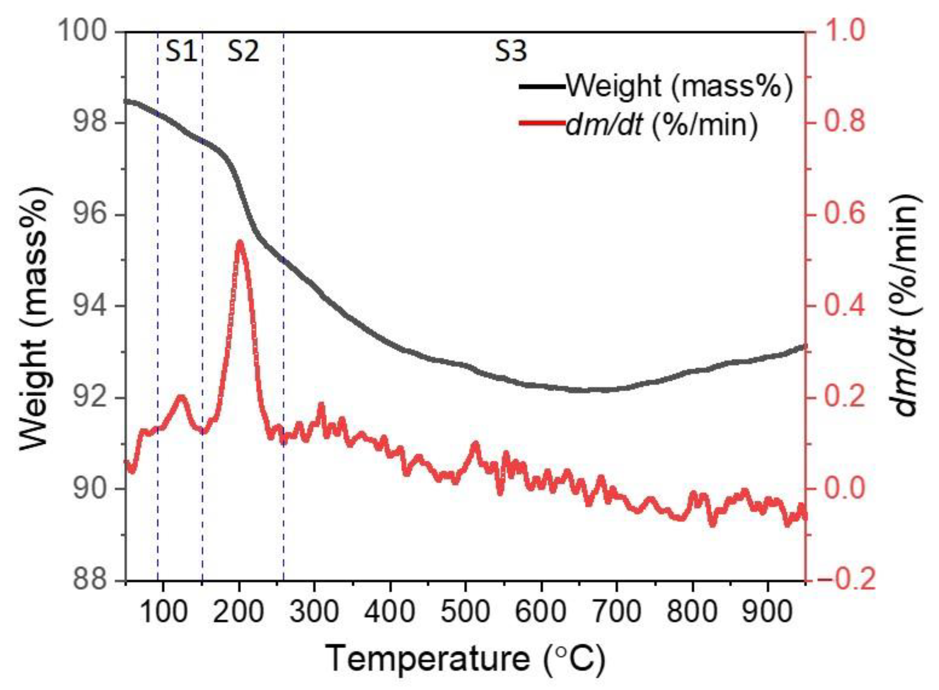
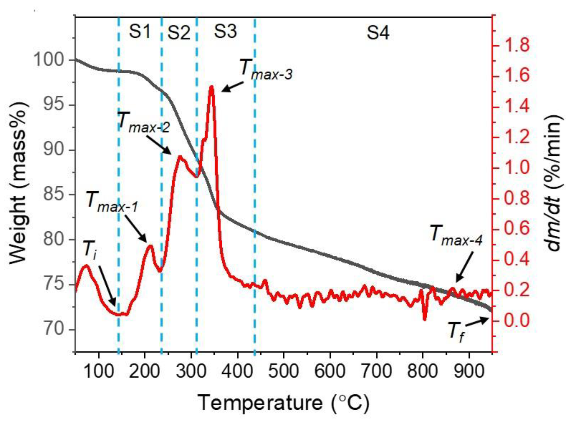
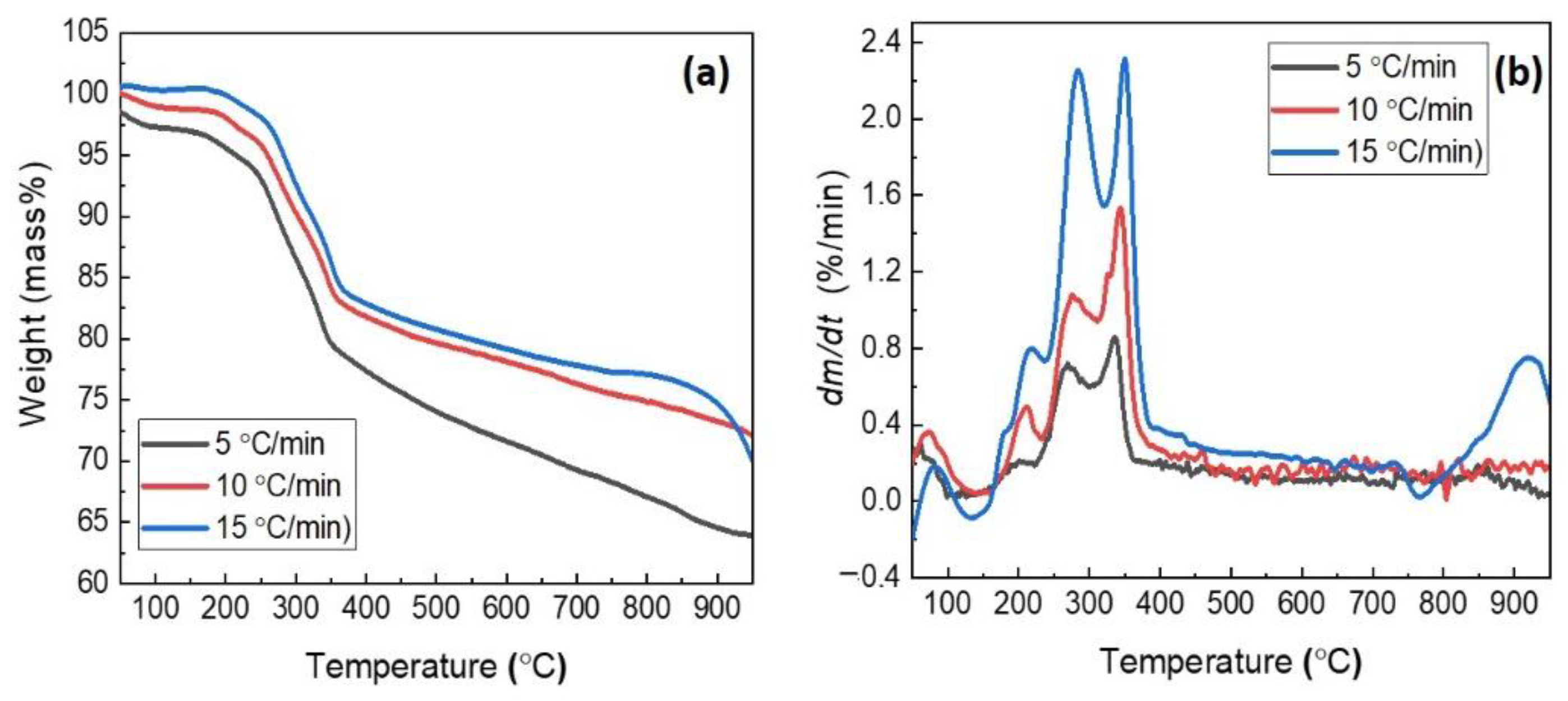
3.2. Thermogravimetric Characterization of the Composite Pellet

The thermal characteristics of the composite pellets of the iron ore and PKS mixture were analyzed using the thermogravimetric. Figure 5 shows the results of the TGA analysis of pellets with a heating rate of 10 °C/min as an example. The reduction process is divided into four stages, where stage 1 (S1) occurs at 147.32–230 °C; Stage 2 (S2) occurs at 230–315 °C; Stage 3 (S3) occurs at 315–435 °C, and Stage 4 (S4) occurs at 435–950 °C.
Some of the qualitative characterization parameters used include [21]: Ti and Tf, which are the initial temperature and the final temperature for weight loss from the reduction process, respectively; Tmax-1, Tmax-2, Tmax-3, and Tmax-4, which are the peak temperatures of the reaction rate for the four stages, respectively; dm/dtmax-1, dm/dtmax-2, dm/dtmax-3, and dm/dtmax-4, which are the peak values of the reaction rate for the four stages, respectively; tr is the reaction time from Ti to Tf; and S is the comprehensive reactivity index of the iron ore-biomass pellets, where the values are according to the following Equation (1):
S = ( d m / d t ) m e a n / ( T i 2 · T f )
where (dm/dt)mean denotes the decrease rate’s mean value.
Figure 6 presents the TGA analysis of all samples heated to a temperature of 950 °C at a heating rate of 5–15 °C/min. The samples’ weight loss and reactivity rate curves are divided into four pyrolysis/reduction temperature stages, as shown in Figure 5.
The first to third peaks appear to be partially overlapping, while the fourth peaks are small except for the heating rate of 15 °C/min. In addition, the weight loss and reaction rate curves of the composite pellets move into the high temperature zone by enhancing the heating rates (Figure 6). This phenomenon is usually named thermal hysteresis or thermal lag. It can be induced by those individual reactions that do not have enough time to complete or reach equilibrium due to the fast heating rate. Consequently, processes at higher temperatures nearby overlap each other. On the other side, there is a temperature differential through the sample’s cross-section at a high heating rate which prevents heat transfer [21]. However, the pattern of the thermal decomposition does not alter. This propensity also occurs in several studies related to pyrolysis/reduction [21,30,31].
All of the reduction characteristics described previously were computed, and the results were displayed in Table 3 to evaluate the reactivity differences of composite pellets quantitatively. From Table 3, it can be seen that the initial weight loss temperature (Ti) increases as the heating rate is increased. At same time, the total weight loss temperature (Tf) is the same at 950 °C (test temperature limit). This indicates that there is still a continuation of the reduction at temperatures above 950 °C for all samples.
Further, the peak temperatures of reaction rates (Tmax-i) and reaction rate peaks (dm/dtmax-i) for all stages exhibit ascent while raising the heating rate. In addition, the value of S, which is the thorough reduction reactivity, also increases with the rising heating rate. Otherwise, the reaction time (tr) will be shorter with an increased heating rate. The tendencies are conformable with a study conducted by Wang et al. [21]. The increase in heating rate leads the rate of volatile matter/gas release to be higher than the rate of char formation in the pyrolysis process [30,31]. The produced gases, such as CO or H2, can trigger the reduction reaction when they contact the iron ore. These cause the reactivity rate (dm/dt) to also be enhanced. Hence, the value of S also raises with the increasing heating rate. However, the analysis described previously could not explain the reduction reaction mechanism in the composite pellet sample. Therefore, the subsequent study explores the phase change and SEM analysis of the samples and analyzes the gas produced from the reduction experiments to investigate the reaction mechanism in the sample.

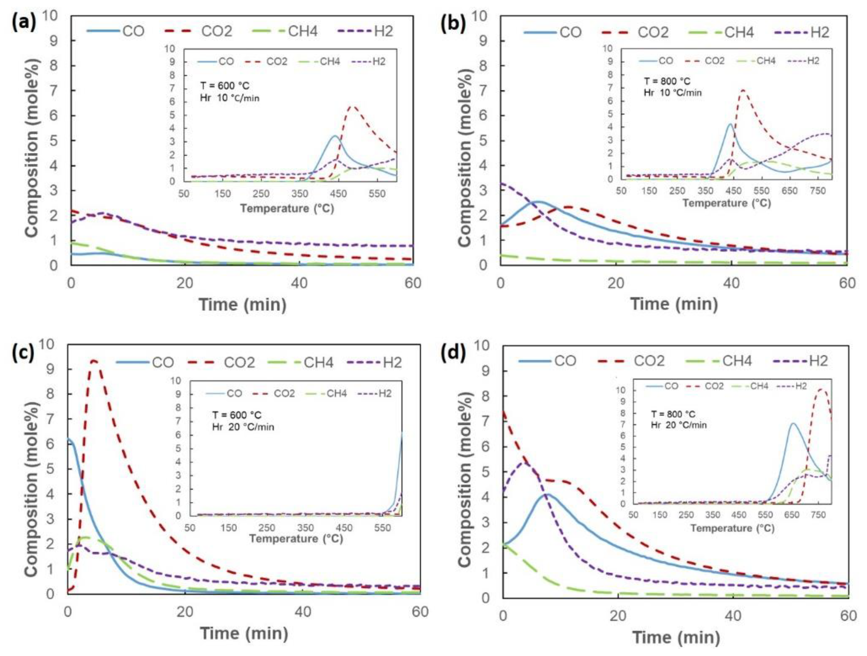
3.3. Reduction Behavior of Composite Pellet

Figure 7 shows the phase transformation of iron oxide due to temperature changes at two heating rates, namely 10 and 20 °C/min. From the two pictures, it can be noticed that the reduction process goes well as the temperature increases. At a temperature of 600–700 °C, it can be noted that the majority of the identified phases of iron compounds are magnetite (Fe3O4). In these temperatures, there has been a slow reduction reaction of Fe2O3 → Fe3O4. This is reinforced by the gradual decrease in weight loss, as illustrated in Figure 6, which reveals a reduction in reactivity. In addition, based on the XRD analysis in Figure 3b for the dehydrated ore and Figure 7, it seems that FeOOH disappears after the reduction process at 600 °C. Additionally, a part of hematite (Fe2O3) converts into magnetite. Several studies show that slow reduction has started from around 450 °C [10,18,29]. At a temperature of 800 °C, it seems that the reduction of Fe3O4 to FeO is quite significant. It is indicated by the FeO phase, which appears more in Figure 7. In addition, there is also a further reaction of FeO to Fe metal at a temperature of 850–900 °C. Starting at a temperature of 800 °C, this evidences that temperature significantly influences the reduction process, which drives the reactions of Fe2O3 → Fe3O4 → FeO → Fe reaction. At temperatures above 800 °C, carbon gasification and CO gas reduction are essential in the iron ore reduction process [10,21,29]. In addition, Yuan et al. [18] investigated that CH4, as one of the volatile matters yielded from the biomass pyrolysis process at ~900 °C, can be a reductive gas that plays a role in the following equation:
CH4 + 4 Fe2O3 → 8 Fe + 3 CO2 + 6 H2O
The trend of iron oxide phase transformation at both heating rates is similar. However, based on Figure 7, it can be seen that the FeO and Fe phases’ intensities at the heating rate of 20 °C/min are higher than the ones at the heating rate of 10 °C/min, especially at temperatures of 850–900 °C. It signifies that the presence of FeO and Fe at the heating rate of 20 °C/min is higher than the one at the heating rate of 10 °C/min. It is conformable with the analysis of the reduction characteristics from Table 3, which indicates that increasing the heating rate enhances the thorough reduction reactivity.
The temperature effect on the gas composition (CO, CO2, CH4, and H2) for the heating rates of 10 and 20 °C/min is shown in Figure 8. The graphs show the gas composition when the temperature increases (small graphs) and the isothermal reduction within 60 min for each reduction temperature. The gas profile shows that CO and H2 are produced first, followed by CO2 when the temperature rises at the same heating rate. At a heating rate of 10 and 20 °C/min, CO and H2 start appearing at a temperature of about 350 and 550 °C, respectively. Continuously, they rise to 450 and 650 °C, respectively. It can be noticed that increasing the heating rate leads to a shift in the initial temperature of the decomposition. The shift is in line with the analysis of the reduction characteristics in Section 3.2. Some studies on increasing the heating rate on the reduction reactivity of iron ore show a similar phenomenon [21,32].
As shown in Figure 8a,b for the temperature increase graph, in the temperature range of 350–450 °C, the decomposition of biomass into tar, carbon, gases, and volatile compounds occurs, followed by the release of volatile compounds and gases. CO2 gas continues to rise significantly as the temperature increases from 400 °C to 500 °C. After passing a temperature of 500 °C, it seems that the CO drops to a temperature of 700 °C (Figure S1b) while the CO2 concentration is still above the CO levels. It indicates that there is a slow reduction between CO gas and iron oxide, as shown in the following Equation:
3 Fe2O3 + CO → 2 Fe3O4 + CO2
The occurrence of the reduction reaction at temperatures below 570 °C is in accordance with several studies that have been carried out [18,29]. In addition, Zhao et al. [28] stated that carbon deposits in iron ore could induce a reduction to occur at temperatures above 500 °C. Furthermore, CO levels begin to rise above 700 °C (Figure S1b) and eventually exceed CO2 levels at temperatures above 800 °C. This denotes that the carbon gasification process of carbon obtained from the biomass pyrolysis has occurred as the following Equation:
C + CO2 → 2 CO
Additionally, when the temperature is raised to 800 or 900 °C (Figure S1d), there is a decrease in CH4 and an increase in H2. This may be due to the decomposition of CH4 into C and H2 [33]. Subsequently, the formed C can react with CO2 to generate CO according to Equation (9), and then CO reacts as shown in Equation (8).
Based on Figure 8a for the isothermal reduction step lasting 60 min, it can be seen that the presence of H2 and CO is small. This may cause the reduction to proceed slowly for the reaction of Fe2O3 → Fe3O4. The reduced iron oxide phase at temperatures of 600 and 700 °C is represented in Figure 7a. At 800 °C (Figure 8b), there is an increase in CO, indicating that the carbon gasification process is beginning to expand. This enhances the reduction rate of the Fe2O3 → Fe3O4 → FeO reactions. This occurrence corresponds to the iron oxide phase analysis in Figure 7a for a temperature of 800 °C. In addition, the reduction at a temperature of 900 °C (Figure S1d) showed that the carbon gasification process was extensive in the initial 20 min, characterized by the composition of CO, which reached 6.2% mole compared to CO2 at 3.4% mole. Although CO then reacts further with iron oxide, the composition of CO is always higher than CO2 until the end of the 60 min. It reveals that the carbon gasification rate is greater than the rate of CO reduction. On the other hand, the availability of excess CO triggers the reduction reaction rate. Based on Figure 7a, it can be seen that the intensity of Fe increases at a temperature of 900 °C, which means that the reaction of FeO → Fe is significant at this temperature.
According to Figure 8c,d for the temperature increase graph, it seems that when the temperature increases to 600 °C, the resultant gas concentration is minimal. This is due to a shift in the initial temperature of biomass decomposition from 350 °C to 550 °C at the heating rate of 10 °C/min to 20 °C/min, respectively. Therefore, biomass decomposition is continued at the start of isothermal heating at 600 °C. A temperature difference between the surface and the middle of the pellet is created by rapid heating [21]. It impacts the lack of heat transfer to the pellet center, leading to a small portion of FeOOH in the sample at a temperature of 600 °C not being dehydrated, as shown in Figure 7b. When the temperature rises to 700 °C (Figure S2b), it can be seen that CO, CO2, CH4, and H2 gases appear. This shows a process of decomposition of biomass into volatile matter and gas. Then, the temperature rising to 800 °C causes a decrease in CO and CH4 and an increase in CO2 at around 800 °C. This indicates a slow CO reduction and CH4 decomposition into C and H2. When the temperature is raised to 900 °C (Figure S2d), a similar phenomenon to the heating rate of 10 °C/min is evident. Here, the CO and H2 increase along with the decrease in CH4. This is due to an intense carbon gasification process at a temperature of 900 °C, which raises the level of CO, and subsequently reacts according to Equation (4). In addition, the increase in H2 is due to the decomposition of CH4 into C and H2 [33].
As shown in Figure 8c, where the isothermal heating lasts 60 min, CO and H2 produced by biomass decomposition have little effect on the reduction process at a temperature of 600°. This is notified by the insignificant change of the iron oxide phase from the dehydrated ore (Figure 3) to the reduced ore at this temperature (Figure 7b). At a temperature of 700 °C (Figure S2b), there seems to be an increase in H2 from the beginning, along with a decrease in CH4. This indicates the decomposition of CH4 into C and H2. The presence of H2 can influence the slow reduction that occurs. This slow reduction does not significantly change the iron oxide phase (Figure 3 and Figure 7b). Hereafter, trends occurring at temperatures of 800 and 900 °C are similar to those observed at the heating rate of 10 °C/min. Equation (5) shows that the carbon gasification process expands at 800 °C and becomes quite substantial at 900 °C (Figure S2d). At high temperatures, endothermic carbon gasification escalates, thereby producing more CO. The exothermic reaction between iron oxide and CO, occurs more quickly. It creates a coupling reaction condition between carbon gasification and reduction of iron oxide, which controls heat transfer [34].
Further, Figure 8c,d shows that the 20 °C/min heating rate produces more CO from carbon gasification than the 10 °C/min heating rate. Consequently, the reduction rate of the reaction of Fe2O3 → Fe3O4 → FeO → Fe at the heating rate of 20 °C/min becomes faster than 10 °C/min. Figure 7a,b confirm that FeO and Fe peaks are more visible and higher at the heating rate of 20 °C/min than at 10 °C/min. Applying a higher heating rate in the iron-making industry will be more advantageous because it can shorten the reduction process time. In addition, the higher heating rate can provide a higher reduction rate, and more Fe metal is produced. Furthermore, the effect of the magnitude of the reduction rate can also be influenced by H2. At temperatures above 800 °C, H2 gas can exert a more substantial reduction reaction effect than CO gas [35]. It can be seen from Figure S2d that above a temperature of 800 °C, H2 decreases slowly. According to Wei et al. [27], at a temperature of 900 °C, H2 can significantly impact the reduction reaction, but if the concentration of H2 is less than 25%, the reduction will be slow.
The results of the SEM-EDS test in Figure 9 are to see changes in the surface morphology of the reduced sample. The figure shows the difference between the reduced samples at 600 °C and 900 °C and a heating rate of 10 °C/min. From the appearance of the sample morphology, both have almost the same distribution of elements. The sample temperature of 900 °C shows a slightly higher porosity distribution, and more small basins were seen. It shows that the high temperature causes the carbon gasification process, which causes depressions to form on the surface of the reduced iron. However, in general, the final characteristics of the two reduced pellets were morphologically almost the same. This demonstrates that the temperature variation (600 and 900 °C) slightly influences the quality of the direct reduction iron product (DRI)’s surfaces but increases the pellet reduction rate, based on Figure 7 and Figure 8. Furthermore, the sample at 900 °C has a higher Fe content and a lower carbon deposit than the sample at 600 °C, according to the results of the EDS analysis (Figure 9b,d). Compared to lower temperatures (600 °C), the carbon content of biomass decomposition at 900 °C has been converted significantly through the reduction process and carbon gasification.

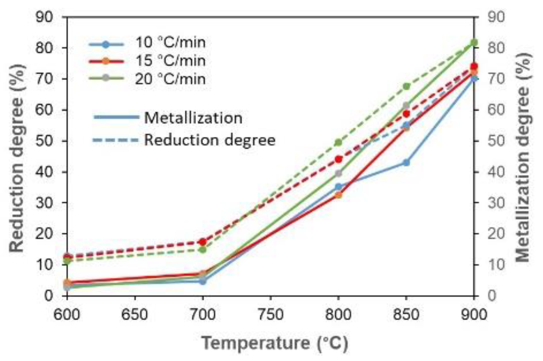
3.4. Reduction and Metallization Degree of Composite Pellet

Figure 10 shows the degrees of reduction and metallization as a temperature and heating rate function. The figure shows that the trend of the reduction and metallization degrees’ profile as a function of temperature for the three heating rates is almost the same. Increasing the temperature from 600 °C to 700 °C will cause a minimal effect on the rise of both degrees.
Meanwhile, increasing the temperature to 800 °C begins to increase the degree of reduction and metallization significantly. This corresponds to the appearance of the phase change in Figure 7, where Fe3O4 commences forming into FeO significantly at a temperature of 800 °C. At 900 °C, most of the FeO is further converted into Fe. It induces both degrees to increase significantly, from 800 °C to 900 °C. In addition, at the heating rate of 20 °C/min, both degrees showed higher values starting at 800 °C compared to heating rates of 10 and 15 °C/min. Eventually, the degree of metallization values approaches the reduction degree value at a temperature of 900 °C for all heating rates as the temperature rises.
Figure 11 exhibits the comparison between the reduction degree from the current study result and the study result of Castro et al. [36] for the case of iron ore-coke in a blast furnace. There is an increase in the reduction degree from 12.90% at 600 °C to 74.14% at 900 °C in the current study results. The presence of biomass in iron ore pellets drives an increase in the porosity of the pellet so that the reaction area between the iron ore and biomass becomes large. In addition, the high porosity produced can facilitate the entry and exit of reductant gas and reduced gas, which is beneficial for the reduction of pellets and reductant gas [17]. It seems that the reduction degree at 700 °C is almost the same for both methods at about 17.50%. However, iron ore-coke in the blast furnace demonstrates that a reduction degree of 74% is achieved at temperatures above 1000 °C. This confirms that the use of iron ore-PKS by the direct reduction method can lower the reduction temperature compared to the case of iron ore-coke in a blast furnace. Therefore, using pellets of a mixture of iron ore and biomass for manufacturing direct reduced iron (DRI) in the ironmaking industry is expected to save energy.

4. Conclusions

The conclusions of the study are summarized as follow:
  • The dehydration process of low-grade iron ore could remove water content from the iron ore powder, which had an impact through increasing the specific surface area and the occurrence of a reduction reaction that transforms Fe2O3 to Fe3O4.
  • From thermogravimetric analysis, as the heating rate rose, the initial temperature of the weight loss shifted to a higher temperature. In addition, increasing the heating rate induces elevating the comprehensive reduction reactivity index (S) and shortening the reduction time.
  • Analysis of phase transformation based on temperature changes showed that, at a temperature of 600–700 °C, most of the formed phase was magnetite (Fe3O4). By increasing the temperature to 800 °C, wustite (FeO) formation was very significant. The reduction reaction at 900 °C indicated that Fe2O3 → Fe3O4 → FeO → Fe reaction was fast. According to the reduced gas analysis, carbon gasification significantly enhanced the reduction rate starting at 800 °C. Furthermore, a heating rate of 20 °C/min resulted in higher peak Fe intensity when compared to 10 °C/min. This could be due to the carbon gasification rate at a heating rate of 20 °C/min higher than at 10 °C/min.
  • The changing trend of the reduction and metallization degrees from 600 to 700 °C was slight. However, increasing the temperature to 800 °C showed a consistently high escalation of both degrees up to 900 °C. The degrees of reduction and metallization at a heating rate of 20 °C/min showed a more considerable increase than 10 and 15 °C/min. In addition, the current study can achieve the same degree of reduction at lower temperatures compared to the iron-coke mixture in the blast furnace method. This indicates that there is energy saving in this direct reduction process.

Supplementary Materials

The following are available online at https://www.mdpi.com/article/10.3390/en15010137/s1, Figure S1: The temperature and heating rate effects on gas composition when the temperature rises (small graphs) and the isothermal reduction lasting 60 min for a heating rate of 10 °C/min (a) 600 °C; (b) 700 °C; (c) 800 °C; (d) 900 °C. Figure S2: The temperature and heating rate effects on gas composition when the temperature rises (small graphs) and the isothermal reduction lasting 60 min for a heating rate of 20 °C/min (a) 600 °C; (b) 700 °C; (c) 800 °C; (d) 900 °C.

Author Contributions

Conceptualization, M.H., R.R., R.B.C. and A.Z.; methodology, M.H., R.R., R.B.C. and A.Z.; software, M.H., R.R. and A.Z.; validation, M.H., R.R. and R.B.C.; formal analysis, R.B.C. and A.Z.; investigation, A.Z.; resources, A.Z.; data curation, A.Z.; writing—original draft preparation, A.Z.; writing—review and editing, M.H., R.R. and R.B.C.; visualization, A.Z.; supervision, M.H., R.R. and R.B.C.; project administration, A.Z.; funding acquisition, M.H. and R.B.C. All authors have read and agreed to the published version of the manuscript.

Funding

This research and the APC were funded by “Direktorat Jenderal Penguatan Riset dan Pengembangan, Kementerian Riset, Teknologi, dan Pendidikan Tinggi” with grant number: 4504/UN1/DITLIT/DIT-LIT/PT/2021.

Institutional Review Board Statement

Not applicable.

Informed Consent Statement

Not applicable.

Data Availability Statement

The data presented in this study are available on request from the corresponding author.

Acknowledgments

The author would like to thank to “Direktorat Jenderal Penguatan Riset dan Pengembangan, Kementerian Riset, Teknologi, dan Pendidikan Tinggi” for the research funding. For additional support, the following companies are acknowledged: PT. Meratus Jaya Iron&Steel, South Kalimantan, Indonesia, and PT. Astra Agro Lestari Tbk., Jakarta, Indonesia.

Conflicts of Interest

The authors declare no conflict of interest.

References

  1. Mousa, E.; Wang, C.; Riesbeck, J.; Larsson, M. Biomass applications in iron and steel industry: An overview of challenges and opportunities. Renew. Sustain. Energy Rev. 2016, 65, 1247–1266. [Google Scholar] [CrossRef]
  2. Suopajärvi, H.; Kemppainen, A.; Haapakangas, J.; Fabritius, T. Extensive review of the opportunities to use biomass-based fuels in iron and steelmaking processes. J. Clean. Prod. 2017, 148, 709–734. [Google Scholar] [CrossRef]
  3. Purwanto, H.; Zakiyuddin, A.M.; Rozhan, A.N.; Mohamad, A.S.; Salleh, H.M. Effect of charcoal derived from oil palm empty fruit bunch on the sinter characteristics of low grade iron ore. J. Clean. Prod. 2018, 200, 954–959. [Google Scholar] [CrossRef]
  4. Ubando, A.T.; Chen, W.-H.; Ong, H.C. Iron oxide reduction by graphite and torrefied biomass analyzed by TG-FTIR for mitigating CO2 emissions. Energy 2019, 180, 968–977. [Google Scholar] [CrossRef]
  5. Cheng, Z.; Yang, J.; Zhou, L.; Liu, Y.; Guo, Z.; Wang, Q. Experimental study of commercial charcoal as alternative fuel for coke breeze in iron ore sintering process. Energy Convers. Manag. 2016, 125, 254–263. [Google Scholar] [CrossRef] [Green Version]
  6. Huang, D.-B.; Zong, Y.-B.; Wei, R.; Gao, W.; Liu, X.-M. Direct Reduction of High-phosphorus Oolitic Hematite Ore Based on Biomass Pyrolysis. J. Iron Steel Res. Int. 2016, 23, 874–883. [Google Scholar] [CrossRef]
  7. Wei, R.; Cang, D.; Bai, Y.; Huang, D.; Liu, X. Reduction characteristics and kinetics of iron oxide by carbon in biomass. Ironmak. Steelmak. 2016, 43, 144–152. [Google Scholar] [CrossRef]
  8. Nayak, D.; Dash, N.; Ray, N.; Rath, S.S. Utilization of waste coconut shells in the reduction roasting of overburden from iron ore mines. Powder Technol. 2019, 353, 450–458. [Google Scholar] [CrossRef]
  9. Zhao, H.; Li, Y.; Song, Q.; Liu, S.; Ma, Q.; Ma, L.; Shu, X. Catalytic reforming of volatiles from co-pyrolysis of lignite blended with corn straw over three different structures of iron ores. J. Anal. Appl. Pyrolysis 2019, 144, 104714. [Google Scholar] [CrossRef]
  10. Cahyono, R.B.; Rozhan, A.N.; Yasuda, N.; Nomura, T.; Hosokai, S.; Kashiwaya, Y.; Akiyama, T. Catalytic coal-tar decomposition to enhance reactivity of low-grade iron ore. Fuel Process. Technol. 2013, 113, 84–89. [Google Scholar] [CrossRef]
  11. Abe, K.; Kurniawan, A.; Ohashi, K.; Nomura, T.; Akiyama, T. Ultrafast Iron-Making Method: Carbon Combustion Synthesis from Carbon-Infiltrated Goethite Ore. ACS Omega 2018, 3, 6151–6157. [Google Scholar] [CrossRef]
  12. Hosokai, S.; Matsui, K.; Okinaka, N.; Ohno, K.; Shimizu, M.; Akiyama, T. Kinetic Study on the Reduction Reaction of Biomass-Tar-Infiltrated Iron. Energy Fuels 2012, 26, 7274–7279. [Google Scholar] [CrossRef]
  13. Cahyono, R.B.; Yasuda, N.; Nomura, T.; Akiyama, T. Utilization of Low Grade Iron Ore (FeOOH) and Biomass Through Integrated Pyrolysis-tar Decomposition (CVI process) in Ironmaking Industry: Exergy Analysis and its Application. ISIJ Int. 2015, 55, 428–435. [Google Scholar] [CrossRef] [Green Version]
  14. Mochizuki, Y.; Nishio, M.; Tsubouchi, N.; Akiyama, T. Preparation of a Carbon-Containing Pellet with High Strength and High Reactivity by Vapor Deposition of Tar to a Cold-Bonded Pellet. Energy Fuels 2017, 31, 8877–8885. [Google Scholar] [CrossRef]
  15. Zulkania, A.; Rochmadi, R.; Cahyono, R.B.; Hidayat, M. Investigation into Biomass Tar-Based Carbon Deposits as Reduction Agents on Iron Ore Using the Tar Impregnation Method. Metals 2021, 11, 1623. [Google Scholar] [CrossRef]
  16. Luo, S.; Yi, C.; Zhou, Y. Direct reduction of mixed biomass-Fe2O3 briquettes using biomass-generated syngas. Renew. Energy 2011, 36, 3332–3336. [Google Scholar] [CrossRef]
  17. Guo, D.; Hu, M.; Pu, C.; Xiao, B.; Hu, Z.; Liu, S.; Zhu, X. Kinetics and mechanisms of direct reduction of iron ore-biomass composite pellets with hydrogen gas. Int. J. Hydrogen Energy. 2015, 40, 4733–4740. [Google Scholar] [CrossRef]
  18. Yuan, P.; Shen, B.; Duan, D.; Adweek, G.; Mei, X.; Lu, F. Study on the formation of direct reduced iron by using biomass as reductants of carbon-containing pellets in RHF process. Energy 2017, 141, 472–482. [Google Scholar] [CrossRef]
  19. Yuan, X.; Luo, F.; Liu, S.; Zhang, M.; Zhou, D. Comparative Study on the Kinetics of the Isothermal Reduction of Iron Ore Composite Pellets Using Coke, Charcoal, and Biomass as Reducing Agents. Metals 2021, 11, 340. [Google Scholar] [CrossRef]
  20. Rashid, R.Z.A.; Mohd-Salleh, H.; Ani, M.H.; Yunus, N.A.; Akiyama, T.; Purwanto, H. Reduction of low grade iron ore pellet using palm kernel shell. Renew. Energy 2014, 63, 617–623. [Google Scholar] [CrossRef]
  21. Wang, G.; Zhang, J.; Zhang, G.; Wang, H.; Zhao, D. Experiments and Kinetic Modeling for Reduction of Ferric Oxide-biochar Composite Pellets. ISIJ Int. 2017, 57, 1374–1383. [Google Scholar] [CrossRef] [Green Version]
  22. Saito, G.; Nomura, T.; Sakaguchi, N.; Akiyama, T. Optimization of the Dehydration Temperature of Goethite to Control Pore Morphology. ISIJ Int. 2016, 56, 1598–1605. [Google Scholar] [CrossRef] [Green Version]
  23. Kurniawan, A.; Abe, K.; Ohashi, K.; Nomura, T.; Akiyama, T. Reduction of mild-dehydrated, low-grade iron ore by ethanol. Fuel Process. Technol. 2018, 178, 156–165. [Google Scholar] [CrossRef]
  24. Hubbard, C.R.; Snyder, R.L. RIR-Measurement and Use in Quantitative XRD. Powder Diffr. 1988, 3, 74–77. [Google Scholar] [CrossRef] [Green Version]
  25. Walter, D.; Buxbaum, G.; Laqua, W. The Mechanism of the Thermal Transformation from Goethite to Hematite. J. Therm. Anal. Calorim. 2001, 63, 733–748. [Google Scholar] [CrossRef]
  26. Pradhan, N.; Nayak, R.R.; Mishra, D.K.; Priyadarshini, E.; Sukla, L.B.; Mishra, B.K. Microbial Treatment of Lateritic Ni-ore for Iron Beneficiation and Their Characterization. World Environ. 2012, 2, 110–115. [Google Scholar] [CrossRef] [Green Version]
  27. Wei, Z.; Zhang, J.; Qin, B.; Dong, Y.; Lu, Y.; Li, Y.; Hao, W.; Zhang, Y. Reduction kinetics of hematite ore fines with H2 in a rotary drum reactor. Powder Technol. 2018, 332, 18–26. [Google Scholar] [CrossRef]
  28. Zhao, H.; Li, Y.; Song, Q.; Liu, S.; Ma, L.; Shu, X. Catalytic reforming of volatiles from co-pyrolysis of lignite blended with corn straw over three iron ores: Effect of iron ore types on the product distribution, carbon-deposited iron ore reactivity and its mechanism. Fuel 2021, 286, 119398. [Google Scholar] [CrossRef]
  29. Zuo, H.-B.; Hu, Z.-W.; Zhang, J.-L.; Li, J.; Liu, Z.-J. Direct reduction of iron ore by biomass char. Int. J. Miner. Met. Mater. 2013, 20, 514–521. [Google Scholar] [CrossRef]
  30. Chen, J.; Fan, X.; Jiang, B.; Mub, L.; Yao, P.; Yin, H.; Song, X. Pyrolysis of oil-plant wastes in a TGA and a fixed-bed reactor: Thermochemical behaviors, kinetics, and products characterization. Bioresour. Technol. 2015, 192, 592–602. [Google Scholar] [CrossRef]
  31. Somerville, M.; Deev, A. The effect of heating rate, particle size and gas flow on the yield of charcoal during the pyrolysis of radiata pine wood. Renew. Energy 2020, 151, 419–425. [Google Scholar] [CrossRef]
  32. Wu, C.; Budarin, V.L.; Gronnow, M.J.; De Bruyn, M.; Onwudili, J.A.; Clark, J.H.; Williams, P.T. Conventional and microwave-assisted pyrolysis of biomass under different heating rates. J. Anal. Appl. Pyrolysis 2014, 107, 276–283. [Google Scholar] [CrossRef]
  33. Guo, D.; Li, Y.; Cui, B.; Chen, Z.; Luo, S.; Xiao, B.; Zhu, H.; Hu, M. Direct reduction of iron ore/biomass composite pellets using simulated biomass-derived syngas: Experimental analysis and kinetic modelling. Chem. Eng. J. 2017, 327, 822–830. [Google Scholar] [CrossRef]
  34. Mishra, S. Review on Reduction Kinetics of Iron Ore–Coal Composite Pellet in Alternative and Sustainable Ironmaking. J. Sustain. Metall. 2020, 6, 541–556. [Google Scholar] [CrossRef]
  35. Oh, J.; Noh, D. The reduction kinetics of hematite particles in H2 and CO atmospheres. Fuel 2017, 196, 144–153. [Google Scholar] [CrossRef]
  36. Castro, J.A.; Nogami, H.; Yagi, J. Transient Mathematical Model of Blast Furnace Based on Multi-fluid Concept, with Application to High PCI Operation. ISIJ Int. 2000, 40, 637–646. [Google Scholar] [CrossRef] [Green Version]
Figure 1. Scheme of apparatus for reduction experiments.
Energies 15 00137 g001
Figure 2. Alteration in (a) pore size distribution and SBET and VBJH values; (b) XRD patterns of original iron ore and dehydrated ore.
Energies 15 00137 g002
Figure 3. Images of SEM for iron ore (a) before and (b) after dehydration.
Energies 15 00137 g003
Figure 4. Weight percentage and reactivity rate curve of dehydrated iron ore at a heating rate of 10 °C/min.
Energies 15 00137 g004
Figure 5. Weight loss and reactivity rate (dm/dt) curves of the iron ore-biomass pellet at a heating rate of 10 °C/min.
Energies 15 00137 g005
Figure 6. Thermogravimetric analysis: (a) weight percentage; (b) reactivity rate curves of composite pellet at a different heating rate.
Energies 15 00137 g006
Figure 7. XRD pattern of samples after reduction process from 600–900 °C for 1 h with a heating rate of (a) 10 °C/min; (b) 20 °C/min.
Energies 15 00137 g007
Figure 8. The temperature and heating rate effects on gas composition when the temperature rises (small graphs) and the isothermal reduction lasting 60 min for a heating rate of 10 °C/min (a,b) and 20 °C/min (c,d).
Energies 15 00137 g008
Figure 9. SEM images showing a change of iron ore surface after reduction and result of EDS analysis: (a,b) at 600 °C; (c,d) at 900 °C with heating rate 10 °C/min and reduction time 60 min.
Energies 15 00137 g009
Figure 10. Reduction and metallization degrees of the iron ore-biomass pellets with temperature and heating rate variations.
Energies 15 00137 g010
Figure 11. Reduction degree of the iron ore-biomass pellets by a direct reduction process at different temperatures compared to the blast furnace process.
Energies 15 00137 g011
Table 1. Contexture of goethite ore.
CompositionTFeFe2O3SiCaAlOCWC
Weight (mass%)46.83518.9419.2255.3660.53437.4924.935.62
TFe: Total Fe; CW: combined water.
Table 2. Properties of the biomass and molasses.
SampleProximate Analysis (Mass%, Air-Dried Basis)Ultimate Analysis (Mass%, Air-Dried Basis)
Fixed CarbonVolatile
Matter
WaterAshCHONS
PKS30.77165.5792.7000.95050.7206.1700.22041.7600.030
Molasses4.96856.44135.1913.43029.6907.7300.56057.4000.260
Table 3. The distinctive reduction parameter of the composite pellet at three different heating rates.
Heating Rate (°C/min)Ti (°C)Tmax-1 (°C)Tmax-2 (°C)Tmax-3 (°C)Tmax-4 (°C)Tf (°C)dm/dtmax-1 (%/min)dm/dtmax-2 (%/min)dm/dtmax-3 (%/min)dm/dtmax-4 (%/min)dm/dtmean (%/min)Str (min)
5109.02200.57269.60336.22847.989500.210.720.860.190.171.5 × 10-8168.21
10138.00212.49276.10343.69862.939500.491.081.530.210.291.6 × 10-882.07
15147.32218.44284.05349.66920.009500.792.252.310.750.482.3 × 10-855.05
Publisher’s Note: MDPI stays neutral with regard to jurisdictional claims in published maps and institutional affiliations.

