Abstract
Heat recovery from ventilation air is proven technology resulting in significant energy savings in modern buildings. The article presents an energy analysis of an air handling unit with a cross-flow heat exchanger in an office building in Poland. Measurements were taken during one year of operation, from 1 August 15 to 31 July 16, covering both heating and cooling periods. Calculated annual temperature efficiency of heat and cold recovery amounted to 65.2% and 64.6%, respectively, compared to the value of 59.5% quoted by the manufacturer. Monthly efficiency of heat recovery was from 37.6% in August to 68.7% in November, with 63.9% on average compared to 59.5% declared by the manufacturer. Cold recovery was from 63.3% in April to 72.8% in September, with 68.1% annually. Calculated recovered heat and cold amounted 25.6 MWh and 0.26 MWh, respectively. Net energy savings varied from −0.46 kWh/m2 in August, when consumption by fans exceeded savings, to 5.60 kWh/m2 in January.
1. Introduction
Buildings in Europe are responsible for about 40% of total energy consumption [1], having significant impact on economies of European countries. This problem is also very important in Poland, where a number of efficiency-oriented initiatives in buildings have been taken recently [2,3,4]. Introduction of the Directive on the Energy performance of buildings (EPBD) has resulted in the development of the building energy certification system and new requirements for thermal protection of buildings [5]. The Regulation of the Minister of Infrastructure and Development on the methodology to determine the energy performance of a building and energy performance certificates [6] presents in detail the calculation procedure to obtain energy performance indicators: EP (nonrenewable primary energy), EK (final energy), and EU (usable energy). This procedure has been presented by several authors recently [7,8,9,10,11,12,13,14,15]. The base to obtain EP, EK, and EU is calculated annual energy use for space heating; cooling; ventilation; domestic hot water (DHW); and, in nonresidential buildings, lighting. These factors include energy directly utilized to provide a given service and consumed by an additional equipment necessary for the operation of the technical systems in the building as well.
The most significant share in energy consumption of European buildings belongs to heating and cooling [16,17]. These needs are affected by several components. One of significant importance, regardless of the energy standard of a building, is ventilation. This is the case because ventilation works continuously or, at least, during presence of people in a building, providing fresh air to the given space and at the same time removing used air for hygiene and sanitary reasons. During the heating season, outdoor air supplied to the building has lower temperature than indoor air. In the cooling period, the opposite phenomenon occurs. Hence, additional energy is needed to maintain set indoor air temperature, resulting in a significant share of energy use for ventilation purposes in buildings [18,19,20,21,22].
To reduce these heat losses, ventilation systems with heat recovery are used [23,24,25,26], usually with cross-flow, counter-current, or rotary heat exchangers [27,28]. Current Polish regulations [29] for buildings with mechanical ventilation, supply and exhaust ventilation, or air-conditioning systems with the capacity over 500 m3/h require the minimum temperature efficiency of heat recovery of 50%. Efficiency of heat recovery is commonly assumed constant throughout the year when calculating heating and cooling energy of buildings, usually on the basis of the manufacturers’ or designers’ documentation.
Wang et al. [30] presented the passive ultra-low energy office building adopting ventilation heat recovery system with rotary heat exchanger. Thermal recovery rate of more than 75% was given, but no detailed analysis was presented.
Zemitis and Borodinecs [31] compared two variants of mechanical ventilation systems—rotary and counter-flow exchangers with assumed efficiency of 85% and 88%, respectively. They also presented simulations of heating and cooling energy in a single-family building with a ventilation airflow rate of 640 m3/h and heat recovery efficiency of an air handling unit (AHU) of 85%. Simulated annual heating and cooling demand with and without heat recovery amounted to 12,643 kWh and 26,965 kWh, respectively.
Simulations of new single-family home located in Greenland in order to assess reduction of energy consumption after its modernization were presented in [32]. The input data for the model were taken from the measurements. Mechanical ventilation with rotary heat exchanger was used. Its temperature efficiency was set to 75%, although 80% was given in its technical documentation. The authors concluded that energy recovered in the heat exchanger amounted to 56 kWh/m2 on average per year being a significant part of saved energy.
Firląg [5] analyzed plus energy residential buildings’ solutions in a Polish heating-dominated climate at different thermal requirements. Balanced ventilation with annual heat recovery efficiency above 85% and 90% was analyzed, resulting in annual savings of EUR 580 in relation to the base variant with natural ventilation.
Single-family residential building was presented in [33]. Heat recovery of 55% and 86% was assumed, resulting in 71% and 63% energy savings versus base variant with gravity ventilation. Similar considerations were presented in [34,35,36,37].
Mechanical ventilation can be also connected with ground heat exchanger (GHE). In the analysis of the low energy building located in northeast and southwest Poland [38], GHE was connected to the mechanical system with 75% heat recovery. It was compared to the conventional (natural ventilation) and passive (90% of heat recovery) variants. Annual energy consumption and exploitation costs were given but impact of heat recovery was not discussed. Rabczak and Kut [39] simulated application of a UV lamp in the air duct in front of the air handling unit connected to the ground heat exchanger. Assuming an annual efficiency of heat recovery in an AHU of 0.8, they calculated energy consumption and operation costs of the ventilation system with and without ground heat exchanger. In a similar case [40], heat exchanger efficiency was assumed at 50%.
Monitoring of everyday operation of the building’s technical systems enables the user to obtain information on their actual performance. Then, calculation of energy use can be based on the data closer to the real state. This is a very important issue because the energy certificates affect the transaction prices on the retail market [41,42]. For these reasons, studies based on the measurements in real conditions are of special interest.
Borowski et al. [43] presented modernization analysis of the historical hotel to the low-energy standard. One of the proposed solutions was to install air handling units with a regenerative counterflow exchanger. Average seasonal air handling unit temperature efficiency was assumed at 45%. However, no further data related to ventilation system were provided.
In [44] an extensive analysis of a hybrid ventilation system consisting of earth to air heat exchangers, free cooling, and evaporative cooling air handling unit heat exchanger in a Near Zero Energy Building (nZEB) was presented. The authors focused on the annual costs and energy consumption analyses for different control strategies.
In [45], an evaluation of the performance of a plate-type heat exchanger tested on a laboratory bench was shown. Its construction, according to EN 308 [46], made it possible to measure flowrates, the pressure drops, and inlet/outlet temperatures. Several tests were performed. Obtained energy efficiency factor of the heat recovery system was around 90% and increased when the airflow rate decreased.
A number of similar studies performed in laboratory conditions [47,48,49] focused on different technical aspects of air handling units and heat recovery issues under selected environmental conditions. It was clear that they could not fully match real exploitation circumstances. This gap can be filled by studies based on the long-term (especially annual) analyses of the energy performance of air handling units in terms of efficiency of energy certification conducted under normal operation of buildings.
Of course, it is not always possible to measure many parameters using special equipment or an embedded system in such circumstances. However, relying on the basic measurements available to the user thanks to the control and service software of Heating, Ventilation and Air Condition (HVAC) equipment makes it possible to carry out detailed analyses relevant to the user, giving them precise image of energy and economic efficiency of the used devices.
In this paper, an annual analysis of air handling unit with cross-flow heat exchanger is presented. It focuses on temperature efficiency of heat and cold recovery, energy consumption for fans, and economic considerations. The study is based on measurements taken in a commercial office building in 2015 and 2016 during 12 months of its normal operation. Measurement data were taken from sensors mounted in the air handling unit by its manufacturer and are available for the user and service.
2. Materials and Methods
2.1. Air Handling Unit
The air handling unit with the cross-flow heat exchanger is schematically presented in Figure 1. It consists of air filters (1), exhaust fan (2), cross-flow heat exchanger (3), supply fan (4), heating coil (5), and cooling coil (6).
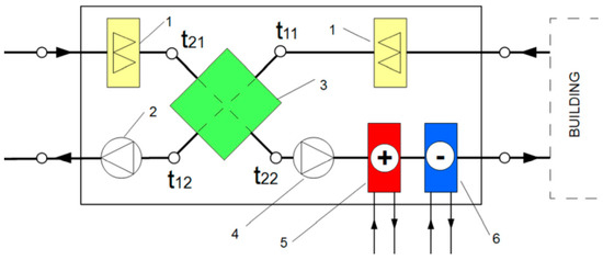
Figure 1.
Schematic view of an air handling unit with a cross-flow heat exchanger.
Temperatures in Figure 1 are assigned according to EN 308 [46,50], which specifies methods to be used for laboratory testing of air-to-air heat recovery devices in buildings to obtain rating data and verify performance data given by manufacturers.
This standard defines 2 measures of the efficiency of heat exchangers. These are the temperature ratio (also known as temperature efficiency or temperature effectiveness [51]) and humidity ratio (humidity or latent effectiveness [52]) defined at the supply side of the exchanger (indexes according to Figure 1), respectively:
Total (enthalpy [52,53]) effectiveness is also used:
Temperature effectiveness, given by Equation (1), is of special interest because it can be easily evaluated using temperature measurements (Figure 1) and is also given by manufacturers in datasheets of their equipment. In addition, in sensible heat exchangers it can be assumed that sensible and total effectiveness of heat recovery are equal [52].
In practice, temperature t22 is not always available. Instead, supply air temperature delivered to the room (t22,s) is measured. The increase of air temperature should be also taken into account as it flows through the fan, assigned t22,f-t22 (Figure 2). Then, if heating/cooling coil capacity and ventilation airflow are known [54,55]:
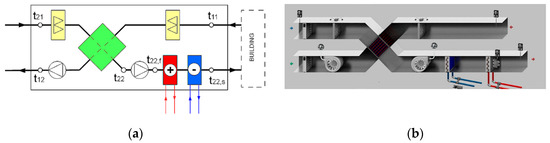
Figure 2.
(a) Schematic view of specific temperatures in the air handling unit (AHU); (b) view of the AHU in the Building Management System (BMS).
From this
Air density (ρ) and specific heat capacity (cp) at known temperature (t) can be computed from the following formulas [56,57]:
ρ = 351.99/(t + 273.15) + 344.84/(t + 273.15)2
cp = 1030.5 − 0.19975 (t + 273.15) + 3.9734 ∙ 10−4 (t + 273.15)2
Then, the t22,s should be inserted in Equation (1) instead of t22. Omitting temperature rise of air while passing filters Figure 1 can be modified into Figure 2a.
Ventilation air supplied to a building is warmed up or cooled down in the heat exchanger during heating or cooling period, respectively. This temperature change results in energy savings in the period of the length of Δτ given by
2.2. On-Site Measurements
Research was conducted in Katowice (south Poland) from 1 August 2015 to 31 July 2016, i.e., during the whole year, covering heating, cooling, and intermediate periods. External air temperature (Figure 3a) varied from −14.4 °C at 8:00 on 4 January 2016 to 35.3 °C at 16:30 on 9 August 2015. Mean monthly temperature was from −0.1 °C in January to 23.5 °C in July. According to the typical meteorological year (TMY) for Katowice [58], the temperature was from −2.4 °C in February to 17.8 °C in July. Annual heating degree days, for base temperature of 12 °C, amounted at 1967 and varied from 84 in October to 434 in December (Figure 3b).
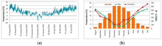
Figure 3.
Meteorological conditions in Katowice: (a) outdoor air during measurements; (b) mean monthly outdoor air temperature and heating degree days.
Measurements were performed in the first Polish office building in the passive standard on the area of Euro–Centrum Science and Technology Park (Figure 4a). The building was put into operation in February 2014. It has 5 stories with administrative, office, and conference rooms, as well as laboratories. It has a total and usable area of 8100 m2 and 7500 m2, respectively.
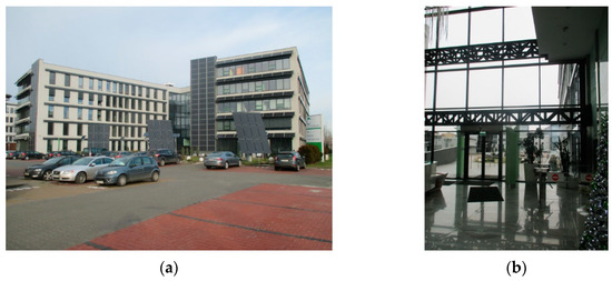
Figure 4.
(a) External view of the building; (b) glazed entrance/view from the interior of the building.
Several energy-saving solutions and renewable energy technologies were applied here. Compact structure minimizes the risk of thermal bridges, and the large glazing allows for the use of heat gains from solar radiation and provides natural light. To increase the use of daylight, when designing the communication system, central glazing was used (Figure 4b), and office rooms were located around the perimeter of the building.
External walls were insulated with 30 cm thick polystyrene and energy-saving three-pane windows, equipped with external blinds that protect against overheating of rooms, in order to reduce heat losses in the building.
Heating and cooling are provided by the low temperature thermally activated building system (TABS), underfloor system (only basement), and additionally by the heating and cooling coils in all AHUs in the building. They are supplied from the cascade-connected to 3 two-compressor water/water heat pumps with the total heating and cooling capacity of 244 kW and 187 kW, respectively [59]. Additional 10 vacuum solar collectors are used to heat utility water and support the heating system. Hydraulic scheme of the HVAC system is presented in Figure 5.
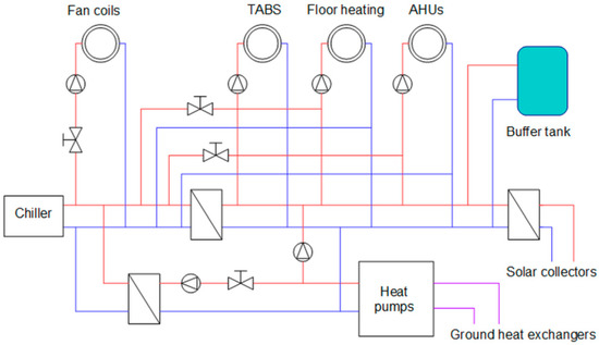
Figure 5.
Schematic diagram of the heating, ventilation, and air conditioning system in the building.
Because of its size, the building was equipped with 5 AHUs. Fourth of them are with rotary heat exchangers and supply fresh air to office, conference, technical, and social rooms. They have a common intake and exhaust collector on the roof. The fifth AHU is with cross-flow heat exchanger and supplies fresh air to sanitary facilities, toilets, and restrooms. This AHU, due to the fact that it serves rooms with a different function to other systems, is equipped with a separate air intake and exhaust on the roof.
Electricity consumption in the building is significantly covered by photovoltaic modules of total power of 107 kWp. They were mounted on the roof (231 modules) and on the façade (108 modules vertically on the façade and 80 modules arranged in rows between the windows). In addition, 36 modules were mounted on 3 trackers in front of the building (south direction).
Energy consumption optimization is ensured by the building management system (BMS), which regulates the operation of individual devices and controls the indoor conditions in the building.
In the described case, the calculation method resulted from practical limitations. For service and exploitation requirements, it was possible to use only variables available in the BMS system (Figure 2b), i.e., temperature (measured by the Pt1000 sensors) and airflow (measured by the piezoelectric sensors) denoted “T” (t11, t21, and t22,s) and “F”, respectively. BMS also provided measurements of thermal power of fan coils. Electricity consumption by fan motors was obtained on the basis of ventilation airflow rate and fans’ characteristics. "Multical 602" heat meters of Kamstrup were used in fan coil thermal energy measurements. According to the manufacturer’s data, the measurement accuracy is of ±1 °C and ±5% for temperature and airflow control purposes, respectively. At low values of temperature differences, t11−t21 possibility of computational errors (Equation (1)) exists. At the same time, measurement error may be a substantial part of the measured temperature difference. To avoid such error sources, we decided to filter out all data records with temperature differences below 2 K.
The considered AHU is 1of 5 installed in the building. It supplies fresh air to sanitary and utility rooms of a total area of 717.91 m2 and volume of 2153.8 m3. Polish ventilation standards in residential buildings have been described recently [60,61,62]. In commercial or industrial buildings, this issue is addressed in [63]. In the case of mechanical ventilation in hygienic and sanitary rooms, air exchange should be provided in the amount of no less than 50 m3/h for 1 toilet bowl and 25 m3/h for 1 urinal.
The main parameters of the tested air handling unit are presented in Table 1. Because t22,s was measured, then t22,f was computed from Equation (5). Then t22 was obtained from t22,f, assuming constant air temperature rise of 0.9 °C declared by the manufacturer.

Table 1.
Technical parameters of AHUs.
3. Results and Discussion
3.1. Ventilation Airflow
Operation of the analyzed AHU is strictly dependent on working hours of a building. It is switched on 2–4 h before opening hours and stopped in a similar manner, about 2–4 h after closing hours. This is due to proper airing of offices because the main task of this system is to deliver fresh air and remove used air because of sanitary and hygienic reasons. In the summer period, these additional ventilation hours allow cool air to flow inside the building during the day. On non-working days, ventilation is switched off. This schedule for the whole week from 1 August 2015 to 7 August 2015 is shown in Figure 6.
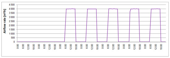
Figure 6.
Supply airflow rate from 1 August 2015 to 7 August 2015.
In the winter months, this schedule may be changed to reduce ventilation loss during the days with very low ambient temperatures. Moreover, intermittent interruptions, maintenance work, or tests influence operation of the system (Figure 7). However, the thorough analysis of the whole year operation did not reveal significant long disturbing events. Air change rate varied from 0 to 2.13 1/h. Only on 25 November 2015 from 13:00 to 17:00 did it amount to 2.53 1/h because of maintenance work and performed tests.
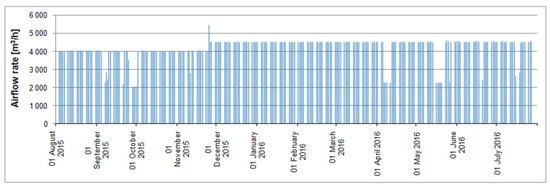
Figure 7.
Supply airflow rate from 1 August 2015 to 31 July 2016.
The analyzed period was the length of 366 days, i.e., 8784 h. The ventilation was working for 3068 h, i.e., 35% of the year. It was evenly distributed in consecutive months, from 223 h in July to 276 h in March, with 255.7 h on average.
3.2. Heat Recovery
Poland lies in the heating dominated climate [64], and thus heat recovery is of special interest. In the analyzed, period hourly temperature efficiency of heat recovery varied (Figure 8) from 4.3% on 21 September 2015 at 6:00 and 27 July 2016 at 9:00 to 99.5% on 12 April 2016 at 17:00, with 65.2% on average. It was better than 59.5% declared by the manufacturer (Table 1). When omitting temperature rise during flow of air through the supply fan, shown in Table 1, then average annual efficiency was 76.0%.
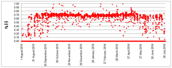
Figure 8.
Hourly efficiency of heat recovery from 1 August 2015 to 31 July 2016.
To explain the occurrence of efficiency values in such a wide range, an additional brief comment is needed. As mentioned above, its lowest value occurred twice. In the first case, it was just after start of the ventilation system. During the nighttime break, still air inside the ventilation duct warmed up. After turning on the fan, fresh and cold outside air was sucked into the duct. Its temperature dropped (Figure 9a) but was still higher than that of the outdoor air, resulting in low efficiency (Equation (1)). The second situation took place in July, during the cooling period, because instantaneous thermal conditions, resulting mainly from varying solar and internal gains, resulted in t21 < t22 < t11 (Figure 9b).
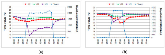
Figure 9.
Temperatures t11, t21, and t22 and ventilation airflow on (a) 21 September 2015; (b) 27 July 2016.
The highest value of η = 99.5% occurred on 12 April 2016 at 17:00 and η = 98.7% on 4 November 2015 at 15:00. Thermal conditions in both cases are illustrated in Figure 10. They were influenced by uneven work of ventilation.
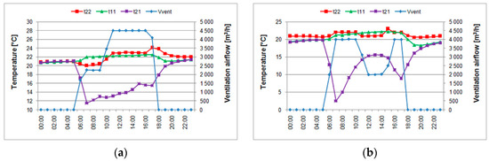
Figure 10.
Temperatures t11, t21, and t22 and ventilation airflow on (a) 12 April 2016; (b) 4 November 2015.
Despite the presence of low and high efficiency values, Figure 1 shows that intermediate values, in the range of 60%–70%, prevailed. A more detailed analysis of this phenomenon is possible on the basis of the efficiency histogram presented in Figure 11.
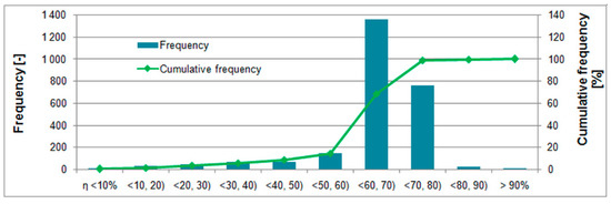
Figure 11.
Histogram of calculated hourly efficiency of heat recovery.
From the total of 2633 h during the year when heat recovery was possible, 131 h was extracted because of measurement restrictions described in Section 2.2 resulting in 2502 analyzed hours. From them, efficiency from 60% to 70% and from 70% to 80% was achieved during 1356 h and 758 h, respectively. Hence, the interval from 60% to 80% covered 84.5% of time with heat recovery.
Heat recovery was also possible in hot months (cooling period) due to favorable dynamic thermal conditions, from 90 h (35.9% of total operation hours of ventilation system in that month) in August to 275 h in December. Monthly efficiency (Table 2) was from 37.6% in August to 68.7% in May. The total number of operation hours of the ventilation system includes building’s working hours plus pre-ventilation and post-ventilation periods, typically 2–3 h each daily.
Table 2.
Monthly temperature efficiency of heat recovery.
Another important characteristic is dependence of the efficiency on outdoor air temperature (Figure 12), providing information about the usefulness of a given device under certain temperature conditions. As is shown, temperature efficiency slightly increases with the increasing outdoor temperature but still has satisfying value at lower temperatures when heating is needed. Similar observations were also presented by other researchers [65,66].
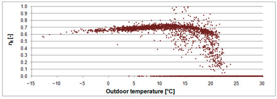
Figure 12.
Hourly efficiency of cold recovery from 1 August 15 to 31 July 16.
To clarify the issue of efficiency calculation, we present here an example for the day 5 January 2016. At 10:00, we measured = 4504 m3/h, t11 = 21.1 °C, t21 = −3.6 °C, t22,s = 22.9 °C, and = 14.0 kW.
From Equation (6), air density at given t22 is ρ = 1.19289 kg/m3. From Equation (7) specific heat capacity of air cp = 1006.19 J/kg∙K. Inserting these values into Equation (5), we obtain
t22,f = 22.9 − 14000/(1.19289 ∙ 1.2511 ∙ 1006.19) = 13.58 °C
Assuming temperature rise of air in the fan (see Table 1) of 0.9 °C, we obtain
t22 = 13.58 − 0.9 = 12.68 °C
Inserting computed t22 and measured t11 and t21 into Equation (1), we obtain ηt = 0.659. If assumed temperature rise in fan is omitted, then t22 = t22, = 13.58 °C and ηt = 0.696.
Rewriting Equation (1), we obtain
t22 = ηt (t11− t21) + t21
This way, unknown supply temperature can be obtained at given outdoor and exhaust temperature and temperature efficiency. Assuming ηt = 0.595 given in Table 1, we computed t22 for the same outdoor and indoor temperatures, which we compared with previous results (Figure 13). Strong correlation indicates that use of ηt declared by the manufacturer is justified in practice.
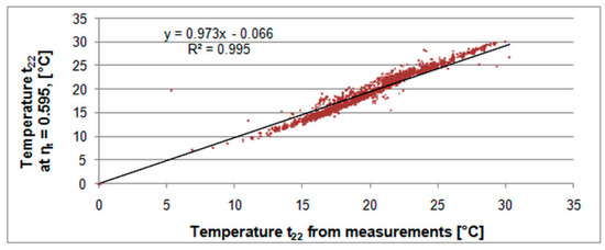
Figure 13.
Cold recovery efficiency versus outdoor temperature.
3.3. Cold Recovery
Cold recovery means mainly the possibility to cool heated building’s interior by outdoor cold air during nights. This phenomenon occurred from April to September in a total of 127 h. Temperature efficiency of cold recovery varied (Figure 14) from 16.7% on 16 June 2016 at 11:00 to 95.2% on 5 July 2016 at 16:00 at outdoor air temperatures of 24.2 °C and 26.0 °C, respectively. Monthly efficiency was from 59.5% in June to 67.9% in September, with 64.6% on average.
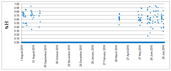
Figure 14.
Unit electricity consumption (-), heat and cold savings (+).
Moreover, in this case, we can compare cold recovery efficiency with outdoor air temperature (Figure 15). However, because of the small number of the measured values and short cooling period, this dependence is not clear in terms of the case of heating.
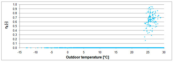
Figure 15.
Heat recovery efficiency versus outdoor air temperature.
3.4. Energy Savings
Energy savings obtained thanks to the AHU with heat exchanger require certain electricity input to drive the fans. During the analyzed period, both fans consumed 7626 kWh with maximum and minimum of 485.6 kWh and 786.3 kWh in February and December, respectively. Energy savings and consumption by fans related to the conditioned area (Figure 16) varied from 0.31 kWh/m2 in August to 6.61 kWh/m2 in January and from 0.68 kWh/m2 in February to 1.04 kWh/m2 in March. Net energy flow of this AHU was from −0.46 kWh/m2 in August, when consumption by fans exceeded savings, to 5.60 kWh/m2 in January.
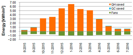
Figure 16.
Correlation of temperature t22 calculated from measurements and for constant ηt.
Annual savings of heat and cold, calculated from Equation (8), amounted to 25.6 MWh and 0.26 MWh, respectively. When the same ventilation system but with no recuperation is used, an equivalent amount of heating and cooling energy should be delivered from the existing sources. Supposing compressor heat pumps with seasonal Coefficient of Performance (COP) = 4.5 and COP = 3.5 as main sources for heating and cooling, respectively, we calculated an additional amount of consumed electricity (Table 3) under the same temperature conditions.
Table 3.
Monthly heat and cold savings and equivalent electricity consumption.
Calculated annual additional consumption of electrical energy by heat pumps amounted to 5.8 MWh, resulting in estimated cost of EUR 577.00 (0.1 EUR/kWh in Poland). Market research carried out by researchers indicated that the price of a cross-flow exchanger with additional accessories is EUR 4000, meaning simple payback time (SPBT) of such an investment is less than 7 years. Comparison with typical lifespan of AHUs of 15−20 years [67] indicates a good economic efficiency of the use of such a device.
4. Conclusions
Heat recovery from ventilation air in the Polish heating-dominated climate may result in significant energy and financial savings. The presented case study of air handling unit with the cross-flow heat exchanger proved its proper operation. Taking into account only recovered heat and referring it to the conditioned area of the building, we obtained the value of 35.7 kWh/m2. This is unit final energy, which does not have to be supplied via the HVAC system to the interior of the building in order to maintain required set temperature. Of course, energy to drive exhaust and supply fans was not included here because ventilation must continue to function. This value may significantly affect the energy class of a building. Hence, energy-efficient technologies should be implemented and studied during operation to provide reliable outcomes for investors, users, and policymakers.
Funding
This research received no external funding.
Institutional Review Board Statement
Not applicable.
Informed Consent Statement
Not applicable.
Data Availability Statement
Not applicable.
Acknowledgments
The author would like to express gratitude to Stanisław Grygierczyk, the scientific and environmental coordinator at the Euro-Centrum Science and Technology Park in Katowice, for his support during research.
Conflicts of Interest
The author declare no conflict of interest.
References
- Lis, P. Energy saving and reduction of emissions in heating residential buildings in Poland—Potential and selected activities. E3S Web Conf. 2019, 116, 00044. Available online: https://www.e3s-conferences.org/component/makeref/?task=show&type=html&doi=10.1051/e3sconf/201911600044 (accessed on 8 March 2021). [CrossRef]
- Dołęga, W. Selected aspects of national economy energy efficiency. Polityka Energetyczna Energy Policy J. 2019, 22, 19–32. [Google Scholar] [CrossRef]
- Kozik, R.; Jaśkowiec, I.K.; Filipowicz, M.; Dudek, M.; Olkuski, T.; Styszko, K. Green public procurement—Legal base and instruments supporting sustainable development in the construction industry in Poland. E3S Web Conf. 2016, 10, 44. Available online: https://www.e3s-conferences.org/component/makeref/?task=show&type=html&doi=10.1051/e3sconf/20161000044 (accessed on 8 March 2021). [CrossRef]
- Ramczyk, M. Legal bases and economic conditions of applying renewable energy resources in construction industry. MATEC Web Conf. 2018, 174, 04004. Available online: https://www.matec-conferences.org/component/makeref/?task=show&type=html&doi=10.1051/matecconf/201817404004 (accessed on 9 March 2021). [CrossRef][Green Version]
- Firląg, S. Cost-Optimal Plus Energy Building in a Cold Climate. Energies 2019, 12, 3841. [Google Scholar] [CrossRef]
- Regulation of the Minister of Infrastructure and Development of 27 February 2015 on the Methodology to Determine the Energy Performance of a Building or Part of a Building, and Energy Performance Certificates, Dz.U. 2015, Item 376, as Amended. Available online: http://isap.sejm.gov.pl/isap.nsf/DocDetails.xsp?id=WDU20150000376 (accessed on 5 February 2021).
- Redlarski, G.; Wojdalski, J.; Kupczyk, A.; Piechocki, J. Efficiency of biomass energy used for heating purposes in a residential building in comparison with other energy sources. Teka—Comm. Mot. Energetics Agric. 2012, 12, 211–218. [Google Scholar]
- Basińska, M.; Koczyk, H. Analysis of the possibilities to achieve the low energy residential buildings standards. Technol. Econ. Dev. Econ. 2016, 22, 830–849. [Google Scholar] [CrossRef]
- Krawczyk, D.A. Analysis of Energy Consumption for Heating in a Residential House in Poland. Energy Procedia 2016, 95, 216–222. [Google Scholar] [CrossRef]
- Piotrowska, E.; Borchert, A. Energy consumption of buildings depends on the daylight. E3S Web Conf. 2017, 14, 1029. Available online: https://www.e3s-conferences.org/component/makeref/?task=show&type=html&doi=10.1051/e3sconf/20171401029 (accessed on 8 March 2021). [CrossRef]
- Bekierski, D.; Geryło, R.; Kaczorek, D.; Perczyński, P. EPBD Implementation in Poland, Status in December 2016, Concerted Action EPBD, 2018. Available online: https://www.buildup.eu/sites/default/files/content/ca-epbd-iv-poland-2018.pdf (accessed on 5 February 2021).
- Sobczyk, W.; Sapa, K. Energy balance in a passive solar building. An attempt at economic assessment. E3S Web Conf. 2016, 10, 86. Available online: https://www.e3s-conferences.org/component/makeref/?task=show&type=html&doi=10.1051/e3sconf/201911600044 (accessed on 8 March 2021). [CrossRef]
- Sikora, M.; Siwek, K. Energy audit of the residential building. J. Mech. Energy Eng. 2018, 2, 317–328. [Google Scholar] [CrossRef]
- Krawczyk, D.A.; BiaĹ, P. Buildings 2020+. Constructions, Materials and Installations; Bialystok—Cordoba—Vilnius 2019; Printing House of Bialystok Univesity of Technology: Białystok, Poland, 2019. [Google Scholar] [CrossRef]
- Hałacz, J.; Skotnicka-Siepsiak, A.; Neugebauer, M. Assessment of Reducing Pollutant Emissions in Selected Heating and Ventilation Systems in Single-Family Houses. Energies 2020, 13, 1224. [Google Scholar] [CrossRef]
- Hajdukiewicz, M.; Goggins, J. The influence of heat transfer and storage in structural precast building components on in-door environments. In Proceedings of the Civil Engineering Research in Ireland (CERI 2014), Belfast, Ireland, 28–29 August 2014. [Google Scholar]
- Wąs, K.; Radoń, J.; Sadłowska-Sałęga, A. Maintenance of Passive House Standard in the Light of Long-Term Study on Energy Use in a Prefabricated Lightweight Passive House in Central Europe. Energies 2020, 13, 2801. [Google Scholar] [CrossRef]
- Papadopoulos, A.M.; Papageorgiou, K.P.; Karatzas, K. Evaluation of an attached sunspace without sun protection: How feasible is this approach in mediterranean summer conditions? Int. J. Sol. Energy 2002, 22, 93–104. [Google Scholar] [CrossRef]
- Pyloudi, E.; Papantoniou, S.; Kolokotsa, D. Retrofitting an office building towards a net zero energy building. Adv. Build. Energy Res. 2014, 9, 20–33. [Google Scholar] [CrossRef]
- Witkowska, A.; Krawczyk, D.A.; Rodero, A. Investment Costs of Heating in Poland and Spain—A Case Study. Proceedings 2019, 16, 40. [Google Scholar] [CrossRef]
- Bakonyi, D.; Dobszay, G. Simulation aided optimization of a historic window’s refurbishment. Energy Build. 2016, 126, 51–69. [Google Scholar] [CrossRef]
- Hurnik, M.; Specjal, A.; Popiolek, Z.; Kierat, W. Assessment of single-family house thermal renovation based on comprehensive on-site diagnostics. Energy Build. 2018, 158, 162–171. [Google Scholar] [CrossRef]
- Kostka, M.; Szulgowska-Zgrzywa, M. Change-over natural and mechanical ventilation system energy consumption in single-family buildings. E3S Web Conf. 2017, 22, 00086. Available online: https://www.e3s-conferences.org/component/makeref/?task=show&type=html&doi=10.1051/e3sconf/201911600044 (accessed on 8 March 2021). [CrossRef]
- Pietkun-Greber, I.; Suszanowicz, D. The consequences of the inappropriate use of ventilation systems operating in indoor swimming pool conditions—Analysis. E3S Web Conf. 2018, 45, 00064. Available online: https://www.e3s-conferences.org/component/makeref/?task=show&type=html&doi=10.1051/e3sconf/201911600044 (accessed on 8 March 2021). [CrossRef]
- Xu, Q.; Riffat, S.; Zhang, S. Review of Heat Recovery Technologies for Building Applications. Energies 2019, 12, 1285. [Google Scholar] [CrossRef]
- Ratajczak, K.; Szczechowiak, E. The Use of a Heat Pump in a Ventilation Unit as an Economical and Ecological Source of Heat for the Ventilation System of an Indoor Swimming Pool Facility. Energies 2020, 13, 6695. [Google Scholar] [CrossRef]
- Kostka, M. Hybrid ventilation in residential buildings—the proposal of research for the Polish climatic conditions. E3S Web Conf. 2017, 17, 43. Available online: https://www.e3s-conferences.org/component/makeref/?task=show&type=html&doi=10.1051/e3sconf/201911600044 (accessed on 8 March 2021). [CrossRef]
- Fidorów-Kaprawy, N.; Kostka, M.; Szulgowska-Zgrzywa, M.; Piechurski, K. The energy concept of the building as a part of sustainable construction. Architects 2017, 49, 115–130. [Google Scholar] [CrossRef]
- Regulation of the Minister of Infrastructure of April 12, 2002 on the technical conditions to be met by buildings and their location. J. Laws 2019, 1065, 1–112.
- Wang, F.; Yang, W.-J.; Sun, W.-F. Heat Transfer and Energy Consumption of Passive House in a Severely Cold Area: Simulation Analyses. Energies 2020, 13, 626. [Google Scholar] [CrossRef]
- Zemitis, J.; Borodinecs, A. Energy saving potential of ventilation systems with exhaust air heat recovery. IOP Conf. Series: Mater. Sci. Eng. 2019, 660, 012019. Available online: https://iopscience.iop.org/article/10.1088/1757-899X/660/1/012019 (accessed on 8 March 2021). [CrossRef]
- Luc, K.M.; Kotol, M.; Lading, T. Energy-efficient Building in Greenland: Investigation of the Energy Consumption and Indoor Climate. Procedia Eng. 2016, 146, 166–173. [Google Scholar] [CrossRef]
- Biała, A. A comparative analysis of natural and mechanical ventilation on the example of a single family house. Architectus 2020, 145–160. [Google Scholar] [CrossRef]
- Tomczak, K.; Kinash, O. Assessment of the Validity of Investing in Energy-Efficient Single-Family Construction in Poland—Case Study. Arch. Civ. Eng. 2016, 62, 119–138. [Google Scholar] [CrossRef][Green Version]
- Emmi, G.; Mariotti, M.; Zarella, A.; De Carli, M. The use of air handling units in residential near zero-energy buildings. Energy Sustain. 2017, 224, 147. [Google Scholar] [CrossRef]
- Sobczyk, W.; Sobczyk, E.J. Thermal comfort in a passive solar building. IOP Conf. Series: Earth Environ. Sci. 2019, 214, 012069. Available online: https://iopscience.iop.org/article/10.1088/1755-1315/214/1/012069 (accessed on 9 March 2021). [CrossRef]
- Kwiatkowski, J.; Rucińska, J. Estimation of Energy Efficiency Class Limits for Multi-Family Residential Buildings in Poland. Energies 2020, 13, 6234. [Google Scholar] [CrossRef]
- Sadowska, B. The Impact of Climate Conditions on Energy Consumption for Heating and Cooling of Residential Buildings. Econ. Environ. 2018, pp. 189–197. Available online: http://www.ekonomiaisrodowisko.pl/uploads/ekonomiaiśrodowisko67/16.pdf (accessed on 5 February 2021).
- Rabczak, S.; Kut, P. Analysis of Yearly Effectiveness of a Diaphragm Ground Heat Exchanger Supported by an Ultraviolet Sterilamp. Energies 2020, 13, 2804. [Google Scholar] [CrossRef]
- Pisarev, V.; Rabczak, S.; Nowak, K. Ventilation system with ground heat exchanger. J. Ecol. Eng. 2016, 17, 163–172. [Google Scholar] [CrossRef]
- Stachura, E. A Study in Polish Housing Conditions. Methodology and Building Typology Characteristics. Real Estate Manag. Valuat. 2013, 21, 25–31. [Google Scholar] [CrossRef]
- Foryś, I.; Putek-Szeląg, E.; Ziembicka, B. An Attempt to Determine the Impact of Energy Intensity on the Market Value of Residential Units on the Example of Selected Buildings in Szczecin. Real Estate Manag. Valuat. 2020, 28, 64–79. [Google Scholar] [CrossRef]
- Borowski, M.; Mazur, P.; Kleszcz, S.; Zwolińska, K. Energy Monitoring in a Heating and Cooling System in a Building Based on the Example of the Turówka Hotel. Energies 2020, 13, 1968. [Google Scholar] [CrossRef]
- Rey-Hernández, J.M.; José-Alonso, J.F.S.; Velasco-Gómez, E.; Yousif, C.; Rey-Martínez, F.J. Performance analysis of a hybrid ventilation system in a near zero energy building. Build. Environ. 2020, 185, 107265. [Google Scholar] [CrossRef]
- Asdrubali, F.; Baldinelli, G.; Bianchi, F.; Cornicchia, M. Experimental Performance Analyses of a Heat Recovery System for Mechanical Ventilation in Buildings. Energy Procedia 2015, 82, 465–471. [Google Scholar] [CrossRef]
- EN 308:2001 Heat exchangers. Test Procedures for Establishing the Performance of Air to Air and Flue Gases Heat Recovery Devices; Polish Committee for Standardization: Warsaw, Poland, 2001. [Google Scholar]
- Anisimov, S.; Pandelidis, D.; Jedlikowski, A. Performance study of the indirect evaporative air cooler and heat recovery exchanger in air conditioning system during the summer and winter operation. Energy 2015, 89, 205–225. [Google Scholar] [CrossRef]
- Ratajczak, K.; Amanowicz, Ł.; Szczechowiak, E. Assessment of the air streams mixing in wall-type heat recovery units for ventilation of existing and refurbishing buildings toward low energy buildings. Energy Build. 2020, 227, 110427. [Google Scholar] [CrossRef]
- Valchev, S.; Mihaylov, I. Analysis of energy efficiency of air handling unit with integrated air to air heat exchanger in heating mode. E3S Web Conf. 2020, 207, 01002. Available online: https://www.e3s-conferences.org/component/makeref/?task=show&type=html&doi=10.1051/e3sconf/201911600044 (accessed on 8 March 2021). [CrossRef]
- Michalak, P.; Grygierczyk, S. Temperature efficiency of heat exchangers in air handling units. J. Mech. Energy Eng. 2019, 3, 267–272. [Google Scholar] [CrossRef]
- Melian, E.; Klein, H.; Thißen, N. Improvement of a Nusselt-Based Simulation Model for Heat Transfer in Rotary Heat Exchangers. Energies 2020, 14, 10. [Google Scholar] [CrossRef]
- Tafelmeier, S.; Longo, G.A.; Gasparella, A. Energy and Economic Performance Analysis of Heat Recovery Devices under Different Climate Conditions. International High Performance Buildings Conference, 2016, Paper 196. Available online: http://docs.lib.purdue.edu/ihpbc/196 (accessed on 5 February 2021).
- Tafelmeier, S.; Pernigotto, G.; Gasparella, A. Annual Performance of Sensible and Total Heat Recovery in Ventilation Systems: Humidity Control Constraints for European Climates. Buildings 2017, 7, 28. [Google Scholar] [CrossRef]
- Kalbasi, R.; Shahsavar, A.; Afrand, M. Reducing AHU energy consumption by a new layout of using heat recovery units. J. Therm. Anal. Calorim. 2019, 139, 2811–2820. [Google Scholar] [CrossRef]
- Michalak, P. A thermal network model for the dynamic simulation of the energy performance of buildings with the time varying ventilation flow. Energy Build. 2019, 202, 109337. [Google Scholar] [CrossRef]
- McQuillan, F.; Culham, J.; Yovanovich, M. Properties of Some Gases and Liquids at One Atmosphere; Microelectronics Heat Transfer Laboratory Report UW/MHTL 8407 G-02; University of Waterloo: Waterloo, Belgium, 1984; Available online: http://www.mhtlab.uwaterloo.ca/pdf_reports/mhtl_G02.pdf (accessed on 5 March 2021).
- Amiri, L.; De Brito, M.A.R.; Ghoreishi-Madiseh, S.A.; Bahrani, N.; Hassani, F.P.; Sasmito, A.P. Numerical Evaluation of the Transient Performance of Rock-Pile Seasonal Thermal Energy Storage Systems Coupled with Exhaust Heat Recovery. Appl. Sci. 2020, 10, 7771. [Google Scholar] [CrossRef]
- Typical Meteorological Years. The Ministry of Infrastructure and Development. Available online: https://archiwum.miir.gov.pl/strony/zadania/budownictwo/charakterystyka-energetyczna-budynkow/dane-do-obliczen-energetycznych-budynkow-1/ (accessed on 5 February 2021).
- Michalak, P. Selected Aspects of Indoor Climate in a Passive Office Building with a Thermally Activated Building System: A Case Study from Poland. Energies 2021, 14, 860. [Google Scholar] [CrossRef]
- Sowa, J.; Mijakowski, M. Humidity-Sensitive, Demand-Controlled Ventilation Applied to Multiunit Residential Building—Performance and Energy Consumption in Dfb Continental Climate. Energies 2020, 13, 6669. [Google Scholar] [CrossRef]
- Miszczuk, A.; Heim, D. Parametric Study of Air Infiltration in Residential Buildings—The Effect of Local Conditions on Energy Demand. Energies 2020, 14, 127. [Google Scholar] [CrossRef]
- Ferdyn-Grygierek, J.; Baranowski, A.; Blaszczok, M.; Kaczmarczyk, J. Thermal Diagnostics of Natural Ventilation in Buildings: An Integrated Approach. Energies 2019, 12, 4556. [Google Scholar] [CrossRef]
- Regulation of the Minister of Labour and Social Policy of September 26, 1997 on general health and safety regulations. J. Laws 2003, 169, 11614–11655. (In Polish)
- Jedrzejuk, H.; Dybiński, O. The Influence of a Heating System Control Program and Thermal Mass of External Walls on the Internal Comfort in the Polish Climate. Energy Procedia 2015, 78, 1087–1092. [Google Scholar] [CrossRef]
- Kamendere, E.; Zogla, G.; Kamenders, A.; Ikaunieks, J.; Rochas, C. Analysis of Mechanical Ventilation System with Heat Recovery in Renovated Apartment Buildings. Energy Procedia 2015, 72, 27–33. [Google Scholar] [CrossRef]
- Skrzycki, M.; Besler, M. Impact of damper opening time on work of storage matrix regenerative heat exchanger. E3S Web Conf. 2017, 17, 82. Available online: https://www.e3s-conferences.org/component/makeref/?task=show&type=html&doi=10.1051/e3sconf/201911600044 (accessed on 8 March 2021). [CrossRef]
- Congedo, P.M.; Baglivo, C.; D’Agostino, D.; Zacà, I.; D’Agostino, D. Cost-optimal design for nearly zero energy office buildings located in warm climates. Energy 2015, 91, 967–982. [Google Scholar] [CrossRef]
Publisher’s Note: MDPI stays neutral with regard to jurisdictional claims in published maps and institutional affiliations. |
© 2021 by the author. Licensee MDPI, Basel, Switzerland. This article is an open access article distributed under the terms and conditions of the Creative Commons Attribution (CC BY) license (http://creativecommons.org/licenses/by/4.0/).