
Experimental Validations of Hybrid Excited Linear Flux Switching Machine


1
Department of Electrical and Computer Engineering, COMSATS University Islamabad (Abbottabad Campus), Abbottabad 22060, Pakistan
2
Pakistan Center for Advanced Studies in Energy, University of Engineering & Technology, Peshawar 25000, Pakistan
*
Author to whom correspondence should be addressed.
Energies 2021, 14(21), 7274; https://doi.org/10.3390/en14217274
Submission received: 25 August 2021
/
Revised: 16 September 2021
/
Accepted: 18 September 2021
/
Published: 3 November 2021
(This article belongs to the Special Issue Design and Application of Electrical Machines)
Abstract
:Linear Flux Switching Machines (LFSMs) possess the capability to generate adhesive thrust force, thus problems associated with conventional rotatory electric machines and mechanical conversion assemblies can be eliminated. Additionally, the unique features of high force/power density, efficiency, and a robust secondary structure make LFSMs a suitable candidate for linear motion applications. However, deficiency of controllable air-gap flux, risk of PM demagnetization, and increasing cost of rare earth PM materials in case of PMLFSMs, and inherent low thrust force capability of Field Excited LFSMs compels researchers to investigate new hybrid topologies. In this paper, a novel Double-Sided Hybrid Excited LFSM (DSHELFSM) with all three excitation sources, i.e., PMs, DC, and AC windings confined to short moving primary and segmented secondary providing short flux paths is designed, investigated, and optimized. Secondly, unequal primary tooth width optimization and additional end-teeth at all four corners of the primary equip proposed design with balanced magnetic circuit and reduced end-effect and thrust force ripples. Thirdly, the measured experimental results of the manufactured proposed machine prototype are compared with corresponding simulated model results and shows good agreements, thus validating the theoretical study.
1. Introduction
Existing long stroke linear motion applications such as electric train and vertical lifting utilize rotatory machines plus Mechanical Conversion System (MCS). Two important problems of existing traction system can be highlighted as; (1) the installed rotatory motors are either DC series traction motor, induction motor, or newest traction system utilizes synchronous machines. DC series traction motors are excited by DC rotor bars and brushes are utilized to deliver electric power. This commutator section results in increased maintenance cost and sparking may lead to fire/faults [1]. Induction motor shows demerits of complex speed control, low starting torque, and low efficiency at low loads due to low power factor [2]. Synchronous machines result in high efficiency, constant speed, high power factor, and high torque density. However, placement of field system (PMs or electromagnets) at the rotor reduces its mechanical integrity at high speeds [3]. Furthermore, increased cost of rare earth material in case of Permanent Magnet Synchronous Machine (PMSM) and due to increased maintenance cost of collector rings and brushes in case of field excited synchronous machines forced electrical machine designers to investigate new topologies [4]. Second, MCS is required to convert rotating torque into linear thrust force, as linear translational motion is expected in case of electric train. MCS is meshing engagement of motion type conversion mechanical devices such as ball screw, lead screw and rack, and pinion, etc. This combination results in noise, vibration, mechanical power transfer loss, gearbox faults, and regular maintenance problems [5].
Linear Flux Switching Machine (LFSM) directly obtained from corresponding rotatory machine wiped out MCS requirements due to capability of generating direct thrust force, thus solving noise, vibration, and regular maintenance problems. Additionally, high force/power density, power factor, efficiency, and a unique inherent structural property of simple and robust secondary structure makes LFSMs suitable for long-distanced linear motion applications [6]. Linear motor directly obtained from corresponding rotatory machine is termed as single sided linear motor and shows a demerit of high normal or attraction forces [7]. High normal force values result in additional frictional force and reliability of the linear machine [8]. Double sided LFSM is a new introduction in the linear machines’ family that successfully solved large undesired normal/attraction force problem [9,10].
Geometric structure and excitation sources are the two parameters that helps researchers to investigate new topologies of LFSMs. Based on geometric structure, LFSMs can be divided into (a) single sided and (b) double sided designs [11]. Based on excitation sources, LFSMs can be excited by: (a) PM plus AC known as Permanent Magnet LFSM (PMLFSM), (b) DC plus AC named as Field Excited LFSM (FELFSM), and (c) PM plus DC and AC termed as Hybrid Excited LFSM (HELFSM). PMLFSM possess drawbacks of fixed and uncontrollable air-gap magnetic field density, risk of PM demagnetization, and high manufacturing cost due to rapid increase in rare-earth PM materials [12]. PMs can be replaced by DC electromagnets to design FELFSM. However, FELFSM exhibit reduced thrust force density and high copper losses. HELFSM requires serious attention of researchers due to its unique features of combining PMLFSM and FELFSM advantages such as variable air-gap field density, reduced manufacturing cost, and flux strengthening/weakening capability.
In this paper, a novel HELFSM with modular stator and complementary coil connection mover is proposed for linear motion applications. Additional assistant teeth at all four end points of the moving primary is installed to balance magnetic circuit and reduce end-effect. Modular stator design reduces secondary material consumption and provides short paths [13]. Complementary coil design enables reduced Thrust Force Ripple Ratio (TFRR) by engaging symmetrical and sinusoidal flux linkages. Disadvantages of existing design schemes installed for targeted applications along with their proposed solution are discussed in Section 2. Design topology, development guidelines, structure variables, and operation principle of proposed machine is explained in Section 3. Section 4 of this paper presents single variable geometry based deterministic optimization (SVGBDO) approach applied to uplift thrust force performance and reduce TFRR of the proposed HELFSM. During optimization process, unequal primary tooth width [14] is enabled to provide appropriate low reluctance path where high flux is recorded during initial tests. Detailed comparison of initial and optimized HELFSM, thrust-force/power versus armature current density plot, thrust-force/power versus velocity characteristics, and efficiency at eight different points of thrust force-vs-velocity graph is also presented in this section. Experimental test bed and measured results are explained in Section 5. Finally, some conclusions are summarized in Section 6.
2. Targeted Applications
Multiple methods to decrease humans’ and goods’ delivery suspension down time are experienced such as dedicated auto-mobiles, sea ships, and air cargo. However, harmful emissions due to increased use of Internal Combustion Engines (ICEs) and dependency on continuously decaying fossil fuel reservoirs make these options uneconomical [15]. Furthermore, congested road conditions and chances of fatal accidents in case of dedicated auto-mobiles, delivery time ranging from weeks to months in case of sea ships, and high costs of air travel are few reasons that compels transport industry to move towards electric trains. Similarly, due to dramatic increase of human population and consequently land prices, skyscrapers and high-rise buildings are mushrooming at a very high speed. Thus, safe and fast vertical lifting system is an essential need of the current time.
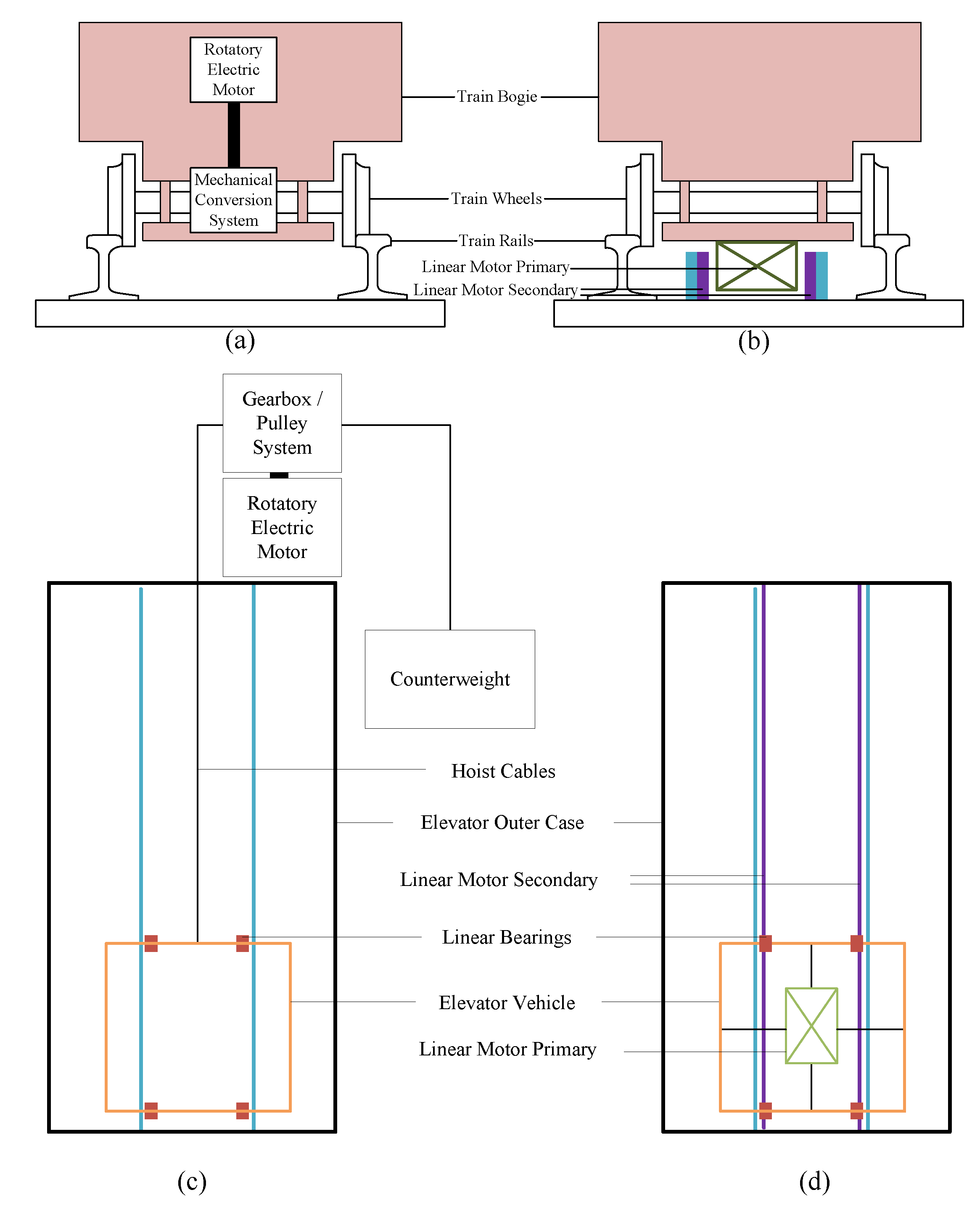
Comparison of existing and proposed traction scheme for electric train and elevator system is shown in Figure 1. Both of these proposed configurations have the ability to wipe out meshing of rotatory machines and MCS. Besides these, two disadvantages of conventional elevator system are hoist cables and counterweights. Hoist cables may suffer strength and stability failures whereas counterweights absorb significant accommodation space throughout the building height [16]. Proposed ropeless vertical elevator scheme is capable to increase stability by avoiding hoist cables and helps in better utilization of building accommodation by removing counterweights requirements.
The schematic diagram presenting solutions of existing electric train and elevator system problems identifies replacement of rotatory electric motor and MCS with a linear motor. As shown in Figure 1, secondary of the linear motor in case of electric train will be stretched along with the train rails and primary will be attached with the train bogie. This solution reflects an additional advantage of easy power supply to the linear motor primary. Regarding elevator system, primary of the linear motor is to be attached with the elevator vehicle and its secondary will be stretched along with frame of the elevator.
3. Topology and Working Principle
3.1. Topology
Three dimensional illustration and two dimensional diagram of proposed machine is shown in Figure 2 and Figure 3, respectively. Mover teeth , number of DC windings or PMs , AC windings , and stator to mover pole pitch of the proposed machine are derived utilizing following design guidelines equations [17]:
3.2. Working Principle
Two types of explanation techniques (air-gap field modulation theory [18,19] or magnetic equivalent circuit) can be utilized to understand operation principle of proposed machine. Magnetic Equivalent Circuit (MEC) methodology is adopted in this paper to reduce complexity. Positive max. and negative max. of no-load flux linkage obtained during linear displacement of one stator pole pitch are shown in Figure 5a,b, respectively. Red lines indicate flux flow generated due to PMs and makes series magnetic circuit encompassing two stators and complete mover. Flux represented by green lines is due to DC electromagnets and make combination of two parallel magnetic circuits and also follow PM flux flow paths. Both PM and DC electromagnets’ flux follow same paths to ensure philosophy of hybrid excitation.
4. Optimization and Comparisons
4.1. Optimization of Proposed HELFSM
SVGBDO is a sequential optimization approach that modify geometry variables and is aimed at improving two important performance indices. SVGBDO is conducted in two steps: (1) mover optimization and (2) stator optimization. During step 1, machine configuration with highest average thrust force is selected as optimized model. A TFRR of less than 10% is considered as optimization goal during step 2, while maintaining average thrust force of 10 kN. In other words, mover optimization is done to increase average thrust force and stator optimization is done to reduce TFRR while maintaining specific defined average thrust force limit. Stator pole pitch, mover pole pitch, stack length, air-gap height, whole machine height, primary length (x-direction), armature and field excitation current densities, PM volume, slot area, number of AC and DC coil turns, and mover velocity are kept constant during whole optimization process.
Unequal flux flow in the primary is due to presence of PMs in the DC tooth and is normalized by broadening PM+DC tooth width and shrinking Armature Winding (AW) tooth width in order to keep mover pole pitch constant. To optimize split ratio, mover height, mover yoke height, stator height, AW and PM+DC tooth width, slot area dimensions, PM dimensions, and stator segment dimensions, following six optimization coefficients are defined. Definitions of optimization coefficients, sequence of optimization process, initial values, constraints, and their optimized values are listed in Table 2.
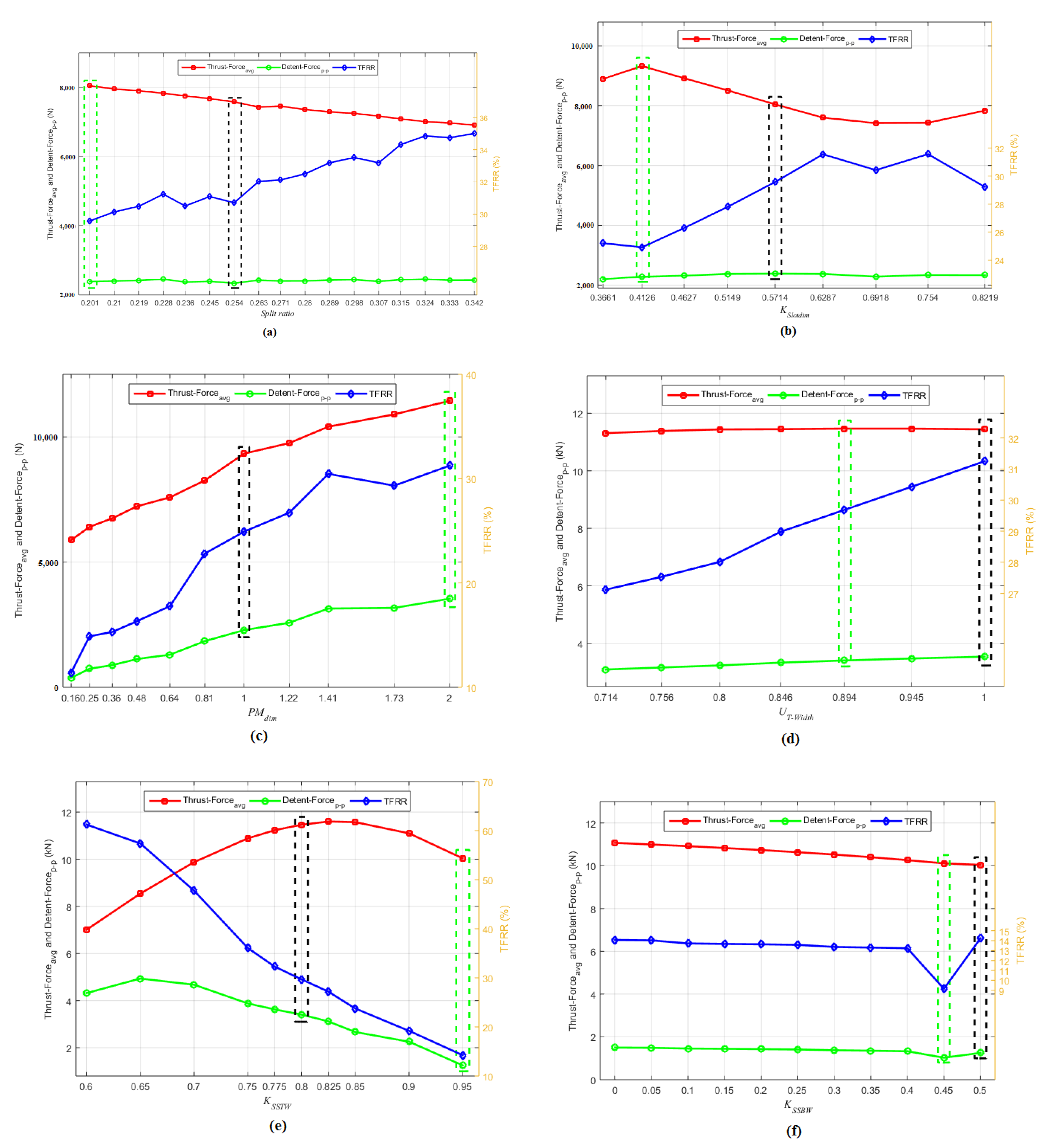
Due to sequential nature of optimization approach, only one optimization coefficient is considered at an instance and investigation is performed until its optimization is completed. In the upcoming optimization process and comparisons, different colour encircling schemes are adopted to differentiate initial and optimized machine configurations. Black colour encircling conveys performance of initial or base machine configuration whereas green rectangle represents optimized value of optimization coefficients. Keeping optimization targets in mind, three Key Performance Indicators (KPIs), i.e., no-load detent force, on-load average thrust force, and TFRR are analysed during upcoming optimization process comparisons. Once, the optimization of an optimization coefficient is completed, the geometrically updated machine configuration is subjected to next optimization coefficient analysis. Detailed procedure of optimization approach is given in Figure 6a–f.
4.1.1. Split Ratio Optimization
Split ratio can be defined as ratio of stator to whole machine volume. As discussed in previous section, depth or stack length, whole machine height, and x-direction length of proposed HELFSM are kept constant during optimization process. Hence only stator, mover, and air-gap heights are incorporated in the split ratio coefficient defined in Table 2. As whole machine height is constant, any variation either increase or decrease in the mover height will be reflected in the same amount of decrement or increment of stator segment height. Two geometric variables, which are supposed to be altered are (1) mover yoke height and (2) stator segment height. Smaller value of split ratio coefficient will result in higher mover and lower stator volume. This condition reduces secondary material consumption and provides large cross sectional area to flux flow at the mover yoke height. In order to avoid saturation effect at stator segments, minimum value of split ratio coefficient is defined as 0.2. Maximum value of split ratio coefficient is limited by mechanical stability and manufacturing constraints of mover, as higher value of mentioned coefficient reduces mover yoke height.
Analysing Figure 6a, it can be seen that influence of split ratio coefficient is directly proportional to TFRR, shows the inverse relation with average thrust force, and does not shows strong influence on detent force profile. Minimum value of the split ratio coefficient results in average thrust force, peak-to-peak detent force, and TFRR of 8048.43 N, 2386.5 N, and 29.58%. Whereas maximum value of the split ratio coefficient reflects average thrust force, peak-to-peak detent force, and TFRR of 6910.55 N, 2426.07 N, and 35%. Observing KPIs trends with respect to split ratio coefficient and keeping in mind about selection of machine configuration with maximum average thrust force during mover optimization, HELFSM having split ratio coefficient of 0.201 is selected as optimized machine configuration and it is subjected for further analysis.
4.1.2. Slot Area Dimensions Optimization
Dimensions of AW and Field Excitation Coils (FECs) are optimized while keeping mover pole pitch and winding slot area constant. Under constant slot area constraint, increase in slot area width will result in decrease of slot area height and also reduces primary tooth width. This ultimately affects mover yoke height. Similarly, decrement of slot area width will directly influence machine’s geometry by increasing mover tooth width and reducing mover yoke height. So, the geometric variables prone to variations are (1) primary tooth width and (2) mover yoke height. Slot area dimension coefficient declared in Table 2 have direct relation with width of slot area and inverse relation with height of slot area. Hence, minimum value of the slot area coefficient will result in reduced slot opening and mover yoke height.
It should be noted that the optimized machine configuration obtained from split ratio optimization step is considered as base machine configuration in this subsection and is subjected to slot area dimensions optimization. In order to avoid saturation effect at mover yoke height, minimum value of slot area coefficient is limited as 0.3661 reflecting mover yoke height of 3.6 mm. Maximum value of the mentioned coefficient will reduce mover tooth width and must be limited to avoid saturation. Hence, maximum value of slot area coefficient is selected as 0.8219 representing mover tooth width of 5.5 mm.
It can be seen that influence of slot area coefficient is non-linear in case of average thrust force and TFRR (Figure 6b). However, its influence is not that much significant in case of detent force profile. Regarding average thrust force, an increase at initial step is observed and then it goes on decreasing. Inversely, a decrease in TFRR profile is recorded at start and then it goes on increasing. Investigation of KPIs’ numerical values and search for machine configuration with maximum average thrust force compelled the author to select slot area coefficient of 0.4126. Machine configuration with slot area width of 8.5 mm, slot area height of 20.60 mm resulted in slot area coefficient of 0.4126 and it is subjected to next stage of optimization process.
4.1.3. PM Dimensions Optimization
PM’s width and length are optimized while keeping mover tooth width and total PM volume constant. As can be seen in the topology of the proposed machine, mechanical integrity of the linear machine is enhanced by burying PMs in the tip of primary teeth and primary core portion on both sides of the PM is used to firmly hold the external body. This additional primary core area is capable to avoid PM loss/drop and PM demagnetization during flux weakening operation, as FEC flux will find dedicated low reluctance path to flow. Increase in PM width will result in decrease of PM height and primary core area that is used for clamping of PMs and bypass path for FEC flux. Similarly, decrement of PM width will influence machine’s geometry by increasing PM height and width of primary core area. In addition to PM width and height, the only geometric variable that is altered during this optimization stage is primary core area at both sides of PM. PM dimensions coefficient declared in Table 2 have direct relation with PM width and inverse relation with height of PM. Minimum value of the PM dimensions coefficient is limited due to manufacturing constraints of PM and it is selected as 0.16 resulting in a PM width of 2 mm. Maximum value of PM dimensions coefficient is selected as 2.00 that allows primary core width of 1 mm at each side of PM, any further increment in the mentioned coefficient may cause saturation at the specific location.
As practised in previous subsection, optimized machine configuration obtained from slot area optimization stage is considered as base machine configuration in this subsection and is subjected to PM dimensions optimization. All three KPIs of Figure 6c are almost linearly increasing with increment of PM dimensions coefficient and may shows same behaviour after the maximum limit of constraints. However, constraints of the optimization coefficient must be followed for realization of mechanically stable prototype. As PM is one of the major excitation source and strongly influence the performance, maximum value of the average thrust force (i.e., 11,441.09 N) is achieved when PM dimensions coefficient is 2.00, PM width is 7 mm, PM height is 3.5 mm, and each primary core area at both sides of the PM is 1 mm.
4.1.4. Unequal Primary Tooth Width Optimization
Figure 7a shows the on-load magnetic flux lines of HELFSM optimized during PM dimensions optimization. It can be seen that, both AW and PM+DC tooth shows same width dimensions. On-load flux lines are displayed in this optimization stage to evaluate quantity of magnetic flux density in the AW and PM+DC tooth at rated armature current density. In depth analysis revealed that primary tooth with PM+DC is highly populated when compared to that of AW tooth. In order to convert highly populated primary tooth into low reluctance path and increase primary core utilization ratio, Unequal Tooth Width Optimization (UTWO) coefficient is defined in Table 2. Reduction in reluctance of highly populated primary tooth is possible by increasing its width. The purpose of UTWO coefficient is to increase PM+DC tooth width and reduce AW tooth width while keeping mover pole pitch and slot area dimensions constant. The fraction of millimetres added to PM+DC tooth width must be equal to the fraction of millimetres subtracted from AW tooth width. An increment of 0.25 mm in PM+DCC tooth width is utilized, and seven different machine configurations were examined. UTWO coefficient shows direct relation with AW tooth, hence maximum value of the coefficient is selected as 1.00 when PM+DC tooth width is equal to AW tooth width. Minimum value of the mentioned coefficient is decided as 0.714, when PM+DC tooth width is equal to 10.5 mm and AW tooth width is 7.5 mm. Electromagnetic performance of HELFSM optimized in PM dimensions optimization section under different UTWO coefficient values are compared and presented in Figure 6d.
It can be seen that UTWO coefficient shows strong relation with TFRR, linearly lower gradient increasing plot of detent force, and merely influence average thrust force. Base machine configuration’s results are shown in black encircled plot of Figure 6d and by reducing AW tooth width, maximum average thrust force of 11,464.85 N is achieved at UTWO coefficient of 0.894. The maximum average thrust force machine configuration results in PM+DC tooth width and AW tooth width of 9.5 mm and 8.5 mm, respectively. A HELFSM with the novelty of unequal primary tooth width is successfully realized and its on-load magnetic flux lines are shown in Figure 7b. Mover optimization is completed at this stage. Three KPIs, i.e., average thrust force, peak-to-peak detent force, and TFRR of 11,464.85 N, 3407.63 N, and 29.68%, respectively, are achieved.
4.1.5. Stator Segment Tip Width Optimization
Stator Segment Tip Width (SSTW) can be defined as the portion of stator segment facing primary teeth and it is the gateway of flux linkage to link in between stator and mover. Wider SSTW will allow flux linkage for major portion of the electrical cycle or x-direction displacement. In this subsection, SSTW is optimized with respect to constant stator pole pitch. Initial value of SSTW simulated for HELFSM optimized during UTWO subsection is 24 mm reflecting SSTW optimization coefficient described in Table 2 of 0.8. Minimum value of the SSTW optimization coefficient is set at 0.6, when SSTW is equal to 18 mm. Further reduction is also possible; however, it degrades the proposed machine performance. Maximum value of the SSTW optimization coefficient is set as 0.95. Mentioned optimization coefficient can be further increased to 1.00; however, at that point SSTW will be equal to stator pole pitch, the secondary will become long uniform rectangle, and concept of segmented secondary will not be maintained.
Figure 6e indicates that increase of SSTW optimization coefficient shows strong and negative slope effect on peak-to-peak detent force and TFRR. Thrust force profile show increasing behaviour up to SSTW optimization coefficient of 0.825 and then decreasing. Observing KPIs trends with respect to SSTW optimization coefficient and keeping in mind about selection of machine configuration with minimum TFRR while maintaining average thrust force of 10 kN, HELFSM having SSTW optimization coefficient of 0.95 is selected as optimized machine configuration and it is subjected for further analysis. Mentioned optimization coefficient of 0.95 results is SSTW of 28.5 mm.
4.1.6. Stator Segment Base Width Optimization
Stator Segment Base Width (SSBW) defines the dimension of stator segment facing opposite to SSTW. Initial value of SSBW is fraction (half) of SSTW optimized in previous section (SSTW Optimization). Optimized machine configuration of SSTW optimization coefficient resulted in SSTW of 28.5 mm and according to calculations SSBW became 14.25 mm. Hence, the initial value of SSBW optimization coefficient defined in Table 2 will result in 0.5 while utilizing SSBW of 14.25 mm and SSTW of 28.5 mm. Value of 0.5 is considered as maximum value of the SSBW optimization coefficient and results in one stator segment volume of 2030 mm. In order to bring TFRR below 10% and reduce secondary manufacturing cost by reducing stator segment volume, minimum value of the SSBW is considered as zero.
It can be verified from Figure 6f that all three KPIs shows lower gradient negative slope graph with increase of SSBW optimization coefficient. However, a sudden dip in the peak-to-peak detent force and TFRR profile is witnessed at SSBW optimization coefficient of 0.45. Numerical values of average thrust force, peak-to-peak detent force, and TFRR at SSBW optimization coefficient of 0.45 and SSBW of 12.825 mm are 10,111.13 N, 1028.83 N, and 9.15%.
Targets defined in the start of optimization process (i.e., average thrust force of 10 kN with TFRR of less than 10%) are successfully achieved. Detailed comparisons of important KPIs based on numerical values and corresponding waveforms of initial HELFSM and geometrically optimized HELFSM is done in next section. All KPIs due to three excitation types, i.e., PMs, DC, and PM+DC are analysed separately for in depth investigation. Furthermore, initial and updated geometry based parameters are compared and presented for reproduction.
4.2. Comparison of Initial and Optimized HELFSM
No-load and on-load KPIs recorded under PMs, DC electromagnets, and combined excitations of initial and optimized HELFSM are compared in Figure 8, Figure 9 and Figure 10, respectively. Numerical values of optimized structure design variables are depicted in Table 1, whereas detailed and quantitative electromagnetic performance comparison of initial and optimized HELFSM is illustrated in Table 3. Average thrust force and power versus variable armature current density plot of optimized HELFSM at fixed field excitation is presented in Figure 11. Furthermore, average thrust force and power versus velocity graph of optimized HELFSM is shown in Figure 12. Furthermore, efficiency of optimized HELFSM at eight different points considering core and copper losses is computed and presented.
4.2.1. No-Load Flux Linkage
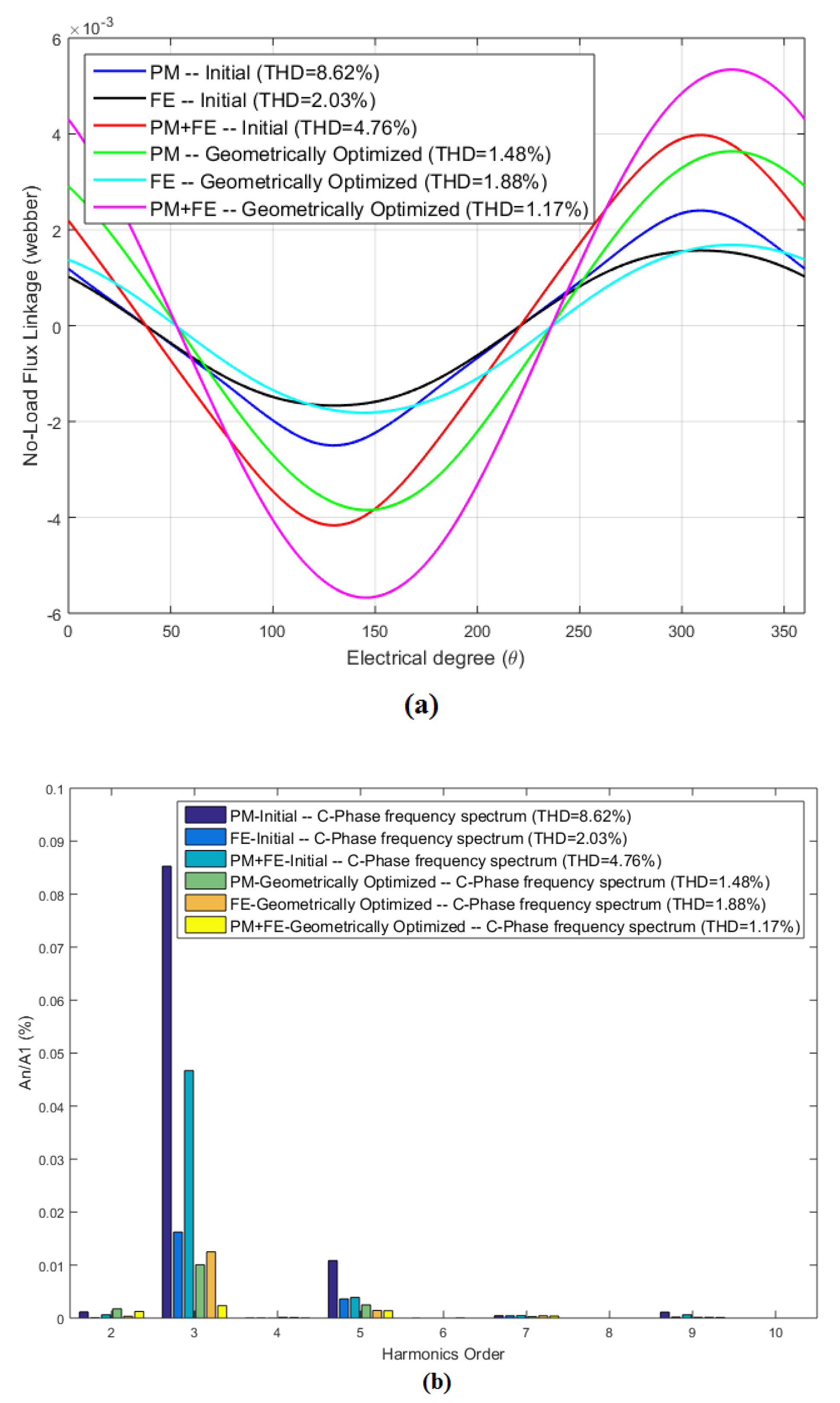
Open-circuit flux linkage waveform comparison of the initial HELFSM and geometrically optimized HELFSM is presented in Figure 8a. All three types of excitation sources are separately analysed and combined in one plot to understand their true behaviour. In order to increase ease of understanding, only centre phase (C-Phase) flux linkage is presented. Frequency spectrum up to tenth order harmonic and THD of corresponding no-load flux waveform is also shown in Figure 8b. It can be seen that peak-to-peak values of geometrically optimized HELFSM are greater in magnitude, more sinusoidal, and more symmetrical. Magnitude of peak-to-peak no-load flux linkage is increased from 8.10 mWb to 10.90 mWb. Detailed analysis of PM+DC excited machine’s frequency spectrum revealed that the dominant third and fifth order harmonics resulting in THD of 4.76% are effectively curtailed during optimization process and THD is reduced to 1.17%.
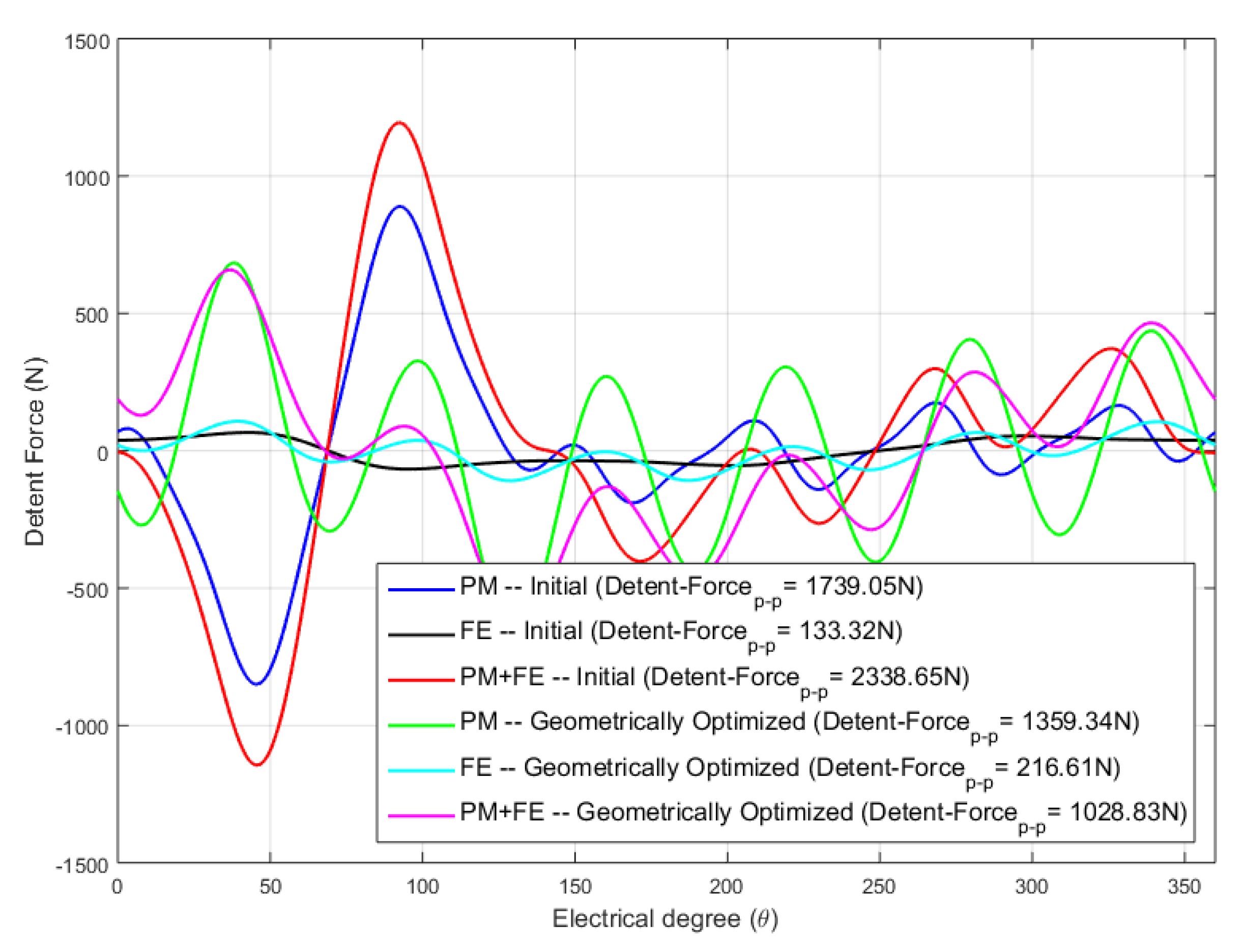
4.2.2. Detent Force
Comparison of detent force profile under all three excitation sources combinations for initial HELFSM and geometrically optimized HELFSM is presented in Figure 9. As detent force is an undesired property, it causes ripples in the thrust force profile, and affects machine’s positioning precision [20], hence its peak-to-peak value must be reduced after optimization process. While comparing initial and optimized machine configurations, peak-to-peak values of detent force due to only PMs excitation is reduced from 1739.05 N to 1359.34 N and due to PMs + DC is reduced from 2338.35 N to 1028.83 N. However, a slight increase in the peak-to-peak detent force values due to only DC excitation is observed, its value is increased from 133.32 N to 216.61 N.
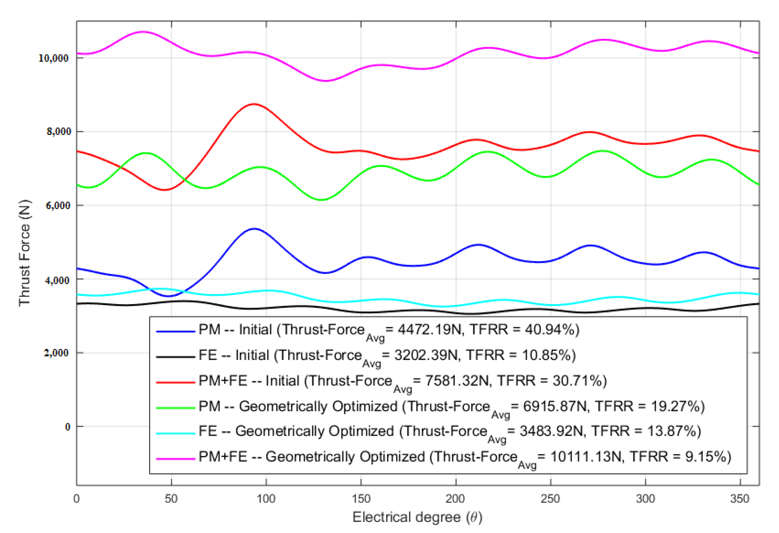
4.2.3. Thrust Force and TFRR
Unidirectional thrust force profile of the initial HELFSM and geometrically optimized HELFSM under three different excitation sources methodology is compared in Figure 10. Average thrust force under PMs excitation is improved from 4472.19 N to 6915.87 N whereas its TFRR is reduced from 40.94% to 19.27%. Similarly, average thrust force under PMs + DC excitation is improved from 7581.32 N to 10,111.13 N whereas its TFRR is reduced from 30.71% to 9.15%. Average thrust force under DC excitation is improved from 3202.39 N to 3483.92 N whereas its TFRR is increased, i.e., from 10.85% to 13.87%.
5. Experimental Validation
After recognition of geometric parameters delivering maximum average thrust force and lowest TFRR, a prototype proposed machine having stroke length of two meters is manufactured (as shown in Figure 13). Electrical steel (35H210) for mover and stator core, NdFeB (Neomax-35AH) for PMs, and SWG 18 copper conductor for windings Measured resistance and inductance of each AC phase is 0.7 ohm and 0.99 mH, respectively, whereas that of DC coil is 2.1 ohm and 7.5 mH, respectively.
Comparison of measured and theoretical results for centre phase no-load B-EMF and detent force are presented in Figure 14 and Figure 15. Under no-load condition, HELFSM was driven by servo motor at the rated speed of 1500 mm/s resulting in a B-EMF frequency of 50 Hz. It can be seen that the results obtained by experiment show a good agreement with corresponding FE Analysis. At constant speed, average of detent force is equal to that of friction. Thus, by subtracting friction force from tested no-load force, detent force can be obtained.
6. Conclusions
In this paper, a novel LFSM combining the advantages of PMLFSM and FELFSM is realized by developing HELFSM for long stroke linear motion applications. The proposed machine shows the advantages of reduced PM volume and secondary material consumption, controllable air-gap magnetic flux density, high thrust force and power density, high efficiency, reduced thrust force ripple ratio, more symmetrical and sinusoidal flux linkages, and balanced magnetic circuit. Design guidelines, operation principle, and methodology of the proposed model are provided in detail for reproduction and further advancements. Segmented secondary design is involved to provide low reluctance short paths for flux linkage and also to reduce manufacturing cost by using less material. Advantages of complementary coil design and combination of series/parallel magnetic circuit such as more symmetrical and sinusoidal flux linkages and reduced TFRR are also incorporated in the proposed design. Unequal primary tooth width is another contribution of the paper that curtailed thrust force ripples by effective utilization of primary core area and it helped in provision of low reluctance path where high flux is recorded during initial tests. The SVGBDO approach is utilized to uplift thrust force performance and reduce TFRR of the proposed HELFSM. Optimization goals of 10 kN average thrust force with TFRR < 10% are successfully achieved. While comparing FEA and measured results, a maximum error of 0.02 V in B-EMF and 53 N in detent force was observed. Experimental results indicate that the proposed linear machine is suitable for direct drive long stroke applications.
Author Contributions
Conceptualization, N.U.; Software, N.U.; Investigation, N.U.; Validation, N.U.; Writing—Original Draft, M.S.; Writing—Review and Editing, M.S.; Supervision, F.K.; Project Administration, A.B.; Funding Acquisition, F.K. All authors have read and agreed to the published version of the manuscript.
Funding
This work was supported by Technology Development Fund-Higher Education Commission, Pakistan (Grant No. HEC-TDF 03-067).
Institutional Review Board Statement
Not applicable.
Informed Consent Statement
Not applicable.
Data Availability Statement
Data will be provided on demand.
Conflicts of Interest
The authors declare no conflict of interest.
References
- Tang, Y.; Ilhan, E.; Paulides, J.; Lomonova, E. Design considerations of flux-switching machines with permanent magnet or DC excitation. In Proceedings of the 2013 15th European Conference on Power Electronics and Applications (EPE), Lille, France, 2–6 September 2013; pp. 1–10. [Google Scholar]
- Barrero, F.; Duran, M.J. Recent advances in the design, modeling, and control of multiphase machines—Part I. IEEE Trans. Ind. Electron. 2015, 63, 449–458. [Google Scholar] [CrossRef]
- Cao, R.; Mi, C.; Cheng, M. Quantitative comparison of flux-switching permanent-magnet motors with interior permanent magnet motor for EV, HEV, and PHEV applications. IEEE Trans. Magn. 2012, 48, 2374–2384. [Google Scholar] [CrossRef]
- Thomas, A.; Zhu, Z.; Wu, L. Novel modular-rotor switched-flux permanent magnet machines. IEEE Trans. Ind. Appl. 2012, 48, 2249–2258. [Google Scholar] [CrossRef]
- Li, W.; Chau, K.; Jiang, J. Application of linear magnetic gears for pseudo-direct-drive oceanic wave energy harvesting. IEEE Trans. Magn. 2011, 47, 2624–2627. [Google Scholar] [CrossRef]
- Zeng, Z.; Lu, Q. A Novel Hybrid-Excitation Switched-Flux Linear Machine With Partitioned-Excitations. IEEE Trans. Magn. 2019, 55, 1–4. [Google Scholar] [CrossRef]
- Xiao, F.; Du, Y.; Sun, Y.; Zhu, H.; Zhao, W.; Li, W.; Ching, T.; Qiu, C. A novel double-sided flux-switching permanent magnet linear motor. J. Appl. Phys. 2015, 117, 17B530. [Google Scholar] [CrossRef]
- Hao, W.; Wang, Y.; Deng, Z. Study of two kinds of double-sided yokeless linear flux-switching permanent magnet machines. In Proceedings of the 2016 IEEE Vehicle Power and Propulsion Conference (VPPC), Hangzhou, China, 17–20 October 2016; pp. 1–6. [Google Scholar]
- Cao, R.; Jin, Y.; Zhang, Z.; Cheng, M. A new double-sided linear flux-switching permanent magnet motor with yokeless mover for electromagnetic launch system. IEEE Trans. Energy Convers. 2018, 34, 680–690. [Google Scholar] [CrossRef]
- Hao, W.; Wang, Y. Analysis of double-sided sandwiched linear flux-switching permanent-magnet machines with staggered stator teeth for urban rail transit. IET Electr. Syst. Transp. 2018, 8, 175–181. [Google Scholar] [CrossRef]
- Cao, R.; Huang, W.; Cheng, M. A new modular and complementary double-sided linear flux-switching permanent magnet motor with yokeless secondary. In Proceedings of the 2014 17th International Conference on Electrical Machines and Systems (ICEMS), Hangzhou, China, 22–25 October 2014; pp. 3648–3652. [Google Scholar]
- Liu, C.T.; Hwang, C.C.; Li, P.L.; Hung, S.S.; Wendling, P. Design optimization of a double-sided hybrid excited linear flux switching PM motor with low force ripple. IEEE Trans. Magn. 2014, 50, 1–4. [Google Scholar] [CrossRef]
- Cao, R.; Jin, Y.; Zhang, Y.; Cheng, M. A new double-sided HTS flux-switching linear motor with series magnet circuit. IEEE Trans. Appl. Supercond. 2016, 26, 1–5. [Google Scholar] [CrossRef]
- Petrov, I.; Ponomarev, P.; Alexandrova, Y.; Pyrhönen, J. Unequal teeth widths for torque ripple reduction in permanent magnet synchronous machines with fractional-slot non-overlapping windings. IEEE Trans. Magn. 2014, 51, 1–9. [Google Scholar] [CrossRef] [Green Version]
- Chau, K.; Chan, C.C.; Liu, C. Overview of permanent-magnet brushless drives for electric and hybrid electric vehicles. IEEE Trans. Ind. Electron. 2008, 55, 2246–2257. [Google Scholar] [CrossRef] [Green Version]
- Fan, H.; Chau, K.; Liu, C.; Cao, L.; Ching, T. Quantitative comparison of novel dual-PM linear motors for ropeless elevator system. IEEE Trans. Magn. 2018, 54, 1–6. [Google Scholar]
- Ullah, N.; Khan, F.; Basit, A.; Ullah, W.; Haseeb, I. Analytical Airgap Field Model and Experimental Validation of Double Sided Hybrid Excited Linear Flux Switching Machine. IEEE Access 2021, 9, 117120–117131. [Google Scholar] [CrossRef]
- Wang, Y.; Xu, W.; Zhang, X.; Ma, W. Harmonic analysis of air gap magnetic field in flux-modulation double-stator electrical-excitation synchronous machine. IEEE Trans. Ind. Electron. 2019, 67, 5302–5312. [Google Scholar] [CrossRef]
- Shi, Y.; Ching, T.W.; Jian, L.; Li, W. A new dual-permanent-magnet-excited motor with hybrid stator configuration for direct-drive applications. In Proceedings of the 2019 22nd International Conference on Electrical Machines and Systems (ICEMS), Harbin, China, 11–14 August 2019; pp. 1–6. [Google Scholar]
- Liu, Q.; Yu, H.; Hu, M.; Liu, C.; Zhang, J.; Huang, L.; Zhou, S. Cogging force reduction of double-sided linear flux-switching permanent magnet machine for direct drives. IEEE Trans. Magn. 2013, 49, 2275–2278. [Google Scholar] [CrossRef]
Figure 1.
Existing and proposed schemes of targeted applications: (a) existing electric train, (b) proposed electric train, (c) existing vertical lifting, and (d) proposed rope-less elevator.
Figure 1.
Existing and proposed schemes of targeted applications: (a) existing electric train, (b) proposed electric train, (c) existing vertical lifting, and (d) proposed rope-less elevator.

Figure 2.
The 3-D structure of the proposed HELFSM.

Figure 3.
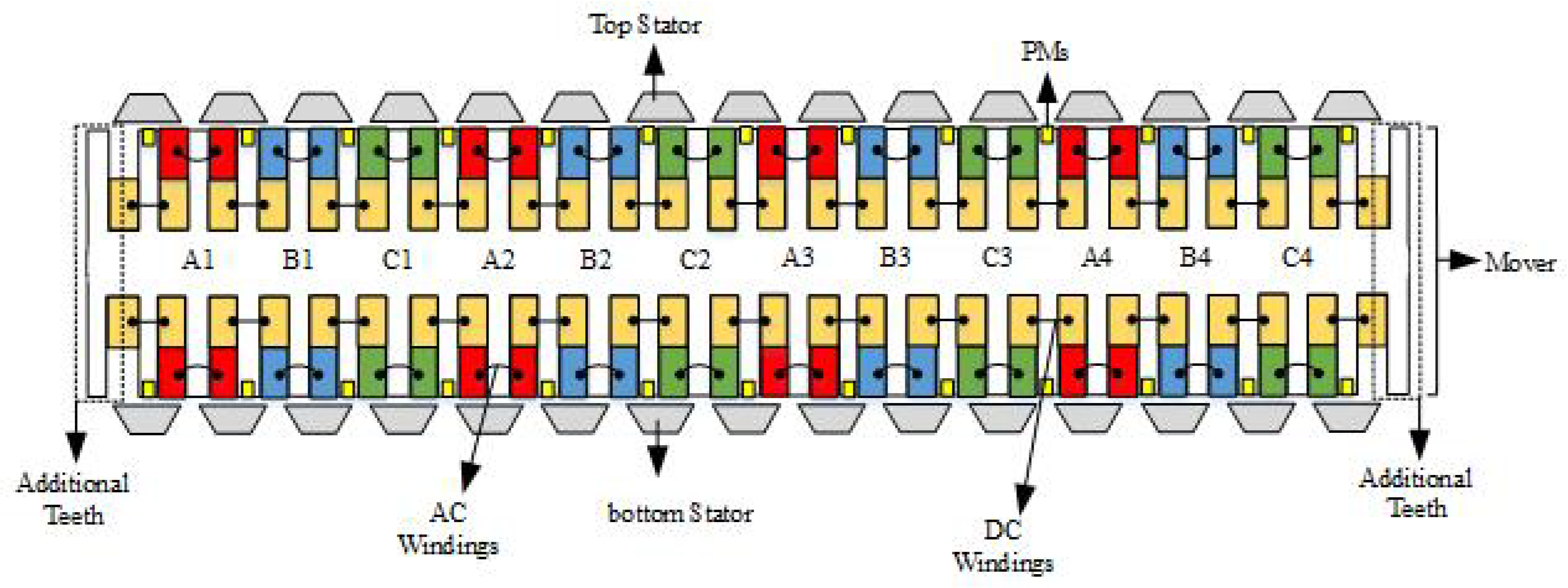
The 2-D schematic diagram of proposed HELFSM.

Figure 4.
Design variables.

Figure 5.
Magnetic circuit based working principle, (a) Positive max. flux linkage, and (b) Negative max. flux linkage.
Figure 5.
Magnetic circuit based working principle, (a) Positive max. flux linkage, and (b) Negative max. flux linkage.

Figure 6.
Optimization of HELFSM: (a) split ratio, (b) slot area dimensions, (c) PM dimensions, (d) unequal tooth width, (e) stator segment tip width, and (f) stator segment base width.
Figure 6.
Optimization of HELFSM: (a) split ratio, (b) slot area dimensions, (c) PM dimensions, (d) unequal tooth width, (e) stator segment tip width, and (f) stator segment base width.

Figure 7.
On-load magnetic flux lines: (a) equal primary tooth width and (b) unequal primary tooth width.
Figure 7.
On-load magnetic flux lines: (a) equal primary tooth width and (b) unequal primary tooth width.

Figure 8.
No-load flux linkage comparison: (a) waveforms and (b) frequency spectrum.

Figure 9.
Detent force comparison.

Figure 10.
Thrust force comparison.

Figure 11.
Average thrust force and power versus variable armature current density.

Figure 12.
Average thrust force and power versus velocity.

Figure 13.
HELFSM prototype and test bed.

Figure 14.
No-load induced B-EMF at 1.5 m/s.

Figure 15.
Detent force comparison.


Table 1.
Structure design parameters.
| Symbol | Parameter (Unit) | Initial Value | Optimized Value |
|---|---|---|---|
| Stator pole pitch (mm) | 30 | ||
| Mover pole pitch (mm) | 35 | ||
| Mover height (mm) | 85 | 91 | |
| Mover DC tooth width (mm) | 7.5 | 9.5 | |
| Stator height (mm) | 25 | 19 | |
| Slot width (mm) | 10 | 8.5 | |
| Mover AC tooth width (mm) | 7.5 | 8.5 | |
| Slot height (mm) | 17.5 | 20.6 | |
| Mover yoke height (mm) | 15 | 8.6 | |
| PM width (mm) | 5 | 7 | |
| PM height (mm) | 5 | 3.5 | |
| PM volume (grams) | 45.5 | 45.5 | |
| Stator segment tip width (mm) | 24 | 28.5 | |
| Stator segment height (mm) | 12.5 | 9.5 | |
| Stator segment base width (mm) | 12 | 12.825 | |
| L | Stack length (mm) | 10 | |
| g | Air-gap height (mm) | 2 | |
| v | Mover velocity (m/s) | 1.5 | |
| DC current density (A/mm) | 4.52 | ||
| AC current density (A/mm) | 4.57 | ||
| Number of AC and DC coil turns | 40 | ||
Table 2.
Optimization process.
| Coefficients (Symbol) | Definition | Initial Value | Constraints | Optimized Value |
|---|---|---|---|---|
| Split Ratio | 0.254 | (0.20–0.34) | 0.201 | |
| Slot area | 0.571 | (0.36–0.82) | 0.412 | |
| dimensions | ||||
| PM dimensions | 1.0 | (0.16–2.0) | 2.0 | |
| Unequal tooth | 1.0 | (0.71–1.0) | 0.894 | |
| width | ||||
| Stator segment | 0.8 | (0.60–0.95) | 0.95 | |
| tip width | ||||
| Stator segment | 0.5 | (0–0.50) | 0.45 | |
| base width | ||||
Table 3.
Optimization results and comparisons.
| Performance Indicator (Unit) | Excitation | Initial Value | Optimized Value |
|---|---|---|---|
| Flux Linkage | PM | 4.88 | 7.41 |
| (mWb) | |||
| THD | 8.62 | 1.48 | |
| Detent Force | 1739.05 | 1359.34 | |
| (N) | |||
| Thrust Force | 4472.19 | 6915.87 | |
| (N) | |||
| TFRR | 40.94 | 19.27 | |
| Flux Linkage | FEC | 3.20 | 3.45 |
| (mWb) | |||
| THD | 2.03 | 1.88 | |
| Detent Force | 133.32 | 216.61 | |
| (N) | |||
| Thrust Force | 3202.39 | 3483.92 | |
| (N) | |||
| TFRR | 10.85 | 13.87 | |
| Flux Linkage | PM+FEC | 8.10 | 10.90 |
| (mWb) | |||
| THD | 4.76 | 1.17 | |
| Detent Force | 2338.65 | 1028.83 | |
| (N) | |||
| Thrust Force | 7581.32 | 10111.13 | |
| (N) | |||
| TFRR | 30.71 | 9.15 |
Publisher’s Note: MDPI stays neutral with regard to jurisdictional claims in published maps and institutional affiliations. |
© 2021 by the authors. Licensee MDPI, Basel, Switzerland. This article is an open access article distributed under the terms and conditions of the Creative Commons Attribution (CC BY) license (https://creativecommons.org/licenses/by/4.0/).
Share and Cite
MDPI and ACS Style
Ullah, N.; Khan, F.; Basit, A.; Shahzad, M. Experimental Validations of Hybrid Excited Linear Flux Switching Machine. Energies 2021, 14, 7274. https://doi.org/10.3390/en14217274
AMA Style
Ullah N, Khan F, Basit A, Shahzad M. Experimental Validations of Hybrid Excited Linear Flux Switching Machine. Energies. 2021; 14(21):7274. https://doi.org/10.3390/en14217274
Chicago/Turabian StyleUllah, Noman, Faisal Khan, Abdul Basit, and Mohsin Shahzad. 2021. "Experimental Validations of Hybrid Excited Linear Flux Switching Machine" Energies 14, no. 21: 7274. https://doi.org/10.3390/en14217274
Note that from the first issue of 2016, this journal uses article numbers instead of page numbers. See further details here.