
Finite Element Analysis of Tidal Turbine Blade Subjected to Impact Loads from Sea Animals †


School of Engineering, The University of Edinburgh, Edinburgh EH9 3FG, UK
*
Author to whom correspondence should be addressed.
†
This paper is an extended version of our paper published in The 2021 World Congress on Advances in Structural Engineering and Mechanics (ASEM21), GECE, Seoul, Korea, 23–26 August 2021.
Energies 2021, 14(21), 7208; https://doi.org/10.3390/en14217208
Submission received: 4 October 2021
/
Revised: 25 October 2021
/
Accepted: 28 October 2021
/
Published: 2 November 2021
(This article belongs to the Collection Women's Research in Wind and Ocean Energy)
Abstract
:The present work investigates structural response of tidal stream turbine blades subjected to impact loads from sea animals. A full-scale tidal turbine blade model was developed using a finite element modelling software ABAQUS, while a simplified geometry of an adult killer whale (Orcinus orca) was assumed in simulating impact on the blade. The foil profiles along the turbine blade were based on the NACA 63-8XX series, while the geometric and material properties of the sea animal were calibrated with experimental results. The numerical model simulated the dynamic response of the blade, accounting for radial velocities of the blade corresponding to real life scenarios. Different magnitudes and trajectories of the velocity vector of the sea animal were simulated, in order to investigate their influence on the turbine blade’s plastic deformation. Furthermore, multiple impacts were analysed, in order to monitor the accumulation of plastic strain in the material of the blade. Finally, the potential application of stainless steel material in tidal stream turbine blades for impact resistance was evaluated, through comparison of numerical results obtained from models using stainless steel and mild carbon steel materials.
1. Introduction
Global demand for clean energy production is constantly increasing, aiming to replace fossil fuels consumption. Wind and solar energy technologies have been developed extensively during the last decades, while oceans could also offer huge amounts of sustainable energy [1]. Plenty of technologies and devices have been developed to produce power from waves and ocean thermal currents. Furthermore, tidal currents complement the ocean renewable energy resources. In recent years, there has been a rapid development in this direction, due to its advantage of predictable and stable energy output, compared with the rest offshore renewable resources. Many devises have been examined for tidal current energy conversion; they are divided between vertical axis current turbines (VACTs) [2] and horizontal axis current turbines (HACTs) [1,3], which constitute the majority of tidal turbine devices. This type of turbine is also known as marine current turbine (MCT) [4,5].
The most common configuration for a tidal turbine device is a three-bladed horizontal axis turbine. Accounting for this configuration, several experimental and numerical studies have been conducted, in order to investigate the power generation and thrust of marine current turbines. Extensive experimental investigation of a horizontal axis turbine in a towing tank and in a cavitation have been conducted by Bahaj et al. [6], investigating the characteristics of turbine power and thrust of a small-cale NACA 63-8XX series blade under different operation conditions, such as RPM range, flow speed and hub pitch angle. In addition, numerical results have been reported by Bahaj et al. [7] and Batten et al. [8], calculating the characteristics of the aforementioned blade geometry, based on blade element momentum (BEM) theory [9]; while Ellis et al. [10] applied BEM, three-dimensional computational fluid dynamics (CFD) and experimental tests to identify the characteristics of an in-house blade geometry (FX63-137). More recently, a detailed experimental work was presented by Payne et al. [11], describing the manufacturing process and the instrumentation of a small-scale tidal turbine model with NACA 63-8XX series blades, measuring the peak loads, due to combined turbulent flow and waves.
The constantly increasing need of electricity generation from tidal turbines leads to application of turbines in long rows normal to the mean flow direction or in multiple rows, such as arrays. These configurations of turbines have shown to affect significantly the hydrodynamic characteristics, development and interaction of the wake field of tidal current turbines within the array [12,13,14]. Pintar and Kolios [15] presented an experimental facility, accounting for a vessel with its own propulsion, carrying arrays of horizontal axis tidal turbines. The interaction of the turbines was investigated using computational fluid dynamics (CFD), considering different configurations of the turbines, while a numerical model was also developed simulating the structural response of the testing facility. More recently, Gillibrand et al. [16] investigated numerically the influence of the number of tidal turbine devices used in arrays on near-bed velocity and local shear stress, which is a key parameter in the erosion of seabed sediment.
Furthermore, as the tidal blades are placed underwater, another problem associated with impact damage from large debris and sea animals arises with the increased number of turbine blades [17]. Payne et al. [18] conducted preliminary small-scale impact tests, investigating the peak loading on a variety of materials with similar properties with the skin, bones and flesh of sea animals. Furthermore, Grear and Motley [19], Copping et al. [20] and Grear [21] performed extensive experimental tests to characterize the material properties of tissues, based on different kinds of marine mammals, and presented numerical results to identify the damage on the sea animal, using geometrically simplified tidal turbine blades and sea animals. Additionally, Hammar et al. [22] presented a probabilistic model, quantifying the collision risk of small-sized and large-sized fish at large turbines, considering rotors with diameter greater than 5 m, while Onoufriou et al. [23] investigated the potential severe trauma on seal carcasses (Halichoerus grypus), using a replica of turbine blade made of PVC, identifying soft tissue damage with respect the different velocities of the blade.
More specifically, Grear [21] conducted experimental and numerical work investigating the bio-mechanical properties of four different marine mammals, such as harbour porpoise (Phocoena phocoena), Southern Resident killer whale or “SRKW” (Orcinus orca), Dall’s porpoise (Phocoenoides dalli), and harbour seal (Phoca vitulina). The present investigation focuses on the impact resistance of tidal turbine blades with a sea animal and more specifically with a killer whale (Orcinus orca). A killer whale is characterized by white and black markings, while above and behind the eye of each side of the whale, an elliptically shaped white patch is observed, which is also referred to as “eye-patch”. The shape of the sea animal is similar to a large dolphin, while its size varies from 6.5 m to 9 m long and it weights from 4700 kg to 6600 kg, depending on the gender and the age. Pitman and Ensor [24] and Pitman et al. [25] described in detail three different types of killer whales, identifying differences in colouration, morphology, and apparent dietary specialization, while the general characteristics of the killer whales, behaviour, sound production and interaction with other species are summarized by Ford [26].
In general, the majority of the tidal turbine blades are made of carbon steel materials [27,28], which leads to increased maintenance costs. Furthermore, tidal turbine blades made of mild carbon steel material also suffer from corrosion, due to the high salinity environment. Therefore, the present work focuses on the dynamic response of a tidal turbine blade made of stainless steel, which is a corrosion resistant material, subjected to impact loading by a killer whale, while this is a extension of preliminary results presented by the authors [29]. In addition, investigation on impact resistance of turbine blade with stainless steel material and mild carbon steel is performed. The influence of different magnitudes and trajectories of the velocity vector of the sea animal is investigated, identifying its influence on plastic deformation of the turbine blade. The numerical results are compared with theoretical results obtained from the corresponding analyses considering carbon steel material. The effect of multiple impacts on the plastic strain accumulation is also presented.
2. Geometry and Numerical Modelling
2.1. Tidal Turbine Blade
In the present study, the turbine blade profiles were determined based on the NACA 63-8XX series, which is commonly used in tidal turbine devices. A full-scale blade was assumed, considering ten foil profiles with the geometric characteristics, as presented by Payne et al. [11] and scaled up by fifteen to obtain the full-scale geometry. Table 1 presents the thickness (t), chord (c), radial location (r), and twist of each foil profile along the m rotor, while the profile at is presented in Figure 1 for a better visualization of the foil profiles. The shape of each of the ten foil profiles was obtained using the JavaFoil software [30], which provided the plane coordinates of each foil based on its and ratios. Subsequently, the coordinates were rotated following the twist angle, as described in Table 1, while the centre of rotation is located at one quarter from the leading edge, as shown in Figure 1. This point corresponds approximately to the aerodynamic center of each foil profile [31]. Then, the coordinates of each profile was imported in a CAD software [32] at the appropriate radial location (parameter r in Table 1), with the axis of the blade going through the centre of rotation of each foil profile. In the following, interpolated smooth curves were generated, using the discrete point of each foil profile, while these smooth curves were used for an interpolated lofted surface. For the sake of completeness, the leading edge of an airfoil profile is its foremost edge, which first meets the upcoming fluid separating its flow lines, while the trailing edge is the rear edge of an aerodynamic surface, where the fluid separated by the leading edge meets [33], as presented in Figure 1.
Figure 2 presents a three-dimensional model of a NACA 63-8XX blade created in SolidWorks [32] and then imported in commercial package ABAQUS [34]. The blade was considered as a cantilever. The profiles from r equal zero to r equal to were fixed, following the experimental set-up presented by Bahaj et al. [6], restraining all the displacements and rotations, while the other end is free. The blade was modelled using 83,965 C3D10HS elements. This type of general-purpose quadratic tetrahedron element provides superior stress visualization and exhibits improved convergence simulating contact and metal plasticity, based on the documentation of ABAQUS [34]. The mesh is denser around the region where contact was established with the sea animal to overcome convergence issues.
Furthermore, stainless steel material of Grade 304 was adopted for the tidal blade, which is widely used in construction applications. Stainless steel of Grade 304 (or in European norm) has excellent corrosion resistance and is highly ductile, as described in previous works [35,36,37]. Due to the nature of the problem, the Johnson and Cook [38] constitutive model was employed in the simulations, which includes strain hardening, strain rate phenomena and temperature effects. According to Johnson and Cook constitutive model, the flow stress () is described by the following expression:
where and are equivalent plastic strain and equivalent plastic strain rate, respectively.
The material properties for the 304 stainless steel material are presented in Table 2, where A, B, n, c, and m are Johnson–Cook parameters obtained by fitting to experimental curves, as reported by Lee et al. [39]. More specifically, parameter A is the initial yield strength of the material at quasi-static strain rate, B and n represents the flow stress on strain hardening behaviour at quasi-static strain rate, T is the material temperature, is the room temperature, and is the melting temperature of the material, while C and m represent strain rate effect and thermal softening effect, respectively.
2.2. Killer Whale (Orcinus orca)
The killer whale was modelled using a simplified geometry considering a solid cylinder, as shown in Figure 2. The diameter of the model is m, and it was based on the maximum diameter of the model presented by Carlson et al. [17]. The length () is equal to m, which was determined in order to obtain the same volume with the model used by Carlson et al. [17]. Furthermore, the model was divided into three sections, assigning the corresponding material properties in each one, representing a bone in the core of the model, surrounded by blubber and followed by skin, as shown in Figure 2. The diameter of the bone () is equal to m; the diameter of the blubber () equals m, while their ratio with the total diameter of the model is similar to the numerical model presented by Carlson et al. [17]. The geometrical characteristics of the numerical model of the killer whale are also summarized in Table 3.
An isotropic elastic material was assumed for the bone. The Young’s modulus and the Poisson’s ratio of the bone are MPa and , respectively. These are average values obtained from experimental tests, corresponding to cortical bone from right whale jaw bone, as reported in a study conducted by Campbell–Malone [40]. For the blubber and the skin, experimental data were imported in ABAQUS, which have been reported by Grear [21]. Considering the experimental data, hyperelastic constitutive models were employed to describe their structural response, due to incompressibility of the soft tissues of the sea animal, such as in case of rubber materials, following the experimental and numerical approach described in previous works [17,18,21]. Using the experimental data, ABAQUS can fit several built-in hyperelastic constitutive models providing the corresponding coefficients. For the blubber, the reduced Polynomial constitutive model [41] was considered, where the elastic properties of the material may be described in terms of the following strain energy function:
where are the material constants that describe the shear behaviour and they can be determined from laboratory testing, D controls the compressibility of the material, which could be zero if the material is fully incompressible, J is the elastic volume ratio, N is the number of terms in the energy function, and is the first invariant of the deviatoric strain and is given by the following expression:
The material parameters for the blubber, considering in Equation (2), are kPa, kPa, and . For the skin, the constitutive model proposed by Ogden [42] was used, which is described by the following strain energy potential:
where and are material constants describing the shear behaviour of the material, J is the elastic volume ratio, D controls the compressibility of the material, while parameters depend on the principal stretches () by the following expression:
The material parameters for the skin, considering in Equation (4), are MPa, , and . These sets of parameters were stable for all strains, while the density for each material was considered equal to 1000 kg/m3, as also reported by Grear [21]. During initial stages of numerical modelling, isotropic elastic materials were assumed for the blubber and the skin, such as the bone, following the study presented by Grear and Motley [19], and adopting corresponding Young’s modulus and Poisson’s ratios for both materials. However, excessive distortion of killer whale’s elements and convergence issues were arisen, therefore both materials were considered as hyperelastic materials.
Furthermore, 51,453 quadratic tetrahedral elements of type C3D10HS were employed for the whale, while the surface-to-surface algorithm of ABAQUS was used for the contact during the impact, assuming the blade as the master surface and the outer surface of the skin section as the slave. The friction coefficient used in the simulations is equal to 1 [43]. It should be noted that this value corresponds to friction coefficient between polished stainless steel and human skin, however this value was adopted in the simulations, due to the lack of the corresponding value for killer whale skin.
3. Numerical Results
In the present study, the blade was assumed fixed at the centre of the rotor, while a velocity was applied to the killer whale, impacting the blade. The velocity of the whale was adopted accordingly, in order to have similar initial kinetic energy on the model, such as in a real case scenario during the operation conditions of a full-scale tidal turbine. More specifically, the Reynolds number at the three quarters of the radial span of the blade is in the order of 106 [44] for a full-scale tidal turbine. Therefore, the rotational speed and the corresponding rotational kinetic energy were calculated for the blade, concluding to the translational velocity () of the whale along x-axis, which imposes similar initial kinetic energy to the numerical model.
The velocity of the killer whale was considered in one direction in the present analysis. The velocity magnitude at x-direction is equal to (), while at y and z-direction the velocity is equal to zero (), according to the coordinate system shown in Figure 2. During impact loading, the bending moment at y-direction reaches its maximum value at fixed end of the turbine blade. Therefore, the maximum bending stresses () occur on this foil profile, where the blade is in tension at the leading edge of the section and in compression at the trailing edge, as shown in Figure 3. This figure also shows that the maximum von Mises stress occurs at the trailing edge, indicating the region where plastic deformation might occur during impact.
Upon the contact between the killer whale and the tidal turbine blade is established, the kinetic energy of the model gradually reduces, as shown in Figure 4a, leading to increasing of the deflection of the blade. Figure 4a presents the kinetic energy of the model normalized by the initial kinetic energy, considering translational velocity of the killer whale , with respect of time normalized by the modal period of the first bending mode at x-direction (), which is equal to s. During impact loading, the kinetic energy reduces, reaching a minimum point, which corresponds to the maximum deflection of the blade. Therefore, this point also corresponds to the maximum value of von Mises stress. Figure 4b presents the von Mises stress of the turbine blade at the fixed end foil profile at the trailing edge, normalized by material parameter A of Table 2, which corresponds to the yield stress at quasi-static strain rate of the stainless steel material of Grade 304 (). It is shown that the turbine blade deforms elastically during impact loading, considering velocity at x-direction equal to . This observation is also verified in Figure 4c, where the bending stress and strain at z-direction at the trailing edge of the fixed end foil profile of the blade are presented, showing elastic deformation of the blade.
In addition, higher velocities of the killer whale were considered, investigating the dynamic response of the turbine blade and monitoring their effect on plastic deformation of the stainless steel material. The different velocity ratios , investigated and presented in the current section, are equal to , , , , , , , and . Figure 4a presents the kinetic energy of the numerical model for the different velocities of the killer whale, normalized by the initial kinetic energy for each case, with respect to time normalized by the modal period of the first bending mode at x-direction (). Increasing the velocity of the killer whale, the reduction of the kinetic energy occurs in an earlier stage, reaching the minimum value at the time when the blade reaches its maximum deflection, as shown in Figure 4a,b. The impact load also increases with the increasing velocity of the killer whale, leading to plastic deformation of the stainless steel material at the trailing edge of the profile corresponding to the fixed end of the blade. The von Mises stress also increases with the increasing velocity of the whale, while the material yields for velocities higher than two times the operational velocity , leading to plastic deformation. This is also presented in Figure 4c, showing the compressive stress–strain curve for each killer whale velocity case, and in Figure 4d which presents the equivalent plastic strain () of the trailing edge at the same region, with respect the different normalized velocities of the killer whale at x-direction. For normalized velocities equal to , , and , a very low value of equivalent plastic strain is observed in the tidal turbine blade stainless steel material. However, the % yield offset corresponds to normalized velocity equal to , while increasing the velocity of the sea animal, the plastic deformation of the blade increases exponentially up to 1% approximately. Furthermore, plastic deformation of the turbine blade is observed at the leading edge, where the foil profile is under tension, for normalized velocities equal to , , and . However, higher plastic strain values occur at the trailing edge, due to geometry of this region.
Finally, it is observed that the blade deforms at x-direction, as discussed in the previous paragraphs, considering the one-directional velocity of the sea animal, which is also observed in Figure 5. This figure presents the normalized bending moment () at y-direction at the fixed end of the tidal turbine blade, with respect time normalized by the modal period of the first bending mode at x-direction (), for the different velocities of the killer whale. The bending moment is normalized by , where is the moment of inertia around y-axis. However, the blade also deflects at y-direction, due to the twist of the foil profiles along the turbine blade (shown in Table 1). This observation is verified in Figure 6, which presents the normalized bending moment () at x-direction at the fixed end of the tidal turbine blade, with respect time normalized by the modal period , for the different velocities of the killer whale. The bending moment is one order of magnitude lower compared with with the bending moment at y-direction (). Furthermore, Figure 7 presents the translation (, ) of the centre of rotation of the profile of the blade at radial location equal to , normalized by the chord (c) of the foil profile. The figure presents significant and comparable deflection of the blade at y-direction, while the deflection increases significantly in both directions with increasing the velocity of the killer whale, as expected. This is an important observation, while considering two-dimensional velocity of the killer whale, it might affect the plastic deformation of the blade and the region, which it will occur. Therefore, the aforementioned loading scenario was also investigated in the present study and it is presented in detail in Section 4.3.
4. Parametric Studies Assuming Different Material and Loading Parameters
In the following paragraphs, the effect of several parameters on the dynamic response and the accumulation of plastic strain in the material of the tidal turbine blade was investigated. The influence of the turbines blade’s material on plastic strain accumulation was examined, comparing the results with the case of stainless steel material. In addition, the effect of multiple impacts of the tidal turbine blade with sea animals was investigated, monitoring the hardening of the material and the corresponding plastic strain accumulation. Finally, different trajectories of the killer whale were considered, investigating their influence on the dynamic response of the blade and the region where plastic deformation occurs.
4.1. Carbon Steel Material of Grade AISI 1020
In addition, the dynamic response of tidal turbine blade made of carbon steel was investigated, in order to compare the dynamic response and the accumulation of plastic strain in the blade with the corresponding blade made of stainless steel material. The material properties of the Johnson and Cook [38] constitutive model for the carbon steel material of Grade AISI 1020 were adopted by the work of Bashistakumar and Pushkal [45], and they are summarised in Table 4. Furthermore, one-directional velocity of the killer whale was assumed at x-direction, for normalized velocities () equal to , , , , , , , and , as presented in Section 3.
Figure 8 presents 8a the kinetic energy of the numerical model during impact loading, normalized by the initial kinetic energy for each velocity case, with respect time normalized by the modal period of the first bending mode at x-direction (), 8b the von Mises stress at the trailing edge of the foil profile of the blade at the fixed end, normalized by the yield stress at quasi-static strain rate of AISI 1020 carbon steel (), with respect normalized time, 8c the normal stress at z-direction (), normalized by the yield stress at quasi-static strain rate of the material, with respect to the corresponding normal strain (), and 8d the equivalent plastic strain () for both materials with respect the different velocities of the sea animal at x-direction.
The kinetic energy of the model for each velocity case of the killer whale follows the trend as discussed in Section 3, accounting for stainless steel material of Grade 304. The kinetic energy drops during impact, while the deflection of the blade increases, reaching a minimum point when the maximum deflection of the turbine blade occurs. At that point, which corresponds to the maximum deflection of the blade, the maximum von Mises stress is also observed at the trailing edge of the foil profile at the fixed end of the blade. Beyond that point, the von Mises stress drops and the kinetic energy starts to increase, indicating push-back of the killer whale by the blade. Furthermore, it is shown that higher velocity of the sea animal is required to deform plastically the carbon steel material of the blade. Plastic deformation of the turbine blade, considering carbon steel material of Grade AISI 1020, initiates at normalized velocity () equal to , instead of for the stainless steel material, as shown in Figure 4d in Section 3. In addition, the equivalent plastic strain of the blade made of carbon steel material is 87% lower than the blade with stainless steel material, considering the highest normalized velocity examined in the present work. However, the equivalent plastic strain for the case of stainless steel material is still low. The value is lower than 1%, even for velocity which corresponds to five times higher kinetic energy than the operational conditions assumed in the present study.
4.2. Multiple Impacts
In the present section, the dynamic response and the accumulation of the plastic strain in the tidal turbine blade’s stainless steel material was simulated, considering multiple impacts with sea animals. This is the first approach to investigate the influence of multiple impact events on the accumulation of plastic strain, which could lead to damaging of the material’s microstructure, crack initiation, crack propagation and failure eventually of the turbine blade. For the analyses presented in the present section, the normalized velocity () of the killer whale was assumed to be ; this velocity corresponds to equivalent plastic strain approximately equal to %, which corresponds to the % offset yield point. Furthermore, it was imposed in each impact, the plastic strain of the turbine blade’s stainless steel material simulated in the previous impact event, as initial condition, while forty five impact events were simulated in total.
Figure 9 presents the compression at the trailing edge of the foil profile at the fixed end of the turbine blade for the first ten impacts. The normalized normal stress at z-direction () is shown at the foil profile at the fixed end of the turbine blade, with respect to the corresponding normal strain (), for the increasing number of impact events. The plastic deformation and the corresponding hardening of the stainless steel material during the impact loading, leads to increasing gradually the yield stress of the material. Therefore, the elastic energy which is dissipated into the stainless steel material, in order to reach the increased yield point, resulting in reducing the energy which corresponds to plastic deformation of the material. At this point, it should be noted that the initial energy is similar in every number of impact and corresponds to the initial kinetic energy.
Furthermore, the equivalent plastic strain of the stainless steel material is also shown in Figure 10, with respect to the number of impacts. The figure shows that increasing the number of impacts the material hardens and the corresponding increase of the plastic strain rate decreases. Therefore, increasing the number of impacts and the corresponding hardening of the tidal turbine blade’s material, the velocity of the sea animal and the corresponding initial kinetic energy will result in elastic deformation of the blade exclusively. This is an important correlation between the number of impacts, required to result in elastic deformation of the material, and the initial kinetic energy, while it constitutes an important tool for structural health monitoring (SHM) [46], in order to identify potential damage of the material’s microstructure [47].
4.3. Two-Directional Velocity of the Killer Whale
In the current analysis, the velocity of the killer whale was considered in two dimensions, in order to amplify the deflection of the blade at y-direction and examine the plastic strain accumulation. The normalized velocity magnitude at x-direction () was considered equal to , , , , , , , , , and , such as in Section 3 and Section 4.1, according to coordinate system shown in Figure 2. Considering the geometric characteristics of the tidal turbine blade and the deflection at the negative direction of y-axis, in case of one-directional velocity of the sea animal at x-axis, a component of the killer whale velocity at this direction was applied. The activity states of a killer whale could be divided to “Forage”, which is non-directional swimming to search and locate food indicated by arch dives, “Rest”, including swimming at very low speeds, “Social”, including interaction with other members of the pod, and “Travel”, considering directional movement at a steady pace, as described in detail by Noren et al. [48] and Noren [49]. The speed of the killer whale varies from m/s to m/s for the aforementioned activity states. Therefore, velocity equal to 1 m/s was considered representative and it was applied at the negative direction of y-axis, while the tidal turbine blade was considered as a cantilever, assuming the foil profiles from r equal zero to r equal to fixed. It should also be noted that excessive distortion of the mesh of the killer whale was noticed, using the mesh of the killer whale as described in Section 2.2, leading to convergence issues. During impact the contact region between the turbine blade and the killer whale changes due to component of the velocity vector of the killer whale. Therefore, a denser mesh for the skin of the killer whale was considered around the contact region between the blade and the killer whale, using 178806 C3D10HS elements.
Figure 11 presents the normalized kinetic energy of the numerical model for the different magnitudes of velocity of the killer whale at x-direction, with respect to time normalized by the modal period of the first bending mode at x-direction (). In these analyses, the kinetic energy of the numerical model for each velocity case follows similar trend with the kinetic energy presented in Figure 4a and Figure 8a, where one-directional velocity was applied to the killer whale. Considering the case, where the normalized velocity at x-direction () of the killer whale is equal to 1, the kinetic energy of the model reduces, reaching the lowest value at time where the tidal turbine blade reaches its maximum deflection. However, it is observed that a significant amount of kinetic energy is still stored in the numerical model, due to the fact that the component of the velocity vector of the killer whale at y-axis is higher than the component of velocity vector at x-axis, corresponding also to large amount of kinetic energy compared to the initial kinetic energy of the numerical model. Increasing the magnitude of velocity of the killer whale at x-direction leads to increasing the ratio of the kinetic energy due to the velocity component at x-axis over the total kinetic energy of the numerical model. Therefore, the lowest value of kinetic energy reduces while increasing the velocity at x-direction, due to the fact that the ratio of the kinetic energy due to component of the killer whale over the total kinetic energy reduces.
Considering the two-dimensional deflection of the tidal turbine blade, assuming velocity of the killer whale at x-direction, Figure 12 presents the translation (, ) of the centre of rotation of the profile of the blade at radial location equal to , normalized by the chord (c) of the foil profile, for normalized velocity of the killer whale at x-direction () equal to 1, and , while the component of the velocity vector at y-axis is equal to 1 m/s. Figure 12 shows that the trajectory of the velocity of the killer whale affects significantly the total deflection of the tip of the tidal turbine blade. More specifically, the total deflection of the tip of the blade could be calculated by the following expression:
where the maximum deflection () of the blade for equal to 1, , and equal to zero is , , and , respectively, normalized by the chord (c) of the profile of the blade at radial location equal to . Furthermore, the maximum deflection of the tip of the blade for the same normalized velocities at x-direction and equal to 1 m/s is increased by 163%, 234%, and 85%, respectively. Therefore, the trajectory of the velocity vector of the killer whale affect significantly the deflection the tip of the blade. In this case, considering a representative translational velocity of the sea animal tangent to the rotor results in significantly increased deflection of the tip of the turbine blade at y-direction, which also might affect the plastic deformation of the material of the blade at the fixed end and the region where the maximum value occurs.
Figure 13 presents the equivalent plastic strain () of the stainless steel material of Grade 304 for one and two-directional velocity of the killer whale, for different normalized velocities at x-direction (). In case where the component of the velocity vector of the killer whale at y-axis is zero, a stress distribution is observed at the foil profile of the blade at the fixed end. It is shown that the blade is under tension at the leading edge and in compression at the trailing edge, while due to the geometric characteristics of the trailing edge, the tidal turbine blade deforms plastically at this region increasing the velocity () of the killer whale; the structural performance of the blade under these conditions is described in more detail in Section 3 and Section 4.1.
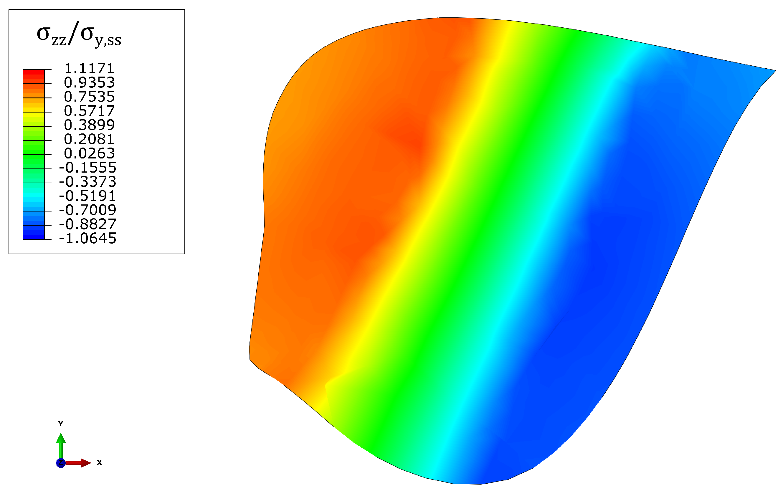
However, in case of two-dimensional velocity of the killer whale, the foil profile at the fixed end of the blade is in tension at the leading edge and at the upper surface, and in compression at the training edge and at the lower surface of the foil profile, as shown in Figure 14. Considering low values of the component of the velocity vector at x-axis, the turbine blade initially deforms plastically at the upper surface near to the leading edge, as indicated schematically in Figure 14, due to superposition of the two aforementioned stress distributions along the chord and the thickness of the foil profile. The superposition of the two bending stress () distributions of the foil profile at the fixed end, which are from leading edge to trailing edge and from upper surface to lower surface, are also observed in Figure 15, for the case of normalized velocity of the sea animal at x-direction () equal to . However, excessive compression is observed at the trailing edge of the foil profile, increasing the component at x-axis of the velocity vector of the killer whale, which leads to plastic deformation, as presented in Figure 13. Therefore, the trajectory of the velocity vector of the sea animal and the magnitude of the vector influences the two aforementioned stress distributions, affecting the region where plastic deformation of the turbine blade occurs.
5. Conclusions
In the present work, a full-scale tidal turbine blade was modelled, investigating its dynamic response under impact loading with an adult killer whale. Stainless steel material of Grade 304 was considered for the tidal turbine blade, attempting to evaluate its impact resistance, while its dynamic response was compared with mild carbon steel material, which is most commonly used. The blade was assumed fixed at the centre of the rotor, while velocity was applied to the killer whale. The velocity of the sea animal () was adopted accordingly, in order to have similar initial kinetic energy on the model, such as in a real case scenario during the operation conditions of a full-scale tidal turbine. It should be noted that the following conclusions are based on the geometric and material properties of the killer whale adopted in the present study. Different age of the killer whale or species might affect the material properties and the dynamic response of the tidal blade.
Considering velocity of the sea animal equal to , which corresponds to operational conditions of the full-scale tidal turbine, the turbine blade deforms elastically. However, applying velocities higher than two times of , plastic deformation of the blade at the centre of the rotor was observed. It is also important to note that the blade deflects at x-direction, which corresponds o the direction of the killer whale’s velocity, and also at y-direction due to the twist of the foil profiles along the turbine blade. Based on this observation, additional analyses were performed, considering different trajectories of the velocity vector of the killer whale, in order to amplify the deflection of the blade at y-direction. The results show that the trajectory of the velocity vector of the sea animal and the magnitude of the vector influences significantly the stress distribution from the leading edge to trailing edge and from the upper surface to the lower surface, which also affects the region where plastic deformation of the turbine blade occurs.
Furthermore, the dynamic response and the accumulation of plastic deformation in the stainless steel material of the blade was compared with a blade made of carbon steel, for different velocities of the killer whale. Assuming AISI 1020 carbon steel material, the blade deformed plastically in higher velocity magnitudes of the sea animal, compared with the case of stainless steel material of Grade 304. Therefore, the values of equivalent plastic are lower for the carbon steel material strain in the same range of velocities of the killer whale. However, the stainless steel material constitutes a promising material for such a device, considering the reduced maintenance costs, the corrosion resistance and the elastic deformation of the blade for the assumed operational conditions; the blade deforms plastically in a significantly higher sea animal velocity.
Finally, in case of multiple impacts, the material of the turbine blade hardens leading to reducing the rate of the plastic strain increase. Simulating forty five consecutive impacts, the equivalent plastic strain in the turbine blade’s material is slightly higher than %, concluding that the turbine blade is well before its ultimate strength, considering the high ductility of the stainless steel material. However, the accumulation of plastic strain in the blade due to multiple impacts is an open issue for further examination, which constitutes an important tool for structural health monitoring, in order to identify potential damage of the material’s microstructure.
Author Contributions
Conceptualization, I.G. and Y.H.; methodology, I.G. and Y.H.; software, I.G.; validation, I.G.; formal analysis, I.G.; investigation, I.G. and Y.H.; resources, I.G.; data curation, I.G. and Y.H.; writing—original draft preparation, I.G.; writing—review and editing, I.G. and Y.H.; supervision, Y.H.; project administration, Y.H.; funding acquisition, Y.H. All authors have read and agreed to the published version of the manuscript.
Funding
This research was funded by Centre for Advanced Materials for Renewable Energy Generation, EPSRC (Grant Ref: EP/P007805/1).
Institutional Review Board Statement
Not applicable.
Informed Consent Statement
Not applicable.
Conflicts of Interest
The authors declare no conflict of interest.
Abbreviations
| AISI | American Iron and Steel Institute |
| BEM | Blade Element Momentum |
| CAD | Computer-Aided Design |
| CFD | Computational Fluid Dynamics |
| HACTs | Horizontal Axis Current Turbines |
| MCT | Marine Current Turbine |
| NACA | National Advisory Committee for Aeronautics |
| PVC | Polyvinyl Chloride |
| RPM | Rounds Per Minute |
| SHM | Structural Health Monitoring |
| SRKW | Southern Resident Killer Whale |
| VACTs | Vertical Axis Current Turbines |
References
- Day, A.H.; Babarit, A.; Fontaine, A.; He, Y.P.; Kraskowski, M.; Murai, M.; Penesis, I.; Salvatore, F.; Shin, H.K. Hydrodynamic modelling of marine renewable energy devices: A state of the art review. Ocean. Eng. 2015, 108, 46–69. [Google Scholar] [CrossRef] [Green Version]
- Ponta, F.L.; Jacovkis, P.M. Marine-current power generation by diffuser-augmented floating hydro-turbines. Renew. Energy 2008, 33, 665–673. [Google Scholar] [CrossRef]
- Ng, K.W.; Lam, W.H.; Ng, K.C. 2002–2012: 10 Years of Research Progress in Horizontal-Axis Marine Current Turbines. Energies 2013, 6, 1497–1526. [Google Scholar] [CrossRef] [Green Version]
- Fraenkel, P.L. Power from marine currents. Proc. Inst. Mech. Eng. Part A J. Power Energy 2002, 216, 1–14. [Google Scholar] [CrossRef]
- Commission of the European Communities, DGXII. Wave Energy Project Results: The Exploitation of Tidal Marine Currents; Report EUR16683EN; Commission of the European Communities: Brussels, Belgium, 1996. [Google Scholar]
- Bahaj, A.S.; Molland, A.F.; Chaplin, J.R.; Batten, W.M.J. Power and thrust measurements of marine current turbines under various hydrodynamic flow conditions in a cavitation tunnel and a towing tank. Renew. Energy 2007, 32, 407–426. [Google Scholar] [CrossRef]
- Bahaj, A.S.; Batten, W.M.J.; McCann, G. Experimental verifications of numerical predictions for the hydrodynamic performance of horizontal axis marine current turbines. Renew. Energy 2007, 32, 2479–2490. [Google Scholar] [CrossRef]
- Batten, W.M.J.; Bahaj, A.S.; Molland, A.F.; Chaplin, J.R. Hydrodynamics of marine current turbines. Renew. Energy 2006, 31, 249–256. [Google Scholar] [CrossRef] [Green Version]
- Barnsley, M.J.; Wellicome, J.F. Wind tunnel investigation of stall aerodynamics for a 1.0 m horizontal axis rotor. J. Wind Eng. Ind. Aerodyn. 1992, 39, 11–21. [Google Scholar] [CrossRef]
- Ellis, R.; Allmark, M.; O’Doherty, T.; Mason-Jones, A.; Ordonez-Sanchez, S.; Johannesen, K.; Johnstone, C. Design process for a scale horizontal axis tidal turbine blade. In Proceedings of the 4th Asian Wave and Tidal Energy Conference, Taipei, Taiwan, 9–13 September 2018. [Google Scholar]
- Payne, G.S.; Stallard, T.; Martinez, R. Design and manufacture of a bed supported tidal turbine model for blade and shaft load measurement in turbulent flow and waves. Renew. Energy 2017, 107, 312–326. [Google Scholar] [CrossRef]
- Hou, E.; Du, M.; Jiang, B.; Han, L.; Wu, G.; Wang, X. Study on characteristics of turbine wake and the effect of different array arrangement. In Proceedings of the Institution of Civil Engineers—Maritime Engineering; ICE: London, UK, 2021; pp. 1–12. [Google Scholar]
- Olczak, A.; Stallard, T.; Feng, T.; Stansby, P.K. Comparison of a RANS blade element model for tidal turbine arrays with laboratory scale measurements of wake velocity and rotor thrust. J. Fluids Struct. 2016, 64, 87–106. [Google Scholar] [CrossRef]
- Funke, S.W.; Farrell, P.E.; Piggott, M.D. Tidal turbine array optimisation using the adjoint approach. Renew. Energy 2014, 63, 658–673. [Google Scholar] [CrossRef]
- Pintar, M.; Kolios, A.J. Design of a Novel Experimental Facility for Testing of Tidal Arrays. Energies 2013, 6, 4117–4133. [Google Scholar] [CrossRef]
- Gillibrand, P.A.; Walters, R.A.; McIlvenny, J. Numerical Simulations of the Effects of a Tidal Turbine Array on Near-Bed Velocity and Local Bed Shear Stress. Energies 2016, 9, 852. [Google Scholar] [CrossRef] [Green Version]
- Carlson, T.J.; Elster, J.L.; Jones, M.E.; Watson, B.E.; Copping, A.E.; Watkins, M.L.; Jepsen, R.A.; Metzinger, K. Assessment of Strike of Adult Killer Whales by an OpenHydro Tidal Turbine Blade; Technical Report; Pacific Northwest National Lab. (PNNL): Richland, WA, USA, 2012. [Google Scholar]
- Payne, G.S.; Stallard, T.; Martinez, R. Experimental Investigation of Tidal Rotor Loading due to Wave, Current and Impact with Sea Animals. In Proceedings of the 11th European Wave and Tidal Energy Conference, Nantes, France, 6–11 September 2015; pp. 1–9. [Google Scholar]
- Grear, M.E.; Motley, M.R. Numerical Modeling of the Impact Response of Tidal Devices and Marine Mammals. In Proceedings of the 11th European Wave and Tidal Energy Conference, Nantes, France, 6–11 September 2015. [Google Scholar]
- Copping, A.; Grear, M.; Jepsen, R.; Chartrand, C.; Gorton, A. Understanding the potential risk to marine mammals from collision with tidal turbines. Int. J. Mar. Energy 2017, 19, 110–123. [Google Scholar] [CrossRef]
- Grear, M. Characterization of Marine Mammal Biomechanics to Evaluate Tidal Turbine Collision Impact. Ph.D. Thesis, University of Washington, Seattle, WA, USA, 2018. [Google Scholar]
- Hammar, L.; Eggertsen, L.; Andersson, S.; Ehnberg, J.; Arvidsson, R.; Gullström, M.; Molander, S. A Probabilistic Model for Hydrokinetic Turbine Collision Risks: Exploring Impacts on Fish. PLoS ONE 2015, 10, e0117756. [Google Scholar] [CrossRef] [Green Version]
- Onoufriou, J.; Brownlow, A.; Moss, S.; Hastie, G.; Thompson, D. Empirical determination of severe trauma in seals from collisions with tidal turbine blades. J. Appl. Ecol. 2019, 56, 1712–1724. [Google Scholar] [CrossRef]
- Pitman, R.L.; Ensor, P. Three different forms of killer whales in Antarctic waters. J. Cetacean Res. Manag. 2003, 5, 131–139. [Google Scholar]
- Pitman, R.L.; Perryman, W.L.; LeRoi, D.; Eilers, E. A dwarf form of killer whale in Antarctica. J. Mammal. 2007, 88, 43–48. [Google Scholar] [CrossRef]
- Ford, J.K.B. Killer Whale: Orcinus orca. In Encyclopedia of Marine Mammals, 2nd ed.; Perrin, W.F., Würsig, B., Thewissen, J.G.M., Eds.; Academic Press: London, UK, 2009; pp. 650–657. [Google Scholar]
- Douglas, C.A.; Harrison, G.P.; Chick, J.P. Life cycle assessment of the Seagen marine current turbine. Proc. Inst. Mech. Eng. Part M J. Eng. Marit. Environ. 2008, 222, 1–12. [Google Scholar] [CrossRef] [Green Version]
- Shiekh Elsouk, M.N.; Santa Cruz, A.; Guillou, S. Review on the characterization and selection of the advanced materials for tidal turbine blades. In Proceedings of the 7th International Conference on Ocean Energy, Cherbourg, France, 12–14 June 2018. [Google Scholar]
- Gavriilidis, I.; Huang, Y. Dynamic response of tidal turbine blade under impact load. In Proceedings of the 2021 World Congress on Advances in Structural Engineering and Mechanics (ASEM21), GECE, Seoul, Korea, 23–26 August 2021. [Google Scholar]
- Hepperle, M. JAVAFOIL User’s Guide. Available online: https://www.mh-aerotools.de/airfoils/jf_users_manual.htm (accessed on 25 October 2021).
- Abbott, I.H.; Von Doenhoff, A.E. Theory of Wing Sections; Dover Publications: New York, NY, USA, 1959. [Google Scholar]
- Dassault Systèmes. SolidWorks. Available online: https://www.3ds.com/prod./solidworks/ (accessed on 25 October 2021).
- Anderson, J.D., Jr. Fundamentals of Aerodynamics; McGraw-Hill Education: New York, NY, USA, 2010. [Google Scholar]
- Hibbitt, H.; Karlsson, B.; Sorensen, P. Abaqus Analysis User’s Manual Version 2016; Dassault Systèmes Simulia Corp: Providence, RI, USA, 2016. [Google Scholar]
- Baddoo, N.R. Stainless steel in construction: A review of research, applications, challenges and opportunities. J. Constr. Steel Res. 2008, 64, 1199–1206. [Google Scholar] [CrossRef]
- Gedge, G. Structural uses of stainless steel—Buildings and civil engineering. J. Constr. Steel Res. 2008, 64, 1194–1198. [Google Scholar] [CrossRef]
- Rossi, B. Discussion on the use of stainless steel in constructions in view of sustainability. Thin-Walled Struct. 2014, 83, 182–189. [Google Scholar] [CrossRef] [Green Version]
- Johnson, G.R.; Cook, W.H. Fracture characteristics of three metals subjected to various strains, strain rates, temperatures and pressures. Eng. Fract. Mech. 1985, 21, 31–48. [Google Scholar] [CrossRef]
- Lee, S.; Barthelat, F.; Hutchinson, J.W.; Espinosa, H.D. Dynamic failure of metallic pyramidal truss core materials—Experiments and modeling. Int. J. Plast. 2006, 22, 2118–2145. [Google Scholar] [CrossRef]
- Campbell-Malone, R.P. Biomechanics of North Atlantic Right Whale Bone: Mandibular Fracture as a Fatal Endpoint for Blunt Vessel-Whale Collision Modeling. Ph.D. Thesis, Massachusetts Institute of Technology, Cambridge, MA, USA, 2007. [Google Scholar]
- Yeoh, O.H. Some forms of the strain energy function for rubber. Rubber Chem. Technol. 1993, 66, 754–771. [Google Scholar] [CrossRef]
- Ogden, R.W. Large deformation isotropic elasticity—On the correlation of theory and experiment for incompressible rubberlike solids. Proc. R. Soc. Lond. A Math. Phys. Sci. 1972, 326, 565–584. [Google Scholar] [CrossRef]
- Asserin, J.; Zahouani, H.; Humbert, P.; Couturaud, V.; Mougin, D. Measurement of the friction coefficient of the human skin in vivo: Quantification of the cutaneous smoothness. Colloids Surf. B Biointerfaces 2000, 19, 1–12. [Google Scholar] [CrossRef]
- Whelan, J.I.; Stallard, T. Arguments for modifying the geometry of a scale model rotor. In Proceedings of the 9th European Wave and Tidal Energy Conference (EWTEC2011), Southampton, UK, 5–9 September 2011. [Google Scholar]
- Bashistakumar, M.; Pushkal, B. Finite element analysis of orthogonal cutting forces in machining AISI 1020 steel by using a carbide tip tool. J. Eng. Sci. 2018, 5, A1–A10. [Google Scholar] [CrossRef]
- Worden, K.; Farrar, C.R.; Manson, G.; Park, G. The fundamental axioms of structural health monitoring. Proc. R. Soc. A Math. Phys. Eng. Sci. 2007, 463, 1639–1664. [Google Scholar] [CrossRef]
- Li, D.; Ho, S.C.M.; Song, G.; Ren, L.; Li, H. A review of damage detection methods for wind turbine blades. Smart Mater. Struct. 2015, 24, 033001. [Google Scholar] [CrossRef]
- Noren, D.P.; Johnson, A.H.; Rehder, D.; Larson, A. Close approaches by vessels elicit surface active behaviors by southern resident killer whales. Endanger. Species Res. 2009, 8, 179–192. [Google Scholar] [CrossRef]
- Noren, D.P. Estimated field metabolic rates and prey requirements of resident killer whales. Mar. Mammal Sci. 2011, 27, 60–77. [Google Scholar] [CrossRef] [Green Version]
Figure 1.
Graphical representation of the foil profile at radial location [29].
Figure 1.
Graphical representation of the foil profile at radial location [29].
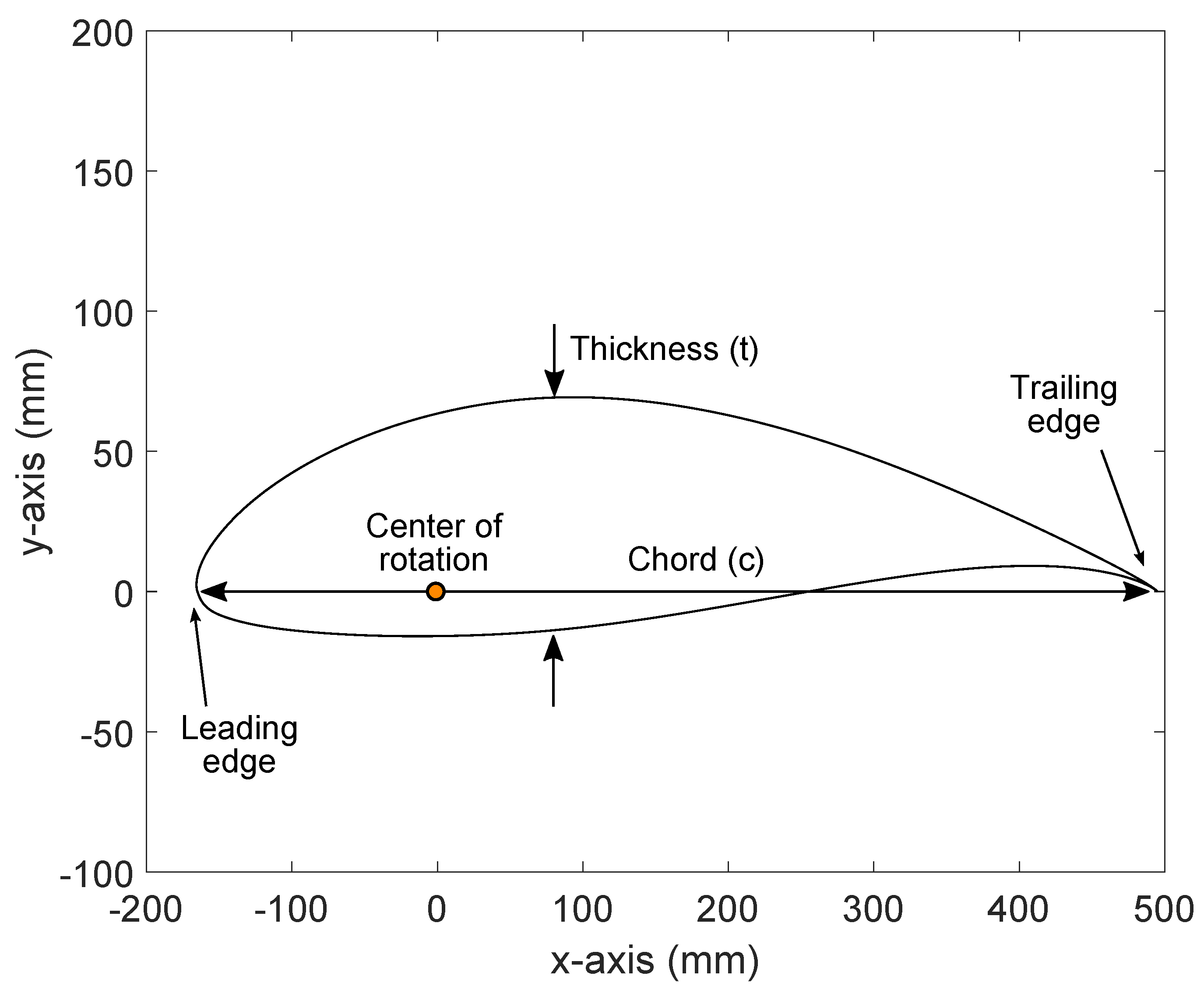
Figure 2.
Visualization of the NACA 63-8XX blade-killer whale finite element model [29].
Figure 2.
Visualization of the NACA 63-8XX blade-killer whale finite element model [29].
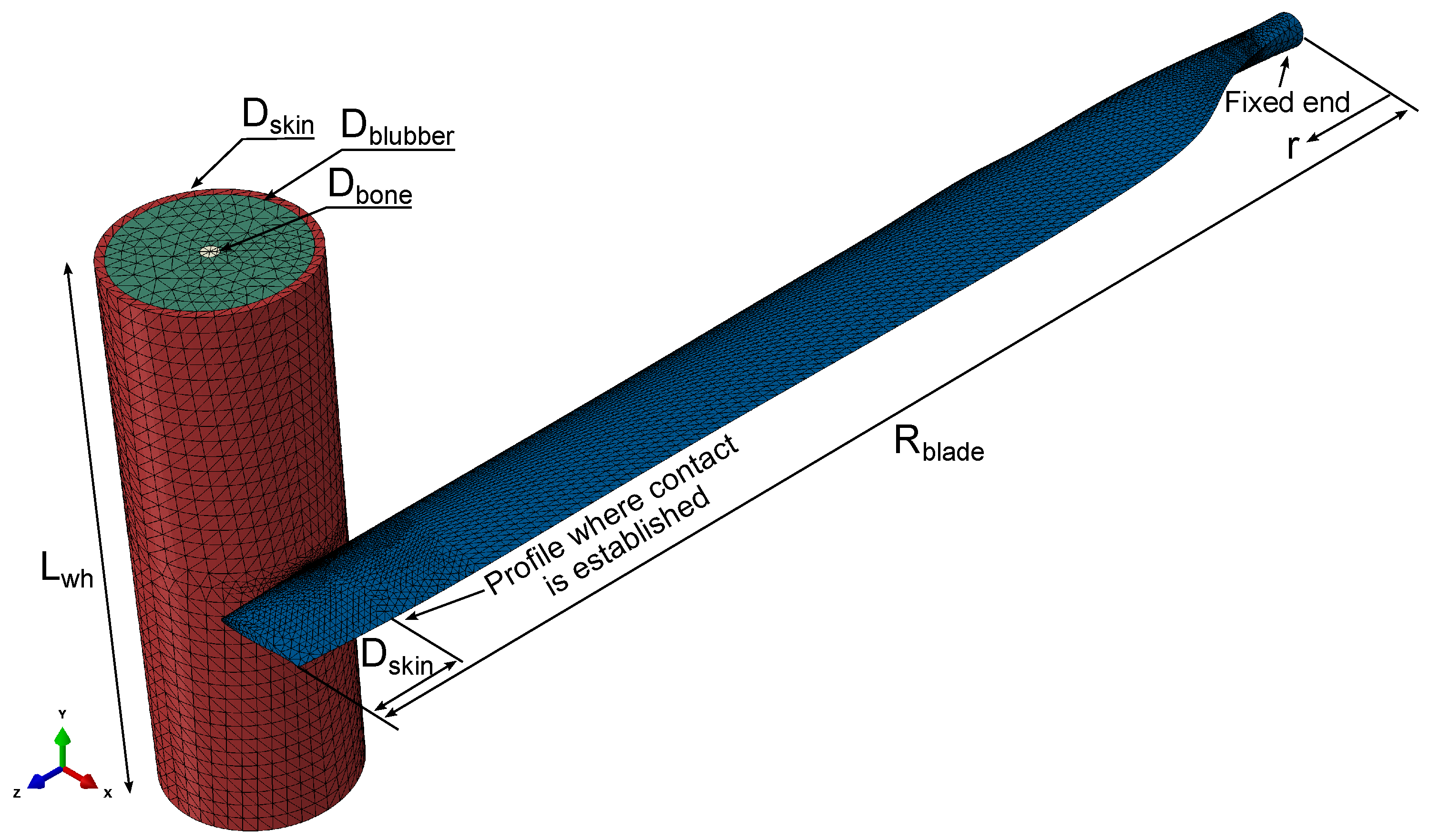
Figure 3.
Visualization of stress distribution at the fixed end of the blade during impact; the contour plot represents von Mises stress [29].
Figure 3.
Visualization of stress distribution at the fixed end of the blade during impact; the contour plot represents von Mises stress [29].
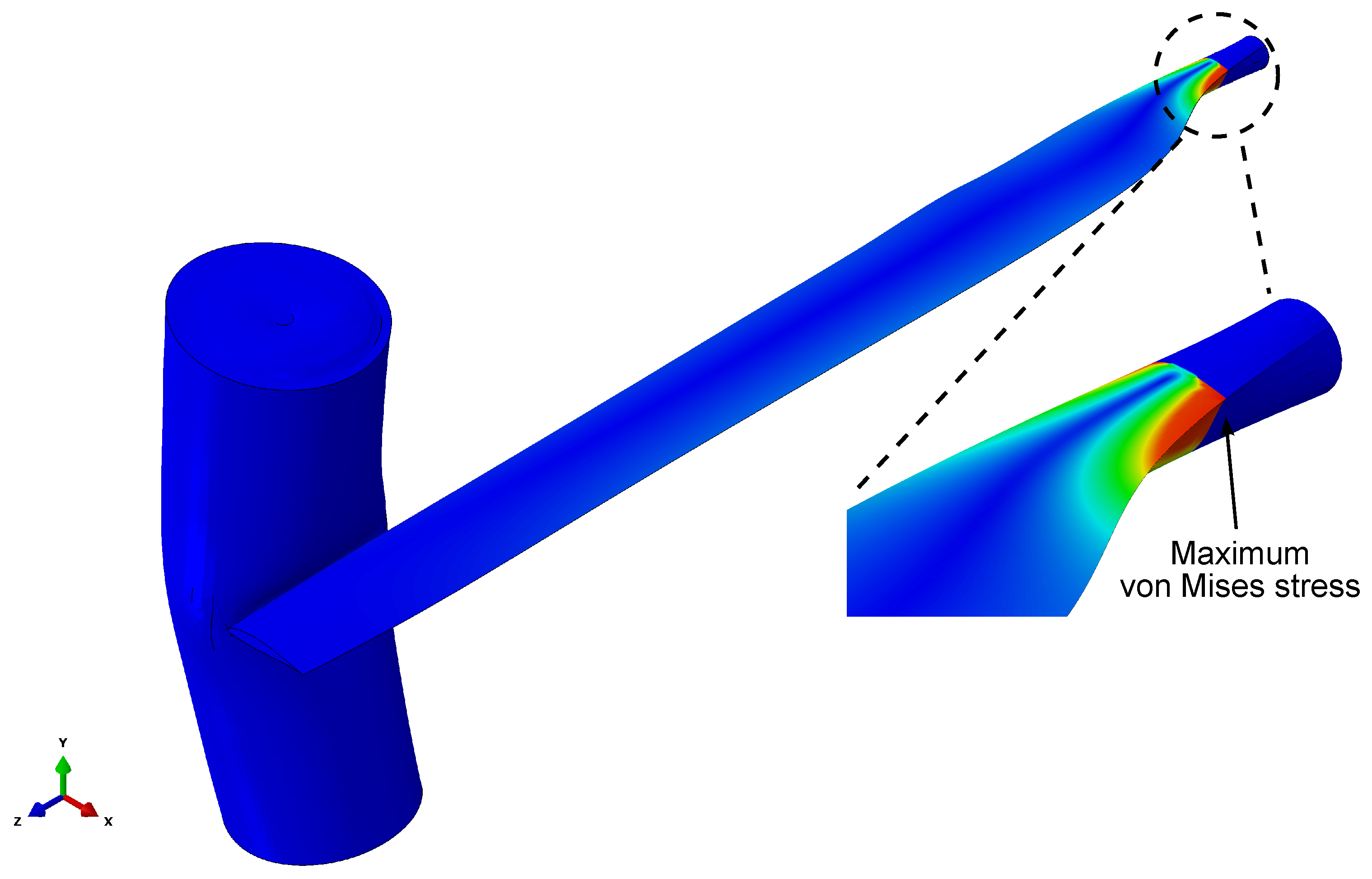
Figure 4.
(a) Normalized kinetic energy with respect normalized time, (b) normalized von Mises stress with respect normalized time at the trailing edge of the foil profile at fixed end, (c) normalized normal stress at z-direction with respect the strain at the trailing edge of the foil profile at fixed end, (d) equivalent plastic strain, for the different velocities of the killer whale; 304 stainless steel material [29].

Figure 5.
Normalized bending moment at y-direction at the fixed end of the blade, with respect to normalized time, for the different velocities of the killer whale.
Figure 5.
Normalized bending moment at y-direction at the fixed end of the blade, with respect to normalized time, for the different velocities of the killer whale.
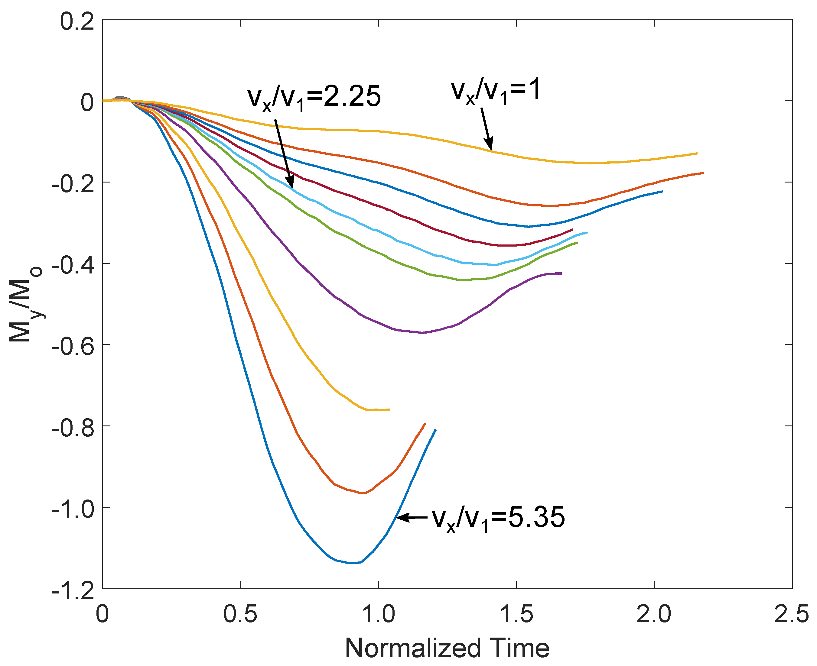
Figure 6.
Normalized bending moment at x-direction at the fixed end of the blade, with respect to normalized time, for the different velocities of the killer whale.
Figure 6.
Normalized bending moment at x-direction at the fixed end of the blade, with respect to normalized time, for the different velocities of the killer whale.
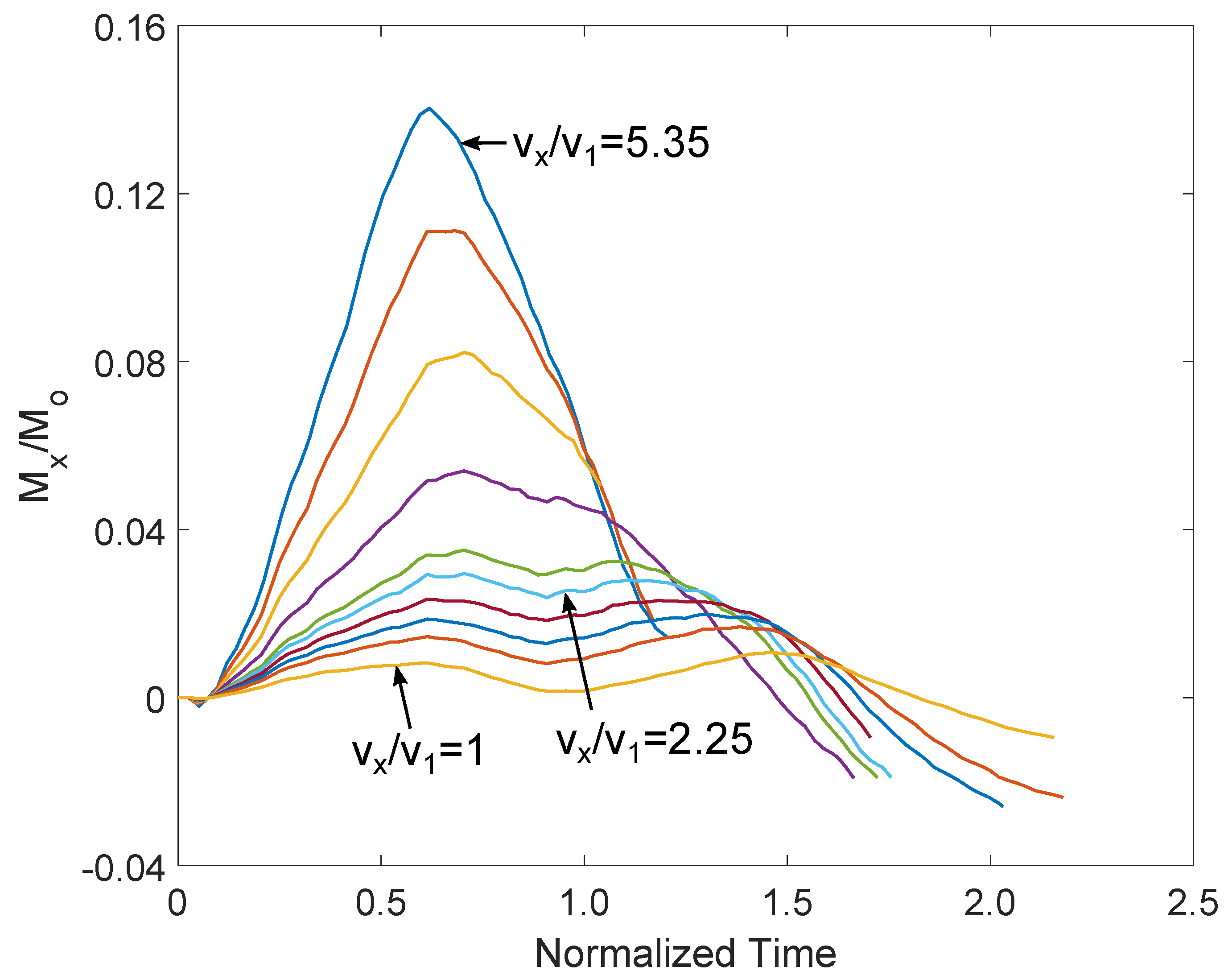
Figure 7.
Normalized translation of centre of rotation of blade’s profile at radial location, for the different velocities of the killer whale at x-direction.
Figure 7.
Normalized translation of centre of rotation of blade’s profile at radial location, for the different velocities of the killer whale at x-direction.
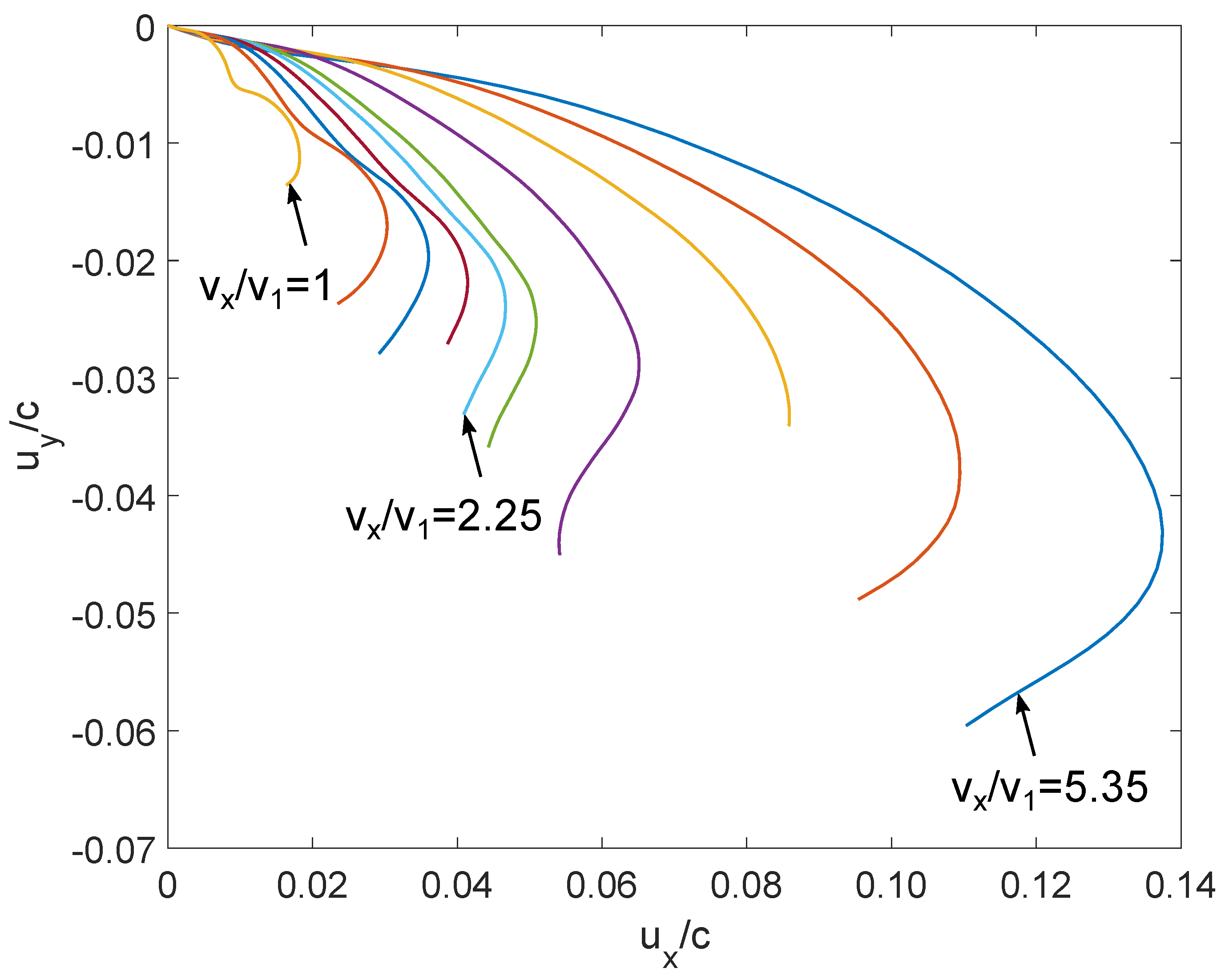
Figure 8.
(a) Normalized kinetic energy with respect normalized time, (b) normalized von Mises stress with respect normalized time at the trailing edge of the foil profile at fixed end, (c) normalized normal stress at z-direction with respect the strain at the trailing edge of the foil profile at fixed end, (d) equivalent plastic strain, for the different velocities of the killer whale; carbon steel material of Grade AISI 1020 [29].
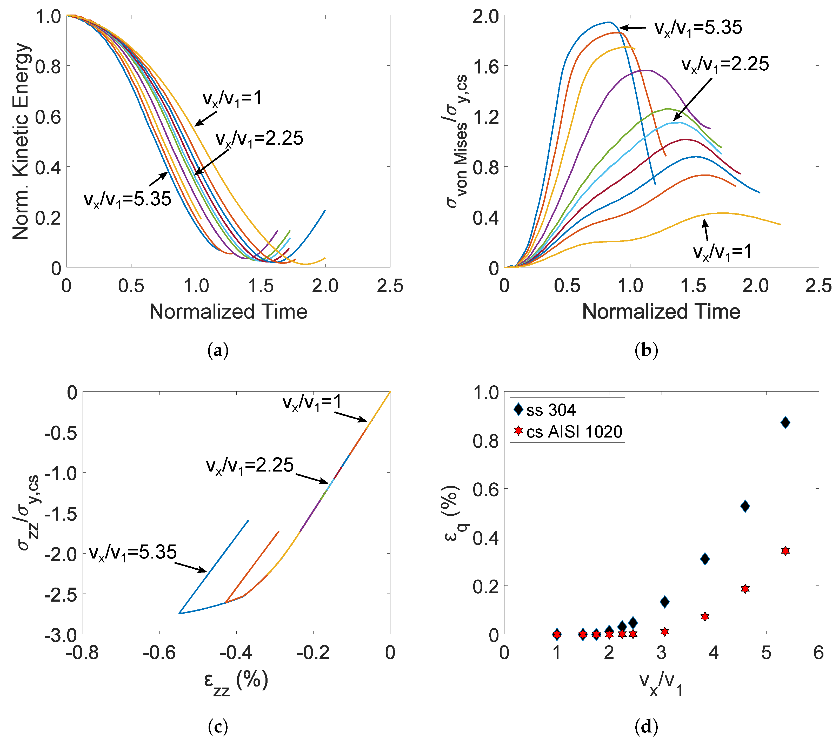
Figure 9.
Normalized normal stress at z-direction with respect to the normal strain at the trailing edge of the foil profile at fixed end, considering ten multiple impacts [29].
Figure 9.
Normalized normal stress at z-direction with respect to the normal strain at the trailing edge of the foil profile at fixed end, considering ten multiple impacts [29].
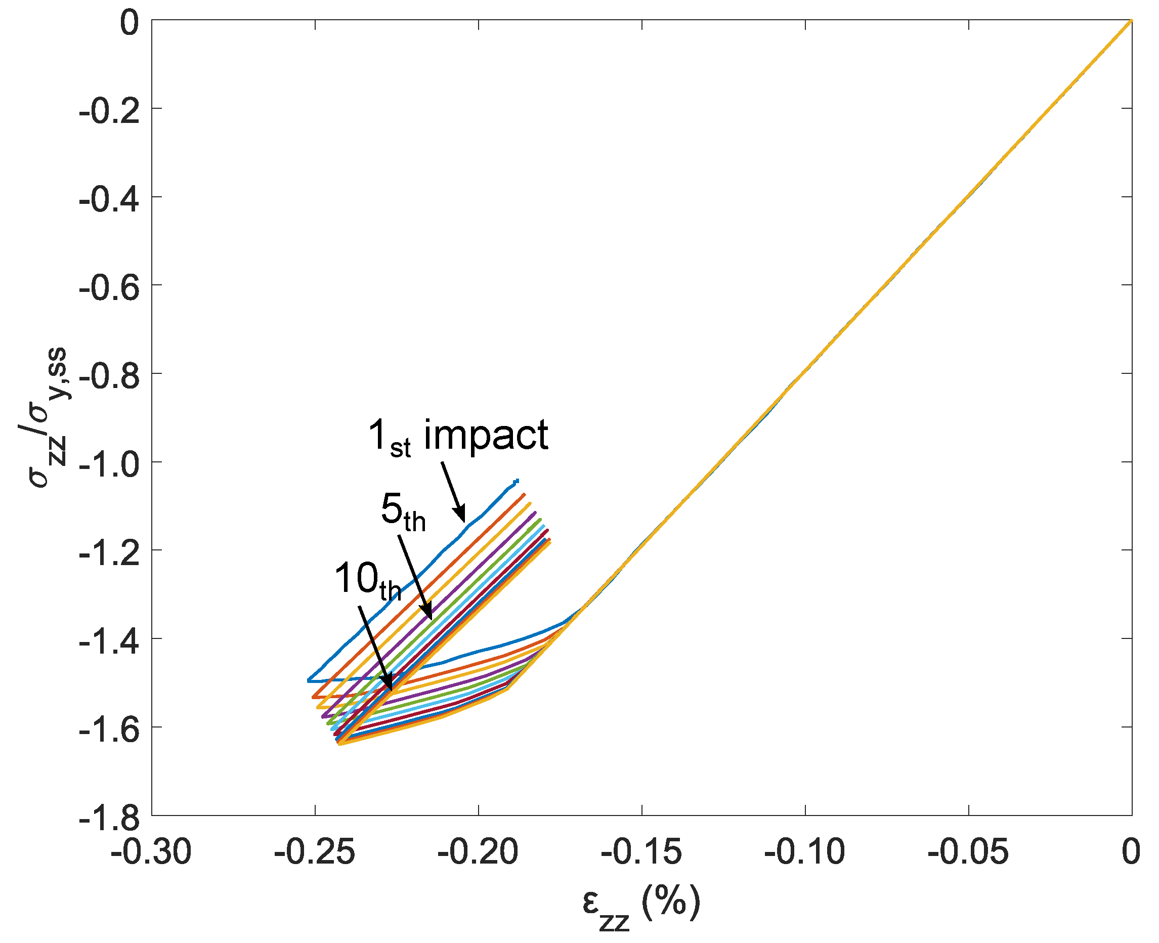
Figure 10.
Equivalent plastic strain () of the stainless steel material of Grade 304 of the tidal turbine blade, with respect to the number of impacts.
Figure 10.
Equivalent plastic strain () of the stainless steel material of Grade 304 of the tidal turbine blade, with respect to the number of impacts.
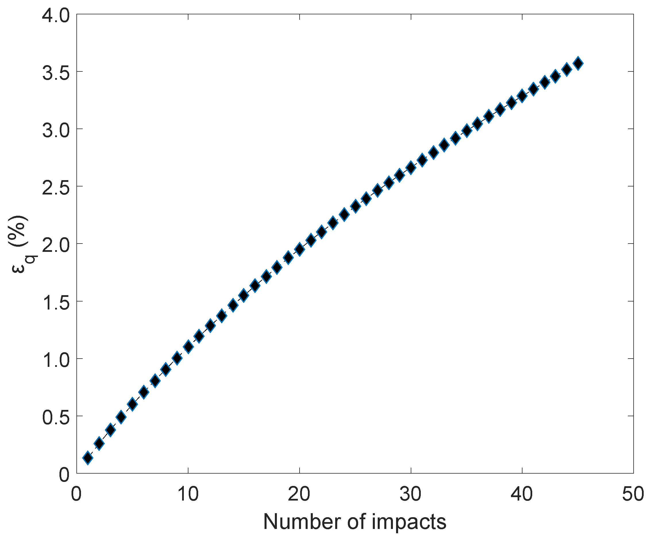
Figure 11.
Normalized kinetic energy of the numerical model, with respect to normalized time, for the different velocities of the killer whale at x-direction; m/s for each case.
Figure 11.
Normalized kinetic energy of the numerical model, with respect to normalized time, for the different velocities of the killer whale at x-direction; m/s for each case.
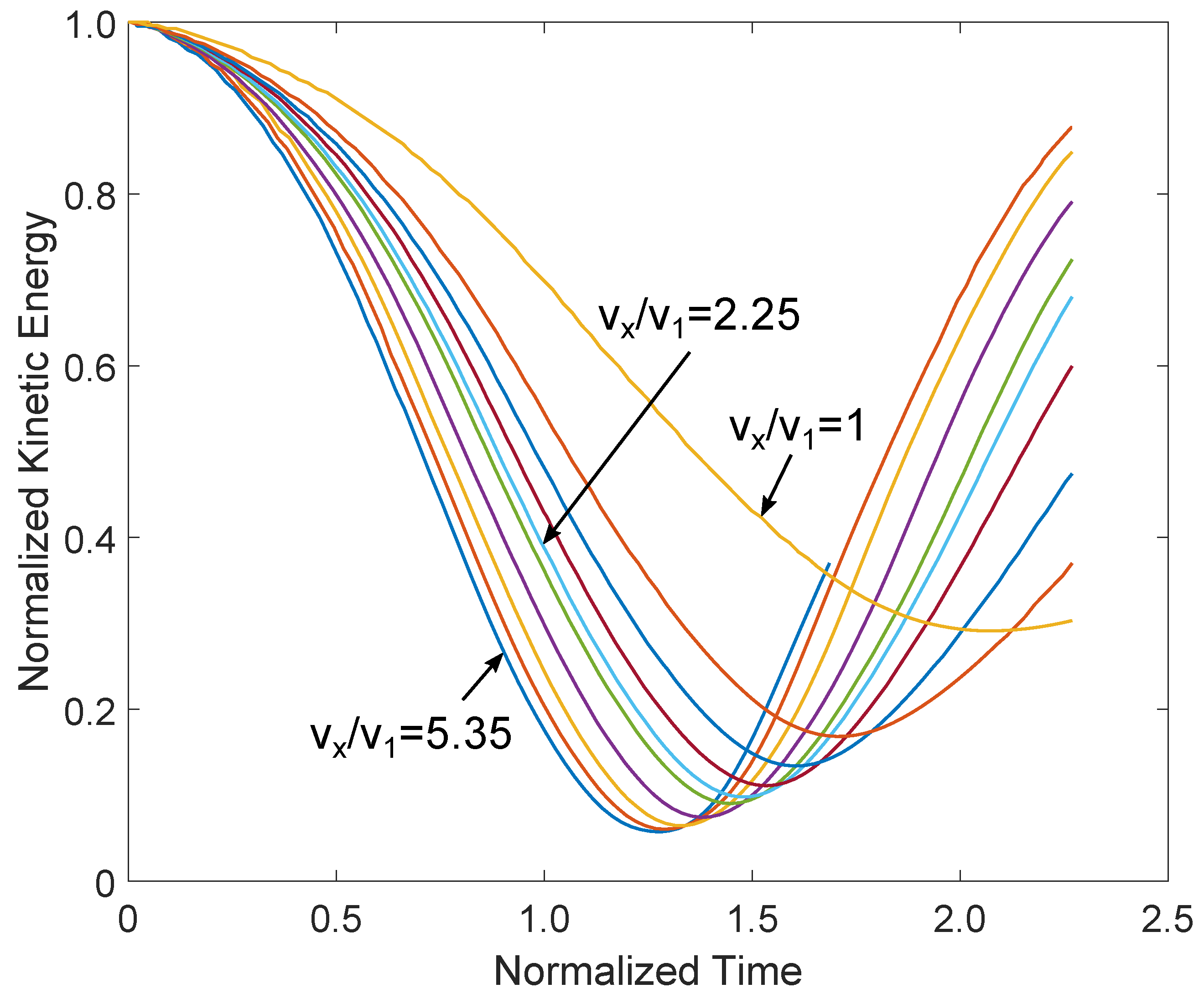
Figure 12.
Normalized translation of centre of rotation of blade’s profile at radial location, for the different velocities of the killer whale at x-direction, considering one-directional and two-directional velocity of the sea animal; m/s for each case.
Figure 12.
Normalized translation of centre of rotation of blade’s profile at radial location, for the different velocities of the killer whale at x-direction, considering one-directional and two-directional velocity of the sea animal; m/s for each case.
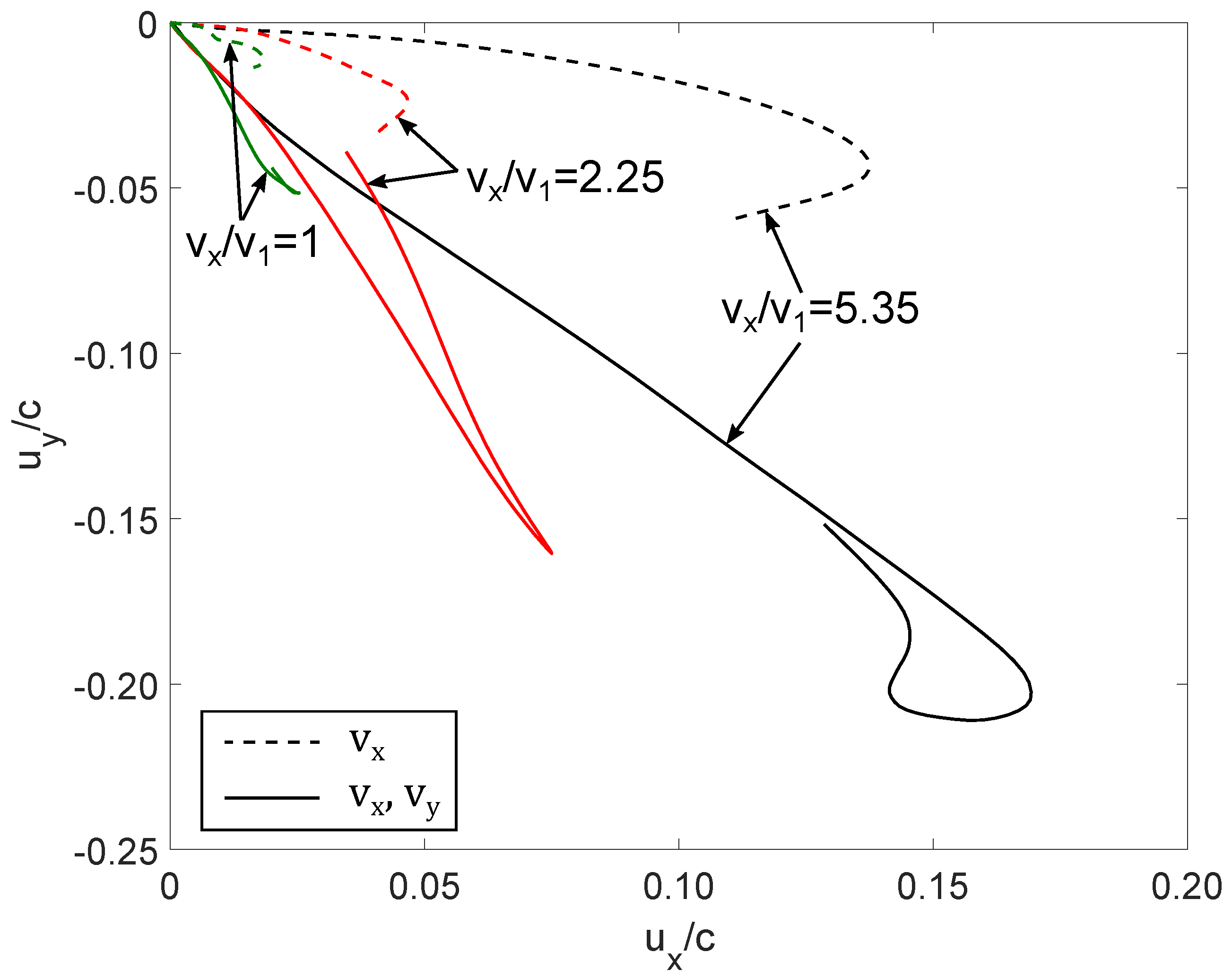
Figure 13.
Equivalent plastic strain of the blade, for the different velocities of the killer whale at x-direction, considering one-directional and two-directional velocity of the sea animal; m/s for each case.
Figure 13.
Equivalent plastic strain of the blade, for the different velocities of the killer whale at x-direction, considering one-directional and two-directional velocity of the sea animal; m/s for each case.
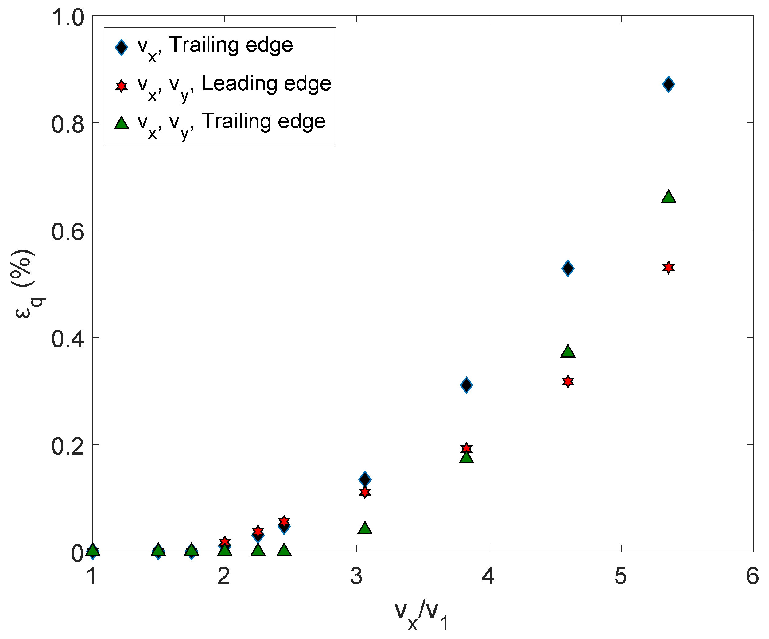
Figure 14.
Graphical representation of the foil profile at radial location.
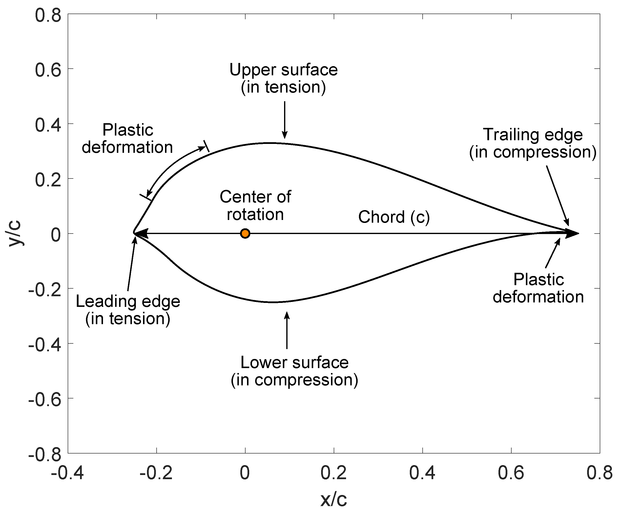
Figure 15.
Visualization of the normalized bending stress () of the foil profile at radial location, in case of normalized velocity of the killer whale at x-direction () equal to ; m/s.
Figure 15.
Visualization of the normalized bending stress () of the foil profile at radial location, in case of normalized velocity of the killer whale at x-direction () equal to ; m/s.

Table 1.
Blade dimensions based on NACA 63-8XX profile series.
| r (mm) | c (mm) | t/c (%) | t (mm) | Twist (°) | ||
|---|---|---|---|---|---|---|
| 0 | 0 | 28.0 | 252.3 | 100.00 | 252.30 | - |
| 0.1 | 900 | 48.3 | 453.0 | 58.00 | 252.30 | 23.00 |
| 0.2 | 1800 | 111.7 | 1005.0 | 25.00 | 251.25 | 19.00 |
| 0.3 | 2700 | 110.9 | 998.4 | 23.45 | 234.15 | 12.35 |
| 0.4 | 3600 | 104.5 | 940.8 | 21.90 | 205.95 | 9.96 |
| 0.5 | 4500 | 98.8 | 889.5 | 20.35 | 181.05 | 8.91 |
| 0.6 | 5400 | 93.2 | 838.8 | 18.80 | 157.65 | 8.00 |
| 0.7 | 6300 | 88.3 | 794.7 | 17.25 | 137.10 | 7.03 |
| 0.8 | 7200 | 85.7 | 771.6 | 15.70 | 121.20 | 6.21 |
| 0.9 | 8100 | 83.0 | 747.3 | 14.15 | 105.75 | 5.74 |
| 0.99 | 8910 | 73.3 | 660.0 | 12.60 | 83.10 | 5.50 |
Table 2.
Material properties of Johnson–Cook parameters for the stainless steel material of Grade 304.
Table 2.
Material properties of Johnson–Cook parameters for the stainless steel material of Grade 304.
| Density (kg/m3) | Young’s Modulus (GPa) | Poisson’s Ratio | (K) | (K) | |
|---|---|---|---|---|---|
| 7900 | 200 | 0.3 | 1673 | 293 | |
| ()(MPa) | B(MPa) | n | c | () | m |
| 310 | 1000 | 0.65 | 0.07 | 1 | 1.00 |
Table 3.
Geometrical properties of the numerical model of the killer whale.
| (m) | (m) | (m) | (m) |
|---|---|---|---|
| 1.200 | 1.091 | 0.109 | 3.557 |
Table 4.
Material properties of Johnson–Cook parameters for the carbon steel material of Grade AISI 1020.
Table 4.
Material properties of Johnson–Cook parameters for the carbon steel material of Grade AISI 1020.
| Density (kg/) | Young’s Modulus (GPa) | Poisson’s Ratio | (K) | (K) | |
|---|---|---|---|---|---|
| 7870 | 200 | 0.3 | 1798 | 293 | |
| A()(MPa) | B(MPa) | n | c | (s−1) | m |
| 333 | 737 | 0.15 | 0.008 | 1 | 1.46 |
Publisher’s Note: MDPI stays neutral with regard to jurisdictional claims in published maps and institutional affiliations. |
© 2021 by the authors. Licensee MDPI, Basel, Switzerland. This article is an open access article distributed under the terms and conditions of the Creative Commons Attribution (CC BY) license (https://creativecommons.org/licenses/by/4.0/).
Share and Cite
MDPI and ACS Style
Gavriilidis, I.; Huang, Y. Finite Element Analysis of Tidal Turbine Blade Subjected to Impact Loads from Sea Animals. Energies 2021, 14, 7208. https://doi.org/10.3390/en14217208
AMA Style
Gavriilidis I, Huang Y. Finite Element Analysis of Tidal Turbine Blade Subjected to Impact Loads from Sea Animals. Energies. 2021; 14(21):7208. https://doi.org/10.3390/en14217208
Chicago/Turabian StyleGavriilidis, Ilias, and Yuner Huang. 2021. "Finite Element Analysis of Tidal Turbine Blade Subjected to Impact Loads from Sea Animals" Energies 14, no. 21: 7208. https://doi.org/10.3390/en14217208
Note that from the first issue of 2016, this journal uses article numbers instead of page numbers. See further details here.