
Energy Saving Approach for an Electric Pump Using a Fuzzy Controller


1
School of Electrical Engineering, Suranaree University of Technology, Nakhon Ratchasima 30000, Thailand
2
Department of Teacher Training in Electrical Engineering, Faculty of Technical Education, King Mongkut’s University of Technology North Bangkok (KMUTNB), Bangkok 10800, Thailand
*
Author to whom correspondence should be addressed.
Energies 2021, 14(11), 3330; https://doi.org/10.3390/en14113330
Submission received: 16 May 2021
/
Revised: 31 May 2021
/
Accepted: 3 June 2021
/
Published: 5 June 2021
(This article belongs to the Special Issue Design and Optimization of Fractional Kilowatt or Medium Power Electrical Machines)
Abstract
:This paper presents an energy-saving approach for electric pumps widely used in agriculture. A capacitor-run single-phase induction motor is used with a centrifugal pump. An appropriate energy-saving frequency and voltage calculation algorithm is proposed in this paper. The fuzzy controller is used to control the water flow rate of the electric pump. Moreover, the adaptive Tabu search algorithm is used to identify induction motor parameters. The experimental results from the energy-saving approach are compared with the valve control and V/f control in terms of input power and power factor. From the experimental results, the electric pump using the proposed energy-saving approach consumes minimum input power compared with other approaches. In addition, the energy-saving approach can provide a good power factor at any flow rate.
1. Introduction
It is well known that the SPIM is widely used in industry because it is inexpensive, durable, and easily maintained. This motor is also widely used in agriculture to drive centrifugal pumps supplying water to plants, and each type of plant requires different quantities of water [1,2]. Therefore, the adjustment of the water flow rate is important, and this rate depends on the motor speed driving the centrifugal pump. However, the flow rate of the water can only be controlled by using the valve adjustment technique and this technique is not suitable for wide areas. The valve control is a simple method to adjust the water flow rate, but this method cannot reduce the input power for energy-saving. Motor speed control is the only option for adjusting the water flow rate. Moreover, motor speed adjustment with voltage control [3,4] or V/f control [5,6,7,8,9] are widely used in many applications. In this paper, the consumed energy of the motor using four techniques to adjust the water flow rate is compared. The system of the SPIM drive, including the centrifugal pump, is shown in Figure 1. A 48-V battery is the energy source of the system. For remote agricultural plots, solar cells may be used as an electric source for electric water pumps. Therefore, the 48-V battery in Figure 1 can be replaced by solar cells. The soft-switching DC-to-DC converter is used to increase the voltage from the energy source for driving the SPIM [10,11,12]. This part consists of a high-frequency inverter circuit, step-up transformer, and rectifier circuit. The input voltage from the DC source is converted to high-frequency AC voltage using the inverter circuit, and this voltage is converted to DC voltage (Va) using the rectifier circuit. In addition, the buck converter and inverter in Figure 1 are used to adjust the appropriate voltage and frequency feeding the SPIM, respectively. The Va is equal to 300 V, and the variable voltage for the source of the inverter varies between 0 and 300 V. The fuzzy controller is used to control the speed of the SPIM to control the water flow rate with the appropriate frequency.
From the literature survey, there are many techniques to drive the SPIM that save energy [13]. In 2001 [14], K. Sundareswaran proposed a method to adjust the voltage of the main coil and directly connect the auxiliary coil to the supply to save energy. Moreover, the voltage control of the auxiliary coil to reduce the motor-starting torque was presented by S.-K. Park et al. [15]. In 2012, V. Thanyaphirak proposed the current ratio control between the main and auxiliary coils using voltage adjustment depending on load quantity [16]. In 2017, R.L. Gorbunov presented an AC buck voltage converter for energy-saving compared with the conventional SCR based on the voltage converter [17]. For the previous works, the voltage adjustment method is applied for energy-saving in the SPIM, while the frequency is fixed to the rated value. However, the frequency adjustment for energy-saving is often applied for the three-phase induction motor [18,19,20,21,22,23]. In circuit theory, it is well known that the impedance of the SPIM depends on the frequency, and the power loss in the SPIM can be reduced by frequency adjustment to the appropriate value. Therefore, the appropriate energy-saving frequency calculation of the SPIM at any speed and load torque is proposed in this paper. Moreover, the SPIM drive using an energy-saving algorithm proposed in this paper has not been reported in previous works. The inverter in Figure 1 is used to adjust the energy-saving frequency of the voltage feeding the SPIM, and the buck converter is used to adjust the voltage with the fuzzy controller to control the water flow rate in terms of SPIM speed. Moreover, it is well known that the fuzzy controller does not need a mathematical model of the system for controller design. Thus, SPIM speed control using the fuzzy controller is proposed in this paper. For the proposed algorithm, the accurate motor parameters are necessary for the frequency calculation to minimize power loss in the SPIM. Therefore, in this paper, the ATS approach is applied for the identification of motor parameters. In addition, the ATS was proven for the convergent property [24,25,26].
This paper is structured as follows. The motor parameter identification using the ATS is presented in Section II. The energy-saving algorithm for the SPIM drive based on the appropriate frequency calculation is explained in Section III. Moreover, Section IV proposes the water flow rate control using the fuzzy controller. In Section V, the experimental results in terms of energy consumed for centrifugal pump driving by the SPIM are presented. Finally, Section VI concludes the paper.
2. SPIM Parameters Identification
The accurate parameters of the motor are necessary for an energy-saving approach to calculate the power losses. In this work, the parameters of the motor can be classified into two groups. In the first group, the parameter is easy to establish by measuring or finding on the data sheet. However, in the second group, it is difficult to know such parameters for the rotor part, mutual inductance, and the moment of inertia. Therefore, the parameters in the second group can be identified using the ATS. In the ATS, back-tracking and adaptive radius mechanisms are applied to escape local deadlock values [24]. Moreover, as proven by mathematical analysis, the ATS ensures that search results can be converged to achieve the best global solution [24,25]. Thus, this paper will present the identification of the six parameters (L1,R2,L2,Lm,La and J) of the SPIM using the ATS. The searching interval of the ATS is set to from the value at rated power by using theoretical equations [27,28,29]. The accurate parameters of the SPIM from the ATS are shown in Table 1. In addition, five parameters in the first group can be measured using laboratory instruments and are found on the data sheet, shown as follows: , , , , and .
The parameter identification process using the ATS can be summarized in Figure 2. The objective function in this work is the between the experiment and simulation as calculated in (1).
In Figure 2, the ATS is applied to search the motor parameters using a SimPowerSystem® toolbox in MATLAB under the ATS concept [30,31] for minimizing the value. The SimPowerSystem® toolbox in MATLAB is used to calculate . This value is used to calculate the , as shown in (1). The searching parameters in SimPowerSystem® are adjusted by the ATS mechanism to minimize the value. There are five important values for the ATS: initial solution = 40, neighbor solution = 60, radius of searching space = 80, decreasing factor of radius = 1.1, and the amount of iteration = 300. These values can be found through testing by simulation to achieve the best solution. The results of the ATS are shown in Table 1. In addition, the convergence of the ATS is illustrated in Figure 3. It can be seen that the value can converge rapidly to the minimum value (0.0276). Moreover, the motor parameters from the ATS are validated with the speed response. The speed response from the simulation using these parameters is compared with the speed response from the experiment, as shown in Figure 4. The response from the simulation is nearly the same as that of the experiment. Therefore, the accurate motor parameters identified by the ATS are used in this work to calculate the power loss of the motor.
3. The Energy-Saving Algorithm
The appropriate frequency calculation algorithm for the SPIM is the energy-saving approach proposed in this paper. Details of this algorithm are described in this section. The appropriated frequency can provide the decreasing input power of the motor. Therefore, the power loss of the motor is reduced. The appropriate frequency at any speed and load torque condition can be calculated from the power losses equation of the capacitor-run SPIM. This equation can be proven from the equivalent circuit, as shown in Figure 5.
Figure 5 shows the equivalent circuit of the SPIM, which consists of the main and auxiliary windings [32]. For the energy-saving concept, the , , and are the considered losses to minimize in the paper. The of the SPIM can be calculated by Equation (2).
where
It is well known that frequency does not significantly affect [33,34,35]. Therefore, frequency adjustment does not affect the reduction of core loss [36]. Moreover, is a very small value compared with [37,38]. Thus, is significant for the appropriate energy-saving frequency calculation. In (2), the depends on the and [36]. It is well known that the steady-state condition is used to analyze energy saving. Therefore, the can be neglected because it is a very small value in the steady-state condition. Thus, depends only on the as shown in (3). It can reduce a complicated equation to a simple equation for loss calculation in this paper.
In previous works on the three-phase induction motor [18,19,20,21,22,23], the appropriate frequency can be calculated from the derivative of the total power loss with respect to a frequency equal to 0, and this is a concept for energy saving. This concept is applied for energy-saving purposes in the SPIM in this paper. However, this concept is complicated and consuming. Therefore, a new approach to calculate the appropriate energy-saving frequency is proposed. The derivative of the main coil current with respect to a frequency equal to 0 () is the new approach to finding the appropriate energy-saving frequency proposed in this paper. Moreover, the computational results in Figure 6 show that there are appropriate frequency values at any speeds of the motor to minimize total power losses. The algorithm to calculate the appropriate frequency to minimize loss is presented in this paper. In Figure 6, the appropriate frequency can be calculated from the derivative of the main coil current with respect to a frequency equal to 0. This principle is called “the energy-saving algorithm”. In this paper, the proposed algorithm will be applied in the SPIM driving the centrifugal pumps.
In machine theory, the main coil current of the SPIM depends on and , as depicted in (4). and can be calculated in (5) and (6), respectively.
The and terms are small values compared with . Therefore, and can be rearranged in terms of and to decrease the complexity, as shown in (7) and (8), respectively.
In this paper, the derivative of the main coil current with respect to a frequency equal to 0 in (9) is applied to calculate the appropriate energy-saving frequency. The variables of A, B, C, and D can be expressed in (10) to (13), respectively.
where
4. FUZZY Controller Design
The appropriate energy-saving frequency calculation proposed in the previous section can provide minimum power loss for the SPIM drive-fed centrifugal pump. The appropriate frequency from the energy-saving algorithm part shown in Figure 1 is sent to the inverter to adjust the frequency feeding the motor. This is because the frequency adjustment alone cannot control the motor speed equal to the speed reference. Therefore, the water flow rate cannot be controlled to a constant value. In this section, the motor speed control to keep the flow rate of water to a constant value is described. It is well known that the fuzzy controller is widely used in many engineering applications because of its efficiency, intelligence, and human-like decision making [43,44,45]. In addition, it does not require the mathematical model of the system for controller design. Therefore, in this paper, the fuzzy controller is used to control the motor speed. In Figure 1, the buck converter adjusts the peak voltage feeding the motor to control the motor speed, for tracking the reference speed. The speed error (es) between the and the calculated by (14) is the fuzzy input, as depicted in Table 2. The of switch is the fuzzy output.
Details of the linguistic variables and linguistic values of the fuzzy controller and the definition in this work are shown in Table 2. A triangular shape is applied for the membership functions (MF) of the input error with five linguistic values (very_neg, neg, zero, pos, very_pos), as depicted in Figure 7. The duty cycle is used as the output MF of the fuzzy controller. The zero-order Takagi-Sugeno model or the bar constant shape is applied for the output MF, as shown in Figure 8, with five linguistic values (very_dec, dec, cons, inc, very_inc). Moreover, the input and output MF parameters of the fuzzy controller used in this paper are presented in Table 3. The trial-and-error method will be applied to define the parameters of the fuzzy controller for the minimum error between the reference speed and the actual speed of the SPIM.
The Takagi–Sugeno fuzzy inference is selected herein because it is appropriate for the real-time system [46]. In addition, the weighted average method [45] is used to calculate the fuzzy output in the defuzzification process, as shown by (15). For this process, μ(km) is the MF value, and the output value is represented by .
Speed tracking using the fuzzy controller is shown in Figure 9. The actual speed (solid line) can track the reference speed (dash line). Thus, the proposed fuzzy controller can be used to control the speed of the SPIM.
5. The Experimental Result
The experimental result of the energy-saving approach proposed in this paper is presented in this section. The testing rig of the considered system in Figure 1 is depicted in Figure 10. The 48-V battery is the main source of the system, and the soft-switching DC/DC converter is used to increase the DC voltage from the battery before supplying the voltage to the buck converter. The buck converter is the main part that adjusts the peak voltage feeding the SPIM to control the speed. In addition, the inverter is applied to adjust the appropriate frequency from the energy-saving algorithm to minimize the power loss of the SPIM at any speed.
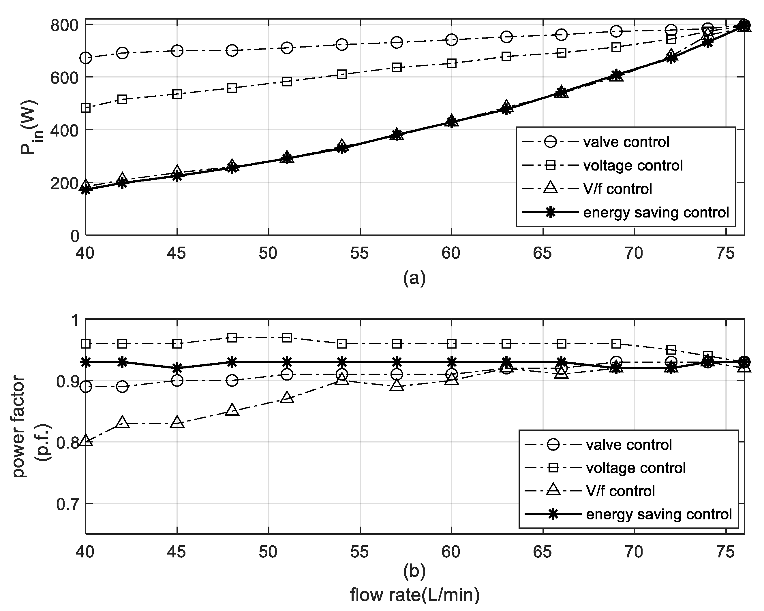
The Arduino MEGA 1280 microcontroller board is the main processor used to calculate the appropriate energy-saving frequency and control the motor speed using the fuzzy controller. This microcontroller is not expensive, and it is suitable for commercial use. The specifications of the ACH-375S series, which includes the combination of the SPIM and the centrifugal pump, are 0.5-hp, 220-V, 50-Hz, and 2762-rpm. In this paper, there are four methods for testing the consumed energy in terms of the input power and the power factor, such as valve control, voltage control [3,4], V/f control [5,6,7,8,9], and the energy-saving approach. The water flow rate value for testing is varied from 40 to 76 L/min. The water flow rate control uses the fuzzy controller to control the motor speed. The experimental results are shown in Figure 11.
From the results in Figure 11a, the input power from the energy-saving approach can provide minimum input power compared with other methods at any flow rate. In the case of power factor correction, the voltage control is the method to achieve the best power factor, as shown in Figure 11b. Nevertheless, this method consumes the input power more than the V/f and the energy-saving control. For the V/f control, the consumed input power is nearly the same as the energy-saving approach, and the power factor is low in value compared with other methods. Unfortunately, the proposed method cannot provide the best power factor because the power factor will slightly decrease when the input power is reduced but the apparent power is constant. However, the proposed method can provide a higher power factor than the V/f control, as shown in Figure 11b. Thus, the experimental results can confirm that the energy-saving approach proposed in the paper can provide minimum loss, and it is suitable for driving the electric pump to save energy. In addition, the maximum percentage of energy saving will appear at a flow rate equal to 40 L/min, as depicted in Figure 11. The percentages of the energy saved form the proposed method compared with the valve control, voltage control, and V/f control are equal to 74.31, 64.25, and 5.94, respectively. However, the percentage of energy saving is decreased when the flow rate is increased. Therefore, this is a significant consideration for improving the energy saving approach in the future. From the experimental results in this section, the results can confirm that the proposed algorithm can provide minimum power losses from the motor in terms of energy saving. Moreover, this algorithm can reduce electrical consumption and increase motor life.
6. Conclusions
The energy-saving approach is proposed to minimize power loss from the SPIM drive-fed centrifugal pump. The calculation of the appropriate energy-saving frequency is also presented. Moreover, the parameters in the rotor part, mutual inductance and the moment of inertia are identified by using the ATS because these parameters are difficult to know or measure. The fuzzy controller is applied to control the motor speed to maintain the constant flow rate of the water. The details of the fuzzy control are summarized in the paper. In addition, the hardware setup in the laboratory is also presented in the paper. There are four methods for testing the consumed energy in terms of the input power and the power factor, such as valve control, voltage control, V/f control, and the energy-saving approach. The experimental results show that the proposed energy-saving algorithm can provide minimum power loss for driving the SPIM at any flow rate. The motor using the energy-saving approach and V/f control nearly consumes the input power, but the energy-saving approach can provide a good result in terms of the power factor. Moreover, the SPIM drive-fed centrifugal pump using the energy-saving approach can increase motor life and reduce electrical consumption.
Author Contributions
Conceptualization, investigation and data analysis, K.A. (Kongpol Areerak) and K.A. (Kongpan Areerak); software and validation, data gathering, T.S.; writing—original draft preparation, J.P.; writing—review and editing, J.P., and K.A. (Kongpol Areerak); supervision and project administration, K.A. (Kongpol Areerak). All authors have read and agreed to the published version of the manuscript.
Funding
This research received no external funding.
Institutional Review Board Statement
Not applicable.
Informed Consent Statement
Not applicable.
Data Availability Statement
Not applicable.
Acknowledgments
This work was supported by Suranaree University of Technology (SUT) and by Thailand Science Research and Innovation (TSRI).
Conflicts of Interest
The authors declare no conflict of interest.
Nomenclatures
| AC | alternating current |
| ATS | adaptive Tabu search |
| DC | direct current |
| V/f | voltage per frequency |
| SCR | silicon control rectifier |
| SPIM | single-phase induction motor |
| C | motor capacitance (F) |
| Cb | buck converter capacitance (F) |
| I1 | main coil current (A) |
| I2 | auxiliary coil current (A) |
| J | moment of inertia (kg·m2) |
| Lb | buck converter inductance (H) |
| Lm | mutual inductance (H) |
| Lmutual | mutual inductance (H) |
| L1 | main coil inductance (H) |
| L2 | rotor inductance (H) |
| La | auxiliary coil inductance (H) |
| NT | number of data |
| P | number of poles |
| Pcore | core copper loss (W) |
| Plosses | total power losses (W) |
| Prcl | rotor copper loss (W) |
| Pscl | stator copper loss (W) |
| Ra | auxiliary coil resistance (Ω) |
| R1 | main coil resistance (Ω) |
| R2 | rotor resistance (Ω) |
| Speedactual | actual speed (rpm) |
| Speedexperiment | experimental speed (rpm) |
| Speedreference | reference speed (rpm) |
| Speedsimulation | simulated speed (rpm) |
| VAC | input voltage of SPIM (V) |
| Va | input voltage for buck converter (V) |
| Vb | output voltage of buck converter (V) |
| Vbatt | battery voltage (V) |
| V1 | input voltage of the main and auxiliary coils (V) |
| Xm | magnetizing reactance (Ω) |
| X2 | rotor reactance (Ω) |
| Zf | forward impedance (Ω) |
| Zb | backward impedance (Ω) |
| a | turn ratio of coil |
| d | duty cycle (0–100%) |
| errorav | average errors of the motor speed (rpm) |
| es | speed error (rpm) |
| f | frequency (Hz) |
| kc | coefficient of core loss |
| S | slip of induction machine |
| x1,x2,…,x14 | input membership function of fuzzy controller |
| y1,y2,…,y5 | output membership function of fuzzy controller |
References
- Salvador, R.; Bautista-Capetillo, C.; Playán, E. Irrigation performance in private urban landscapes: A study case in Zaragoza (Spain). Landsc. Urban Plan. 2011, 100, 302–311. [Google Scholar] [CrossRef] [Green Version]
- Farooq, M.; Hussain, M.; Ul-Allah, S.; Siddique, K.H.M. Physiological and agronomic approaches for improving water-use efficiency in crop plants. Agric. Water Manag. 2019, 219, 95–108. [Google Scholar] [CrossRef]
- Law, J.D.; Lipo, T.A. A single phase induction motor voltage controller with improved performance. In Proceedings of the 1984 IEEE Power Electronics Specialists Conference, Gaithersburg, MD, USA, 18–21 June 1984. [Google Scholar]
- Jannati, M.; Anbaran, S.A.; Asgari, S.H.; Goh, W.Y.; Monadi, A.; Aziz, M.J.A.; Idris, N.R.N. A review on Variable Speed Control techniques for efficient control of Single-Phase Induction Motors: Evolution, classification, comparison. Renew. Sustain. Energy Rev. 2017, 75, 1306–1319. [Google Scholar] [CrossRef]
- Piyarat, W.; Hothongkham, P.; Charumit, C.; Kinnares, V. Simple speed control of an asymmetrical type two-phase induction motor drive. In Proceedings of the ECTI-CON2010: The 2010 ECTI International Confernce on Electrical Engineering/Electronics, Computer, Telecommunications and Information Technology, Chiang Mai, Thailand, 19–21 May 2010. [Google Scholar]
- Collins, E.R. Torque and slip behavior of single-phase induction motors driven from variable-frequency supplies. IEEE Trans. Ind. Appl. 1992, 28, 710–715. [Google Scholar] [CrossRef]
- Gastli, A.; Matsui, N. Stator flux controlled V/f PWM inverter with identification of IM parameters (induction motors). IEEE Trans. Ind. Electron. 1992, 39, 334–340. [Google Scholar] [CrossRef]
- Kafle, B.; Basnet, P.; Ghimire, A.; Lamichhane, A. Speed Control of a Single Phase Induction Motor using the V/f Method. In Proceedings of the 2019 Innovations in Power and Advanced Computing Technologies (i-PACT), Vellore, India, 22–23 March 2019. [Google Scholar]
- Qudsi, O.A.; Rosalina, I.I.; Yanaratri, D.S. V/f SPWM Inverter for Single-phase Induction Motor Contrller Using Adaptive Neuro-Fuzzy Inference System. In Proceedings of the 2018 3rd International Conference on Information Technology, Information System and Electrical Engineering (ICITISEE), Yogyakarta, Indonesia, 13–14 November 2018. [Google Scholar]
- Batarseh, I.; Harb, A. Soft-Switching dc-dc Converters. In Power Electronics: Circuit Analysis and Design; Batarseh, I., Harb, A., Eds.; Springer International Publishing: Cham, Germany, 2018; pp. 347–460. [Google Scholar]
- Yung-Fu, H.; Chih-Wen, L.; Yoshihiro, K. Soft-switching PWM full-bridge DC-DC converter with energy recovery transformer and auxiliary passive lossless snubbers. In Proceedings of the INTELEC 07—29th International Telecommunications Energy Conference, Rome, Italy, 30 September–4 October 2007. [Google Scholar]
- Sabate, J.A.; Vlatkovic, V.; Ridley, R.B.; Lee, F.C.; Cho, B.H. Design considerations for high-voltage high-power full-bridge zero-voltage-switched PWM converter. In Proceedings of the Fifth Annual Proceedings on Applied Power Electronics Conference and Exposition, Los Angeles, CA, USA, 1–16 March 1990. [Google Scholar]
- Ma, W.; Bai, L. Energy-Saving Principles and Technologies for Induction Motors; Wiley: Hoboken, NJ, USA, 2018. [Google Scholar]
- Sundareswaran, K. An improved energy-saving scheme for capacitor-run induction motor. IEEE Trans. Ind. Electron. 2001, 48, 238–240. [Google Scholar] [CrossRef]
- Park, S.-K.; Lim, H.-W.; Cho, G.-b.; Baek, H.L.; Lee, S.-K.; Chang, Y.-H.; Seo, J.-Y. A study on the reduction of in-rush current for energy saving of single phase induction motor. in ICEMS’2001. In Proceedings of the Fifth International Conference on Electrical Machines and Systems (IEEE Cat. No.01EX501), Shenyang, China, 18–20 August 2001. [Google Scholar]
- Thanyaphirak, V.; Kinnares, V.; Kunakorn, A. PWM AC chopper control schemes for energy saving of single-phase induction motors. In Proceedings of the 2012 10th International Power & Energy Conference (IPEC), Ho Chi Minh City, Vietnam, 12–14 December 2012. [Google Scholar]
- Gorbunov, R.L. Power conversion quality of AC buck voltage converter in comparison with SCR voltage converter. In Proceedings of the 2017 18th International Conference of Young Specialists on Micro/Nanotechnologies and Electron Devices (EDM), Erlagol, Russia, 29 June–3 July 2017. [Google Scholar]
- Famouri, P.; Cathey, J.J. Loss minimization control of an induction motor drive. IEEE Trans. Ind. Appl. 1991, 27, 32–37. [Google Scholar] [CrossRef]
- Kirschen, D.S.; Novotny, D.W.; Suwanwisoot, W. Minimizing Induction Motor Losses by Excitation Control in Variable Frequency Drives. IEEE Trans. Ind. Appl. 1984, IA-20, 1244–1250. [Google Scholar] [CrossRef]
- Kusko, A.; Galler, D. Control Means for Minimization of Losses in AC and DC Motor Drives. IEEE Trans. Ind. Appl. 1983, IA-19, 561–570. [Google Scholar] [CrossRef]
- Molina, J.J.M.; Scarpetta, J.M.R. Optimal U/f Control for Induction Motors. IFAC Proc. Vol. 2002, 35, 329–333. [Google Scholar] [CrossRef]
- Sridharan, S.; Krein, P.T. Induction motor drive design for traction application based on drive-cycle energy minimization. In Proceedings of the 2014 IEEE Applied Power Electronics Conference and Exposition—APEC 2014, Fort Worth, TX, USA, 16–20 March 2014. [Google Scholar]
- Yin, S.; Meng, D.; Diao, L.; Li, Y.; Dong, K. Improved hybrid loss control with optimized flux for traction induction motor under light load. IEEJ Trans. Electr. Electron. Eng. 2019, 14, 485–492. [Google Scholar] [CrossRef]
- Puangdownreong, D.; Areerak, K.-N.; Srikaew, A.; Sujitjorn, S.; Totarong, P. System identification via Adaptive Tabu Search. In Proceedings of the 2002 IEEE International Conference on Industrial Technology, Bankok, Thailand, 11–14 December 2002. [Google Scholar]
- Sujitjorn, S.; Kulworawanichpong, T.; Puangdownreong, D.; Areerak, K.-N. Adaptive Tabu Search and Applications in Engineering Design. In Proceedings of the Integrated Intelligent Systems for Engineering Design, Amsterdam, The Netherlands, 30 May 2006; pp. 233–257. [Google Scholar]
- Ketthanom, C.; Artameeyanant, P.; Pratumshat, V. Application of Adaptive Tabu Search to PIDA Controller Design. In Proceedings of the 2019 16th International Conference on Electrical Engineering/Electronics, Computer, Telecommunications and Information Technology (ECTI-CON), Pattaya, Thailand, 10–13 July 2019. [Google Scholar]
- Guinee, R.A.; Lyden, C. Motor parameter identification using response surface simulation and analysis. In Proceedings of the 2001 American Control Conference. (Cat. No.01CH37148), Arlington, VA, USA, 25–27 June 2001. [Google Scholar]
- Warachart, S.-K.; Lumyong, P. Characteristics evaluation of 3 phase induction motors based on an acceleration method with increasing moment of inertia technique. In Proceedings of the 4th IEEE International Symposium on Diagnostics for Electric Machines, Power Electronics and Drives, 2003. SDEMPED 2003, Atlanta, GA, USA, 24–26 August 2003. [Google Scholar]
- Andoh, F. Moment of Inertia Identification Using the Time Average of the Product of Torque Reference Input and Motor Position. IEEE Trans. Power Electron. 2007, 22, 2534–2542. [Google Scholar] [CrossRef]
- Pakdeeto, J.; Chanpittayagit, R.; Areerak, K.-N.; Areerak, K.-L. The Optimal Controller Design of Buck-Boost Converter by using Adaptive Tabu Search Algorithm Based on State-Space Averaging Model. J. Electr. Eng. Technol. 2017, 12, 1146–1155. [Google Scholar] [CrossRef] [Green Version]
- Udomsuk, S.; Areerak, K.-L.; Areerak, K.-N.; Srikaew, A. Parameters identification of separately excited DC motor using adaptive tabu search technique. In Proceedings of the 2010 International Conference on Advances in Energy Engineering, Beijing, China, 19–20 June 2010. [Google Scholar]
- Boldea, I.; Nasar, S.A. The Induction Machines Design Handbook; CRC Press/Taylor & Francis: Boca Raton, FL, USA, 2010. [Google Scholar]
- Mannan, A.; Murata, T.; Tamura, J.; Tsuchiya, T. Efficiency optimized speed control of field oriented induction motor including core loss. In Proceedings of the Power Conversion Conference-Osaka 2002 (Cat. No.02TH8579), Osaka, Japan, 2–5 April 2002. [Google Scholar]
- Piazza, M.C.D.; Luna, M.; Pucci, M. Electrical Loss Minimization Technique for Wind Generators Based on a Comprehensive Dynamic Modeling of Induction Machines. IEEE Trans. Ind. Appl. 2017, 53, 3696–3706. [Google Scholar] [CrossRef]
- Bazzi, A.M.; Krein, P.T. Review of Methods for Real-Time Loss Minimization in Induction Machines. IEEE Trans. Ind. Appl. 2010, 46, 2319–2328. [Google Scholar] [CrossRef]
- Li, Y.; Adeleke, O.P.; Xu, X. Methods and applications of energy saving control of in-wheel motor drive system in electric vehicles: A comprehensive review. J. Renew. Sustain. Energy 2019, 11, 062701. [Google Scholar] [CrossRef]
- Aarniovuori, L.; Niemelä, M.; Pyrhönen, J.; Cao, W.; Agamloh, E.B. Loss Components and Performance of Modern Induction Motors. In Proceedings of the 2018 XIII International Conference on Electrical Machines (ICEM), Alexandroupoli, Greece, 3–6 September 2018. [Google Scholar]
- Emadi, A.; Andreas, J.C. Energy-Efficient Electric Motors; Marcel Dekker: New York, NY, USA, 2005. [Google Scholar]
- Russell, S.J.; Norvig, P. Artificial Intelligence: A Modern Approach; Pearson Education: Harlow, UK, 2016. [Google Scholar]
- Pfingsten, G.V.; Steentjes, S.; Hameyer, K. Operating Point Resolved Loss Calculation Approach in Saturated Induction Machines. IEEE Trans. Ind. Electron. 2017, 64, 2538–2546. [Google Scholar] [CrossRef]
- Pfingsten, G.V.; Steentjes, S.; Hameyer, K. Transient approach to model operating point dependent losses in saturated induction machines. In Proceedings of the 2016 XXII International Conference on Electrical Machines (ICEM), Lausanne, Switzerland, 4–7 September 2016. [Google Scholar]
- Palanisamy, V.; Vijayanathan, S. A Novel Agent Based Depth First Search Algorithm. In Proceedings of the 2020 IEEE 5th International Conference on Computing Communication and Automation (ICCCA), Greater Noida, India, 30–31 October 2020. [Google Scholar]
- Takagi, T.; Sugeno, M. Fuzzy identification of systems and its applications to modeling and control. IEEE Trans. Syst. Man Cybern. 1985, SMC-15, 116–132. [Google Scholar] [CrossRef]
- Narongrit, T.; Areerak, K.-L.; Areerak, K.-N. Adaptive Fuzzy Control for Shunt Active Power Filters. Electr. Power Compon. Syst. 2016, 44, 646–657. [Google Scholar] [CrossRef]
- Narongrit, T.; Areerak, K.-L.; Areerak, K.-N. A New Design Approach of Fuzzy Controller for Shunt Active Power Filter. Electr. Power Compon. Syst. 2015, 43, 685–694. [Google Scholar] [CrossRef]
- Shukla, S.; Mishra, S.; Singh, B. TS fuzzy based intelligent control of a three phase shunt filter under balanced and unbalanced conditions. In Proceedings of the 2010 Joint International Conference on Power Electronics, Drives and Energy Systems & 2010 Power India, New Delhi, India, 20–23 December 2010. [Google Scholar]
Figure 1.
The SPIM drive system for the centrifugal pump.
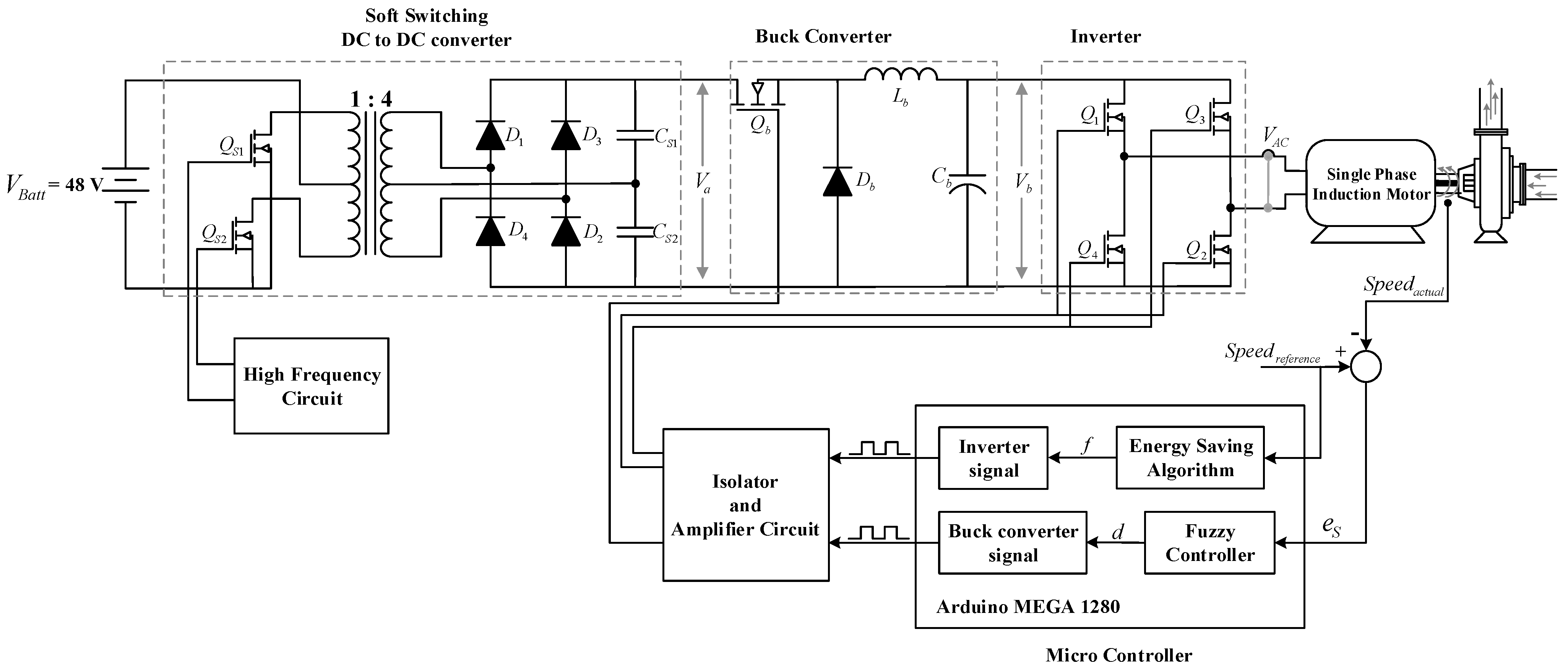
Figure 2.
Diagram of motor parameter identification using the ATS.
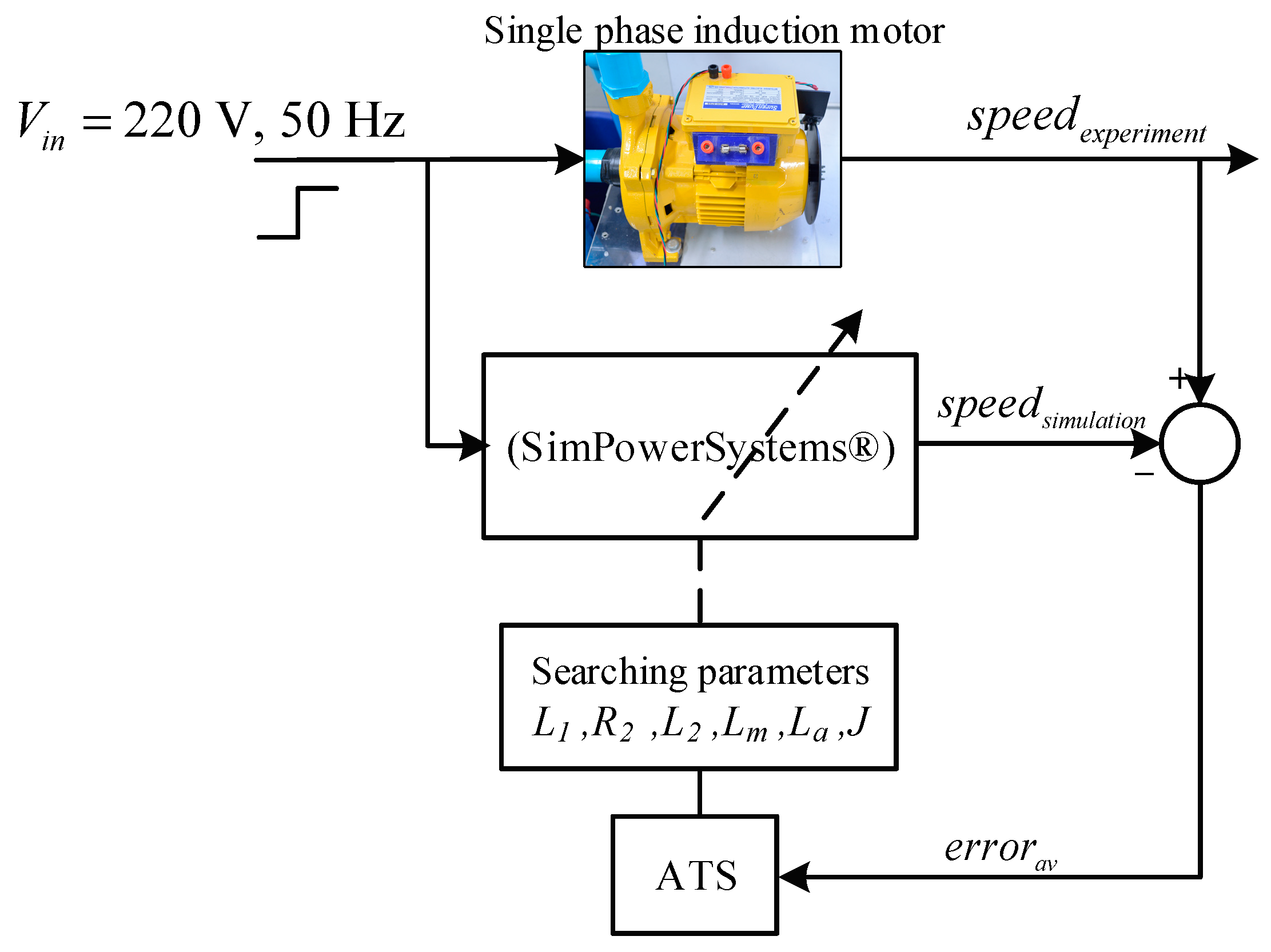
Figure 3.
The convergence of .
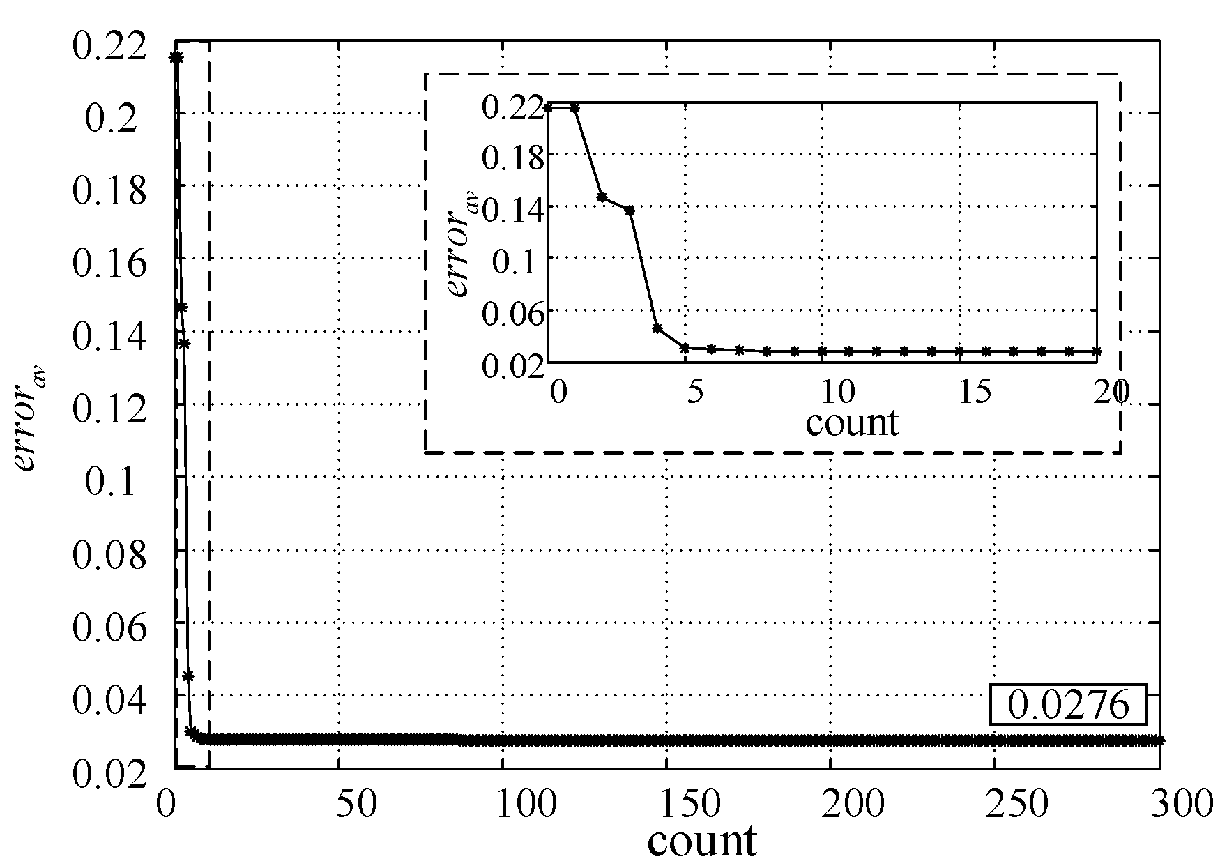
Figure 4.
The comparison of speed response.
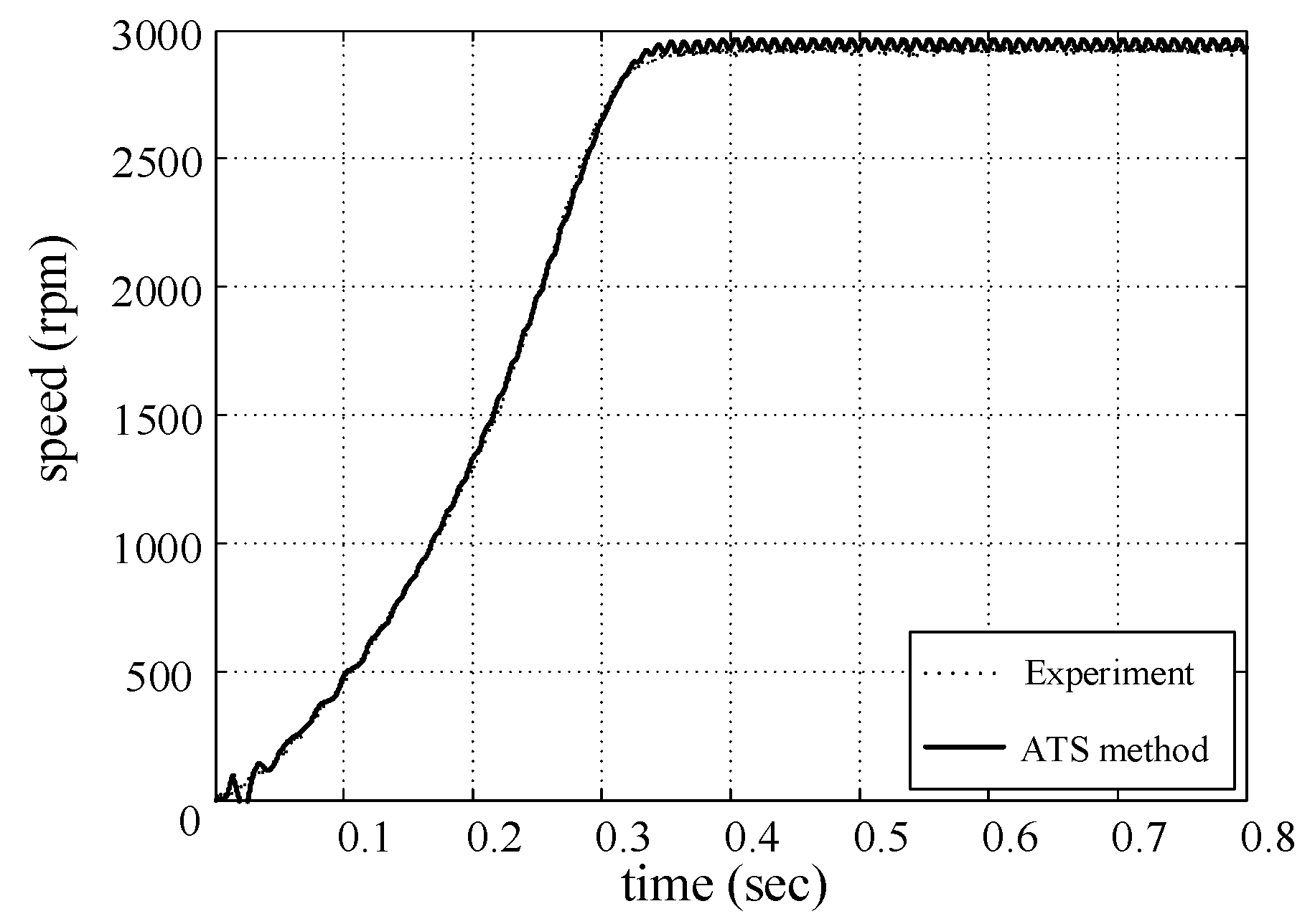
Figure 5.
The equivalent circuit of a capacitor-run single-phase induction motor.
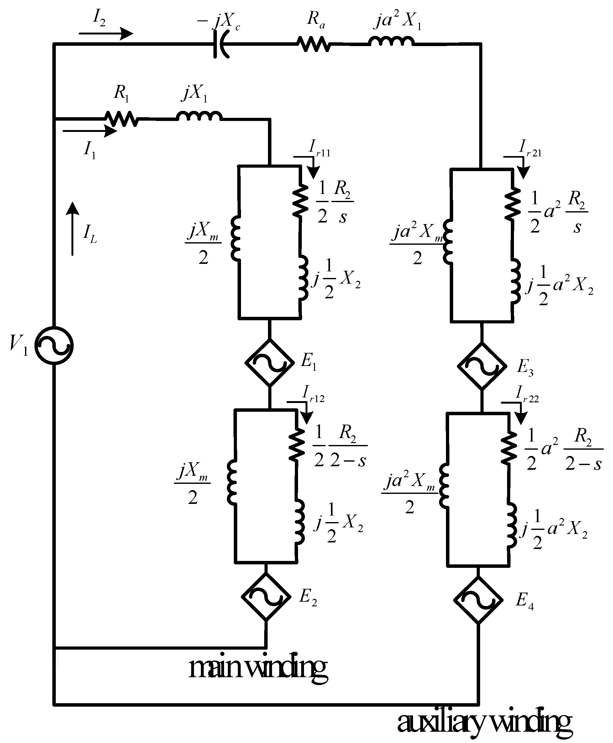
Figure 6.
The optimal frequency for loss minimization at any speed.
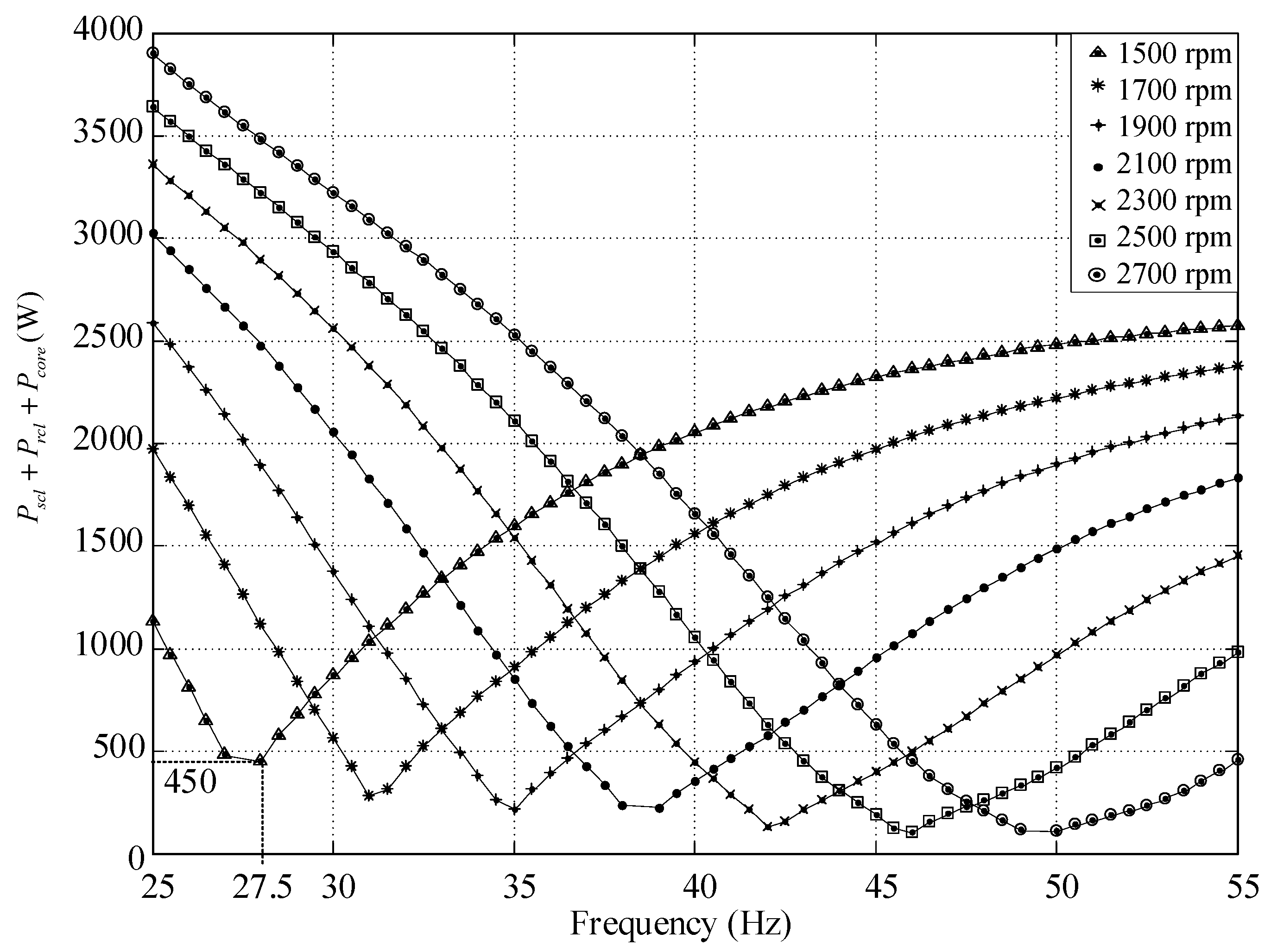
Figure 7.
Input membership function.
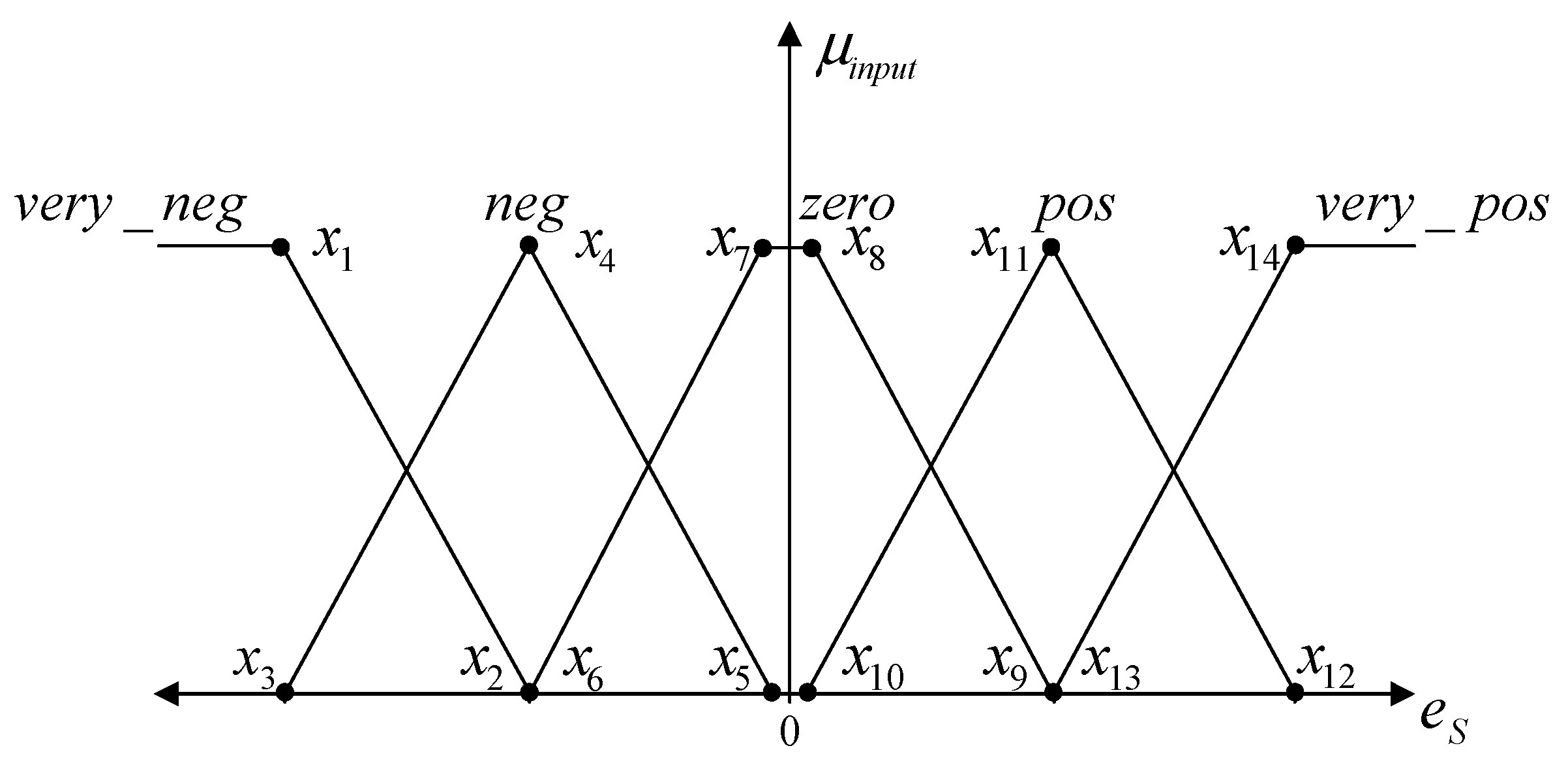
Figure 8.
Output membership function.

Figure 9.
Actual and reference speeds.
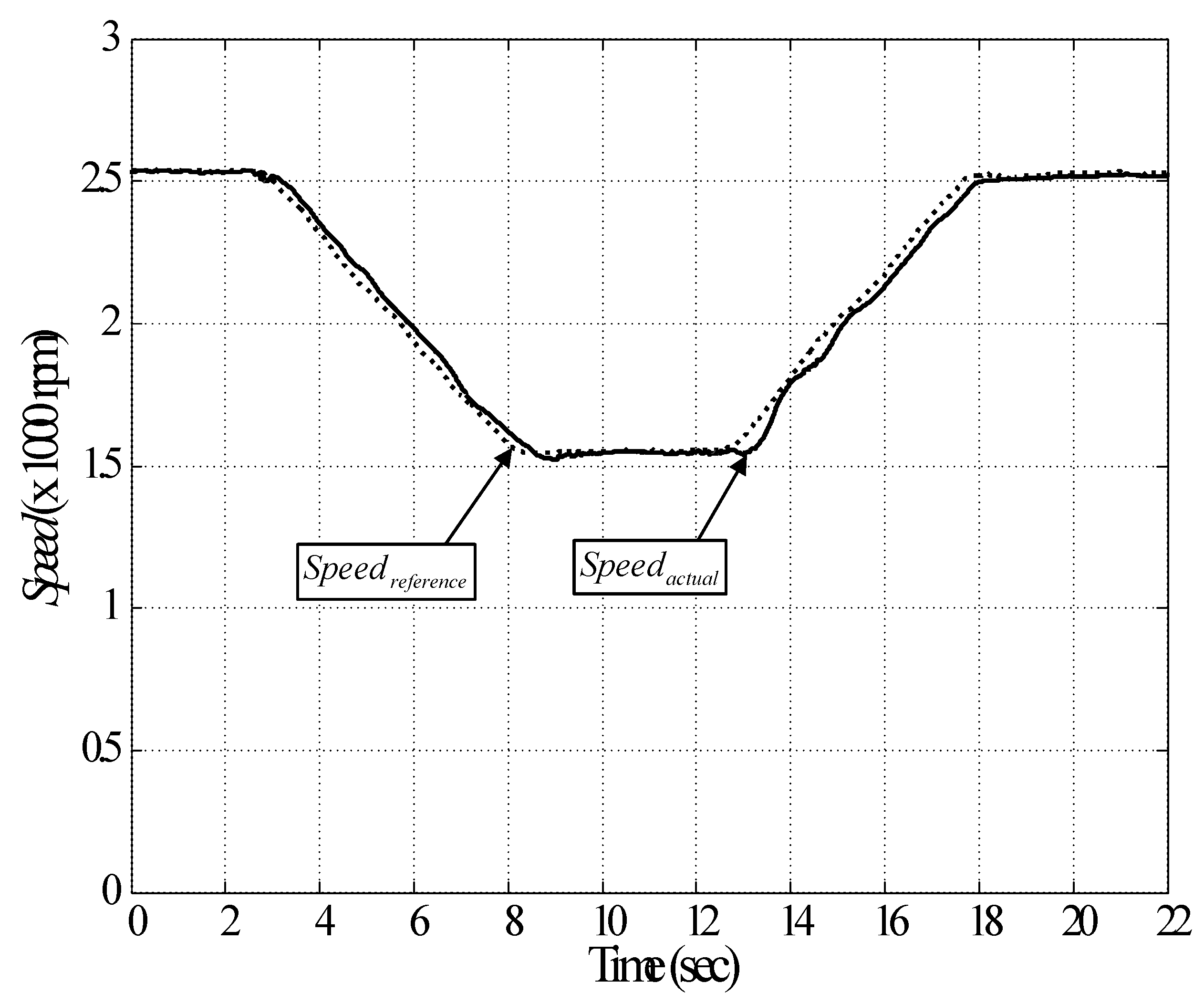
Figure 10.
Testing rig for the energy-saving approach.
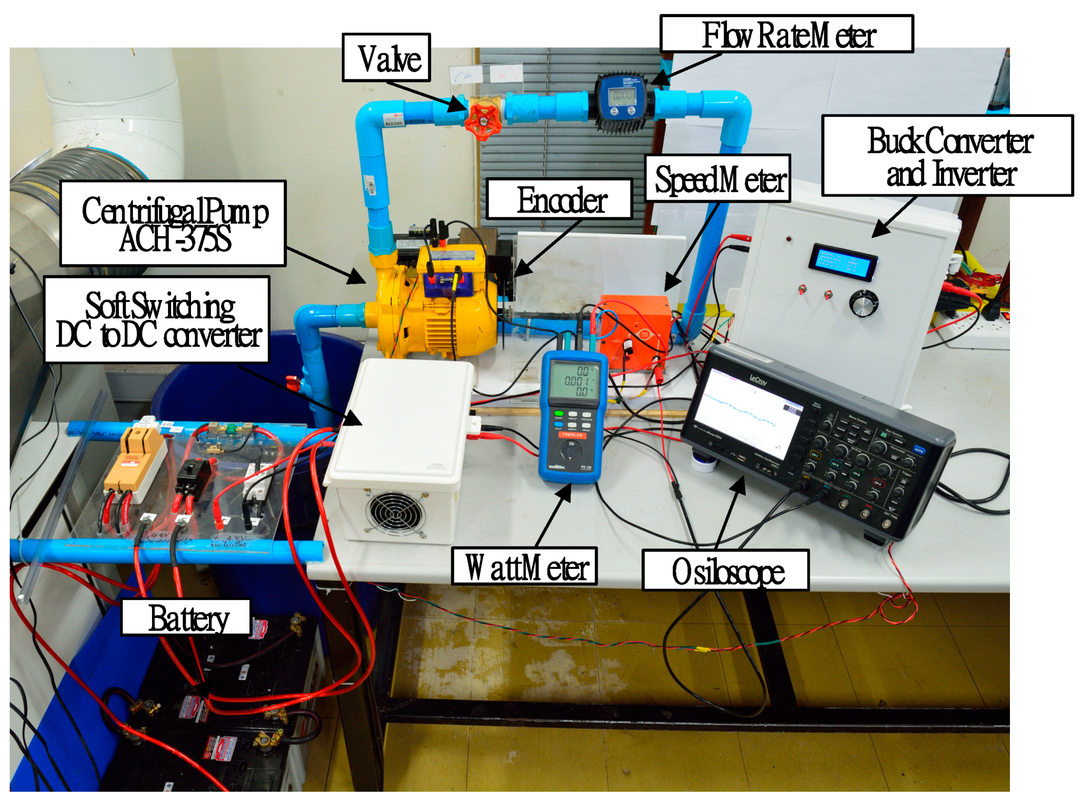
Figure 11.
Experimental result for the energy-saving approach, (a) Input power, (b) Power factor.

Table 1.
Parameters of the single-phase induction motor.
| Parameters | Searching Interval | Identified Value Using ATS |
|---|---|---|
| L1 | [0.01744 0.02131] | 19.30 × 10⁻³ |
| R2 | [0.01161 0.01419] | 13.26 |
| L2 | [0.01744 0.02131] | 19.50 × 10⁻³ |
| Lm | [0.35 0.43] | 0.40 |
| La | [0.02131 0.02604] | 24.20 × 10⁻³ |
| J | [0.0001 0.005] | 0.0016 |
Table 2.
Linguistic variables and linguistic values.
| State | Linguistic Variables | Linguistic Values | Definition |
|---|---|---|---|
| Input | es (speed error value) | very_neg (very negative) | Speedreference << Speedactual |
| neg (negative) | Speedreference < Speedactual | ||
| zero | Speedreference = Speedactual | ||
| (positive) | Speedreference > Speedactual | ||
| (very positive) | Speedreference >> Speedactual | ||
| Output | d (duty cycle) | very decrease | |
| decrease | |||
| constant | |||
| increase | |||
| very increase |
Table 3.
Input and output membership function parameters.
| Input Membership Function | |||||||||||||||||
|---|---|---|---|---|---|---|---|---|---|---|---|---|---|---|---|---|---|
| −300 | −300 | −300 | −300 | −300 | −150 | −10 | 10 | 150 | 10 | 150 | 300 | 150 | 300 | ||||
| Output membership function | |||||||||||||||||
| 10 | 10 | 10 | 10 | 10 | |||||||||||||
Publisher’s Note: MDPI stays neutral with regard to jurisdictional claims in published maps and institutional affiliations. |
© 2021 by the authors. Licensee MDPI, Basel, Switzerland. This article is an open access article distributed under the terms and conditions of the Creative Commons Attribution (CC BY) license (https://creativecommons.org/licenses/by/4.0/).
Share and Cite
MDPI and ACS Style
Suwongsa, T.; Areerak, K.; Areerak, K.; Pakdeeto, J. Energy Saving Approach for an Electric Pump Using a Fuzzy Controller. Energies 2021, 14, 3330. https://doi.org/10.3390/en14113330
AMA Style
Suwongsa T, Areerak K, Areerak K, Pakdeeto J. Energy Saving Approach for an Electric Pump Using a Fuzzy Controller. Energies. 2021; 14(11):3330. https://doi.org/10.3390/en14113330
Chicago/Turabian StyleSuwongsa, Tuchapong, Kongpol Areerak, Kongpan Areerak, and Jakkrit Pakdeeto. 2021. "Energy Saving Approach for an Electric Pump Using a Fuzzy Controller" Energies 14, no. 11: 3330. https://doi.org/10.3390/en14113330
Note that from the first issue of 2016, this journal uses article numbers instead of page numbers. See further details here.