Case of Study of the Electrification of a Tractor: Electric Motor Performance Requirements and Design


Department of Industrial Engineering, University of Padova, Via Gradenigo 6/a, 35131 Padova, Italy
*
Author to whom correspondence should be addressed.
Energies 2020, 13(9), 2197; https://doi.org/10.3390/en13092197
Submission received: 9 April 2020
/
Revised: 27 April 2020
/
Accepted: 29 April 2020
/
Published: 2 May 2020
Abstract
:The focus of this paper is the potential electrification of specialized agricultural tractors involved in vineyards and orchards. This category of machinery has not received research attention to date; however, regulations are encouraging lower emissions and higher efficiency, requiring the adoption of new technologies. Traction makes up only a limited part of this application, and the working cycle is not trivial; therefore, the design of the system is not straightforward. This study takes advantage of experimental measurements carried out under real operating conditions on a traditional specialized tractor, which was chosen as performance target. The performance requirements of the hybrid powertrain components are investigated, with particular focus placed on the electric motor. According to the dimension constraints, the design of the electric motor is carried out considering the requirements in terms of its thermal-equivalent torque and overload capability. The results are validated through a detailed thermal simulation under real duty cycles.
1. Introduction
In recent years, there has been increasing attention paid to the electrification of non-road mobile machinery, with a particular focus on the machinery involved in construction and agricultural applications [1]. There has also been increasing interest in the introduction of stricter regulations for Internal Combustion Engine (ICE) installed in non-road mobile machinery, which requires lower emissions and higher efficiency. The European Union (EU) regulation [2] sets five emission classes, which are categorized into “Stages I…V”; from 2020, all power size engines must meet Stage V requirements. These new limits require the adoption of additional components (i.e., Selective Catalytic Reduction (SCR), Diesel Exhaust Fluid (DEF) tanks, Diesel Particulate Filters (DPF)), making the structure and control of ICE more complex.
In the category of construction machinery, various types of solutions have been proposed, such as the electrification of the drive train or the electrification of the hydraulic system [3,4], and some solutions have been already adopted in commercialized machinery. In the case of agricultural machinery—in particular, for agricultural tractors—electrification is still at an initial stage. Some studies have been carried out including a feasibility evaluation of full-electric vehicles, the electrification of auxiliaries, and traction electrification with in-wheel motors [5,6,7].
Specialized tractors are a particular category of agricultural tractors which are involved in vineyard and orchard applications. The limited dimensions of the crops set strict constraints for the width and height of specialized tractors; this is often in contrast to the high power required by heavy applications and makes electrification challenging. As an example, the typical dimensions for such a tractor category are a width of 1500 , height of 1800 and wheelbase of 2000 . This machinery is involved in a wide variety of operations with different intensities; therefore, there is increasing interest in electrification, as the powertrain could achieve better versatility. For example, the hybrid powertrain could fulfill heavy operation requirements by combining the power of ICE and Electric Machine (EM). Moreover, the proper power management of the load point of ICE and EM would allow better efficiency to be achieved for the overall system. On the other hand, working in pure electric mode only with the EM could be sufficient for light operations. This latter case brings interesting benefits, such as the reduction of local emissions on crop fields or inside greenhouses, as well as the reduction of noise and vibration, improving the comfort and health of operators. Other studies regarding the advantages in terms of the consumption and working autonomy have been carried out [8,9].
The research into the road-vehicle category is already at an advanced stage [10,11,12], including verified models which are useful for system sizing and well-known driving cycles. However, in the case of agricultural tractors, the traction is only a limited part of the machine [13]; the power required by the Power Take Off (PTO) for implementation and the pump for hydraulic circuits has to be considered, which makes the vehicle model more complex.
The purpose of this paper is to present a case of study for the sizing process of an EM, which is required for the electrification of a specialized tractor with a power rating of 100 . As previously stated, this is not straightforward for this kind of vehicle. Recent studies regarding the design of Permanent Magnet (PM) motors for agricultural tractors have been carried out [14,15], in which the EM was designed for the peak performance required by the tractor. In this case study, the design was carried out considering the thermal-equivalent torque. This strategy allowed us to reduce the dimensions of EM, improving the feasibility of the electrification of specialized tractors. The design of the EM was carried out by means of Finite-Element Analysis (FEA) [16,17,18], and the design was validated through a detailed thermal analysis of the EM. The design of other components required by the electric system (i.e., the battery and power converter) is not within the scope of this project; it is supposed that there are commercial solutions which are able to satisfy their performance and dimension requirements.
2. Powertrain Electrification
This section reports the purpose of the electrification and the related constraints in order to clarify the strategy adopted in the project.
2.1. Electrification Purpose and Constraints
The purpose of this project is the design of an hybrid tractor for specialized applications with a total rated power of 100 . This rated power is approximately the highest power available within the dimension constraints of specialized tractors.
We begin with a traditional specialized tractor, powered by a 74 ICE, which is replaced by a downsized ICE in the hybrid powertrain with a power rating of . In Figure 1, the performance of the two ICEs are compared. The maximum torque developed by the ICE is 280 ; instead, the 74 ICE develops a maximum torque of 404 . The EM requires a proper design in order to fill the gap between the two ICEs for the entire speed range.
According to the EU regulation, the downsized engine has been chosen within the Stage V emission class. Moreover, this regulation sets less restrictive limits in the case of an ICE with a power rating lower than 56 .
2.2. Traditional Powertrain
Agricultural tractors are often involved in a wide variety of operations and require a more complex powertrain compared to automotive applications. Figure 2 shows a traditional powertrain schema including the main components; this architecture is obtained from [9,13].
The powertrain is powered by an ICE—in this case, with a rated power of 74 . The mechanical loads are connected to the ICE through three shafts, called , and in Figure 2.
- The shaft connects the pump to operate the hydraulic oil circuit; this is required for hydraulic steering and hydraulic lifting. Moreover, there are instruments which need to be connected with the tractor hydraulic circuit.
- The shaft is required to power external instruments through the PTO. This shaft is connected to the ICE with a speed reducer. The clutch allows the shaft to be decoupled if not required.
- The shaft provides power to the rear wheel axle for traction, and eventually also to the front axle in the case of 4WD traction. The schema shows the clutch and a gearbox.
The feature of mechanical transmission in agricultural tractors is worthy of note and is a current topic of research [21]. Transmissions for agricultural tractors have a much higher number of speed ratios compared to road vehicles. These are required to provide optimal speed–torque combinations for the operation of different instruments under variable operating conditions. Moreover, it must be possible to reach the top speed in road transportation (i.e., 45 /). A particular situation in specialized tractors is vineyard or orchard maintenance (i.e., tipping machine applications); these operations require higher precision in order to avoid plant damage, and these operations are therefore carried out at limited speed (i.e., lower than 1 /) while the ICE works at very low torque.
2.3. Hybrid Powertrain
The objective considered for the design of the hybrid powertrain is to fulfill the same requirements as a traditional powertrain. The downsized ICE was already chosen among the commercial solutions; instead, the EM was designed according to the specifications of the sizing process. For this reason, a parallel architecture was preferred; Figure 3 shows the considered schema obtained from [9]. The architecture is as similar as possible to a traditional powertrain. The first noticeable difference is the electric system, which includes an electric motor, inverter and battery. An additional clutch is considered, , which allows the ICE to be decoupled from the powertrain. This feature is required to operate the powertrain with the EM in pure electric mode when possible.
In this hybrid powertrain, the pump shaft for the hydraulic circuit was not included; it was preferable to supply the pump with a dedicated electric motor. This choice was a consequence of the hydraulic circuit duty cycle. Wheel steering requires the frequent usage of the hydraulic circuit with low power; an opposite example is the rear lift, which requires high power to lift heavy implements and is not frequently used. Similar examples could be reported for applications using the hydraulic circuit. Therefore, the pump duty cycle is intermittent and subject to variable intensity.
In a traditional powertrain, as shown in Figure 2, the pump is constantly connected to the ICE and subject to modest power losses [13]. By powering this pump with a dedicated electric motor, the overall system could achieve better efficiency; however, the electric motor requires proper design in order to achieve the best efficiency on the pump duty cycle. A detailed study of the electrification of oil pumps is presented in [4] for the case of construction machinery, where these pumps are widely used.
3. Hybrid-Powertrain Performance Investigation
As introduced in Section 2, the hybrid powertrain with a downsized ICE has to achieve a similar performance to the traditional tractor considered as a reference. Therefore, the performance required by the electric motor needs to be investigated. For this purpose, the reference traditional tractor was tested in an exhaustive experimental process under several working conditions for specialized tractors. In Table 1, the working conditions are listed and divided into different duty cycle intensities.
The target tractor was provided with the required speed and torque sensors. These were installed in the ICE shaft in order to include power losses due to transmissions. The measured loads for the purposes of this project were the torque to the traction and to the PTO. In each operation listed in Table 1, the proper instrument/trailer was installed on the tractor, and the test was carried out in a real vineyard/orchard by an expert tractor driver. The duration of each test was longer than one hour, and the test included the operation of changing direction at the end of the crop line.
3.1. Power-Management Strategy
This analysis requires a proper power-management strategy in order to handle the working points of ICE and EM. As the initial stage in the process of agricultural tractor electrification, it was preferable to consider simplified rule-based power-management with a Charge-Depleting (CD) strategy and plug-in battery re-charging [22,23]. The rules implemented for the hybrid driving mode were as follows:
where the total amount of torque request is , considering the traction torque () and PTO torque () demand. As illustrated, hybrid mode EM is turned on when the torque request overtakes the ICE limit . In the case of full electric mode operation, when possible, ICE is turned off and the powertrain is powered only by EM ().
The agricultural tractor architecture adopted for this project is of the plug-in recharge type, meaning that the battery recharging can be performed from the electric grid. Negative torque is not considered for battery energy regeneration due its negligible contribution in such an application.
3.2. Electric Motor Performance
A non-trivial aspect of the design is the precise definition of the torque requirements for the EM. The analysis of the required performance was carried out by means of torque balance, according to the power-management strategy in Equation (1). The torque loads and are taken from the results of the experimental measurements of the reference traditional tractor. Instead, the downsized ICE torque limit is derived from the characteristic in Figure 1b, as a function of the measured shaft speed.
The relevant duty cycles for sizing the electric motor are those classified as heavy cultivation in Table 1. In this case, the powertrain works at maximum performance; therefore, the EM exhibits its most intensive duty cycle in order to boost the ICE. Figure 4a reports the torque required by the EM when the hybrid tractor is operated with a weeder instrument, and Figure 4b reports the shaft speed. These results show that the EM has to deliver a peak torque of 150 .
An interesting further analysis is the evaluation of the capability to operate the tractor in pure electric mode; for example, for those operations classified as light cultivation. In this case, ICE is not considered and EM provides the full torque required. The results in terms of torque and speed required for the EM are reported in Figure 5. It is worthy of note that the maximum torque required is about 110 , which is lower than the torque required by a weeder in hybrid mode.
3.3. Equivalent Thermal Torque
The results in Figure 4a and Figure 5a are characterized by an intermittent torque request, with a decreasing frequency for higher peak torque values. For the design of the EM, besides the instantaneous maximum torque (), it is convenient to consider the thermal-equivalent torque (), which is defined by the thermal behavior of the EM.
In order to obtain the thermal-equivalent torque, a simplified thermal analysis is first introduced. Figure 6 shows a simplified thermal circuit, adopting the electric analogy, where and are the global thermal resistance and capacitance, respectively; the resulting over-temperature is . The only heat source considered is the stator-winding joule loss , since it is the main heat source and is most difficult to dissipate.
This circuit can be solved by adopting the Laplace transformation as follows:
and introducing a quantity called the thermal-equivalent power loss ,which can be described by the following expressions:
where is the EM thermal time-constant.
The first equation gives the steady-state final temperature, while the second equation handles the transient behavior of EM. It is worth noting that represents a low-pass filter with a cut-off frequency of . Applying this filter to the instantaneous power losses allows us to find the related thermal-equivalent power losses .
The stator-winding Joule losses of EM are computed as follows:
where is the phase resistance and i the phase current. The electromagnetic torque equation is
where is the torque constant of the electric motor assuming Surface Permanent Magnet (SPM) machines. Substituting (6) in (5), the Joule losses are expressed as
This expression highlights that Joule losses change with the square of the torque. Using (4), it is then possible to identify an equivalent torque as
which allows us to define the thermal-equivalent torque, which is useful for sizing the EM, from the instantaneous torque . Figure 7 shows a block diagram for the computation of .
The results reported in Section 3.2, which are given as instantaneous torque , are processed in order to investigate the consequent thermal-equivalent torque , adopting the procedure reported in Figure 7, with a thermal time-constant of 200 s, which is a reasonable value for a liquid-cooled EM. The EM thermal-equivalent torque resulting from the weeder analysis in hybrid mode is reported in Figure 8a; the resulting thermal-equivalent torque from the plant lifting plough in pure electric mode is reported in Figure 8b. The first case shows the thermal-equivalent torque within 30 ; for the second case, the thermal-equivalent torque is within 35 . It should be noted that in the case of pure electric operation, the instantaneous torque has to exhibit both intermittent and continuous components, as shown in Figure 5a. Therefore, the resulting thermal-equivalent torque shows a minor oscillation.
4. Design of the Electric Motor
The analysis presented in the previous section fulfilled the purpose of investigating the performance requirements for the electric motor. As reported for the most significant duty cycles, the designed thermal-equivalent torque of the EM is about 35 , with a instantaneous deliverable torque of at least 150 which means an overloading capability of about 5 times. The EM is designed for this application in order to fulfill the performance requirements. This section reports the details of the designed EM; moreover, the thermal limits are verified.
4.1. Data and Performance
In hybrid powertrain applications, one of the main constraints regarding electric motors is the maximization of the torque density. In the case of this project, the EM is installed between the ICE and the transmission; therefore, it is preferred to achieve a short stack length (i.e., lower than 200 mm). For these reasons, an EM with a PM has been preferred, which allows a higher torque density compared to other electric motor typologies; moreover, it is provided with a liquid-jacket for cooling, allowing better performance. As reported in Figure 3, the hybrid powertrain has the same gearbox as the traditional powertrain. For this reason, the EM is not required to have a particular flux-weakening capability (i.e., constant power at high speed).
In recent years, in the field of electric motors for automotive applications, different solutions have been proposed, such as axial flux machines [26,27] or fractional slot machines [28]. However, in order to reduce the manufacturing cost, a traditional configuration has been adopted. In particular, stator lamination is a widespread geometry for industrial electric motors, which also allows the adoption of a commonly available winding machine. The rotor is of the SPM type, which allows a simplified manufacturing process and a simple lamination cut.
The main data of the designed EM are reported in Table 2. The rated torque is 40 , which is slightly higher than the specification. This value has been verified by means of a thermal analysis supplying the EM at rated torque and speed. The overload torque capability of 150 was verified by means of FEA in order to avoid PM demagnetization. The winding is designed for a rated speed of 2600 , which is the speed range of the downsized ICE. The line-to-ground peak voltage is 400 , which corresponds to a converter with a 700 DC-bus. Figure 9 reports the winding voltage and current maps as a function of the mechanical speed and torque. The current depends upon the produced torque. Instead, the voltage depends on the mechanical speed and the current due to the voltage drop of the stator resistance. These results allow us to choose the inverter power size. The maximum apparent power required is about 62 when the EM is operated at maximum speed and torque; i.e., EM is supplied at the 400 peak and peak. However, it is worthwhile to consider a proper design for the inverter as well based on a compromise between the rated performance and overload capability.
Figure 10 reports the EM flux density plot at maximum overload conditions, computed by means of FEA, and the layout of the structure in a longitudinal section. The layout shows the liquid channels in the external motor housing with a helicoidal shape. The channel-closing sheet, with holes for the inlet and outlet of the liquid, is not included in the figure. As reported in Table 2, this EM is characterized by a wide diameter compared to the stack length and a low number of poles. Therefore, the Joule losses in the end-winding part are higher than the Joule losses in the copper inside slots. Since the heat produced in the end-winding is the most difficult to dissipate, this part was encapsulated with a thermally conductive epoxy resin, which has a good thermal conductivity (i.e., /).
Considering the thermal-equivalent torque for the design of the EM allows us to reduce the machine volume. This approach consists of setting the rated torque of EM to equal that of the thermal-equivalent torque required in a specific duty cycle. A simple comparison could be done by assuming that the rated torque is set as equal to the peak torque required in a specific duty cycle; i.e., 150 . Since the torque varies linearly with the stack length, using the same 2D geometry, this EM—with a rated torque of 40 —will achieve a rated torque of 150 if the stack length is increased 3.75 times. Therefore, in the case of a rated torque of 150 the stack length required is . This is much greater than the result achieved in this project, where it has been highlighted that a rated torque of 40 is sufficient to fulfill the duty cycles; the stack length is 65 . The analysis of the thermal-equivalent torque is a common approach in the design of electric motors for road vehicles; however, this has not yet been thoroughly investigated in the case of agricultural tractors. In order to validate these results, the EM thermal behavior is analyzed through a dynamical thermal network.
4.2. Thermal Analysis of the Electric Motor
The design of the electric motor has been carried out under certain hypotheses regarding the thermal performance. In particular, the current density was chosen from among the reasonable values (i.e., for a liquid-cooled EM [29]), while the thermal time-constant was supposed to be 200 . The expected result is that the EM, during a complete duty cycle with variable mechanical load, reaches a maximum temperature within the limits; i.e., 145 for the F class.
In order to verify the mentioned constraints, a thermal network was developed and simulated under the real duty cycle of the EM [30]. The thermal network is illustrated in Figure 11 adopting the electric circuits analogy; a detailed explanation is reported in [31,32]. The heat sources are divided into Joule losses in slot winding , Joule losses in end-windings , iron losses in the stator tooth and iron losses in the stator back iron . The heat produced in the slot is dissipated toward the stator lamination through the conductor insulation and the slot liner. These are the resin layer—represented by the thermal resistance —and the paper sheet in the slot between the conductors and stator laminations. The latter is divided into the lateral-side insulation of the slot (between conductors and tooth) and the upper-side insulation (between conductors and back-iron); the respective resistances are indicated as and . The iron thermal resistances are indicated as and , respectively, for the tooth and back-iron, also including the thermal capacitances. The heat dissipation through the liquid-jacket has been considered with an equivalent resistance. The heat in the end-winding is dissipated either through the slot or through the liquid-jacket. The first case is regulated through the longitudinal thermal-resistance of the copper conductors, while the second is modeled with the resistance for the conductor’s insulating layer and the resistance for the encapsulating epoxy resin . The relevant thermal capacitances are included, adopting similar subscripted acronyms to those of the resistances. The rotor is not considered in the thermal network; it can be properly designed to limit the contribution of rotor losses [33,34].
The loss sources, as an input of the thermal network, are computed from the simulations as a function of the instantaneous speed and torque of the EM, as reported in Figure 12. As expected, the iron losses mainly depend upon the mechanical speed and upon the current. The Joule losses are only due to the current intensity, and therefore they depend upon the toque. During the simulation of the thermal network, the Joule losses are updated according to the actual winding temperature. As previously stated, the Joule losses weigh more than iron losses and, in this case, the end-winding part exhibits higher losses than the winding part in the slot.
The thermal network simulations have been carried out supposing that the EM operates under real duty cycles. In each simulation time-step, the instantaneous torque and speed are given as in Figure 4 and Figure 5; through the loss maps in Figure 12, the loss source references to the thermal network are given. The thermal duty cycle has been simulated both for the weeder case in hybrid mode and the plant lifting plough in pure electric mode; the results are reported in Figure 13 for the different machine parts. It is worthy of note that the temperature during the duty cycle is always lower than 110 . The most critical part for heat dissipation is the end-winding; the temperature evolution follows the previously predicted thermal-equivalent torque, with higher peaks in the case of the plant lifting plough.
The hypothesized thermal time-constant has been verified by simulating the temperature transience when the EM is operated at the rated torque and speed.
4.3. Efficiency Map
The electric motors used in agricultural tractors, as well as those in road vehicles, work in a wide region of the speed–torque plane. Therefore, it is interesting to evaluate the EM’s performance through its efficiency map in this working region. Figure 14 shows the efficiency map of the designed EM, which is reported either in the speed–torque plane or the speed–power plane. The efficiency in each working point is computed from the losses maps shown in Figure 12.
The upper contour of the speed–torque maps in Figure 14a corresponds to the overload limit, which is 150 up to the rated speed. The resulting mechanical power is computed as
where is the mechanical torque and the mechanical speed in .
The dashed lines show the rated performance in terms of the mechanical speed ( 2600 ) and mechanical torque ( 40 ). The corresponding mechanical power rated limit is a function of the speed. The best efficiency region, which is 92%, is located in the neighborhood of the rated working point (indicated as in the figures). Comparing the instantaneous performance requirements reported in Figure 4 and Figure 5, it is worthy of note that the best efficiency region corresponds to the most frequent location of the duty cycle working points (speed–torque). This a positive consequence of adopting a proper rated torque for the design of EM.
The efficiency map of the EM allows us to analyze the electric energy required in a variable duty cycle. A similar consumption map could be found for the ICE. A study on the consumption evaluation and the consequent advantages of such an application is presented in [8].
5. Conclusions
This paper focused on the electrification of agricultural specialized tractors for application in vineyards and orchards. In this category of machine, the electrification process is challenging due to the dimension constraints set by narrow crops. However, the recent introduction of strict emission regulations has increased the interest in new technologies. In agricultural tractors, traction is only a limited part of the workload; power take-off and a hydraulic circuit are also required. Therefore, the sizing of the system is not trivial, and the workloads are not yet well defined.
This project aimed to design an electric motor for a hybrid powertrain. The performance requirements were investigated through the results of an experimental measurement procedure carried out on a traditional tractor with the target performance. The exhaustive post-processing of these measurements highlighted that the torque required by the electric motor was intermittent; the thermal-equivalent torque was much lower compared to the peak torque requirements. Consequently, the adoption of a proper design based on the thermal-equivalent torque allowed us to reduce the electric motor’s dimensions. This is a considerable advantage for applications in which a compromise between high power and limited space must be reached, as is the case for specialized tractors. The designed electric motor has been verified by means of finite elements simulations, and a lumped-parameters thermal-network was adopted to simulate operation in real duty cycles.
As an initial stage in an are which has not received sufficient attention so far—compared to the focus placed on road vehicles—the architecture was kept as similar as possible to a traditional powertrain. A downsized internal combustion engine was chosen among the commercialized options; additionally, for the electric motor, commonly available components were preferred. Moreover, the designed electric motor allowed us to reduce production costs, due to the consolidated experience of manufacturers regarding the surface permanent magnet-mounted motor. Therefore, this project could form a basis for further improvements.
Author Contributions
Conceptualization, D.T. and L.A.; methodology, D.T. and L.A.; validation, D.T. and L.A.; formal analysis, D.T.; investigation, D.T.; resources, L.A.; data curation, D.T.; writing–original draft preparation, D.T.; writing–review and editing, D.T. and L.A.; supervision, L.A.; funding acquisition, L.A. All authors have read and agreed to the published version of the manuscript.
Funding
This work has been developed within the scope of project “green-seed” ID 2017SW5MRC founded by MIUR within the PRIN-2017 call.
Conflicts of Interest
The authors declare no conflict of interest.
References and Note
- Lajunen, A.; Sainio, P.; Laurila, L.; Pippuri-Mäkeläinen, J.; Tammi, K. Overview of Powertrain Electrification and Future Scenarios for Non-Road Mobile Machinery. Energies 2018, 11, 1184. [Google Scholar] [CrossRef] [Green Version]
- Regulation (EU) 2016/1628 of the European Parliament and of the Council of 14 September 2016 on requirements relating to gaseous and particulate pollutant emission limits and type-approval for internal combustion engines for non-road mobile machinery, amending Regulations (EU) No 1024/2012 and (EU) No 167/2013, and amending and repealing Directive 97/68/EC.
- Grammatico, S.; Balluchi, A.; Cosoli, E. A series-parallel hybrid electric powertrain for industrial vehicles. In Proceedings of the 2010 IEEE Vehicle Power and Propulsion Conference, Lille, France, 1–3 September 2010; pp. 1–6. [Google Scholar]
- Mendes, F.E.G.; Brandao, D.I.; Maia, T.; Braz de Filho, J.C. Off-Road Vehicle Hybridization Methodology Applied to a Tractor Backhoe Loader. In Proceedings of the 2019 IEEE Transportation Electrification Conference and Expo (ITEC), Detroit, MI, USA, 19–21 June 2019; pp. 1–6. [Google Scholar]
- Brenna, M.; Foiadelli, F.; Leone, C.; Longo, M.; Zaninelli, D. Feasibility Proposal for Heavy Duty Farm Tractor. In Proceedings of the 2018 International Conference of Electrical and Electronic Technologies for Automotive, Milan, Italy, 9–11 July 2018; pp. 1–6. [Google Scholar]
- Barthel, J.; Gorges, D.; Bell, M.; Munch, P. Energy Management for Hybrid Electric Tractors Combining Load Point Shifting, Regeneration and Boost. In Proceedings of the 2014 IEEE Vehicle Power and Propulsion Conference (VPPC), Coimbra, Portugal, 27–30 October 2014; pp. 1–6. [Google Scholar]
- Zhitkova, S.; Felden, M.; Franck, D.; Hameyer, K. Design of an electrical motor with wide speed range for the in-wheel drive in a heavy duty off-road vehicle. In Proceedings of the 2014 International Conference on Electrical Machines (ICEM), Berlin, Germany, 2–5 September 2014; pp. 1076–1082. [Google Scholar]
- Troncon, D.; Alberti, L.; Mattetti, M. A Feasibility Study for Agriculture Tractors Electrification: Duty Cycles Simulation and Consumption Comparison. In Proceedings of the 2019 IEEE Transportation Electrification Conference and Expo (ITEC), Detroit, MI, USA, 19–21 June 2019; pp. 1–6. [Google Scholar]
- Troncon, D.; Alberti, L.; Bolognani, S.; Bettella, F.; Gatto, A. Electrification of agricultural machinery: A feasibility evaluation. In Proceedings of the 2019 Fourteenth International Conference on Ecological Vehicles and Renewable Energies (EVER), Monte-Carlo, Monaco, 8–10 May 2019; pp. 1–7. [Google Scholar]
- Bilgin, B.; Magne, P.; Malysz, P.; Yang, Y.; Pantelic, V.; Preindl, M.; Korobkine, A.; Jiang, W.; Lawford, M.; Emadi, A. Making the Case for Electrified Transportation. IEEE Trans. Transp. Electrif. 2015, 1, 4–17. [Google Scholar] [CrossRef]
- Rajashekara, K. Present Status and Future Trends in Electric Vehicle Propulsion Technologies. IEEE J. Emerg. Sel. Top. Power Electron. 2013, 1, 3–10. [Google Scholar] [CrossRef]
- Chan, C.C.; Bouscayrol, A.; Chen, K. Electric, Hybrid, and Fuel-Cell Vehicles: Architectures and Modeling. IEEE Trans. Veh. Technol. 2010, 59, 589–598. [Google Scholar] [CrossRef]
- Macmillan, R.H. The Mechanics of Tractor-Implement Performance: Theory and Worked Examples: A Textbook for Students and Engineers; University of Melbourne: Parkville, Australia, 2002. [Google Scholar]
- Seo, J.; Kim, Y.; Jung, I.; Jung, H. Permanent magnet synchronous motor for electric tractor of 35 horsepower. In Proceedings of the 2013 IEEE ECCE Asia Downunder, Melbourne, Australia, 3–6 June 2013; pp. 560–565. [Google Scholar] [CrossRef]
- Zhitkova, S.; Hameyer, K. Realization of a wide speed range for an agricultural tractor. In Proceedings of the 2016 XXII International Conference on Electrical Machines (ICEM), Lausanne, Switzerland, 4–7 September 2016; pp. 2031–2037. [Google Scholar] [CrossRef]
- Alberti, L.; Bianchi, N.; Morandin, M.; Gyselinck, J. Finite-Element Analysis of Electrical Machines for Sensorless Drives With High-Frequency Signal Injection. IEEE Trans. Ind. Appl. 2014, 50, 1871–1879. [Google Scholar] [CrossRef] [Green Version]
- Alberti, L.; Bianchi, N.; Bolognani, S. High Frequency d-q Model of Synchronous Machines for Sensorless Control. IEEE Trans. Ind. Appl. 2015, 51, 3923–3931. [Google Scholar] [CrossRef]
- Bottesi, O.; Alberti, L.; Sabariego, R.V.; Gyselinck, J. Finite Element Small-Signal Simulation of Electromagnetic Devices Considering Eddy Currents in the Laminations. IEEE Trans. Magn. 2017, 53, 1–8. [Google Scholar] [CrossRef]
- Engine Data-Sheet FPT N45 MSSX. Available online: https://www.fptindustrial.com/global/it/Pages/construction_nef45.aspx (accessed on 21 April 2020).
- Engine Data-Sheet DEUTZ TCD2.2 L3. Available online: https://www.deutz.com/en/products/engines/detail/442/ (accessed on 21 April 2020).
- Panzani, G.; Tanelli, M.; Savaresi, S.M.; Pirola, C.; Gavina, G.; Taroni, F. Transmission control for power-shift agricultural tractors. In Proceedings of the 2010 American Control Conference, Baltimore, MD, USA, 30 June–2 July 2010; pp. 2188–2193. [Google Scholar] [CrossRef]
- Wirasingha, S.G.; Emadi, A. Classification and Review of Control Strategies for Plug-In Hybrid Electric Vehicles. IEEE Trans. Veh. Technol. 2011, 60, 111–122. [Google Scholar] [CrossRef]
- Liu, W. Hybrid Electric Vehicle System Modeling and Control; John Wiley & Sons, Ltd.: Hoboken, NJ, USA, 2017. [Google Scholar] [CrossRef]
- Duty Cycle of the Electric Motor Driving a Weeder in Hybrid Mode. Available online: https://docs.google.com/document/d/e/2PACX-1vS7SpcbwXXuYrH3mdKuYEIxBPSqlZFueAgK7Q3QqZoa2P2IL_cHlbeetuGOuJG89ZLIaxdQZb8jwTp7/pub (accessed on 21 April 2020).
- Duty Cycle of the Electric Motor Driving a Plant Lifting Plough in Pure Electric Mode. Available online: https://docs.google.com/document/d/e/2PACX-1vTeL8ZezHadvITaSIYSj-SQduoc5RFFlFaGZkKHiLpKgA-V_vGmLYZqm2RXxWiyc_D7AN6qnVyZGE8I/pub (accessed on 21 April 2020).
- Deisenroth, D.; Ohadi, M. Thermal Management of High-Power Density Electric Motors for Electrification of Aviation and Beyond. Energies 2019, 12, 3594. [Google Scholar] [CrossRef] [Green Version]
- Kwon, T.S.; Sul, S.K.; Alberti, L.; Bianchi, N. Design and Control of an Axial-Flux Machine for a Wide Flux-Weakening Operation Region. IEEE Trans. Ind. Appl. 2009, 45, 1258–1266. [Google Scholar] [CrossRef]
- Bianchi, N.; Alberti, L.; Barcaro, M. Design and Tests of a Four-Layer Fractional-Slot Interior Permanent-Magnet Motor. IEEE Trans. Ind. Appl. 2016, 52, 2234–2240. [Google Scholar] [CrossRef]
- Ponomarev, P. Tooth-Coil Permanent Magnet Synchronous Machine Design for Special Applications. Ph.D. Thesis, Lappeenranta University of Technology, Lappeenranta, Finland, 2013. [Google Scholar]
- Fan, J.; Zhang, C.; Wang, Z.; Dong, Y.; Nino, C.E.; Tariq, A.R.; Strangas, E.G. Thermal Analysis of Permanent Magnet Motor for the Electric Vehicle Application Considering Driving Duty Cycle. IEEE Trans. Magn. 2010, 46, 2493–2496. [Google Scholar] [CrossRef]
- Boglietti, A.; Cavagnino, A.; Staton, D.; Shanel, M.; Mueller, M.; Mejuto, C. Evolution and Modern Approaches for Thermal Analysis of Electrical Machines. IEEE Trans. Ind. Electron. 2009, 56, 871–882. [Google Scholar] [CrossRef] [Green Version]
- Popescu, M.; Dorrell, D.; Alberti, L.; Bianchi, N.; Staton, D.; Hawkins, D. Thermal Analysis of Duplex Three-Phase Induction Motor Under Fault Operating Conditions. IEEE Trans. Ind. Appl. 2013, 49, 1523–1530. [Google Scholar] [CrossRef]
- Alberti, L.; Fornasiero, E.; Bianchi, N. Impact of the Rotor Yoke Geometry on Rotor Losses in Permanent-Magnet Machines. IEEE Trans. Ind. Appl. 2012, 48, 98–105. [Google Scholar] [CrossRef]
- Chiodetto, N.; Bianchi, N.; Alberti, L. Improved Analytical Estimation of Rotor Losses in High-Speed Surface-Mounted PM Synchronous Machines. IEEE Trans. Ind. Appl. 2017, 53, 3548–3556. [Google Scholar] [CrossRef]
Figure 1.
Powertrain performance comparison. The 74 kW [19] Internal Combustion Engine (ICE) of the traditional powertrain is considered as a project target; the downsized 55.4 kW [20] ICE is considered for the hybrid powertrain. These characteristics are obtained fromthe technical data sheets of two specific ICEs.

Figure 2.
Traditional powertrain architecture powered by the Internal Combustion Engine (ICE).

Figure 3.
Hybrid powertrain architecture powered by the Internal Combustion Engine (ICE) and the Electric Machine (EM).
Figure 3.
Hybrid powertrain architecture powered by the Internal Combustion Engine (ICE) and the Electric Machine (EM).

Figure 4.
Performance requirements for the Electric Machine (EM) as a boost for the Internal Combustion Engine (ICE) when the tractor is operated in hybrid mode with a weeder instrument. The numerical data are available in [24].
Figure 4.
Performance requirements for the Electric Machine (EM) as a boost for the Internal Combustion Engine (ICE) when the tractor is operated in hybrid mode with a weeder instrument. The numerical data are available in [24].
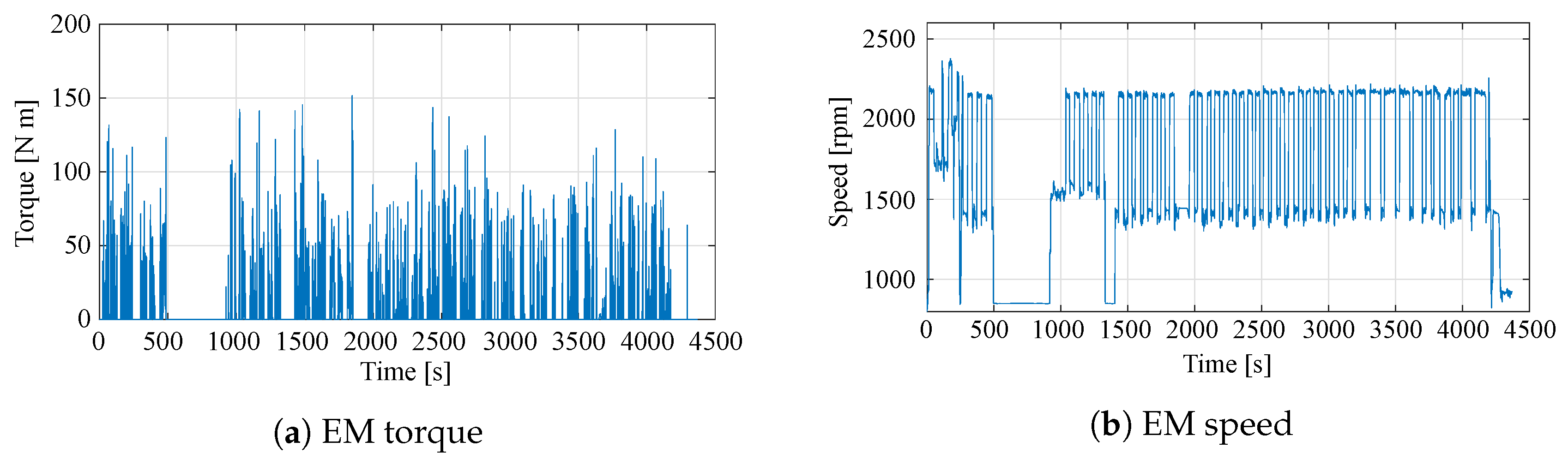
Figure 5.
Performance requirements for the Electric Machine (EM) when the tractor is operated in pure electric mode with a plant lifting plough instrument. The numerical data are available in [25].
Figure 5.
Performance requirements for the Electric Machine (EM) when the tractor is operated in pure electric mode with a plant lifting plough instrument. The numerical data are available in [25].
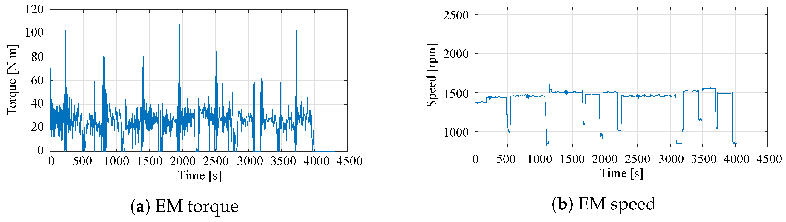
Figure 6.
Simplified thermal network of an electric motor.

Figure 7.
Example implementation of the torque filtering.

Figure 8.
Thermal-equivalent torque required by the electric motor for different instruments and driving modes.
Figure 8.
Thermal-equivalent torque required by the electric motor for different instruments and driving modes.

Figure 9.
Electric motor voltage and current at different working points.
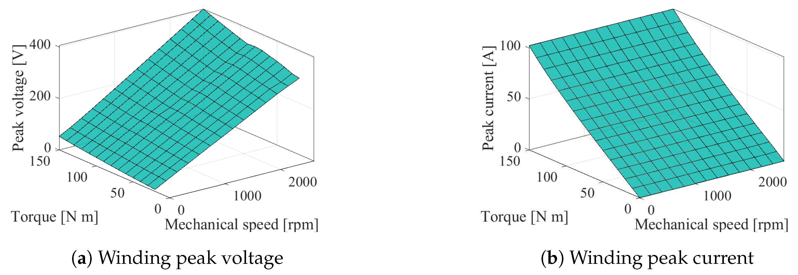
Figure 10.
Left: EM flux density plot and flux lines obtain by means of FEA. Simulation of the maximum overload working condition. Right: EM structure including encapsulated end-winding in the resin potting and the housing with a liquid-cooling jacket.
Figure 10.
Left: EM flux density plot and flux lines obtain by means of FEA. Simulation of the maximum overload working condition. Right: EM structure including encapsulated end-winding in the resin potting and the housing with a liquid-cooling jacket.

Figure 11.
Thermal network for the analysis of the dynamic thermal behavior of the electric motor.
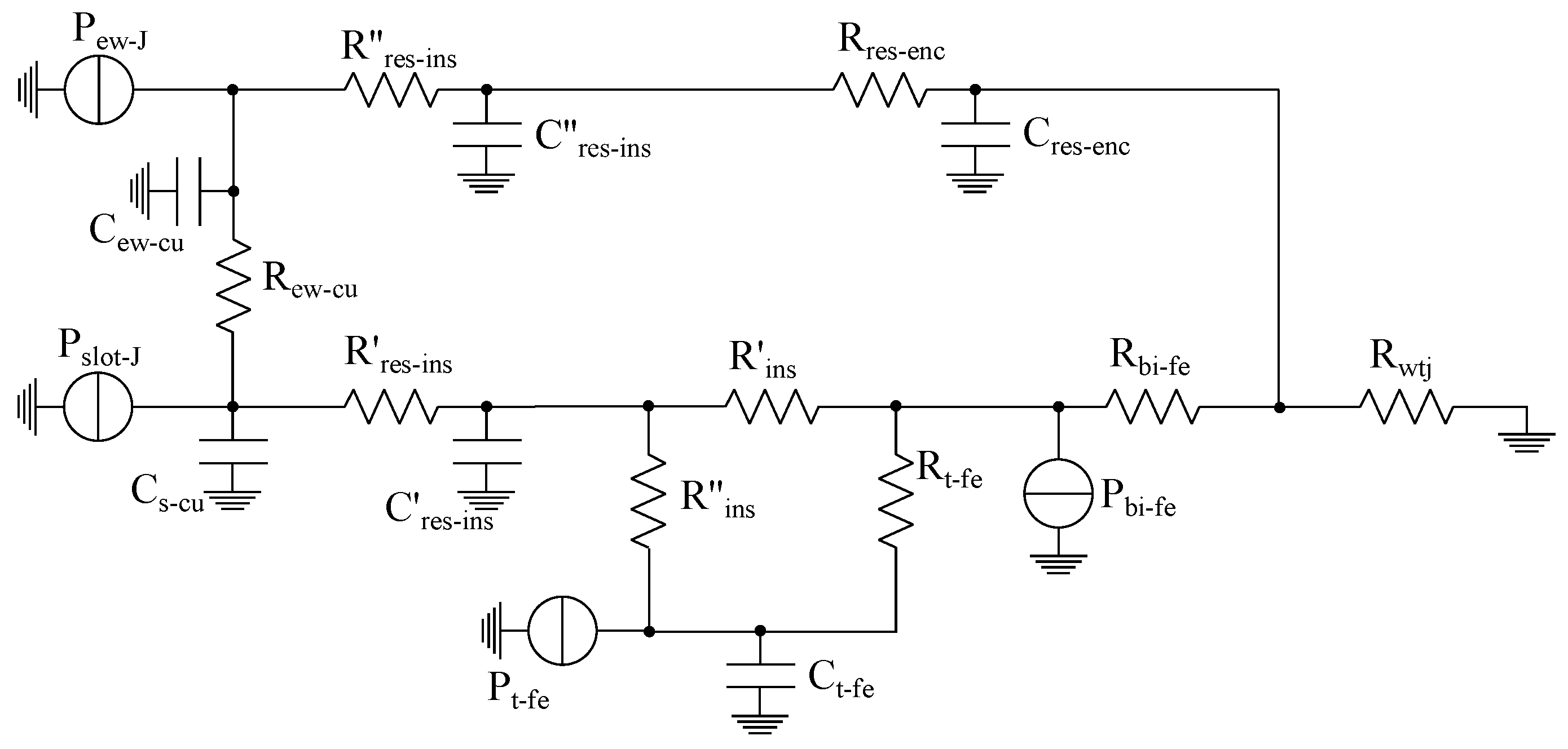
Figure 12.
Power losses of the electric motor divided into the main loss sources, reported as a function of the mechanical speed and torque.
Figure 12.
Power losses of the electric motor divided into the main loss sources, reported as a function of the mechanical speed and torque.
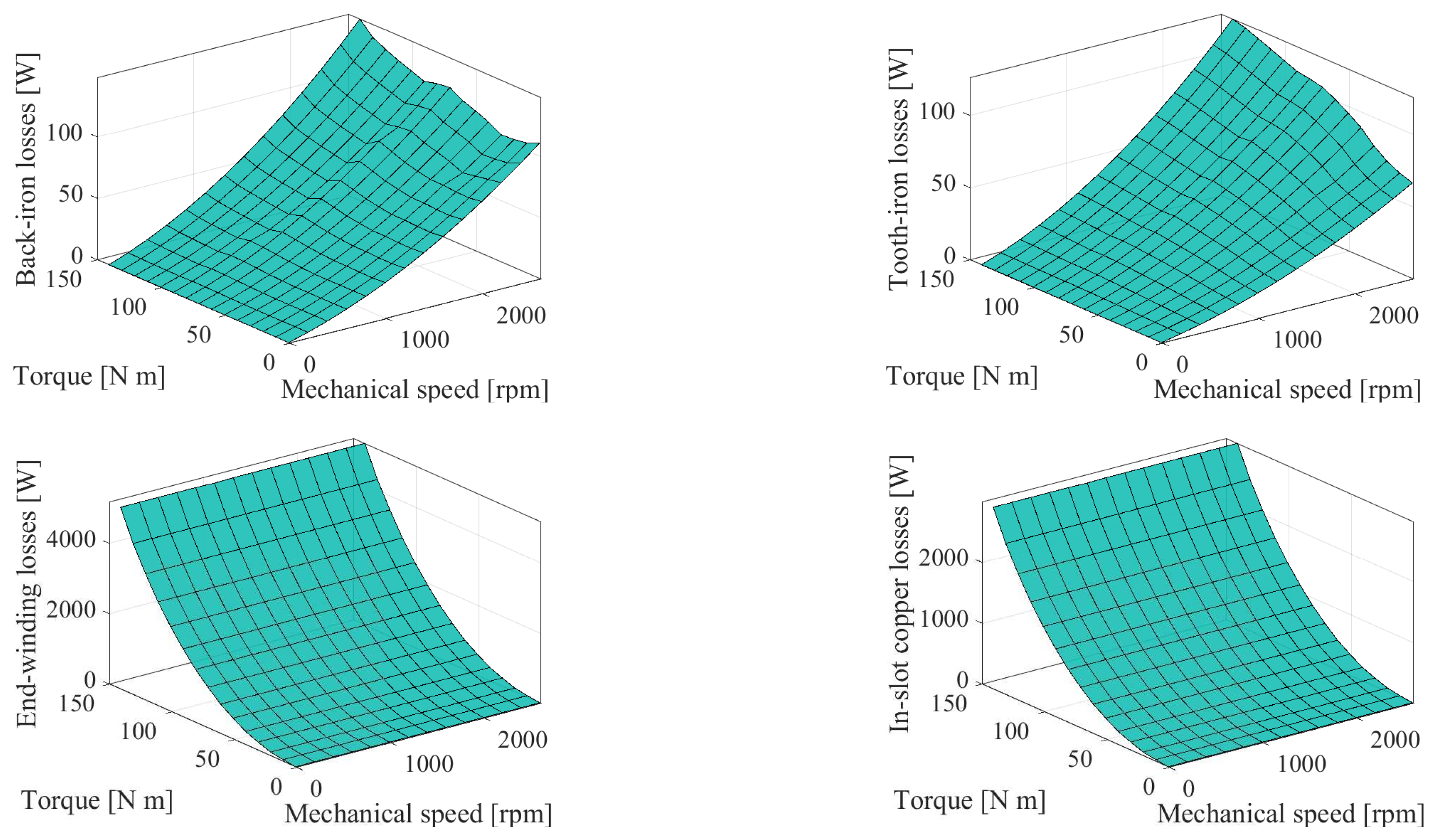
Figure 13.
Results of the thermal analysis when the electric motor is subject to a real duty cycle, showing the temperature rise in different parts of the electric motor.
Figure 13.
Results of the thermal analysis when the electric motor is subject to a real duty cycle, showing the temperature rise in different parts of the electric motor.
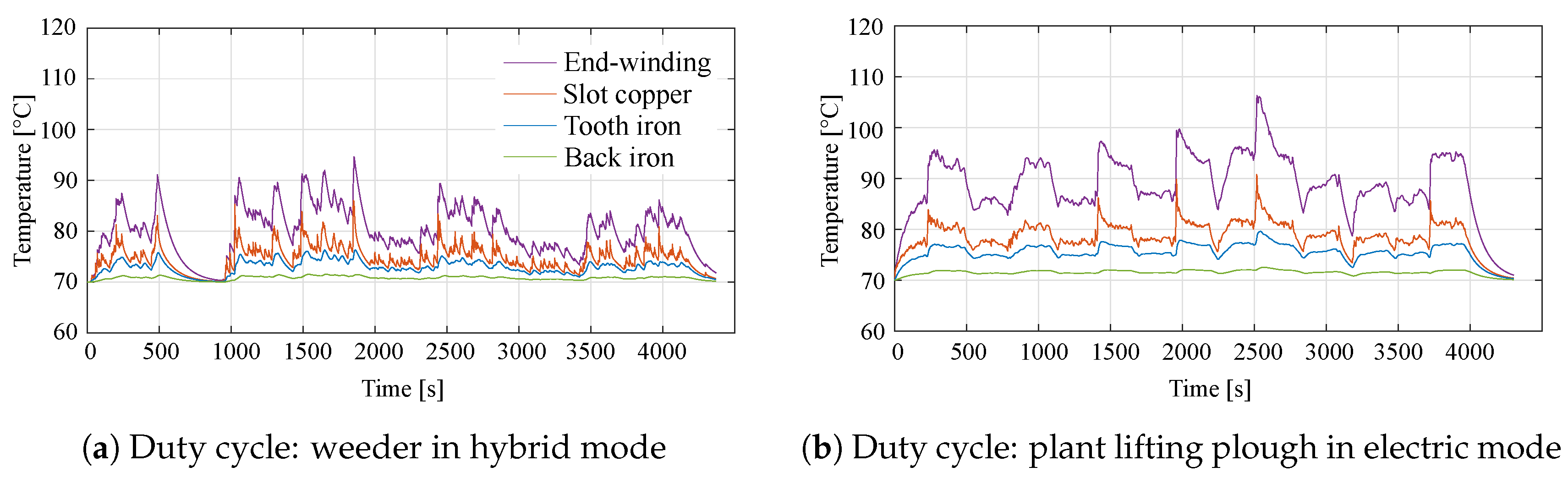
Figure 14.
Efficiency map of the designed electric motor. The dashed lines indicate the rated torque or power and rated speed limits.
Figure 14.
Efficiency map of the designed electric motor. The dashed lines indicate the rated torque or power and rated speed limits.


Table 1.
Working conditions for a specialized tractor. These are divided into groups based on the duty cycle intensity and Power Take Off PTO requirements. Traction is required for all the operations listed.
Table 1.
Working conditions for a specialized tractor. These are divided into groups based on the duty cycle intensity and Power Take Off PTO requirements. Traction is required for all the operations listed.
| Duty Cycle Intensity | PTO | Experimental Measurement |
|---|---|---|
| Heavy cultivation | Weeder; Clod breaker | |
| Medium cultivation | ✓ | Atomizer; Grape harvester; Rotary cultivator |
| Light cultivation | Plant lifting plough; Tipping machine | |
| Light cultivation | ✓ | Tying machine |
| Heavy transportation | Road trailer |
Table 2.
Electric motor geometrical data and performance.
| Parameter | Value | Unit |
|---|---|---|
| Number of slots | 36 | - |
| Number of poles | 6 | - |
| Stator outer diameter | 200 | |
| Stator inner diameter | 135 | |
| Air gap thickness | 1 | |
| Stack length | 65 | |
| Magnet thickness | 6 | |
| Stator core mass | 6.47 | |
| Rotor core mass | 3.24 | |
| Copper mass | 2.55 | |
| Magnets mass | 0.94 | |
| Lamination material | M530-50A | - |
| Winding material | Cu | - |
| PM material | NdFeB | - |
| PM remanence | 1.21 | |
| PM coercivity | 883 | / |
| Slot copper-filling factor | 0.4 | - |
| Parameter | Value | Unit |
| Rated torque | 40 | |
| Rated speed | 2600 | |
| Rated current density | 9.4 | / |
| Rated current | 24.5 | |
| Overload current | 420 | |
| Overload torque | 150 | |
| Winding peak voltage | 400 |
© 2020 by the authors. Licensee MDPI, Basel, Switzerland. This article is an open access article distributed under the terms and conditions of the Creative Commons Attribution (CC BY) license (http://creativecommons.org/licenses/by/4.0/).
Share and Cite
MDPI and ACS Style
Troncon, D.; Alberti, L. Case of Study of the Electrification of a Tractor: Electric Motor Performance Requirements and Design. Energies 2020, 13, 2197. https://doi.org/10.3390/en13092197
AMA Style
Troncon D, Alberti L. Case of Study of the Electrification of a Tractor: Electric Motor Performance Requirements and Design. Energies. 2020; 13(9):2197. https://doi.org/10.3390/en13092197
Chicago/Turabian StyleTroncon, Diego, and Luigi Alberti. 2020. "Case of Study of the Electrification of a Tractor: Electric Motor Performance Requirements and Design" Energies 13, no. 9: 2197. https://doi.org/10.3390/en13092197
Note that from the first issue of 2016, this journal uses article numbers instead of page numbers. See further details here.