Experiments and Simulation on a Late-Model Wind-Motor Hybrid Pumping Unit


1
School of Automation Science and Electrical Engineering, Beihang University, Beijing 100191, China
2
College of Mechanical Engineering, Inner Mongolia University for Nationalities, Tongliao 028000, Inner Mongolia, China
*
Author to whom correspondence should be addressed.
Energies 2020, 13(4), 994; https://doi.org/10.3390/en13040994
Submission received: 22 December 2019
/
Revised: 19 February 2020
/
Accepted: 20 February 2020
/
Published: 23 February 2020
(This article belongs to the Section A3: Wind, Wave and Tidal Energy)
Abstract
:Many oil fields are full of wind energy. At present, wind power generation technology has catered to oil fields. A larger wind turbine is used to supply power to several pumping units. As a result of the structural characteristics of the pumping unit, the efficiency of the electromotor is very low, which leads to a reduction in the utilization rate of wind energy. At the same time, considering the high cost of large wind turbines, the energy saving effect is not obvious in practical applications. This paper proposes an energy supply model of a pumping unit driven by a small wind turbine and a new wind-motor hybrid structure. Instead of wind power generation technology, wind energy drives the pumping unit directly via a mechanical–hydraulic transmission system. This new mechanical-hydraulic system can optimize the power confluence of wind and electric power. To enhance the efficiency of the motor, a mathematical model and a test station were established. The correctness of the energy conservation method and the mathematical model was verified, and the performance of the wind-motor system was studied.
1. Introduction
Petroleum is the most important traditional energy in the world; it plays an irreplaceable role in modern life and production. However, the oil extraction process consumes a lot of electrical energy, and increases production costs. The main piece of production equipment in oil fields is the beam pumping unit, which has the advantages of simple structure, high reliability, and easy maintenance. The energy consumption of the beam pumping unit accounts for 1/3 of the total energy consumption in oil fields [1]. At present, at least 100,000 beam pumping units are in use in China. The total installed capacity can be up to 3500 MW, and the power consumption is typically more than 1000 GW·h per year [2]. Therefore, it is essential to carry out research on energy saving technology for beam pumping units.
The unbalanced structure of beam pumping units leads to wild fluctuations in the load torque on the transmission shaft, and can even lead to the failure of the drive motor. In addition, during the down stroke of the pumping unit, the drive motor can be under the condition of a light load or even power generation [3], which will result in electronic energy loss or even electrical network pollution. Researchers have enhanced the structure of the beam pumping unit based on the pumping principle. Feng et al. [4] proved the effectiveness of a new structure of a heterogeneous pumping unit. Fu et al. [5] designed a new double horse-head pumping unit, and his team has verified the energy saving effect based on a simulation study. A precise system model is an important premise for operational management to save energy, reduce costs, and improve efficiency [6]. Some scientists have thoroughly studied the dynamic pumping model in order to implement energy-savings theoretically. Feng et al. [7] accurately built a mathematical model of a load motor based on dynamic changes in the pumping load; they realized that the system power matching could improve the motor’s efficiency. An energy analyzing model and 3-D dynamic model were also constructed [8,9]. Nevertheless, structural optimization can only reduce the energy loss of the drive motor, and will not solve the problem in principle.
In recent years, many researchers have devoted themselves to the study of advanced control methods. In order to avoid the motor being in the generating state, Luo et al. [10] proposed an intermittent power supply control method. The motor power cuts off when negative torque occurs, while working normally when the load torque has a positive value. This method can improve the running efficiency of the motor and achieve load matching. Zhao and Lv [11,12] studied this method to determine the interruption time of the intermittent power supply technology. It was found that load fluctuations still existed, despite the optimization of the structure and control of the pumping unit system. Therefore, from the point of view of energy regulation, Liang and Zhang [13,14] conducted a simulation of the energy regulation of a beam pumping unit based on a hydraulic system; the results showed that the hydraulic regulation scheme can reduce load fluctuations and improve the motor’s efficiency.
At present, research on energy saving technology in oil fields is mainly concerned with how to increase the efficiency of the electromotor. With the development of new energy technologies, using new energy in oil fields will be a new direction of energy saving. According to weather reports, many oil fields have abundant wind energy, which could be used instead of electrical energy to drive oil pumping units. Many oil fields in China have tried to use wind power generation instead of grid power to realize energy savings [15]. In such situationas, the oil field installs a large wind turbine to drive several pumping units. The wind power generation equipment is arranged near the pumping unit and the power supply is made available to the pumping unit simultaneously with the power grid. However, actual operation data shows that the energy saving effect is not ideal. A large-scale variable pitch wind turbine has a complex structure and high cost. The problem of the low efficiency of the motor has not been resolved, which makes the utilization of wind energy inefficient. Energy recycling and load matching have not be achieved.
Therefore, this paper proposes, for the first time, a late-model wind-motor hybrid pumping unit. This mode of wind energy utilization employs a small wind turbine drive beam pumping unit. Wind energy is not converted into electricity, but rather, uses a hydraulic transmission to directly drive the load. The new mechanical-hydraulic transmission structure can achieve a combination of wind energy and electricity, and improve motor efficiency. As power generation equipment is eliminated, the unit cost decreases and wind energy can be utilized more efficiently. This method can effectively resolve the existing problems of wind energy utilization in oil fields.
At present, there is no research on pumping units which are directly driven by wind energy. The latest hybrid transmission structure is of great significance, as it opens up new possibilities for the use of wind energy in oil fields. In addition, oil fields in remote areas face the problem of a lack of electricity, but these areas are often rich in wind resources. Large wind turbines are expensive and the cost of building a wind farm is high. The late-model wind-motor hybrid system is characterized by low cost, simple structure, and strong adaptability, making it especially suitable for oil fields in remote areas.
In this paper, a mathematical model for a wind-motor hybrid system is established. In order to research the performance of the wind-motor hybrid system, a system test station is built. By experimentation and numerical simulation, the feasibility of the wind-motor hybrid system is verified.
2. The Structure of the Wind-Motor Hybrid Pumping Unit
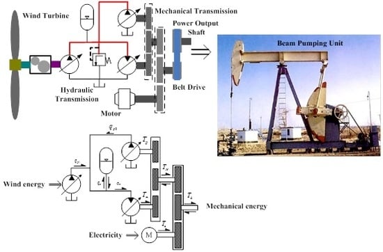
A configuration model of the current beam pumping unit is shown in the right part of Figure 1. The prime mover passes power to the crank via a pulley and reducer. The crank, linkage, rack, and beam can be regarded as four-bar linkage; the crank moves in a circle, which causes a sucker rod to move downwards. Mechanical oil recovery is realized by the reciprocating movement of the sucker rod. Generally, the beam pumping unit is driven by a high-power electric motor. However, during the up and down strokes of one oil pumping period, the value of the load torque on the crank changes greatly, leading to a lower efficiency of the motor and serious energy consumption.
The wind-motor hybrid power system is presented in the left part of Figure 1. Due to constant changes of wind speed and periodic changes of the load, it is difficult to drive the pumping unit directly from the wind turbine; therefore, wind energy must be converted into electrical energy. As the hydraulic system has the function of energy storage, the wind turbine driving the load can be realized through the hydraulic transmission. When the wind power is greater than the load power, excess energy is stored, and when the wind power is less than the load power, the electromotor starts working. The wind-motor hybrid system consists of two subsystems. One is the wind-pump system, and the other is the mechanical-hydraulic system. The wind-pump system includes a wind turbine, a speed increasing gear, and a variable pump (1). The wind turbine and pump (1) are linked through the speed-increasing gearbox. By changing the displacement of the variable pump, the speed of the wind turbine rotor can be controlled and the wind turbine can work at the optimum speed to maintain a high level of efficiency. The mechanical-hydraulic system includes a torque coupling gear, a variable pump (2), and variable hydraulic motor. The torque coupling gear can realize the power shunt and confluence. The pump and the hydraulic motor are attached by a torque coupling gear (1). The wind power output can be controlled by changing the displacement of the pump and the hydraulic motor, and excess wind energy can be stored in the accumulator. Hydraulic and electrical energy are combined by a torque coupling gear (2). Due to the serious imbalance in the mechanical structure of the pumping unit, the crank shaft produces negative torque, which makes the motor reach a state of generating electricity. This problem can be resolved by the mechanical-hydraulic system. This system can realize the recovery of gravitational potential energy and avoid the problem of the motor being in a generating state.
3. Mathematical Model of the Wind-Motor System
A mathematical model of the wind-motor hybrid system has been analyzed and demonstrated according to its working principle. Moreover, in order to simplify the research problem, it is assumed that the hydraulic pipeline should be as short as possible. Also, the compressibility of the oil should not be left out. In other words, the influence of the hydraulic pipeline and the internal volume of the pump or motor of the hydraulic system should be ignored, as should the influence of the low-pressure side pipeline pressure on the system, and the low-pressure side pipeline pressure should be regarded as zero [16,17].
3.1. Equation of the Wind Turbine
When the wind speed flowing into the wind turbine is v m/s, the wind turbine rotor captures the wind power Pw (W) as follows:
where ρ is the air density (kg·m/s2), R is the blade radius of the wind turbine rotor(m), Cp is the power coefficient of wind turbines, φ is the pitch angle, and λ is the tip speed ratio. The tip speed ratio is defined as:
where ωw is the wind turbine rotor angular velocity (rad/s).
The fixed pitch wind turbine has a simple structure and low cost, so it is suitable for the wind-motor hybrid pumping unit. The pitch angle of the fixed pitch wind turbine φ is zero. According to [18], the Cp expression of fixed pitch wind turbine may be obtained as follows:
According to Equations (2) and (3), the maximum wind-power utilization coefficient Cpmax can be obtained under the optimal tip speed ratio, λopt. At a certain wind speed, there is always an optimal wind turbine angular velocity ωwopt corresponding to λopt. The wind turbine should operate at ωwopt to capture more wind energy when the wind speed is lower than the rated wind speed.
The rotor shaft is affected by mechanical friction and viscous resistance when it revolves, and the pump is driven by the wind turbine; then, the dynamics torque equation of the wind turbine rotor shaft may be expressed as follows:
where Jw is the rotational inertia of the wind turbine rotor (kg·m2), Tw is the wind turbine blade aerodynamic torque (N·m), Tp’ is the counteractive torque of the pump (N·m), Tf is mechanical friction torque (N·m), and Bw is the viscous damping coefficient of the wind turbine rotor shaft (N·m·s/rad).
Generally, when the speed of the wind turbine is lower than that of the pump, a speed increasing gear box must be used. When the torque loss of the gearbox is ignored, the simplified model of the speed increasing gear is as follows:
where iw is the transmission ratio of the speed increasing gear box, ωp is the pump rotor angular velocity (rad/s), and Tp is the drive torque of the pump (N·m).
3.2. Equation of the Variable Displacement Pump and the Variable Displacement Hydraulic Motor
The displacement of the pump can be changed by adjusting the swash plate angle. The displacement equation is as follows:
where Dpmax is full displacement of the pump (m3/r), Dp is displacement of the pump, and βp is displacement ratio of the pump.
In consideration of the existence of mechanical friction and viscous friction inside the pump, the dynamic torque equation of the pump is as follows:
where Jp is rotational inertia of the pump rotor (kg·m2), Cpv is laminar drag coefficient of the pump, Cpf is mechanical resistance coefficient of the pump, μ is dynamic viscosity of hydraulic oil (Pa·s), np is the pump shaft rotate speed (r/s), and Ph is the pressure of the high-pressure side pipeline (Pa).
The flow equation of the pump is as follows:
where qp is the output flow of the pump (m3/s) and Cps is the laminar flow leakage coefficient.
The hydraulic motor and the pump have the same modeling process. The displacement equation of the hydraulic motor is:
where Dmmax is full the displacement of the hydraulic motor (m3/r), Dm is the displacement of the hydraulic motor, and βm is the displacement ratio of the hydraulic motor. The torque and flow equations of the hydraulic motor are as follows:
where Jm is the rotational inertia of the hydraulic motor rotor (kg·m2), ωm is the hydraulic motor rotor angular velocity (rad/s), Cmv is the laminar drag coefficient of the hydraulic motor, Cmf is the mechanical resistance coefficient of the hydraulic motor, nm is the hydraulic motor shaft rotate speed (r/s), Tm is the output torque of the hydraulic motor (N·m), qm the is the flow of the hydraulic motor (m3/s), and Cms is the laminar flow leakage coefficient of the motor.
3.3. Flow Equation of the Hydraulic Accumulator
As analyzed above, the hydraulic accumulator is used to store and reuse energy. According to Boyle’s law, the volume of an ideal gas is inversely proportional to the pressure of the gas at constant temperature; therefore, we can get:
where P0 is the inflation pressure of the accumulator (Pa), and V0 is its initial volume (m3). Since Pa is the gas pressure in the accumulator (Pa), Va is the gas volume at the condition when the gas pressure is Pa (m3). r is gas polytropic coefficient. What is more, the isothermal coefficient is 1.0, and the adiabatic coefficient is 1.4. Then, by taking the derivative with respect to time, we can obtain the equation as follows:
Given that the inlet and outlet flow of the accumulator is equal to the change in the volume of the internal gas, the flow qa (m3/s) of the accumulator is defined as follows:
To simplify the problem, the influence of the interface pipeline on the accumulator is not considered. When the gas in the accumulator is compressed, its internal gas pressure Pa is equal to the external pipeline pressure Ph.
3.4. System Torque Equation and Flow Equation
Torque coupling means that the output torque of the shafts is independent, and the rotational speed of the shafts is equal. The relationships of the rotational speed and the torque are as follows:
where n1, n2, n3, and n4 are the rotational speeds of the shafts, and T1, T2, T3, and T4 are the torques.
According to Figure 1, the total transmission ratio of the reducer and the belt pulley is i. The crank speed of the pumping unit is nL, the load torque of the crank shaft is TL, the electromotor speed is expressed as ne, and the electromotor output torque is Te. According to Figure 2, the pump and the hydraulic motor have the same rotating speed, which is different from that of the motor. The transmission ratio of the torque coupling gear groups is i1. When the torque losses of the gears are ignored, the speed and torque relationship between the pump, the hydraulic motor, and the electromotor are as follows:
According to the mechanical-hydraulic system, the flow equation of the system is expressed as follows:
where qp1 and qp2 are the flows of pump (1) and pump (2), respectively.
3.5. System Efficiency Equations
In order to realize the maximum capture of wind energy, the wind turbine rotor is often accelerated or slowed in practical situations. The wind turbine is a great inertia system; it continuously stores and releases energy during its variable-speed operation. Thus, the main energy loss of the wind turbine results from mechanical and viscous friction, although this loss is usually small in reality. Therefore, this paper studies the effect of the efficiency parameters when the wind turbine works at a constant rotation speed and power, the friction loss is ignored, and the following equation is true.
The efficiency equation of the wind-pump system is defined as follows:
where ηw-p is the efficiency of the wind-pump system and Pw-p is output power.
From the characteristics of the wind turbine, different wind speeds correspond to different optimal rotation speeds and wind power. According to Equations (7) and (8), the efficiency Equation (21) can be expressed as follows:
The system works outdoors and has good heat dissipation. The properties of oil are approximately unchanged. The wind-pump system efficiency will change with wind power, pump speed, and working pressure. When the wind speed is lower than the rated wind speed, the wind turbine should operate at the optimum speed. According to Equations (1), (2), (3), and (5), the relationship between np and pw is shown as follows:
In addition, the speed of the pump should not exceed its maximum value, otherwise the pump will be damaged. When the wind speed is greater than the rated wind speed, the wind turbine should operate at a constant speed. Therefore, the efficiency of the system only depends on the pressure and wind power. The loss of power in the mechanical-hydraulic system is mainly due to the pump and hydraulic motor when the pipeline losses are not considered. The efficiency model of the mechanical-hydraulic system is defined as follows:
where Pe is the output power of the electromotor, Pp-loss is the power loss of pump, and Pm-loss is the power loss of hydraulic motor. The inertia torque loss of the system is not considered. Pp-loss and Pm-loss are obtained as follows:
Many parameters affect the efficiency of the mechanical-hydraulic system. The best combination of parameters can improve system performance. When the electromotor, pump, and hydraulic motor are unchanged, the system efficiency is mainly affected by Ph, np, nm, Pw-p, and Pe.
4. Experimental System of the Wind-Motor Hybrid System
4.1. Experiment Setup
As shown in Figure 2, a test station was built to verify the designed hybrid system and the mathematical model. According to the principle of the wind-motor hybrid system, three groups of gear couplings were adopted. Three torque and speed sensors were employed. The wind turbine rotor was simulated by a DC motor (1) and an inertia disc. The output torque of the DC motor (1) comprised a closed-loop controlled by the feedback of the torque sensor (1). The pump (1) was driven by a DC motor (1) to simulate the wind-pump system.
This paper simulates the real physical working process of the pumping unit according to the load torque on the crank. The actual physical system includes positive and negative torque. In order to simulate the beam pumping unit, a magnetic powder clutch and brake were designed. The magnetic powder brake can simulate positive torque, while negative torque was simulated using a DC motor (2) and a magnetic powder clutch.
The work process of the beam pumping unit was simulated by close-loop controlling torque of the feedback of the torque sensor (3). A torque sensor (2) was adopted to measure the output torque of the electromotor. Figure 3 shows the test station of the wind-motor hybrid system. According to experience, vibration and noise occur when the quality of the transmission parts is not high. The component parameters of the main devices used in this experiment are shown in Table 1.
4.2. Numerical Simulation Model
This paper uses AMEsim-Matlab united simulation. The beam pumping unit model was established using the AMEsim software. The program of the AMEsim software is shown in Figure 4. The wind-pump system model and mechanical-hydraulic system model were established using the Matlab software; the specific structure is shown in Figure 5. The wind-pump system model included wind speed, the wind turbine, the pump, and the speed increasing gear. The mechanical-hydraulic system model included the pump, hydraulic motor, and accumulator. The system adopted an axial piston pump and motor as the main hydraulic components. In order to simplify the problem, the clearance change of the pump and hydraulic motor was ignored during operation. The loss coefficient under full displacement was used as the simulation value to meet the research needs according to the operating conditions and upon consulting with the manufacturers. The simulation parameters of the hydraulic system are shown in Table 2.
5. Results and Discussion
5.1. Experiments on Load Simulation
This study takes the beam pumping unit model CYJ10-3-37HB as its research object. This type of pumping unit adopts the crank load balance method. The manufacturer provided some technical data on the unit. The load curve is fitted by reducing the measured data of the oil well in equal proportion, and done in the experiment. Due to the short experiment time, the influence of temperature was ignored. At the same time, in the actual application of the system, temperature can be regarded as a constant.
The motor experimental curve and the load fitting curve were as shown in Figure 6. When the wind-pump and the mechanical-hydraulic system were not connected to the motor, the output torque of the motor varied with the load. The amplitude range of the load curve was from about −3 to 23 N·m, and part of the curve crossed the zero line, leading to the low efficiency of the motor. The experimental curve of the motor was consistent with the load fitting curve, which verified the effectiveness of the experimental system. The experimental results show that the load torque on the crank of pumping unit was well simulated using the magnetic powder clutch and brake.
According to the load fitting curve, the wind turbine rotor blade radius was determined to be 0.8 m, the maximum wind-power utilization coefficient Cpmax was 0.45, and the optimal tip speed ratio λopt was set to 9.5. Using Equations (1), (2), (3) and (4), wind power and optimal speed can be obtained. The speed and torque of the wind turbine was simulated using a DC motor and an inertia disc. The full displacement of the pump connected to the DC motor was 25 cc/r, and the DC motor was used to simulate the wind turbine. The hydraulic system experimental pressure was set to 6 MPa and the rotation speed of the gear coupling was set to 730 r/min. In the mechanical-hydraulic system, the full displacement of pump and the full displacement of hydraulic motor were 25 cc/r and 28 cc/r, respectively. As shown in Figure 7, the output torque of the mechanical-hydraulic system can be changed with the load by dynamically adjusting the displacement of the pump and hydraulic motor. This suggests that the electromotor output torque and power remain stable, and the mechanical-hydraulic system achieves hybrid power and energy distribution.
5.2. Experiments on Hybrid Power
Wind turbine rotor simulation experiments were carried out at different wind speeds, i.e., 9, 10, and 11 m/s. The experimental results are shown in Figure 8. The experiment verified the hybrid power process at different wind speeds. The motor power could be stabilized by changing the displacement of the pump and hydraulic motor, and the mechanical-hydraulic system output power followed the load. This helps to improve the efficiency of the motor. When the wind speed was 9 m/s, the output power of the electromotor was around 580 W; an increase of wind power led to a decrease of electric power. When the wind speed was 11 m/s and the wind power was 740 W, the electric power was around 300 W. The simulation and experimental results show that the stable range of the motor output power was different when the wind power was different.
The simulation and experiment results are consistent with each other under different wind speeds. The correctness of the mathematical model and energy saving method was verified by simulation and experiment. The experiments showed that the wind-motor hybrid system could realize power mixing and energy regulation, and that the wind could drive the load directly through the hydraulic transmission system without electrical energy conversion. The effectiveness and novelty of this new method of wind energy utilization have been demonstrated by experiments.
In order to achieve stable electromotor power, the hydraulic system must constantly store and release energy when the load torque fluctuation changes, so the pipeline pressure fluctuation changes to around 6 MPa. Figure 9 is the pressure dynamic change curve of the hydraulic system. It may be seen that the pressure change was the same when the experiment was carried out at different experimental wind speeds. This suggests that the sum of the wind-pump system output power Pw-p and the electromotor power Pe met the requirements of the load power, and that the hydraulic systems neither store nor release any excess energy. In this case, the pressure change must be the same when the wind speed is different.
5.3. Experiments on the Efficiency of the Wind-Pump System
According to Equation (21) and the experimental data, the wind-pump efficiency dynamic change curves were determined, as shown in Figure 10. Different wind speeds correspond to different optimal speeds and aerodynamic torques. Through closed-loop feedback control of the DC motor of the simulation system, the wind turbine rotor under different working conditions was simulated and the speed and torque were kept constant. From Figure 9 and Figure 10, it can be seen that the wind-pump efficiency reduces when the hydraulic system pressure rises. As the system pressure drops, the wind-pump efficiency increases. As calculated using Equation (7), when the wind speed is not changed, a change in the pipeline pressure will cause a change in the displacement in the pump. When the pressure increases, the displacement of the pump decreases, and a small displacement occurs, the efficiency of the pump is lower.
Figure 11 is an efficiency comparison curve at different experimental wind speeds. The wind-pump system average efficiency of 11 m/s wind speed is greater than 9 m/s and 10 m/s. This is because the aerodynamic torque value of 11 m/s is relatively larger, and the variable pump will operate at a greater displacement. Thus, the wind-pump system average efficiency is greater. The experimental results indicate that the system’s efficiency will increase with an increase in wind speed. Equations (22) and (23) show that pressure and wind power influence the system efficiency; this conclusion was verified by the experiment.
5.4. Experiments on the Efficiency of the Mechanical-Hydraulic System
From Equations (24), (25), and (26), we see that the mechanical-hydraulic system efficiency is mainly affected by Ph, np, nm, Pw-p, and Pe. The speed of the pump, the hydraulic motor, and the electromotor is satisfied with Equation (17). The experimental coupling speed is 730 r/min. The mechanical-hydraulic system efficiency dynamic change experimental curves were obtained and are shown in Figure 12. According to the experimental conditions of the test station, the displacement of the pump and the hydraulic motor did not change, the rotational speed was constant, and the load torque was the same. At this point, the main factor affecting the efficiency of the system was pressure. According to Figure 9, pressure change was the same when the sum of wind-pump system output power and the electromotor power met the load requirements. Therefore, the efficiency experimental curves were very close, and their changes followed the pressure.
A comparison of the efficiency of the mechanical-hydraulic system at different wind speeds is presented in Figure 13. As shown, the average value of system efficiency is the same at different wind speeds; in other words, regardless of wind speed changes, the average efficiency does not change under the same operating conditions as long as the hydraulic system does not store energy.
5.4.1. The Effect of Pressure on Efficiency
As shown in Figure 12, a change of pressure causes a change in the efficiency of the mechanical-hydraulic system. The mechanical-hydraulic system’s efficiency change is the same as under different wind speeds, so long as Pw-p and Pe meet the requirements of load power. Therefore, the experiment may be simplified as follows: only the motor drives the load, while other system parameters remain unchanged. The experiment was carried out at 10.0 MPa.
As shown in Figure 14, a motor torque of 10.0 MPa is greater than 6.0 MPa. This suggests that when the load power is unchanged, the mechanical-hydraulic system loses more energy under 10 MPa. A hybrid system efficiency of 10.0 MPa is less than 6.0 MPa. According to the energy regulation principle, the hydraulic system always stores and releases the same amount of energy under different working pressures. When the full displacement values of pump and hydraulic motor are determined and their speed is constant, the hydraulic system will store a greater volume of liquid under lower pressure. At this moment, the pump and hydraulic motor should work under large displacement, and their loss of energy is smaller. The mechanical-hydraulic system has greater efficiency under lower pressures. Therefore, different full displacements of the pump and hydraulic motor correspond to the appropriate pressure, in order to make the system more efficient.
5.4.2. The Effect of the Coupling Speed on Efficiency
According to the efficiency equation, the coupling speed affects the efficiency of the mechanical-hydraulic system. The authors carried out simulation and experimental research at different pump and hydraulic motor speeds. The load power was the same when the experiment speed was set to 730 r/min and 460 r/min. Simulation and experimental dynamic comparison curves are shown in Figure 15. A motor output power of 460 r/min is less than 730 r/min, which suggests that the system’s efficiency is affected by the rotation speed. Reasonable speed determination can improve efficiency.
5.5. Analysis of the Effect of Mechanical-Hydraulic System Parameters on Efficiency
From Equations (25) and (26), the influence of the full displacement value of the pump and hydraulic motor on the efficiency of the mechanical-hydraulic system may be calculated. Due to the limitations of the experimental conditions, this was not studied. However, the mechanical-hydraulic system efficiency is greatly affected when the pressure and coupling rotation speed of the pump and hydraulic motor are different under different full displacement values. According to the usage requirements and torque coupling principle, the full displacement of the pump and hydraulic motor should meet the conditions laid out in the following equations:
where TLmax and TLmin are the maximum and minimum torque of the crank shaft, TL is the average of the crank shaft, and βpmin and βmmin are the minimum displacement ratios of the pump and hydraulic motor, respectively. ph is the average working pressure.
Equations (27) and (28) represent the relationship between the system parameters. The pumping unit system parameters include the rotation speed of the motor ne, the total transmission ratio i, and the torque of the crank shaft. When the pumping system parameters are unchanged, the full displacement of the pump and hydraulic motor can be obtained using Equations (27) and (28). Therefore, the system efficiency is determined by the average pressure, coupling speed, minimum displacement ratio, and system input power. This paper uses the parameters of the CYJ10-3-37HB pumping unit and a simulation model to study the mechanical-hydraulic system. Depending on the actual data of the oilfield, the average output power of the motor is only 6 kW.
5.5.1. Input Power of the System
The system input power includes wind-pump system output power Pw-p and electric power Pe. Depending on the experimental results shown in Figure 13, in the process of power mixing, the system input energy meets the load demand, and the system efficiency remains unchanged. To further verify this conclusion, Pw-p was set to 0, 2, 4, and 6 kW, the working average pressure was set to 10 MPa, and the coupling speed was set to 730 r/min. The influence of parameter Pw-p on the efficiency of the mechanical-hydraulic system is shown in Figure 16.
As shown in Figure 16, the output power of the wind-pump system varies from 0 to 6 kW. When power Pw-p increases, the average efficiency increases and the motor power decreases. This is because the range of displacement regulation has changed, but the change is very small. So, the influence of the output power of the wind-pump system on the efficiency of the mechanical-hydraulic system is very slight. It can therefore be considered that the efficiency does not vary with variations in wind power. To facilitate discussion of this problem, the wind-pump system’s output power can be regarded as zero. Once again, the simulation results are in agreement with the experimental results.
5.5.2. Minimum Displacement Ratio
From Equations (27) and (28), when other parameters are determined, the full displacement of the pump and hydraulic motor is determined by the minimum displacement ratio. Parameters βpmin and βmmin influence the efficiency of the mechanical-hydraulic system. The working average pressure was set to 10 MPa, the coupling speed was set to 730 r/min, βmmin was set to 1, and βpmin was set to 0.1–0.5. The influence curve is shown in Figure 17.
As shown in Figure 17, the minimum displacement ratio of the pump has a great influence on efficiency. As the minimum displacement ratio increases, the efficiency decreases. A larger minimum displacement ratio can obtain greater full displacement, and the power loss will increase. Accordingly, βpmin should be set to a small value. When βpmin is set to 1 and βmmin is set to 0.1–0.5, the same conclusion is obtained.
5.5.3. Pressure and Coupling Speed
The experimental results show that the working pressure and coupling rotation speed influence the system efficiency. The minimum displacement ratio was set to 0.2, and the output power of the wind-pump system was set to zero. Figure 18 shows the combined efficiency curves coupling rotation speed and system pressure. The efficiency change trend is different under different combinations of parameter. It can be seen that there is a coupling relationship between the coupling rotation speed and the system pressure. These two parameters have a great effect on efficiency. The maximum efficiency can be obtained under the optimal parameters. Therefore, when designing the working speed and pressure of the hybrid power system, the relationship between these variables should be considered; maximum efficiency and minimum energy loss can be achieved with an optimal relationship.
Because the speed of the crank of the pumping unit is very low, the coupling speed should be reduced as much as possible to ensure efficiency. This will reduce the gearbox size and cost. High pressure and high speed mean high costs. Therefore, the working pressure range should be 10–15 MPa. When these two parameters are determined, the pump and motor displacement is also determined.
6. Conclusions
This paper presents a new method of utilizing wind energy in oil fields. The power transmission structure of the late-model wind-motor hybrid pumping unit can realize hybrid power, energy distribution, and recycle the gravitational potential energy of the pumping system. The effectiveness of the hybrid power system, through numerical simulations and experiments, was verified. Therefore, a single pumping unit can be driven by a small wind turbine using the latest hybrid power system. This novel method can reduce the cost of wind turbines and improve motor efficiency.
This paper studied the performance of the wind-pump and mechanical-hydraulic systems. The conclusions are as follows:
- The efficiency of the wind-pump system increases with an increase of wind speed, which means that the system efficiency is lower under low wind speeds. Pipeline pressure affects the wind-pump system efficiency, i.e., efficiency will decline when pressure increases.
- When the output power sum of the wind-pump system and the electromotor meets the load requirements, the pipeline pressure change is the same and the efficiency of the mechanical-hydraulic system changes according to the pressure. Additionally, the system efficiency is low when the experiments are under high pressure. Therefore, the pipeline pressure is a fundamental parameter of the hybrid power system, which affects the efficiency of the wind-pump and mechanical-hydraulic systems. The effect of rotating the speed of the pump and hydraulic motor on system efficiency was checked by experiments.
- Many parameters that affect efficiency; this paper studies the sensitivity of these parameters in a mechanical-hydraulic system. The influence of the output power of the wind-pump system on the efficiency of the mechanical-hydraulic system is very slight, and the simulation results are the same as the experimental results. A minimum displacement ratio, working pressure, and coupling rotation speed have a great effect on efficiency. The minimum displacement ratio should be set to a small value. The working pressure should be between 10–15 MPa, and the best coupling rotation speed is 730 r/min when cost is considered.
Author Contributions
L.W. completed project management and provided fund support; C.Z. completed simulation, experiment and writing; H.L. completed programming and data processing. All authors have read and agreed to the published version of the manuscript.
Funding
This research was funded by “The National Nature Science Foundation of china, grant number 51865046”, “Science and technology innovation leading project of Inner Mongolia, grant number KCBJ2018028” and “Program for Young Talents of Science and Technology in Universities of Inner Mongolia Autonomous Region, grant number NJYT-19-B15”.
Conflicts of Interest
The authors declare no conflict of interest.
References
- Li, K.; Han, Y.; Wang, T. A novel prediction method for down-hole working conditions of the beam pumping unit based on 8-directions chain codes and online sequential extreme learning machine. J. Pet. Sci. Eng. 2018, 160, 285–301. [Google Scholar] [CrossRef]
- Lu, J.M.; He, J.P.; Mao, C.X. Design and implementation of a dual PWM frequency converter used in beam pumping unit for energy saving. IEEE Trans. Ind. Appl. 2014, 50, 2948–2956. [Google Scholar] [CrossRef]
- Luo, W.; Wang, B.; Zhao, H.S. Modeling and simulation of non-linear dynamic process of the induction motor system with fluctuating potential loads. Sci. China Technol. Sci. 2014, 57, 1729–1737. [Google Scholar] [CrossRef]
- Feng, Z.M.; Fang, X.; Ding, H.H. Study on working performance of phased beam pumping unit. J. Balk. Tribol. Assoc. 2016, 22, 104–111. [Google Scholar]
- Fu, H.L.; Zou, L.Q.; Wang, Y.; Feng, Z.P.; Song, Z.H. Study on design and simulation analysis of the double horse-head pumping unit based on the compound balance structure. J. Mech. Eng. Sci. 2015, 229, 3034–3046. [Google Scholar] [CrossRef]
- Li, K.; Han, Y. Modelling for motor load torque with dynamic load changes of beam pumping units based on a serial hybrid model. Trans. Inst. Meas. Control 2018, 40, 903–917. [Google Scholar] [CrossRef]
- Feng, Z.M.; Tan, J.J.; Liu, X.L.; Fang, X. Selection method modelling and matching rule for rated power of prime motor used by beam pumping units. J. Pet. Sci. Eng. 2017, 153, 197–202. [Google Scholar] [CrossRef]
- Zhao, H.S.; Wang, Y.L.; Zhan, Y. Practical model for energy consumption analysis of beam pumping motor systems and its energy saving applications. IEEE Trans. Ind. Appl. 2017, 54, 1006–1016. [Google Scholar] [CrossRef]
- Feng, Z.M.; Tan, J.J.; Sun, Y.N. 3D-Dynamic Modelling and Performance Analysis of Service Behavior for Beam Pumping Unit. Math. Probl. Eng. 2018, 2018, 9205251. [Google Scholar]
- Luo, Y.L.; Cui, X.H.; Zhao, H.S. A multifunction energy-saving device with a novel power-off control strategy for beam pumping motors. IEEE Trans. Ind. Appl. 2011, 47, 1605–1611. [Google Scholar]
- Zhao, H.S.; Wang, Y.L.; Chen, G.; Zhan, Y.; Xu, G.R. Precise Determination of Power-Off Time of Intermittent Supply Technology Based on Fuzzy Control for Energy Saving of Beam Pumping Motor Systems. Electr. Power Compon. Syst. 2018, 46, 197–207. [Google Scholar] [CrossRef]
- Lv, H.Q.; Liu, J.; Han, J.Q.; Jiang, A. An energy saving system for a beam pumping unit. Sensors 2016, 16, 685. [Google Scholar] [CrossRef] [PubMed] [Green Version]
- Liang, Y.J.; Wang, T.J.; Wang, X.; Liang, W.Q.; Liu, X.H. Simulation research on hydraulic hybrid assistant beam pumping unit. Proc. Inst. Mech. Eng. Part C J. Mech. Eng. Sci. 2016, 230, 1795–1804. [Google Scholar] [CrossRef]
- Zhang, C.Y.; Wang, L.H. Simulation research on hydraulic energy regulation system of beam pumping unit. In Proceedings of the IEEE ICMA 2019, Tianjin, China, 4–7 August 2019. [Google Scholar]
- Wang, L.H. Research on Energy Saving Principle of Pumping Unit Driven by Wind Turbine. In Proceedings of the IEEE ICMA 2019, Tianjin, China, 4–7 August 2019. [Google Scholar]
- Liu, Y.G.; Gao, X.H.; Pei, Z.C. Research of Impact Load in Large Electrohydraulic Load Simulator. Math. Probl. Eng. 2014, 2014, 821419. [Google Scholar] [CrossRef] [Green Version]
- Liu, Y.G.; Gao, X.H.; Yang, X.W. Research of Control Strategy in the Large Electric Cylinder Position Servo System. Math. Probl. Eng. 2015, 2015, 167628. [Google Scholar] [CrossRef] [Green Version]
- Soufi, Y.; Kahla, S.; Bechouat, M. Feedback linearization control based particle swarm optimization for maximum power point tracking of wind turbine equipped by PMSG connected to the grid. Int. J. Hydrogen Energy 2016, 41, 20950–20955. [Google Scholar] [CrossRef]
Figure 1.
Configuration model of the hydraulic-motor hybrid beam pumping unit. 1. Wind turbine; 2. speed increasing gear; 3. variable pump (1); 4. accumulator; 5. relief; 6. variable pump (2); 7. hydraulic motor; 8. torque coupling gear (1); 9. torque coupling gear (2); 10. electromotor; 11. small pulley; 12. belt; 13. large pulley; 14. reducer; 15. crank; 16. linkage; 17. Balance weight; 18. beam; 19. horsehad; 20. sucker rod.

Figure 2.
Sketch diagram of the test station. 1. DC motor (1); 2. torque and speed sensor (1); 3. inertia disc; 4. variable displacement pump (1); 5. flow sensor; 6. accumulator; 7. pressure sensor; 8. overflow valve; 9. variable displacement motor; 10. torque coupling gear group (1); 11. variable displacement pump (2); 12. AC motor; 13. torque and speed sensor (2); 14. torque coupling gear group (2); 15. torque and speed sensor (3); 16. torque coupling gear group (3); 17. magnetic powder brake; 18. magnetic powder clutch; and 19. DC motor (2).

Figure 3.
Test station of the wind-motor system.

Figure 4.
Beam pumping unit model. 1. Simulink-AMESim interface model; 2. reducer model; 3. four-link mechanism model; and 4. polished rod load.
Figure 4.
Beam pumping unit model. 1. Simulink-AMESim interface model; 2. reducer model; 3. four-link mechanism model; and 4. polished rod load.

Figure 5.
Wind-motor hybrid power pumping unit model.

Figure 6.
Load fitting curve and motor torque experimental curve.

Figure 7.
Mechanical-hydraulic system output torque dynamic change curve when wind speed is 9 m/s.

Figure 8.
Simulation and experimental comparison curve under different wind speeds. (a,b) Wind speed is 9 m/s; (c,d) wind speed is 10 m/s; and (e,f) wind speed is 11 m/s.
Figure 8.
Simulation and experimental comparison curve under different wind speeds. (a,b) Wind speed is 9 m/s; (c,d) wind speed is 10 m/s; and (e,f) wind speed is 11 m/s.

Figure 9.
The pressure dynamic change curve of the hydraulic system.

Figure 10.
Efficiency experiment contrast curve of the wind-pump system under different wind speeds.
Figure 10.
Efficiency experiment contrast curve of the wind-pump system under different wind speeds.

Figure 11.
Efficiency of the wind-pump system comparison at different wind speeds.

Figure 12.
Efficiency experiments contrast curve of the mechanical-hydraulic system under different wind speeds.
Figure 12.
Efficiency experiments contrast curve of the mechanical-hydraulic system under different wind speeds.

Figure 13.
Efficiency of the mechanical-hydraulic system comparison at different wind speeds.

Figure 14.
The output torque experiment contrast curves of the electromotor under different pressures. (a) 6.0 MPa; (b) 10.0 MPa.
Figure 14.
The output torque experiment contrast curves of the electromotor under different pressures. (a) 6.0 MPa; (b) 10.0 MPa.

Figure 15.
The output power experiment contrast curves of the electromotor under different coupling speeds. (a) Coupling speed of 730 r/min; (b) coupling speed of 460 r/min.
Figure 15.
The output power experiment contrast curves of the electromotor under different coupling speeds. (a) Coupling speed of 730 r/min; (b) coupling speed of 460 r/min.

Figure 16.
The influence of parameter Pw-p on the efficiency of the mechanical-hydraulic system.

Figure 17.
The influence of parameter βpmin on the efficiency of the mechanical-hydraulic system.

Figure 18.
The influence trend of pressure and coupling rotation speed on the efficiency of the mechanical-hydraulic system.
Figure 18.
The influence trend of pressure and coupling rotation speed on the efficiency of the mechanical-hydraulic system.


Table 1.
Parameters of the experimental main components.
| Components | Type | Parameters |
|---|---|---|
| Axial piston variable pump | BCY14-1B-25 | Full displacement: 25 cc/r Nominal pressure: 31 MPa Rated speed: 3000 rpm |
| Axial piston variable motor | A6VM28EP12FZ | Full displacement: 28 cc/r Nominal pressure: 35 MPa Rated speed: 4700 rpm |
| Three-phase asynchronous motor | YVF100L | Rated power: 2.2 kW Rated speed: 1450 rpm |
| Magnetic powder brake | FZ25J | Rated torque: 5 N·m Maximum speed: 1500 r/min Power supply voltage: 24 V Power supply current: 0.5 A |
| Magnetic powder clutch | FL6J | Rated torque: 6 N·m Maximum speed: 1500 r/min Power supply voltage: 24 V Power supply current: 0.9 A |
| Dc motor | 80BL180S120 | Nominal power: 1.2 kW |
| Dc motor | 80BL110S50 | Nominal power: 500 W |
| Accumulator | NXQA6.3L | Volume: 6.3 L |
| Torque sensor | JN-DN28 | Range of the input signal: 1–5 V Range of the detect torque: 0–30 N·m |
| Flow sensor | DN10-50 | Power supply voltage: 24 V Output current: 4–20 mA |
| Press sensor | SIN-P300 | Power supply voltage: 24 V Output current: 4–20 mA |
Table 2.
Parameters of the simulation of the hydraulic system.
| Parameter | Value | Parameter | Value |
|---|---|---|---|
| Cps | 0.8 × 10⁻⁹ | Cms | 1.6 × 10⁻⁹ |
| Cpv | 2 × 10⁵ | Cmv | 1.25 × 10⁵ |
| Cpf | 0.01 | Cmf | 0.01 |
| μ | 0.051 Pa·s | V0 | 5 L |
© 2020 by the authors. Licensee MDPI, Basel, Switzerland. This article is an open access article distributed under the terms and conditions of the Creative Commons Attribution (CC BY) license (http://creativecommons.org/licenses/by/4.0/).
Share and Cite
MDPI and ACS Style
Zhang, C.; Wang, L.; Li, H. Experiments and Simulation on a Late-Model Wind-Motor Hybrid Pumping Unit. Energies 2020, 13, 994. https://doi.org/10.3390/en13040994
AMA Style
Zhang C, Wang L, Li H. Experiments and Simulation on a Late-Model Wind-Motor Hybrid Pumping Unit. Energies. 2020; 13(4):994. https://doi.org/10.3390/en13040994
Chicago/Turabian StyleZhang, Chunyou, Liang Wang, and Hong Li. 2020. "Experiments and Simulation on a Late-Model Wind-Motor Hybrid Pumping Unit" Energies 13, no. 4: 994. https://doi.org/10.3390/en13040994
Note that from the first issue of 2016, this journal uses article numbers instead of page numbers. See further details here.