Magnetic Field Characteristics and Stator Core Losses of High-Speed Permanent Magnet Synchronous Motors
by
Dajun Tao
1,2,*, 
Kai Liang Zhou
1,
Fei Lv
1,
Qingpeng Dou
1,
Jianxiao Wu
1,2,
Yutian Sun
1 and
Jibin Zou
3 1
Harbin Electric Machinery Company Limited, Harbin 150040, Heilongjiang Province, China
2
National Engineering Research Center of Large Electric Machines and Heat Transfer Technology, Harbin University of Science and Technology, Harbin 150080, Heilongjiang Province, China
3
Harbin Institute of Technology, Harbin 150001, Heilongjiang Province, China
*
Author to whom correspondence should be addressed.
Energies 2020, 13(3), 535; https://doi.org/10.3390/en13030535
Submission received: 4 January 2020
/
Revised: 17 January 2020
/
Accepted: 20 January 2020
/
Published: 22 January 2020
(This article belongs to the Special Issue Advances in Rotating Electric Machines)
Abstract
:This study focuses on the core losses in the stator region of high-speed permanent magnet synchronous motors, magnetic field characteristics in the load region, and variations in iron losses caused by changes in these areas. A two-pole 120 kW high-speed permanent magnet synchronous motor is used as the object of study, and a two-dimensional transient electromagnetic field-variable load circuit combined calculation model is established. Based on electromagnetic field theory, the electromagnetic field of the high-speed permanent magnet synchronous motor under multi-load conditions is calculated using the time-stepping finite element method. The magnetic field distribution of the high-speed permanent magnet synchronous motor under a multi-load condition is obtained, and the variations in iron core losses in different parts of the motor under multi-load conditions are further analyzed. The calculation results show that most of the stator iron core losses are dissipated in the stator yoke. The stator yoke iron loss under the no-load condition exceeds 70% of the total stator iron core loss. The stator yoke iron loss under rated operation conditions exceeds 50% of the total stator iron core loss. The stator loss under rated load operation conditions is higher than that under no-load operation. These observations are sufficient to demonstrate that the running status of high-speed motors is closely related to the stator iron losses, which have significance in determining the reasonable yoke structure of high-speed and high-power motors and the cooling methods of motor stators.
1. Introduction
With the increasing market demand for high-efficiency motors for driving high-speed loads, high-speed permanent magnet synchronous motors (HPMSMs) have attracted considerable attention owing to their high power density and high efficiency [1,2,3]. In recent years, with the development of power electronics technology, inverters have been widely used in motors [4], allowing the motors to operate over a wide range of frequencies. Hu and Gu proposed an adaptive robust three-step control method to eliminate the influence of cogging torque and model uncertainty on the tracking control of a dc motor when its speed varies nonperiodically. This method provides new ideas for various types of motors [5]. However, when the inverter is in operation, many harmonic currents are introduced, and these harmonic currents will affect the internal magnetic field of the motor [6]. The additional losses associated with these harmonics in HPMSMs are greatly increased. This inverter characteristic will reduce the efficiency of a motor, and this reduction is especially pronounced in HPMSMs. Another problem inherent in the addition of harmonic currents is that the eddy current loss generated in the permanent magnets will cause the local temperature of the permanent magnets to rise along with the required increase in power density for high-speed operation that increases the heat load per unit volume. These two sources of additional heat generation present greater difficulties for the heat dissipation of the motor and will even cause local irreversible demagnetization to occur, which will affect the service life and reliability of the motor [7,8].
The losses caused by harmonics when the inverter is operated are called additional losses, and they contain four parts: ① additional losses in the windings. When the higher order harmonic current passes through the winding, the current density on its cross-section is distributed to the outer surface of the conductor, thus, the equivalent resistance increases and a skin effect is generated. The resulting loss increase is called additional winding loss; ② additional core iron losses. The additional iron loss is the increase in iron loss caused by the magnetic field generated by the harmonic currents alternating in the stator and rotor cores; ③ eddy current losses of the permanent magnet. The magnetic fields generated by the harmonic currents are not synchronized with the rotor rotation speed, so that the harmonic magnetic field alternates in the permanent magnet, causing eddy current loss to occur; ④ the eddy current losses of surrounding structures. The magnetic field generated by the harmonic currents will alternate in the surrounding metal structure, causing eddy current loss. High-speed motors are usually driven by high-frequency inverters, and the voltage output by the inverters is rich in higher-order harmonics [9]. The iron loss caused by high-frequency power supplies accounts for a large proportion of the high-speed motor losses. Accurate analysis of the magnetic field characteristics of high-speed motors operating under multiple operating conditions of high-frequency inverter power supplies can provide important support for this study and the analysis of motor iron losses, as well as providing the basis for the accurate calculation of motor core iron losses.
Many scholars, both foreign and domestic, have performed detailed research on motor iron loss [10,11,12,13,14,15,16,17,18,19,20]. Much of this research has been concerned with analytical methods and modulation ratios. Sun Ming’s research [10] established an analytical model of the no-load air-gap magnetic field of the axial flux permanent magnet motor, carried out the analytical calculations, and compared the results with finite element calculation results. Some researchers [11,12] analyzed the root cause of rotor eddy current loss, and calculated this loss using the finite element method. The authors in [13] studied the influence of the modulation ratio and carrier ratio on stator losses of permanent magnet synchronous generators by using the two-dimensional field-circuit coupling time-step finite element method. A study [14] deduced the analytical algorithm of the motor core loss under the power supply of a Pulse Width Modulation (PWM) inverter and determined the relationship between the modulation ratio and the iron loss from the perspective of the analytical formula. The results showed that the larger the modulation ratio, the smaller the iron loss. There are also many studies detailing the relationship between fundamental waves and harmonics. The authors in [15] studied the distribution characteristics of the fundamental wave and harmonic iron loss in the stator and rotor core of asynchronous motors, analyzed the waveforms of the magnetic flux density at different positions of the iron core over time during no-load operation, and obtained the different areas of the iron core loss distribution of iron consumption. The authors in [16] performed a harmonic analysis of the magnetomotive force of the motor and used the two-dimensional finite element method to calculate the eddy current losses of the stator and the rotor core and the eddy current losses in the permanent magnet. Yamazaki built a time-step finite element model of a high-speed asynchronous motor and analyzed the iron core loss caused by higher harmonic magnetic fields [17]. Stators and rotors of different materials have specified reference values for the study of iron loss. Many scholars are also studying these various materials and their properties. Denis [18] carried out experiments on a permanent magnet synchronous motor using a nanocrystalline magnetic material as a stator. The results show that compared with an equivalent motor using a conventional non-oriented silicon steel stator core, the nanocrystalline stator reduced total iron loss to 64% from 75%. Okamoto [19] used a stator core of amorphous magnetic material instead of a stator core of non-oriented steel. The core loss of the motor in this study was reduced by about 50%. The numerical calculation and experimental test data were compared, and the accuracy and reliability of the results was verified. Guo introduced the core loss calculation of the magnetic flux change in a permanent magnet transverse flux machine with a soft magnetic composite stator core and a low carbon steel rotor yoke, based on a modified core loss model and finite element magnetic field analysis. The calculation of the motor core loss is consistent with the measured value on the prototype [20]. After analyzing these literature sources, it can be found that many scholars have performed in-depth research on the calculation models and methods of high-speed permanent magnet motors and high-speed induction motors. However, few studies have detailed calculations of the losses in various areas of the stator. There is still much work to be done to study the magnetic field characteristics of the HPMSMs under heavily loaded conditions and the resulting changes in iron loss.
In this study, a 120 kW high-speed permanent magnet synchronous motor is used as the research object. By establishing a two-dimensional transient electromagnetic field-variable load circuit joint calculation model and using the time-step finite element method, the magnetic field distribution characteristics of the motor under rated operating conditions, no-load conditions, and different transition states from no-load operation to normal conditions can be determined. Additionally, regular research can be performed and iron loss distribution in each structural area of the stator can be quantitatively analyzed. Then, the effects of different load conditions on the losses in each structural area of the stator core can be compared and analyzed, providing a reference for more efficient operation and structural design of HPMSMs in various fields.
2. Establishment of High-Speed Permanent Magnet Synchronous Motor Model
2.1. Motor Parameters and Physical Model
The prototype parameters of the 120 kW high-speed permanent magnet synchronous motor studied in this paper are shown in Table 1. This type of motor is mainly used to drive high-speed fans using a direct drive mechanism to achieve efficient operation of the fan system. The physical model of the motor is shown in Figure 1.
2.2. Solving Equations and Boundary Conditions
The boundary conditions are also marked in Figure 1. The vector magnetic potential A is used to analyze the magnetic field of the motor. A has only an AZ component. A has no x- or y-axis components and also satisfies the nonlinear Poisson equation. The boundary value problem is as follows:
where AZ is the z-axis component of the vector magnetic potential, , , and are the outer boundary of the stator, JZ is the source current density, µ is the permeability of the material, and σ is the conductivity of the material.
2.3. Determination of Stator Core Loss Area
Figure 2 is a cloud diagram of the magnetic induction intensity distribution when the motor is running at no-load. The magnetic density distribution in each area of the motor structure directly affects the core loss distribution [21]. To thoroughly investigate the core loss distribution in different areas of the motor, the stator core is divided into a stator yoke, a stator tooth root, a stator tooth body, and a stator tooth top according to the small diagram marked by the arrow in Figure 2. Then, the iron consumption in each area can be calculated separately.
2.4. Determination of Study Location
In order to systematically study the comprehensive magnetic flux properties of the motor, the following components mush be considered: the magnetic flux density of the 1/3 position of the stator teeth of the motor, the magnetic flux density at the center of the air gap, the flux density in the middle region between the permanent magnet and the rotor edge, the magnetic flux density in the region of the rotor magnetic bridge, the magnetic flux density of the stator yoke, the magnetic flux density of the stator tooth position, and the magnetic flux density of various areas of the stator in multi-load states. Figure 3 shows the seven arcs that correspond to the above areas in order to extract the magnetic density. The stable moment value is extracted in the vector direction of the magnetic density. The positions A, B, C, D, E, and F are centered around the rotor axis in the following arrangement: the length from the position of 1/3 tooth of the stator to the center of the circle, the length from the center of the air gap to the center of the circle, the length from the center of the area between the permanent magnet and the rotor edge to the center of the circle, the length from the center of the rotor magnetic isolation bridge to the center of the circle, and the length from the center of the stator yoke to the center of the circle, respectively. The length from the center of the stator tooth to the center of the circle is the radius where an arc can be drawn with an angle of 180° in a turn. Position G is a straight line drawn from the inner center of the stator to the outer center of the stator. The magnetic density of each of the above locations is derived.
2.5. Numerical Calculation of Core Loss
Commonly used iron core loss calculation models include the Steinmetz model and the iron core loss separation model. This study uses the iron loss separation model to analyze the iron loss of high-speed motors.
The iron core loss separation model is also called the constant coefficient trinomial model [15], in which the iron loss is composed of three parts: hysteresis loss, classical eddy current loss, and abnormal eddy current loss. The model is expressed as follows:
where is core loss, is hysteresis loss, is classical eddy current loss, and is abnormal eddy current loss. is the hysteresis coefficient, is the alternating frequency of the magnetic flux density, is the magnetic density value, is the classical eddy current coefficient, is the abnormal eddy current coefficient, and is the magnetic flux density.
In steady state operation, the hysteresis loss mainly depends on two factors, the area surrounded by the hysteresis ring and the alternating frequency of the magnetic flux density. The classical eddy current loss and the abnormal eddy current loss depend on the rate of change of the magnetic flux density. The material properties given by the material manufacturer are obtained using a numerical fitting method. The core loss per unit mass obtained using Formula (2) is multiplied by the core mass to obtain the overall core loss.
3. Magnetic Field Characteristics and Loss Analysis under Multiple Operating Conditions
3.1. Motor Electromagnetic Field Characteristics at No-Load
In this paper, a 120 kW HPMSM is used as a test example and the time-step finite element method is used to analyze the magnetic density distribution of the no-load state operation. The magnetic flux density and magnetic field line distribution of the motor at no-load are shown in Figure 4.
The magnetic density waveforms extracted according to the positions A, B, C, and D are shown in Figure 5.
Analysis can be obtained for the following:
- (1)
- The part of the stator teeth 1/3 teeth is just in the tooth body area. Due to the cogging effect, under no-load operating conditions, the magnetic field waveform distortion of 1/3 of the stator teeth and 1/2 of the magnetic isolation bridge is more serious than in the air gap position, and it is also more serious than in the area between the permanent magnet and the rotor edge. In comparison, the magnetic density waveform of the air gap position is closer to a sine wave.
- (2)
- Under no-load operating conditions, the average magnetic flux density of the air gap is about 0.3 T, and the maximum value is close to 0.4 T. The average magnetic density value of 1/3 of the stator teeth is about 0.8 T, and the maximum value is just over 1 T. The average value of the magnetic flux density when the maximum magnetic flux density of the rotor magnetic isolation bridge is approximately 1.5 T and has not yet exceeded 2 T. The average magnetic density of the central part of the area between the permanent magnet and the rotor edge is approximately 1 T, and the maximum value is close to 1.8 T.
Fourier decomposition is performed on the separated air gap radial magnetic density, and the distribution of the harmonic amplitudes with their orders is shown in Figure 6.
It can be seen from the analysis of Figure 6 that the harmonic amplitudes of the even harmonics are very small and may be neglected. The odd harmonics from 1 to 13 are separated from the total characteristic waveform. The distribution of the fundamental wave, each odd harmonic wave, and the air gap radial magnetic density in a period is shown in Figure 7.
The harmonic amplitudes of the 1st to 13th odd waves are extracted and the magnitude of the amplitude of each odd wave is compared to the amplitude of the fundamental wave, as shown in Table 2.
According to the analysis in Table 2, under the no-load operating conditions, as the harmonic order increases, the proportion of the amplitude of the odd wave to the amplitude of the fundamental wave is generally reduced. Specifically, the amplitude of the third harmonic is the highest compared to the amplitude of the fundamental wave. The remaining odd harmonic amplitudes account for a small proportion of the fundamental amplitude.
3.2. Motor Iron Loss Distribution at No-Load
Table 3 shows the iron core loss of each area of the stator and rotor under no-load operating conditions.
According to the analysis in Table 3, under no-load operating conditions, the iron core loss of the stator yoke accounts for the largest proportion of the total iron core loss of the motor, 73.43%, and the iron core loss in the stator tooth body and stator tooth root area account for 14.56% and 9.58%, respectively. The stator core top core loss accounts for 2.42% of the total motor core loss and the rotor iron core loss is very small accounting for the smallest proportion of the total motor iron core loss, only 0.03%. Thus, the stator iron core loss accounts for the main part of the total core iron loss of the motor, with a proportion is as high as 99.7%. The distribution of the motor iron core loss under no-load operating conditions is shown in Figure 8.
3.3. Analysis of the Internal Magnetic Field Distribution of a Motor under Multiple Load Conditions
A 120 kW HPMSM is again used as a test example and the time-step finite element method is used to analyze the magnetic density distribution of the multi-load state operation. Figure 9 shows the different magnetic flux densities in different areas of the motor under multiple load conditions.
Using the analysis position determined in Figure 3, the magnetic density waveforms of position E and position F can be obtained as shown in Figure 10, and a comparative analysis can be found in the following:
- (1)
- Due to the influence of the cogging effect, the magnetic field waveform distortion of the stator tooth body position is more serious than the stator yoke position under any operating conditions.
- (2)
- Because the power supply contains a large number of higher harmonic components, the internal magnetic flux density waveform of the motor is severely distorted, and due to the skin effect, the high-frequency harmonics have the greatest influence on the magnetic density of the stator tooth body position.
- (3)
- When the load changes, the magnetic density of the tooth body area changes compared with the yoke area in a shorter and more dramatic period. Because the harmonic component of the tooth body area is larger under no-load operating conditions, the average magnetic densities of the stator tooth body and stator yoke areas are the largest. During this time, the maximum values of the magnetic density are approximately 1 T and 1.5 T, and the average values are approximately 0.8 T and 0.9 T, respectively. At 1.1 times rated load, the average magnetic densities of the stator tooth body and stator yoke areas are the smallest. During this time, the maximum magnetic density is approximately 0.7 T and 0.6 T, and the average values are approximately 0.35 T and 0.4 T, respectively.
- (4)
- At 1.1 times the rated load, the magnetic densities of the stator tooth body and stator yoke are approximately equal to the densities at the rated load. Thus, it is clear that the magnetic density has reached saturation when running at rated load.
In order to explain the change of magnetic density more accurately, according to position G, the average value of the magnetic density of the center position of the four areas of the stator core under the following four operating conditions were recorded: no-load, 0.6 times rated load, rated load, and 1.1 times rated load. These results are shown in Table 4.
According to the analysis in Table 4, the average value of the magnetic flux density in each area of the stator is the largest during no-load operation and the average value of the magnetic flux density in each area of the stator is the smallest when running at 1.1 times the rated load. Under all four operating conditions, the average value of the magnetic density of the tooth body is the largest among the four areas of the stator. When the load is increased, the average value of the magnetic density of each area decreases and the magnetic density of the tooth body area has the largest change compared to the other three positions. Comparing the no-load operating condition with 1.1 times the rated load operating condition, the average value of the stator tooth position magnetic density under no-load operating conditions increases by approximately 0.3 T, and the average magnetic density of the yoke is the smallest. The magnetic density of the yoke area has the smallest change compared to the other three positions, and the average magnetic flux density of the yoke is relatively unchanged under the four operating conditions.
3.4. Research on the Relationship between Load Condition and Stator Core Loss
If the waveform when the motor is stable and the iron core loss waveform when stable is extracted, then the average value of the extracted portion can be used as the core loss calculation value. The rotor iron core loss is very small when the motor is running, so we will not study it below. Table 5 shows the iron core loss distribution data for different positions of the stator.
The relationship between the iron consumption of each area of the motor stator and the load is shown in Figure 11.
It can be seen from the analysis shown in Figure 11 that with the increase of the load, the core loss of the stator tooth top, tooth body, tooth root, and yoke parts also increase. Specifically, when the no-load operating condition is increased to 1.1 times the rated load operating condition, the increase of the core losses of the stator tooth root and stator yoke are 336.27% and 125.37%, respectively, which are smaller than those of the stator tooth top and the stator tooth body, which are 539.28% and 494.52%, respectively. From the no-load operating condition to 0.6 times the rated load operating condition, the total increase of the stator core loss is the largest. The increase of the core loss in the four areas of the stator tooth top, tooth body, tooth root, and yoke are 383.67%, 388.61%, 241.6%, and 82.3%, respectively. When the rated load operating condition is changed to 1.1 times the rated load operating condition, the total increase of the stator core loss is the smallest, and the increase of the core loss in the four areas of the stator is the smallest. In particular, the stator tooth top and the tooth root both increase less than 5 W, which is almost unchanged.
Through the research in this paper, the loss distribution ratio of each area of the stator is determined. The main part of the stator iron loss of the motor is the stator yoke iron loss. With the calculation of the motor temperature field, the distribution of the stator heat source can be more accurately understood and will make the temperature calculation of HPMSMs more accurate. Figure 12 shows a flowchart of the motor iron loss-temperature field transition.
4. Conclusions
In this study, a 120 kW high-speed permanent magnet synchronous motor was used as a test example. A two-dimensional transient electromagnetic field-variable load circuit joint calculation model was established, and the time-step finite element method was used to analyze the magnetic field distribution characteristics and laws of the motor under rated operating conditions, no-load conditions, and transitory operating conditions. The four operating conditions studied were no-load, 0.6 times rated load, rated load, and 1.1 times rated load. Each state was quantitatively analyzed to determine the iron loss distribution in each structural area of the stator, and the impact of different load conditions on the losses in each structural area of the stator core of the motor was then compared and analyzed, leading to the following conclusions:
- (1)
- The distribution principle of the stator core loss is that the stator yoke accounts for the largest proportion of the stator core loss, followed by the stator tooth body and stator tooth root, and the stator tooth top accounts for the smallest proportion.
- (2)
- The stator core loss under the no-load operating condition is the least, and the stator core loss under the 1.1 times rated load operating condition is the most, which is particularly evident in the stator yoke. The core loss of the stator tooth has the smallest change; however, as the load increases, the growth rate of the core loss of the stator tooth top is the largest, and the growth rate of the core loss of the stator yoke is the smallest. Under the operating conditions of rated load and 1.1 times rated load, the difference between their stator core losses is not large, particularly the difference at the top of the stator teeth, which is the smallest.
- (3)
- Comparing the average values of the magnetic flux density in the four areas on the stator, the magnetic flux density of the tooth body is larger under the no-load operating condition, and the maximum value is close to 1 T. Comparing the rated load operating conditions with 1.1 times the rated load operating conditions, the average value of the magnetic flux density at the center position of each area on the stator side under the rated load operating conditions is relatively close and the saturation of magnetic flux density is greater.
Author Contributions
Conceptualization, K.L.Z. and Y.S.; Methodology, F.L.; Software, Q.D.; Validation, D.T., K.L.Z. and F.L.; Formal Analysis, J.W.; Investigation, J.Z.; Resources, D.T.; Data Curation, K.L.Z.; Writing—Original Draft Preparation, D.T.; Writing—Review & Editing, D.T. and K.L.Z.; Visualization, Y.S.; Supervision, F.L.; Project Administration, D.T. All authors have read and agreed to the published version of the manuscript.
Funding
This research was funded by the National Natural Science Foundation of China (grant nos. 51777048 and 51407050).
Acknowledgments
This work was supported in part by the National Natural Science Foundation of China (grant nos. 51777048 and 51407050). The authors would like to thank the anonymous reviewers for their valuable comments and suggestions that strengthened this paper.
Conflicts of Interest
All of our authors declare together that there is no conflict of interest.
References
- Zhang, Z.; Geng, W.; Lu, J. Research status and development of stator coreless permanent magnet motor technology. Proc. CSEE 2018, 38, 582–600. [Google Scholar]
- Zhang, F.; Du, G.; Wang, T.; Liu, G. Review of Development and Design of High -Speed Motors. Trans. China Electrotech. Soc. 2016, 31, 1–18. [Google Scholar]
- Dong, J.; Huang, Y.; Jin, L.; Lin, H.; Yang, H. Review of design and analysis techniques for high-speed permanent magnet motors. Proc. CSEE 2014, 34, 4640–4653. [Google Scholar]
- Zhu, B.; Bai, B.; He, H. Effect of Inverter Parameters on the Eddy Current Losses in iNduction Motor Fed by PWM Inverter. In Proceedings of the International Conference on Electrical Machines and Systems, Wuhan, China, 17–20 October 2008; pp. 4240–4243. [Google Scholar]
- Hu, Y.; Gu, W. Adaptive robust triple-step control for compensating cogging torque and model uncertainty in a dc motor. IEEE Trans. Syst. Man Cybern. Syst. 2019, 49, 2396–2405. [Google Scholar] [CrossRef]
- Yamazaki, K.; Abe, A. Loss investigation of interior permanent-magnet motors considering carrier harmonics and magnet eddy currents. IEEE Trans. Magn. 2009, 41, 659–665. [Google Scholar] [CrossRef]
- Fouladgar, J.; Chauveau, E. The influence of the harmonics on the temperature of electrical machines. IEEE Trans. Magn. 2005, 41, 1644–1647. [Google Scholar] [CrossRef]
- Han, J. Study on the Influence of PWM Inverter Power Supply on Core Loss of Asynchronous Motor; Beijing Jiaotong University: Beijing, China, 2011. [Google Scholar]
- Yu, J.; Li, L.; Du, P.; Zhang, J. Ripple-current suppression method for high-speed permanent magnet synchronous motor based on harmonic injection PWM. J. Electr. Eng. 2017, 12, 1–10. [Google Scholar]
- Sun, M.; Tang, R.; Han, X.; Tong, W. Analysis and Modeling for Open Circuit Air Gap Magnetic Field Prediction in Axial Flux Permanent Magnet Machine. Proc. CSEE 2018, 38, 1525–1533. [Google Scholar]
- Kong, X.; Wang, F.; Xing, J. Losses calculation and temperature field analysis of high speed permanent magnet machines. Trans. China Electrotech. Soc. 2012, 27, 166–173. [Google Scholar]
- Zou, J.; Li, J.; Xu, Y.; Wei, Y. Influences of drive strategies on the loss of permanent magnet brushless direct current motor. Trans. China Electrotech. Soc. 2011, 26, 43–47. [Google Scholar]
- Han, L.; Xie, L.; Zhang, G. Influence of converter parameters on stator losses of permanent magnet synchronous generator. Electr. Mach. Control 2010, 14, 75–81. [Google Scholar]
- Huang, P.; Hu, Q.; Cui, Y.; Huang, Y. Analytical calculation of the iron losses of electric machine fed by PWM inverter. Proc. CSEE 2007, 27, 19–23. [Google Scholar]
- Zhao, H.; Luo, Y.; Liu, X.; Wang, R.H.; Chen, W. Analysis on no-load iron losses distribution of asynchronous motors with time-stepping finite element method. Proc. CSEE 2010, 30, 99–106. [Google Scholar]
- Han, S.; Cui, S.; Wang, T.; Chan, C.; Zhang, X. Application of fractional-slot concentrated winding permanent magnet machines in modular cascade machine System. Trans. China Electrotech. Soc. 2013, 28, 9–16. [Google Scholar]
- Yamazaki, K.; Suzuki, A.; Ohto, M.; Takakura, T. Harmonic Loss and Torque Analysis of High-Speed Induction Motors. IEEE Trans. Ind. Appl 2012, 48, 933–941. [Google Scholar] [CrossRef]
- Denis, N.; Inoue, M.; Fujisaki, K.; Itabashi, H.; Yano, T. Iron Loss Reduction in Permanent Magnet Synchronous Motor by Using Stator Core Made of Nanocrystalline Magnetic Material. IEEE Trans. Magn. 2017, 53, 1–6. [Google Scholar] [CrossRef]
- Okamoto, S.; Denis, N.; Kato, Y.; Ieki, M.; Fujisaki, K. Core Loss Reduction of an Interior Permanent-Magnet Synchronous Motor Using Amorphous Stator Core. IEEE Trans. Ind. Appl. 2016, 52, 2261–2268. [Google Scholar] [CrossRef]
- Guo, Y.; Zhu, J.; Lu, H.; Li, Y.; Jin, J. Core Loss Computation in a Permanent Magnet Transverse Flux Motor with Rotating Fluxes. IEEE Trans. Magn. 2014, 50, 1–4. [Google Scholar] [CrossRef] [Green Version]
- Ding, S.; Li, G.; Feng, H.; Li, Y.; Deng, Y. Numerical calculation of loss under load variation for driving asynchronous motor. Electr. Mach. Control 2013, 17, 36–41. [Google Scholar]
Figure 1.
Solution domain physical model.

Figure 2.
Magnetic flux density distribution of motor during no-load working condition.
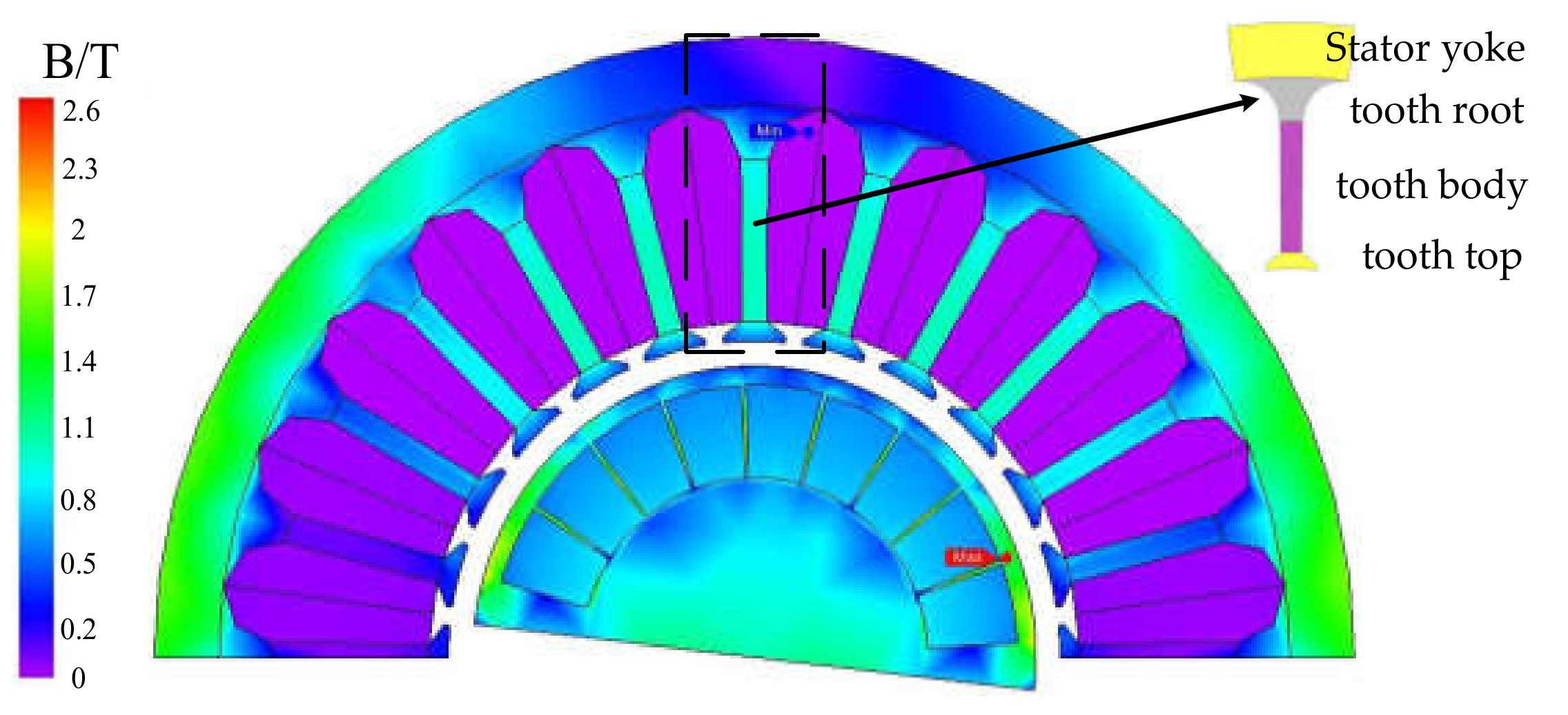
Figure 3.
Study position of the model.
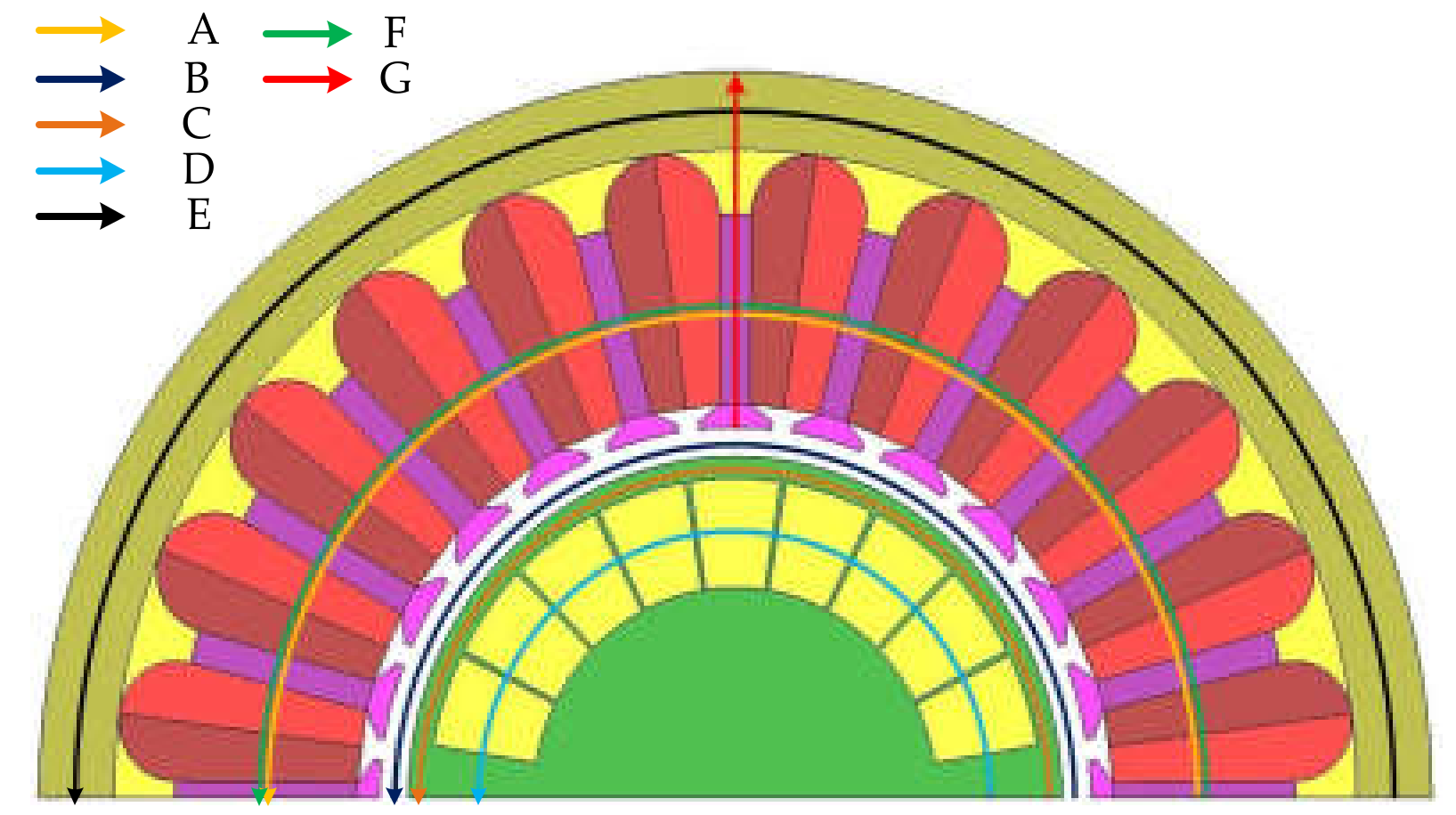
Figure 4.
Motor magnetic field distribution during no-load operation.
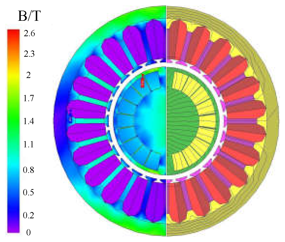
Figure 5.
Magnetic flux density in each region of the motor during no-load operation.

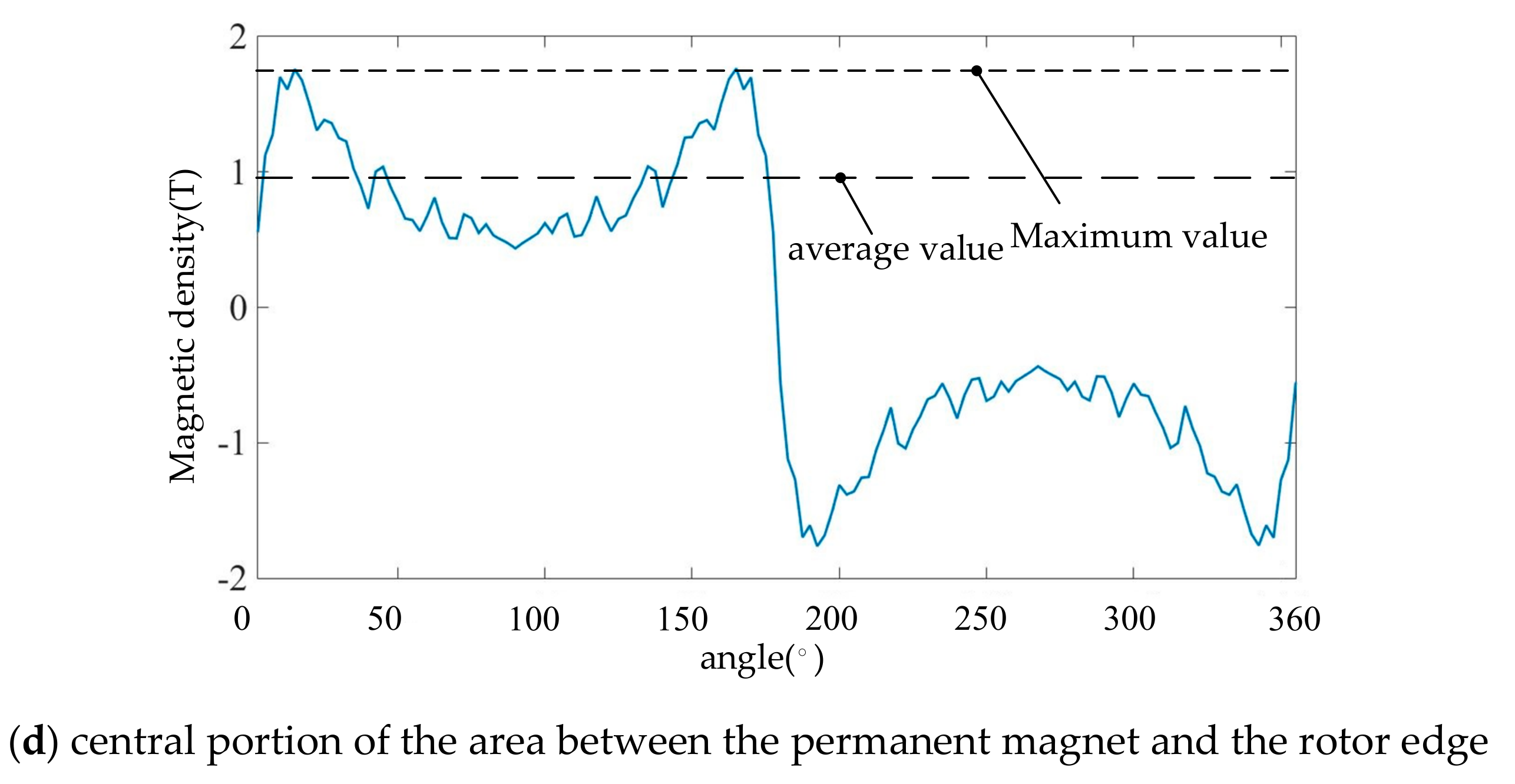
Figure 6.
Harmonic distribution of air gap tangential flux density.
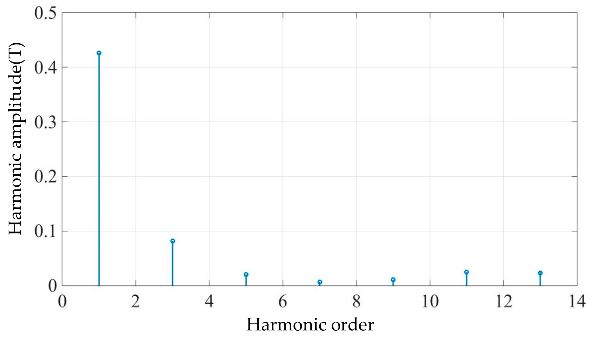
Figure 7.
Distribution of each odd harmonic in a period.

Figure 8.
Stator core loss distribution in each region during rated operation.
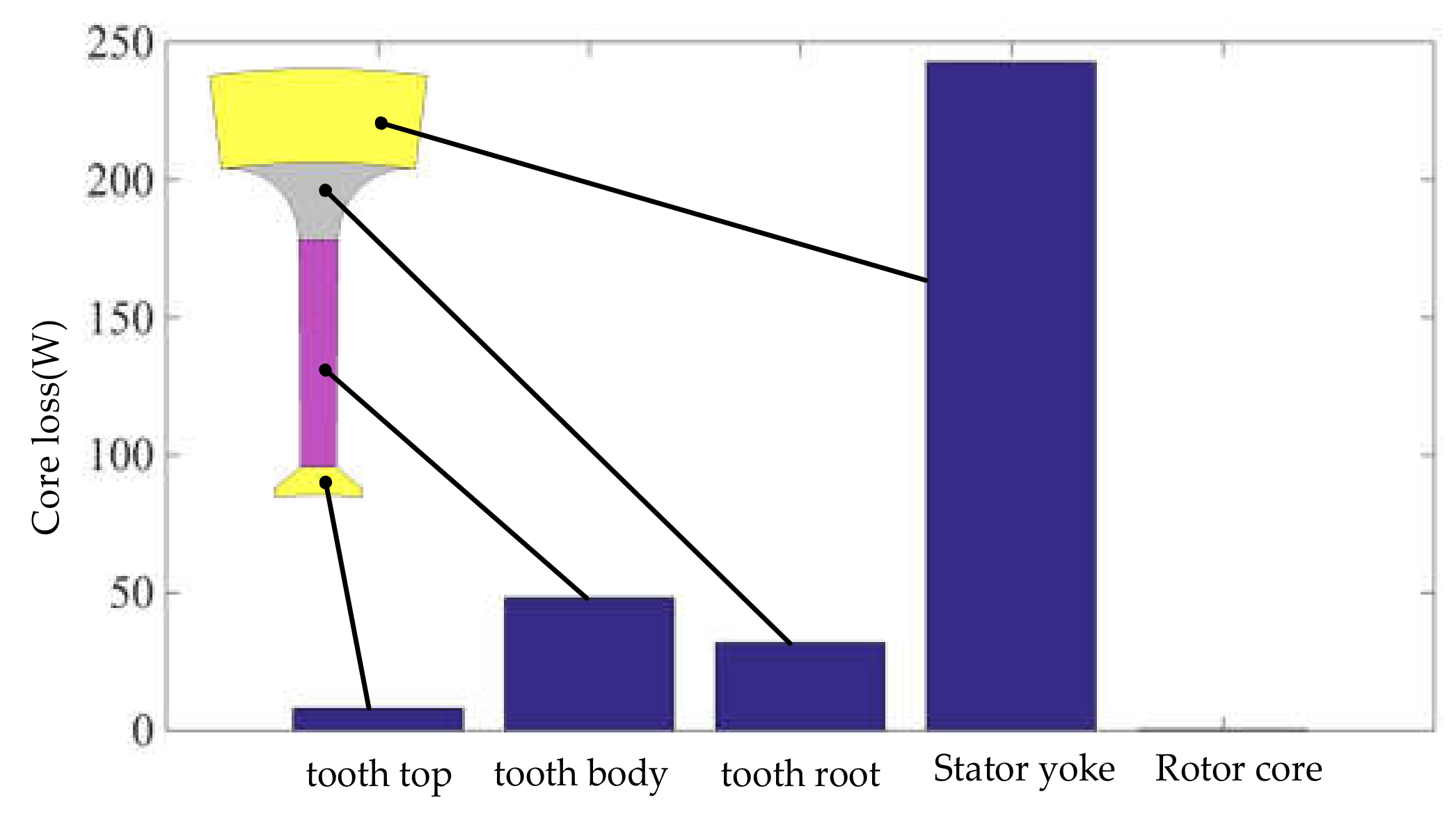
Figure 9.
Magnetic induction intensity distribution of motor in multi-load condition.
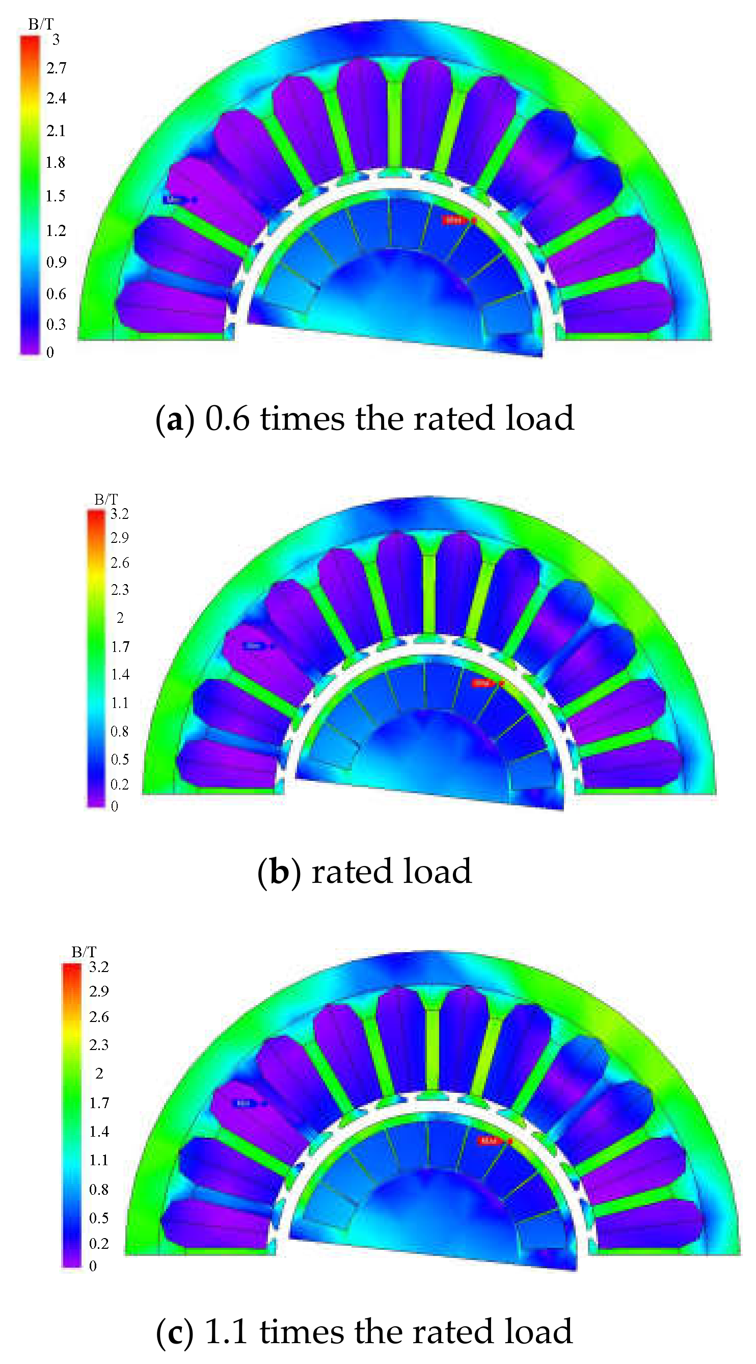
Figure 10.
Magnetic flux waveforms of stator teeth and yoke under four operating conditions.
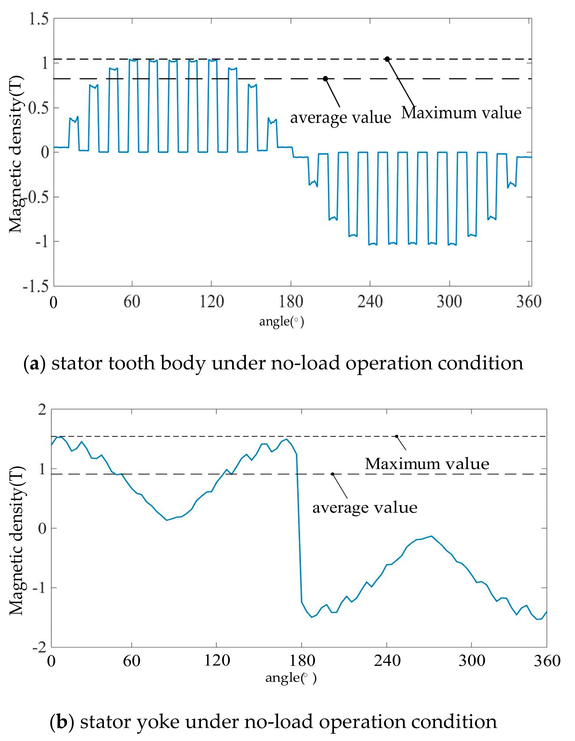
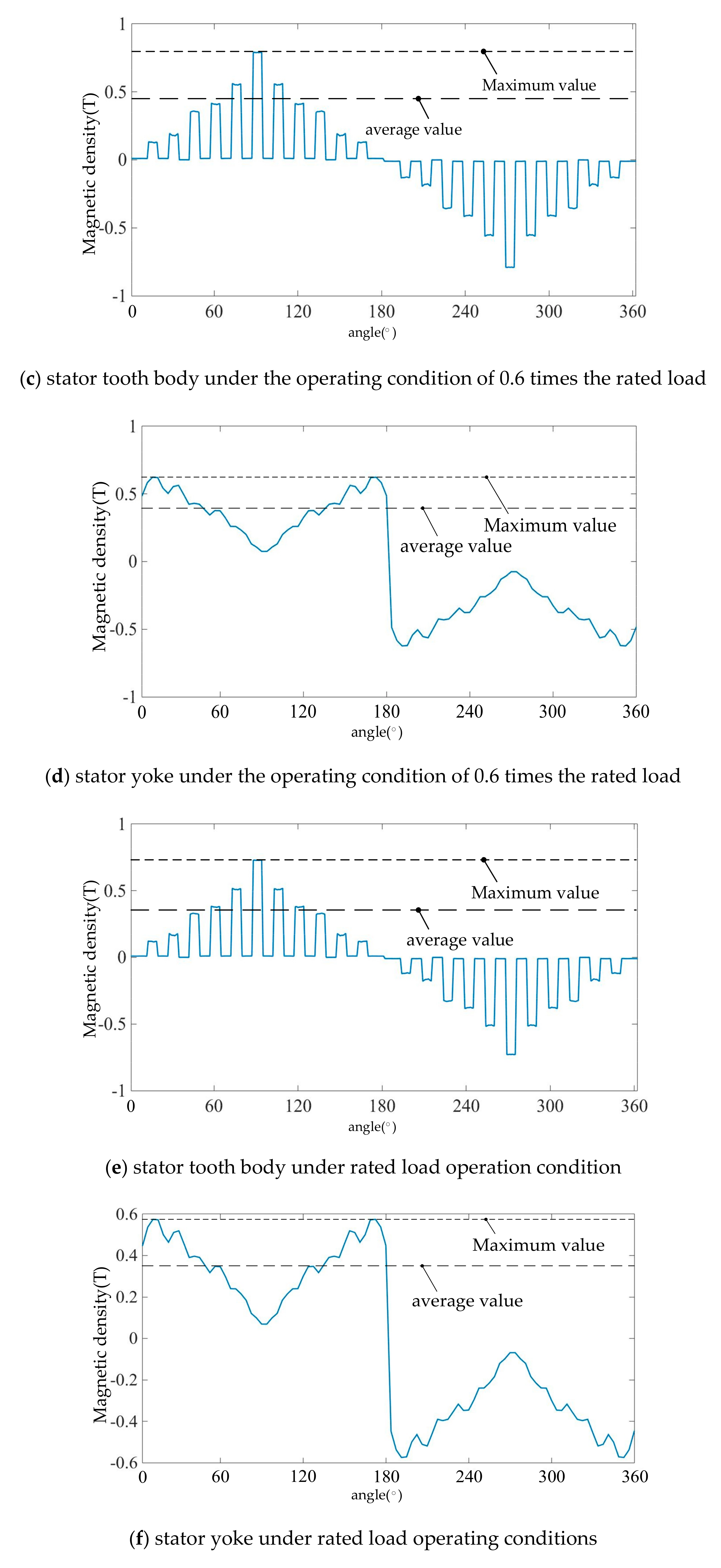
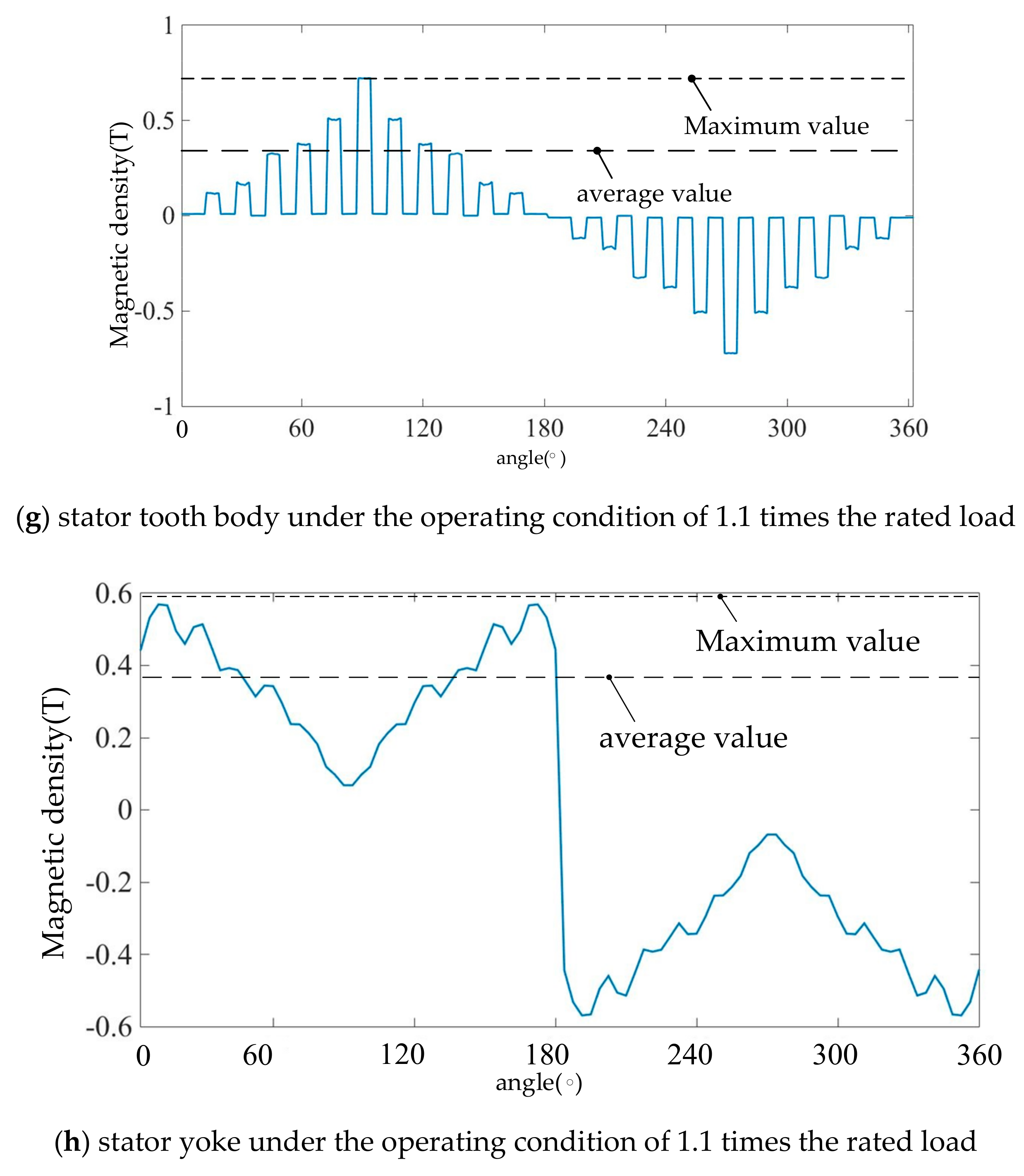
Figure 11.
Stator iron core loss changes in each region under four types of operating conditions.

Figure 12.
Flow diagram of motor iron loss-temperature field transition.


Table 1.
Parameters of prototype motor.
| Parameter | Value | Parameter | Value |
|---|---|---|---|
| Rated power/kW | 120 | Air gap length/mm | 4 |
| Rated voltage/V | 380 | Iron core length/mm | 112 |
| Rated frequency/hz | 400 | Number of poles | 2 |
| Stator outer diameter/mm | 200 | Number of stator slots | 24 |
| Rotor outer diameter/mm | 94 | Connection method | Y connection |
Table 2.
Magnitude of each harmonic and its proportion in the fundamental.
| Harmonic Order | Harmonic Amplitude/T | Proportion/% |
|---|---|---|
| One | 0.4265 | 100 |
| Three | 0.0813 | 19.06 |
| Fives | 0.0204 | 4.78 |
| Seven | 0.0068 | 1.59 |
| Nine | 0.0109 | 2.56 |
| Eleven | 0.0246 | 5.76 |
| Thirteen | 0.0233 | 5.46 |
Table 3.
Stator core loss distribution of motor during no-load operation.
| Divide Area | Iron Loss/W | Proportion/% |
|---|---|---|
| Stator tooth top | 8.02 | 2.42 |
| Stator tooth body | 48.21 | 14.56 |
| Stator tooth root | 31.71 | 9.58 |
| Stator yoke | 243.08 | 73.43 |
| Rotor core | 1 | 0.3 |
Table 4.
Average magnetic density of each area on the stator side under four operating conditions.
| Operating Conditions | Tooth Top/T | Tooth Body/T | Tooth Root/T | Yoke/T |
|---|---|---|---|---|
| no-load | 0.7618 | 0.965 | 0.5376 | 0.1808 |
| 0.6 times load | 0.5446 | 0.7385 | 0.4277 | 0.1747 |
| rated load | 0.5023 | 0.6811 | 0.3944 | 0.1611 |
| 1.1 times the rated load | 0.4974 | 0.6745 | 0.3906 | 0.1596 |
Table 5.
Stator iron core loss distribution in each region under four kinds of operating conditions.
Table 5.
Stator iron core loss distribution in each region under four kinds of operating conditions.
| Operating Conditions | Tooth Top/W | Tooth Body/W | Tooth Root/W | Yoke/W |
|---|---|---|---|---|
| no-load | 8.02 | 48.21 | 31.71 | 243.08 |
| 0.6 times load | 38.79 | 235.56 | 108.32 | 443.14 |
| rated load | 48.98 | 278.838 | 133.49 | 529.77 |
| 1.1 times the rated load | 51.27 | 286.62 | 138.34 | 547.83 |
© 2020 by the authors. Licensee MDPI, Basel, Switzerland. This article is an open access article distributed under the terms and conditions of the Creative Commons Attribution (CC BY) license (http://creativecommons.org/licenses/by/4.0/).
Share and Cite
MDPI and ACS Style
Tao, D.; Zhou, K.L.; Lv, F.; Dou, Q.; Wu, J.; Sun, Y.; Zou, J. Magnetic Field Characteristics and Stator Core Losses of High-Speed Permanent Magnet Synchronous Motors. Energies 2020, 13, 535. https://doi.org/10.3390/en13030535
AMA Style
Tao D, Zhou KL, Lv F, Dou Q, Wu J, Sun Y, Zou J. Magnetic Field Characteristics and Stator Core Losses of High-Speed Permanent Magnet Synchronous Motors. Energies. 2020; 13(3):535. https://doi.org/10.3390/en13030535
Chicago/Turabian StyleTao, Dajun, Kai Liang Zhou, Fei Lv, Qingpeng Dou, Jianxiao Wu, Yutian Sun, and Jibin Zou. 2020. "Magnetic Field Characteristics and Stator Core Losses of High-Speed Permanent Magnet Synchronous Motors" Energies 13, no. 3: 535. https://doi.org/10.3390/en13030535
Note that from the first issue of 2016, this journal uses article numbers instead of page numbers. See further details here.