Article

Evolution of Interior and Exterior Bearing Structures of the Deep-Soft-Rock Roadway: From Theory to Field Test in the Pingdingshan Mining Area

1
School of Mines, the Jiangsu Engineering Laboratory of Mining-Induced Seismicity Monitoring, China University of Mining and Technology, Xuzhou 221116, China
2
China Pingmei Shenma Energy Chemical Group Co., Ltd., Pingdingshan 467000, China
3
State Key Laboratory of Coal Resources and Safe Mining, China University of Mining and Technology, Xuzhou 221116, China
*
Author to whom correspondence should be addressed.
Energies 2020, 13(17), 4357; https://doi.org/10.3390/en13174357
Submission received: 2 June 2020 / Revised: 8 August 2020 / Accepted: 13 August 2020 / Published: 24 August 2020

Abstract

:
Pingdingshan mining area is one of the typical deep mining areas in China, and most of the mines in this area are troubled by the difficulties of the deep-soft-rock roadway support. Based on the concept of synergistic interactions of the interior and exterior bearing structure of the surrounding rock and, considering the specific geological conditions of the research site, we establish the mechanical model of the interior and exterior bearing structure of the roadway. Based on numerical simulation, we reveal the influence of main factors, such as support strength and mechanical characteristics, of surrounding rock on the distribution and evolution of the interior and exterior bearing structure. We found that increasing the support strength and mechanical parameters of surrounding rock can make the exterior bearing structure close to the roadway enhance the bearing characteristics of the interior and exterior bearing structure and improve the roadway stability. The distribution characteristics of the interior and exterior bearing structure of the roadway under six different support strengths and six different grouting parameters were systematically investigated by field measurements. According to the field test results, an effective strategy for controlling the deep-soft-rock roadway is proposed, which provides a good reference for surrounding rock control of the deep-soft-rock roadway in the Pingdingshan mining area and mines with similar mining conditions.

1. Introduction

With a further increase in the intensity of coal mining, the production of coal mines is gradually transferred to the deep. The deep rocks are mostly soft rocks, and the roadway, especially the soft-rock roadway, has poor stability under the long-term “three highs and one disturbance” environment. The surrounding rock is weak and broken and its bearing capacity is weak. Substantial studies have been carried out through theoretical studies and engineering practice on the interior and exterior bearing structures of the soft-rock roadway [1,2,3]. The fruitful results are mainly summarized in two aspects:
(1) The bearing characteristics of the surrounding rock of the deep-soft-rock roadway is comprehensively analyzed, and the main objects of the roadway support are defined. Nazimko, et al. [4,5,6,7] studied the failure process of the deep-soft-rock roadway and found that the surrounding rock has a tension area and a compression area. The compression area improves the stability of the roadway surrounding rock, whereas the tension area causes swelling, cracking, and shear failure of the surrounding rock. Kang [8,9] theoretically studied the stress distribution of circular roadways under high stress conditions. It was found that a tangential stress increase of 1–2 times of the roadway radius accounted for half of the total stress increase, the region of which was denoted as the critical bearing zone. It is pointed out that the thicker the bearing zone, the more uniform the stress distribution, and the more stable the roadway. Zhao [10] obtained theoretical expressions for predicting the plastic zone under different support strengths and non-uniform stress based on damage theory and a three-direction elastoplastic strain softening model. It is believed that the plastic zone and the stress distribution will effectively improve as the support strength increases. Zhang [11] revealed the characteristics of the double bearing structures of the surrounding rock, according to the stress characteristics. The radius of the exterior bearing structure equals the radius of the plastic zone. Xie [12] proposed that the “stress shell” phenomenon appears in the surrounding rock after excavation, through the scientific roadway layout and effective support means, and the roadway is arranged in the low stress area of the “stress shell”, which favors the roadway stability.
(2) Experimental studies on the control effect of the surrounding rock bearing structure on the deformation of the deep-soft-rock roadway were performed using the aspects of support method change [13], support material upgrading [14], and support technology optimization. The bearing capacity and the evolution mechanism of the interior and exterior bearing structures of the roadway was clarified. Wang [15] proposed a new high-strength, integral, and pressure-relief bearing structure concept and found that replacing U36 arched supports with concrete support structures can effectively increase the bearing capacity of the surrounding rock of the soft]-rock roadway. Jiao [16] proposed to add wire mesh and chemical grouting material after U-shaped steel to improve the bearing structure properties. Kang [17] analyzed the failure reasons of the bolting system in the soft-rock roadway and proposed to increase the performance of the support structure by increasing the diameter of the bolt (cable) and the preload. Jiang [18] designed a new type of grouting cable bolt with low resistance, large flow rate, and high efficiency to improve the load-bearing capacity of the surrounding rocks. Shen [19] used numerical simulation to optimize the parameters of the cable bolt, carried out field practice, and achieved good results of roadway deformation control.
The previous studies mostly discuss the distribution characteristic and the evolution mechanism of the interior and exterior bearing structures of the deep-soft-rock roadway from a theoretical aspect, but few factors are involved. However, the geological conditions of the deep-soft-rock roadway are generally complex and the existing researches are difficult to quantitatively guide the Pingdingshan mining area support scheme design. In addition, there are few literatures about the field observation index distribution characteristics of the interior and exterior bearing structures. In this paper, based on the production geological conditions of the deep-soft-rock roadway in the Pingdingshan mining area, the deformation of the surrounding rock is taken as the evaluation index to observe the evolution characteristics of the interior and exterior bearing structures under different support conditions through theoretical analysis and numerical calculation, and the support scheme of the deep-soft-rock roadway suitable for the Pingdingshan coal mine is put forward, which provides engineering practice cases and experience for mines with similar geological conditions.

2. Characteristics of Interior and Exterior Bearing Structures of the Roadway Surrounding Rock

2.1. Interior and Exterior Bearing Structures

Three zones, i.e., the broken zone, elastic zone, and plastic zone are developed radially from the interior outwards due to stress redistribution after roadway excavation. When reinforcement is completed, the interior and exterior bearing structures of the roadway surrounding rock are formulated [20]. As shown in Figure 1, the exterior bearing structure is the elastoplastic-zone rock approximating peak stress, including a small portion of the surrounding rock in the plastic zone and the whole elastic zone. The interior bearing structure is composed of the reinforced region due to bolting, grouting, and other supports, which contains the surrounding rock in the broken zone and most rock in the plastic zone.
According to the stress continuity equation of the elastoplastic zone, the radii of the roadway’s plastic zone and the broken zone are, respectively [20],
R s = R 0 [ ( ( σ R p + C cot φ ) ( σ C σ G Q + 1 ) 2 sin φ ( sin φ 1 ) ( 1 + η ) C cot φ + σ k 1 ) / ( P i + σ k 1 ) ] 1 k 1
R P = R s ( σ C σ G Q + 1 ) 1 1 + η
where R0, Rs, and Rp are the radii of the roadway, the broken zone, and plastic zone, respectively. σRp is the stress at the interface of the elastic-plastic zone. σ’ is the residual compressive strength of the surrounding rock. C is the cohesion of rock mass, φ is the angle of internal friction, Q is the strength softening modulus of the rock, and η is the expansion gradient of the surrounding rock in the plastic softening zone.
According to the theory of the critical load zone [9], assuming that the exterior bearing structure bears half of the load due to stress increase of the roadway surrounding rock, as shown in Equation (3), combining with the practical experience, the inner radius of the exterior bearing structure is defined when the tangential stress in the plastic zone is 1.1 times the original stress. Therefore, the inner and the outer radii of the exterior bearing structure are, respectively,
R b i R p ( σ θ p γ H ) d r + R p R b 0 ( σ θ e γ H ) d r = 1 2 R d R p ( σ θ p γ H ) d r + 1 2 R p ( σ θ e γ H ) d r
1.1 γ H = 1 + sin φ 1 sin φ ( σ R p + C cot φ ) ( R b i R p ) 2 sin φ 1 sin φ C cot φ
γ H = 1 + sin φ 1 sin φ ( σ R p + C cot φ ) ( R d R p ) 2 sin φ 1 sin φ C cot φ
where Rd is the inner radius of the stress-increase area, γ is the bulk density of the overlying rock layer, H is the buried depth of the roadway, θ is the polar angle, and σθp is the tangential stress in the plastic zone. According to Equations (3)–(5), the inner and outer radii, Rbi and Rb0, of the exterior bearing structure can be obtained.
The external bearing structure primarily sustained the load of the stress-increase zone of the surrounding rock of the roadway. In-situ practice [21] demonstrated that the more uniformly distributed the exterior bearing structure, the closer the roadway; therefore, the more stable the roadway.

2.2. Influencing Factors and Sensitivity Analysis of the Bearing Structures

According to the calculation equations of the interior and exterior bearing structures, the main factors affecting the bearing structures of the roadway are the support strength and mechanical properties of the surrounding rock. Different factors have different sensitivities to the zoning characteristics of the bearing structures. Figure 2 shows the effects of Rs, Rp, Rb0, and tb (tb = Rb0-Rs) under different support strengths (Pi) and mechanical properties of the surrounding rock (represented by C and φ) on the zoning of the bearing structures.
Figure 2 shows that: (1) As the support strength increased, the radii of the broken zone and the plastic zone gradually decreased and the decrease ratio became smaller. The radius of the exterior bearing structure was less sensitive to the support strength. When the support strength was 0.1 MPa to 0.3 MPa, for each increase of 0.05 MPa in support strength, Rb0 decreased by 6.87%, 6.69%, 5.89%, and 4.48%, respectively.
(2) As the mechanical properties (C and φ) of the surrounding rock grew, both the radii of the broken zone and the plastic zone decreased significantly. The exterior bearing structure was close to the roadway and its radius was more sensitive to the cohesion of surrounding rock. When the cohesion was 1.5 MPa to 3.5 MPa, the outer diameter Rb0 of the exterior bearing structure decreased by 10.22%, 16.41%, 18.21%, and 32.57%, respectively, when the cohesion increased by 0.5 MPa.

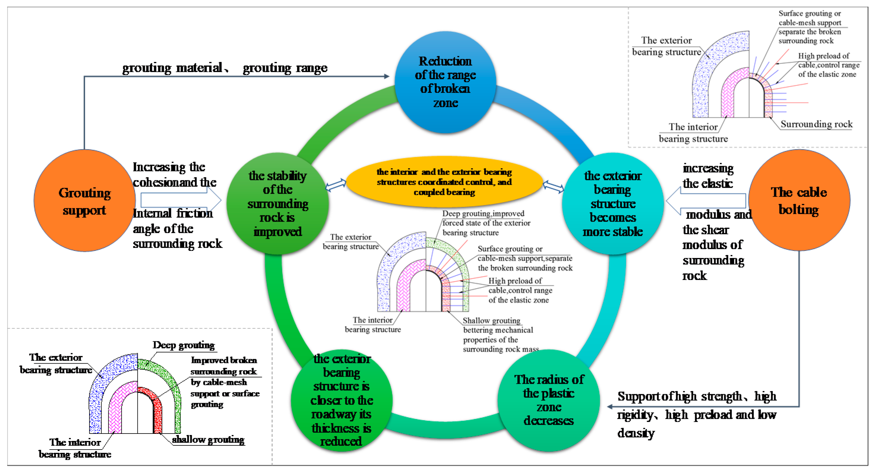
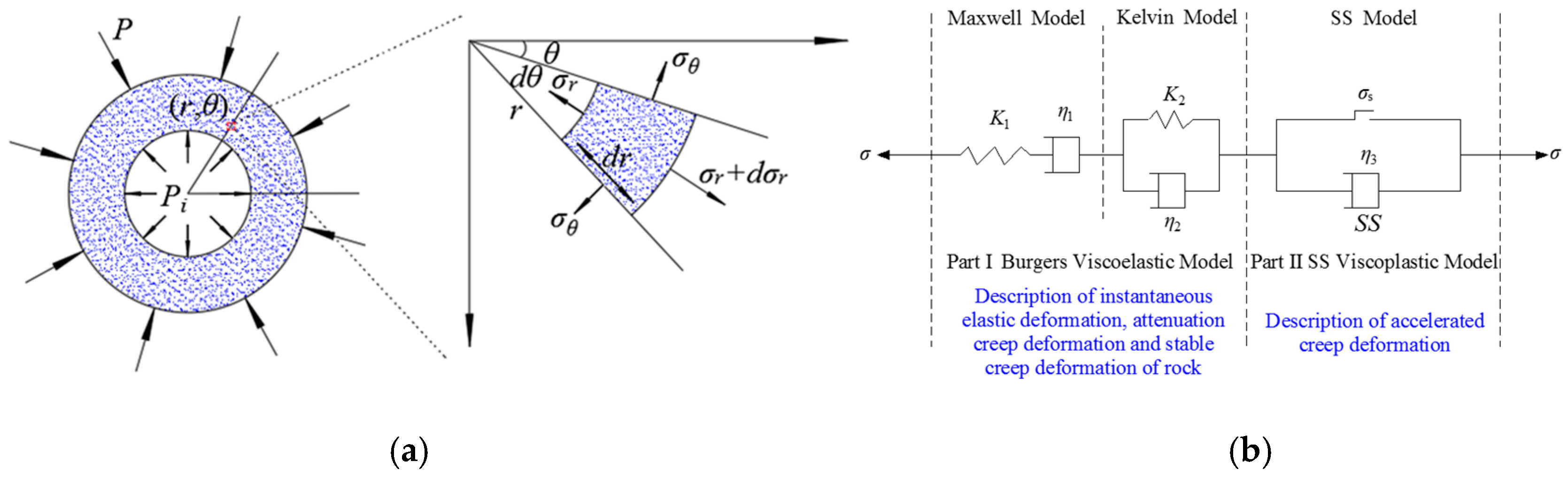
2.3. Evolution of the Bearing Structures

Based on the sensitivity analysis above, the evolution of the interior and exterior bearing structures were studied from the perspectives of improving the stress state of the interior bearing structure, timely active support to mitigate creep of the soft rock, and bettering the integrity and mechanical properties of the surrounding rock mass.
Figure 3 illustrates that the interior and exterior bearing structures of the roadway surrounding rock featured inter-dependence, coordinated control, and coupled bearing. The interior and exterior bearing structures did not exist independently. The exterior bearing capacity improved at different degrees, while the stability of the interior bearing structure enhanced. The interior bearing structure was more stable, while the exterior bearing structure strengthened. The interaction between the interior and the exterior bearing structures ensured the safety and stability of the deep-soft-rock roadway. Their evolution characteristics were closely related to the support pattern. As the exterior bearing structure became more stable, the radius of the plastic zone decreased accordingly. At this time, the exterior bearing structure was closer to the roadway, its thickness reduced, and the stability of the surrounding rock improved. The radius of the plastic zone decreased. When the interior bearing structure was stable, it provided higher radial stress to the exterior bearing structure and enhanced its bearing capacity. The grouting support enhanced the stability of the exterior bearing structure by increasing the cohesion and the internal friction angle of the surrounding rock and reducing the radius of the broken zone. The cable bolting improved the stability of the exterior bearing structure by increasing the elastic modulus and the shear modulus of the reinforced region. The stability of the structure reduced the radius of the plastic zone. The sequential effect and coupled bearing of the interior and exterior bearing structures effectively reduced the radii of the broken zone and the plastic zone, which enhanced its bearing capacity and thus ensured the good condition of the roadway.

3. Evolution of the Interior and Exterior Bearing Structures of the Deep-Soft-Rock Roadway

In this section, based on the geological conditions of the Pingdingshan mining area, the widely-used commercial software, FLAC3D, was used to simulate and analyze the distribution characteristics of the bearing structures of the roadway surrounding rock under different mining conditions.

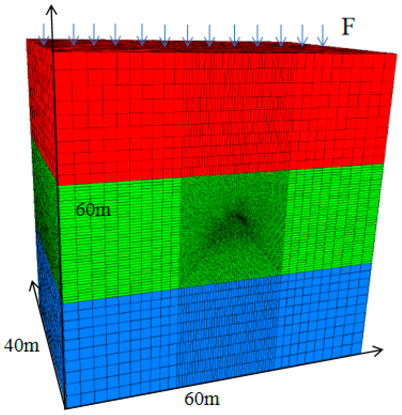
3.1. Numerical Model

To further clarify the impact of different mining conditions on the evolution of the bearing structures, the numerical model of FLAC3D in Figure 4 was established. Since the roadway was far away from the coal seam, the influence of coal seam extraction on the roadway was not considered in this paper. In addition, the research area of the model was the crosscut and the return air uphill. The protective coal pillar between the roadways was wide enough, so the influence of roadway excavation was not considered in this paper. Although the roadway was located near the shaft station, the interaction between the roadways was considered in the design of the roadway and the stability of the roadway was not affected. The model dimension was 60 m × 40 m × 60 m (length × width × height). The roadway was structured using vertical walls with an arch dome with a dimension of 5 m (width) × 3.5 m (height). All the boundaries of the model were restrained, except the top was free. The lateral pressure coefficient was 1.0. The mechanical properties of the rock layers are listed in Table 1.
By varying the support strength and mechanical parameters of the surrounding rock, the distribution characteristics of the interior and exterior bearing structures were examined. The surrounding rock mass of the deep roadway had low strength and was locally seriously damaged. Cohesion reflected the degree of rock integrity. Therefore, the cohesion can be taken as an example to discuss the influence of the mechanical properties of the surrounding rock mass on the distribution characteristics of the interior and exterior load-bearing structures. The support scheme is given as below.
(1) Cable bolting was adopted. In order to study the evolution process of the interior and exterior load-bearing structures, the row spacing ranged from 700 to 1000 mm and the pre-tightening force ranged from 70 to 100 kN. The calculated supporting strength was 0.083 MPa, 0.09 MPa, 0.1 MPa, 0.109 MPa, 0.116 MPa, 0.125 MPa, 0.137 MPa, 0.147 MPa, 0.158 MPa, and 0.175 MPa, respectively.
(2) The mechanical properties of the roadway surrounding rock were changed to study the evolution of the bearing structures. After many measurements and calculations, the cohesion of the surrounding rock was 2.5–4.8 MPa, so the cohesions of the roadway surrounding rock were set to be 2 MPa, 2.4 MPa, 2.8 MPa, 3.2 MPa, 3.6 MPa, 4.0 MPa, 4.4 MPa, and 4.8 MPa, respectively.

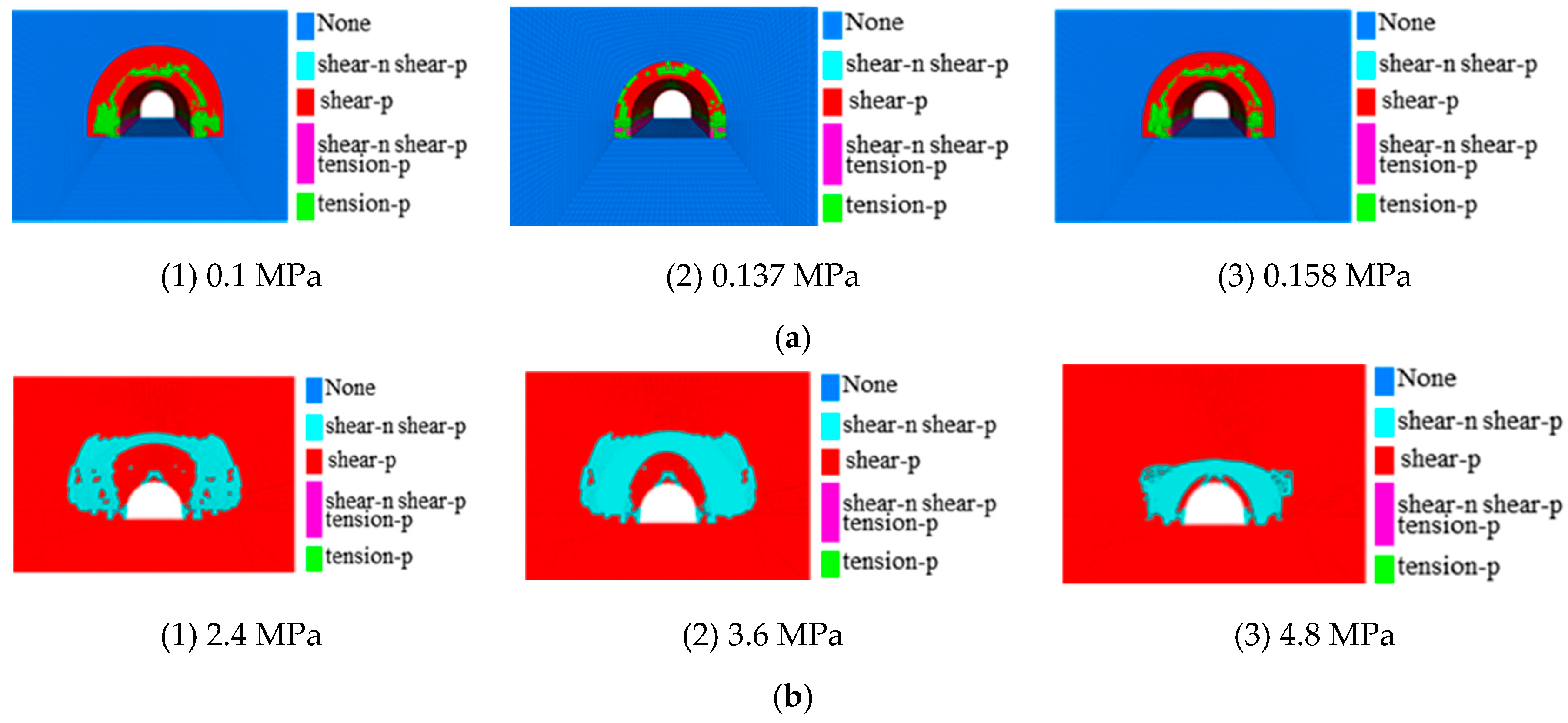
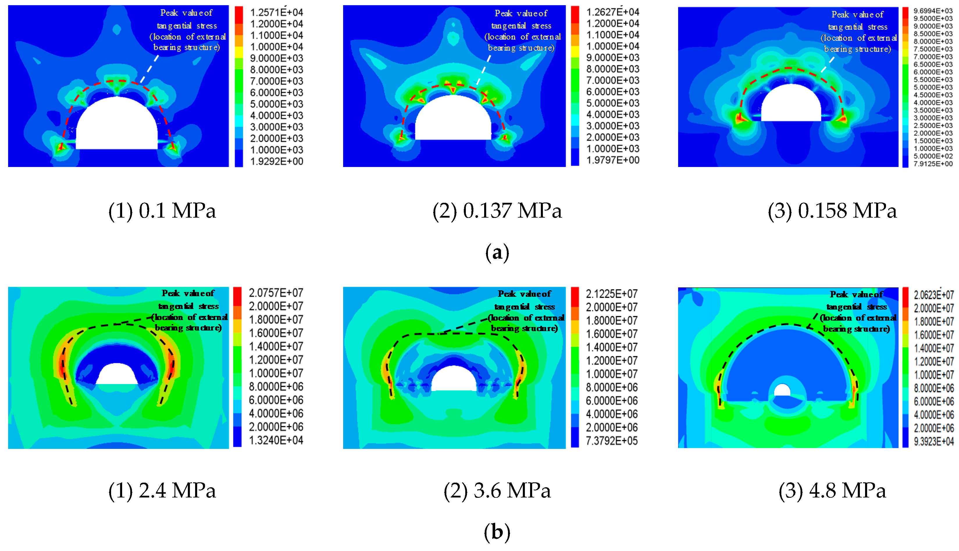
3.2. Bearing Structure Evolution

Section 2.1 shows that the exterior bearing structure was located in stress-increase area of the roadway surrounding rock. The tangential stress of the roadway rib was vertical stress. Thus, the region of the exterior bearing structure can be determined based on the stress-increase area and the peak tangential stress. Figure 5 and Figure 6 show the distribution of the plastic zone and the distribution of the tangential stress under different support strengths and the cohesions of the surrounding rock.
Figure 5 and Figure 6 show that, with the increase of support strength and surrounding rock mechanical properties, both the deformation of surrounding rock and the radius of the plastic zone declined. The peak tangential stress gradually approached the roadway, and the range of the stress-increased area of the tangential stress decreased. In combination with Section 2.1, the radius of the external bearing structure of the surrounding rock reduced, the bearing capacity of the surrounding rock increased, and the deformation of the surrounding rock descended, and the reduction trend was consistent with the change characteristics of the plastic zone radius. Taking the change of the support strength as an example, when the support strength was 0.083 MPa, 0.09 MPa, 0.1 MPa, and 0.109 MPa, the roof convergence decreased by 20.3%, 17.6%, 15.3%, and 13.1%, respectively. When the support strength increased from 0.158 to 0.175 MPa, the roof convergence decreased by 11.5%. The effect of support strength increase on the roof convergence was less remarkable.
Figure 7 shows that the distance of the peak tangential stress to the roadway side was roughly proportional to the plastic zone radius. Based on the above analysis, it can be considered that the radius of the exterior bearing structure was generally proportional to the magnitude of roadway deformation. The following employs the deformation of surrounding rock as an indicator to reflect the distribution of the bearing structures. Cable bolting and grouting in the Pingdingshan mining area were used, and the evolution of the bearing structures was examined in-situ.

4. Evolution of the Bearing Structures under Different Support Strengths

Based on the above analysis, this section uses the surface displacement of surrounding rock as an indicator to observe the distribution characteristics of bearing structure of the surrounding rock under different support strengths to determine the best support approach for controlling the evolution of the bearing structures in the Pingdingshan mining area to ensure safe operation and regular production.

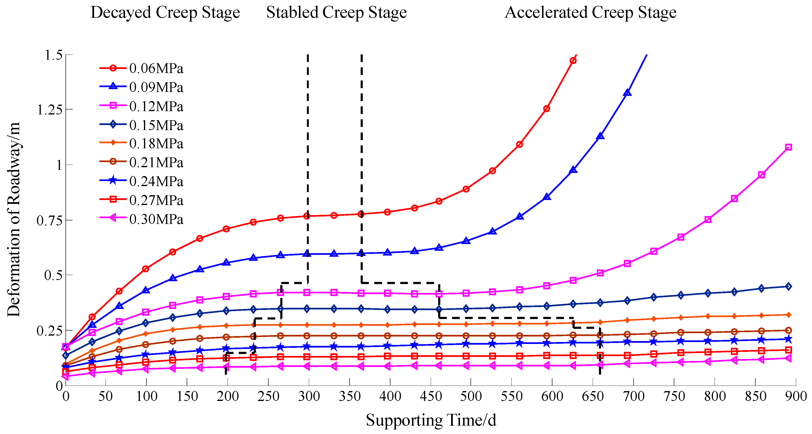
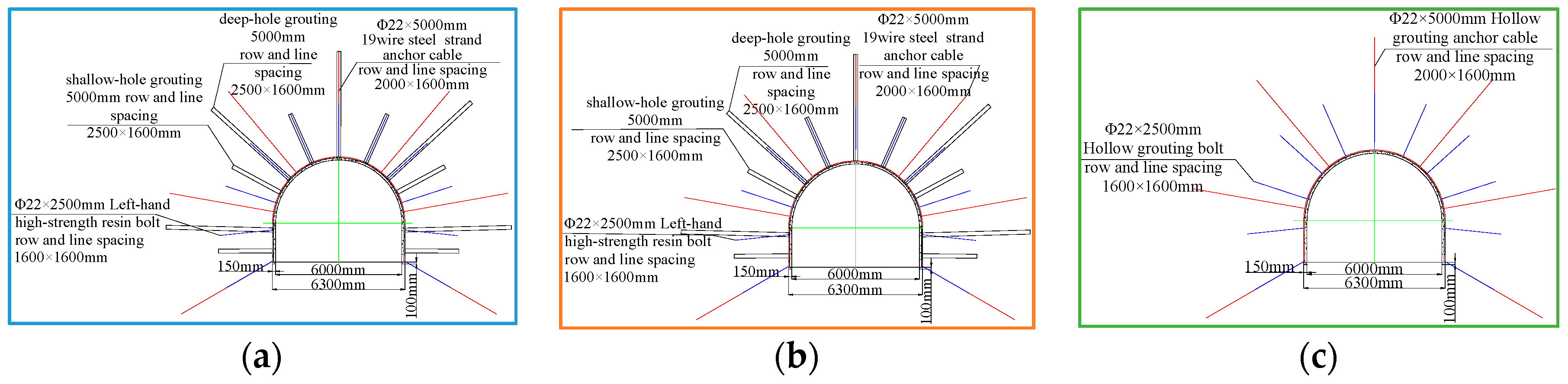
4.1. Deformation of Deep-Soft-Rock Roadway under Different Support Strengths

For deep-soft-rock roadways, the surrounding rock rheology is more significant and the support is time-dependent. We took an infinitesimal element of rock for analysis, as shown in Figure 8a. In this section, the improved Burgers model was used to analyze the deformation of the surrounding rock. The mechanical model was shown in Figure 8b. The constitutive model was composed of two parts. The first part was the Burgers model, which was used to describe the instantaneous elastic deformation, attenuated creep deformation, and stable creep of the soft rock. The second part was the SS viscoplasticity model, which represents the deformation characteristics of the post-peak creep. The SS model follows the plastic strain softening flow.
Assuming a small deformation occurs on the infinitesimal element, applying the principle of superposition, the constitutive equation of the mechanical model in Figure 8 is obtained:
2 η 2 e i j + 2 K 2 e i j = η 2 K 1 s i j + [ 1 + K 2 K 1 + η 2 η 1 + η 2 η 1 ( 1 σ y σ e q ) ] s i j + [ K 2 η 1 + η 2 σ y σ e q η 3 ( σ e q ) 2 + K 2 η 3 ( 1 σ y σ e q ) ] s i j
where Sij and eij are the stress partial tensor and strain partial tensor, respectively. S i j and S i j are the first and the second derivatives of the partial tensor, with respect to time, respectively. e i j and e i j are the first and the second derivatives of the strain partial tensor, with respect to time, respectively. σy is the radial stress at r.
At the moment when the load is applied, i.e., when excavation is made, t = 0+. Two initial conditions are obtained:
s i j 0 = 2 K 1 e i j
e i j 0 = [ 1 2 η 1 + 1 2 η 2 + 1 2 η 3 ( 1 σ y σ e q ) ] s i j 0 + 1 2 K 1 s i j 0
The superscript 0 in the equations indicates the magnitude of the surrounding rock upon loading.
For plane axisymmetric problems, the equilibrium equation for stress is:
d σ r d r + σ r σ θ r = 0
The geometric equations are:
ε r = d u r / d r   and   ε θ = u r / r
The compatibility equation expressed by strain is:
ε θ / r + ( ε θ ε r ) / r = 0
Assuming that the relative volume does not change when the rock mass is deformed, we have:
ε θ = ε r   and   σ z = ( σ θ + σ r ) / 2
The expressions of strain and displacement is obtained by the combing Equations (9)–(12):
ε θ = ε r = f ( t ) / r 2 ( r r 0 )
u = f ( t ) / r
In the equation, u is the roadway displacement and f(t) is the roadway displacement at time t.
The stress boundary condition is:
σ r | r = r 0 = P i ( t )   and   σ r | r = = P
where Pi(t) is a function representing the variation of support strength along with time and P is the rock original stress.
Considering the extremely slow change of the boundary of the viscoplastic zone with time, the bearing structures are coordinated to maintain dynamic balance. The expression of the roadway displacement f(t) can be obtained at any time in the viscoplastic zone:
f ( t ) = R s 2 Q e [ 1 2 K 1 + 1 2 K 2 ( 1 e K 2 η 2 t ) + Q e σ s η 3 t n ]
In the equation, Rs is the radius of the plastic zone, Qe represents the support strength, and n is the creep index with a value of 1.021 [22].
Substituting Equation (16) into Equation (15), the rock deformation is:
u = R s 2 r Q e [ 1 2 K 1 + 1 2 K 2 ( 1 e K 2 η 2 t ) + Q e σ s η 3 t n ]
The relationship between the deformation of the surrounding rock and the supporting strength of the soft-rock roadway in the Pingdingshan mining area is shown in Equation (13). This relationship is suitable for the rock in the typical deep-soft-rock roadway of the Pingdingshan mining area.
Assuming the radius of the roadway radius is 2.5 m, the cross-sectional area is 19.6 m2. To ensure mining safety, the maximum allowable deformation of the roadway in the Pingdingshan mining area is 30% of the cross-section area, which means that the minimum cross-sectional area of roadway is 13.7 m2 and the radius of the roadway is 2.1 m. That is, the maximum allowable surface displacement of the surrounding rock mass is 0.4 m in the Pingdingshan mining area. Considering the surrounding rock is sandy mudstone, we have K1 = 3.39 GPa, K2 = 13.7 GPa, η1 = 4.52 GPa/h, η2= 4.95 GPa/h, and η3 = 1395 GPa/h using the creep test and model parameter fitting. Introducing the above parameters into Equation (17), Figure 9 calculates the deformation of the surrounding rock with different support strengths.
Figure 9 shows the deformation time curves of the surrounding rock under different support strengths. Generally, the deformation time curve can be categorized into the acceleration-type curve and the stable-type curve. During the maintenance period of about 900 days, the deformation curve of the roadway surrounding rock belonged to an accelerated type when the support strength was less than 0.15 MPa. The roadway deformed rapidly until it failed. When the support strength exceeded 0.5 MPa, the deformation time curves were all stable types. The roadway deformation gradually became unvaried. If the support strength increased, the difference in the roadway deformation in a short period was not significant. However, the attenuation creep stage was less, and thus the stable creep stage became longer. Theoretical results show that when the support strength of 0.15 MPa was used, the deformation of about 0.4 m still occurred after the roadway was maintained for about 900 days, which cannot guarantee safe production. For the current situation, that the support strength could not be too high in the field, we temporarily took the best support strength at 0.18 MPa, and the roadway deformation was small at this time, which can meet the safe operation.

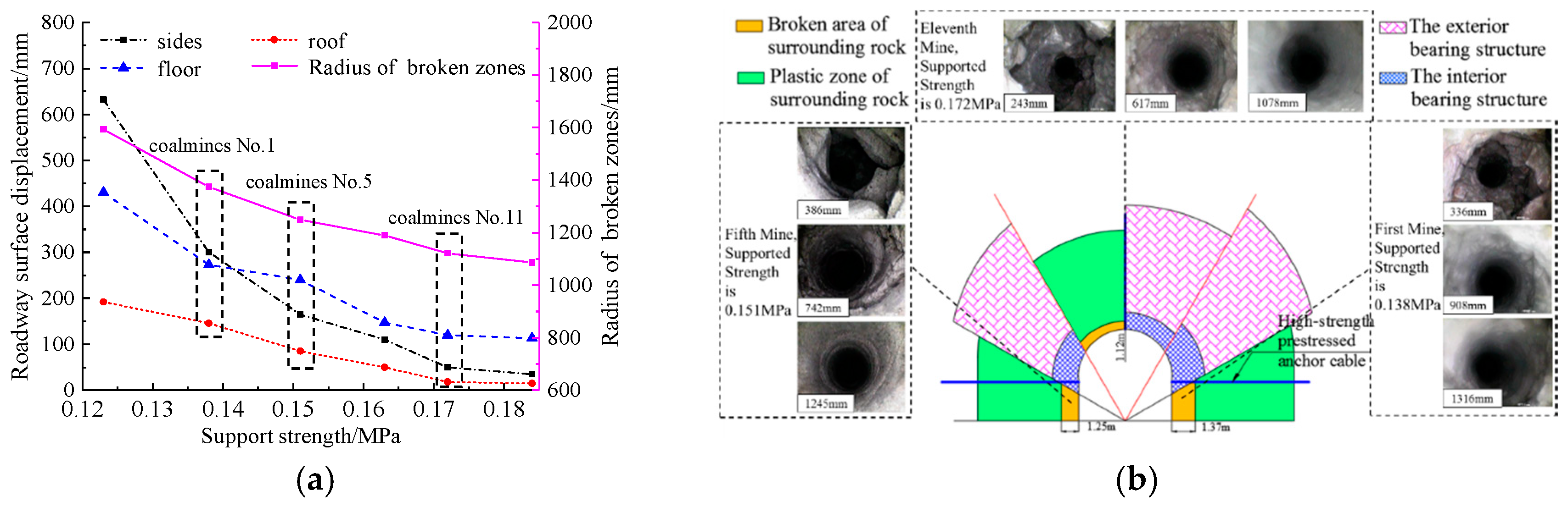
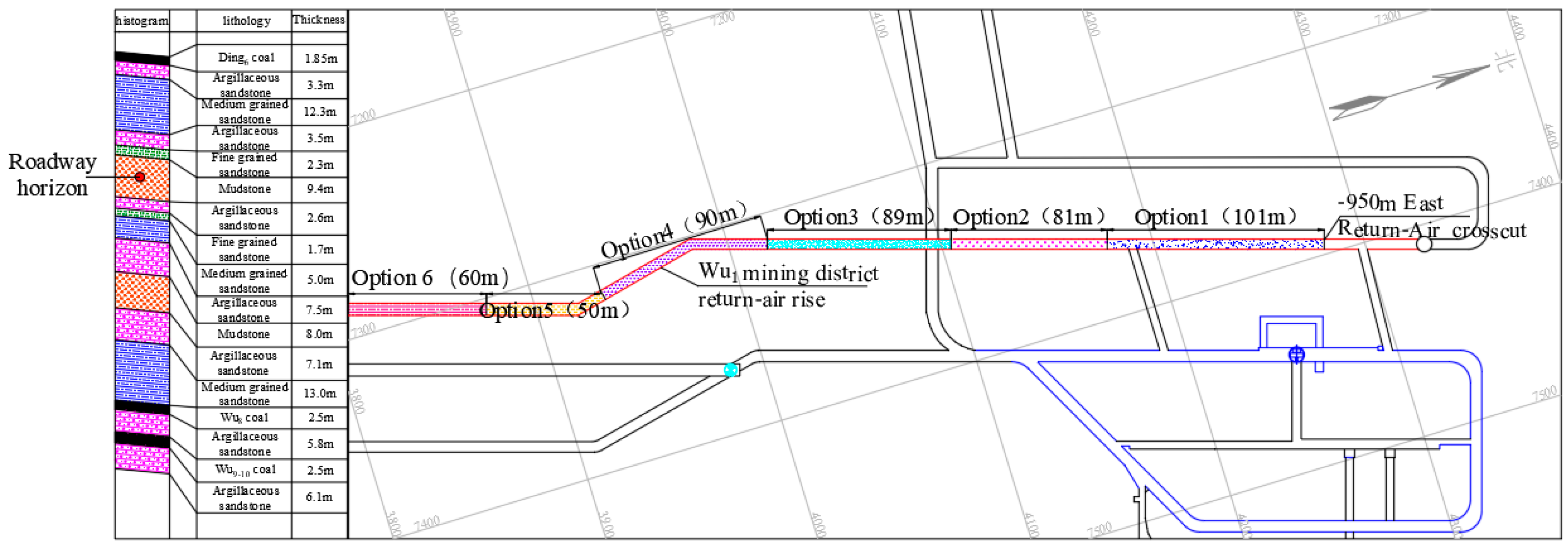
4.2. Field Test and Bearing Structure Evolution

The coal seam groups, E and F, of the Pingdingshan mining area were deep buried with high stress concentration. The surrounding rocks were mostly sandy mudstone and mudstone. We used different cable support patterns of the six roadways in the Pingdingshan mining area to study the relationship between the support strength and the surface displacement of surrounding rock. The buried depth and surrounding rock mechanical properties of six test roadways were the same and they were supported by the same anchor cable type. The surface displacement of surrounding rock was monitored using the “cross measurement method” for three months after support was completed. The roadway location, support pattern, and field test results are shown in Table 2, and some roadway surface displacement and borehole peep are shown in Figure 10.
The support schemes of six test roadways adopted bolt mesh cable support. The specifications of bolt mesh in each roadway were consistent, and the row spacing and preload of anchor cables were different. We took the downhill rail roadway in the coalmine No.5 as an example. The roadway cross-section was structured as vertical walls with an arch dome, and the net width and height were 6000 mm and 4850 mm, respectively. The 1 × 19 − Φ21.6 × 6500 mm-type high-strength hollow cable was used in the roof, and the row spacing was 800 × 800 mm. The mesh adopted Φ6 reinforced wire, the row spacing was 80 × 80 mm, and the lap length was no less than 100 mm; the cable adopted Φ22 × 8000 mm 19 wire-stranded steel in two sides of coal and the row spacing was 1600 × 1600 mm. A total of 9 cables were installed per row.
According to the field practice results in Table 2 and Figure 10, it can be seen that the surface displacement of surrounding rock gradually decreased with the increase in support strength and the decrease was negatively dependent on the support strength increase. When the support strength exceeded 0.172 MPa, the effect of the support strength increase on the surface displacement of surrounding rock was not apparent. Figure 10b shows that the increase of the support strength reduced the radii of the roadway broken zone and the bearing structures. The radii of the broken zones of the tested roadways in coalmines No.1, No. 5, and No. 11 were 1373.76 mm, 1288.87 mm, and 1121.27 mm, respectively. Increasing the support strength can effectively reduce the broken zone and improve the stability of the interior bearing structure. Considering that the support strength in the field cannot be too high, it is believed that support strengths of 0.17 MPa to 0.18 MPa can effectively mitigate the deformation of the roadway surrounding rock, enhancing the bearing capacity of the external bearing structure. Combining with mesh, the stability of the interior bearing structure was improved and the area of the plastic zone was reduced, which brought the exterior bearing structure closer to the roadway. Thus, the deformation of the surrounding rock of the roadway was controlled and its stability was maintained.

5. In-Situ Observation on the Evolution of the Bearing Structures under Different Grouting Methods

To address the poor performance of the cable-mesh-spraying support on the soft and broken surrounding rock, the surface displacement of surrounding rock was used as an indicator to conduct field tests in the Pingdingshan mining area for studying the effect of grouting the distribution characteristics of the bearing structures. The grouting support patterns for the deep-soft-rock roadways were then determined in the Pingdingshan mining area to ensure safe operation.

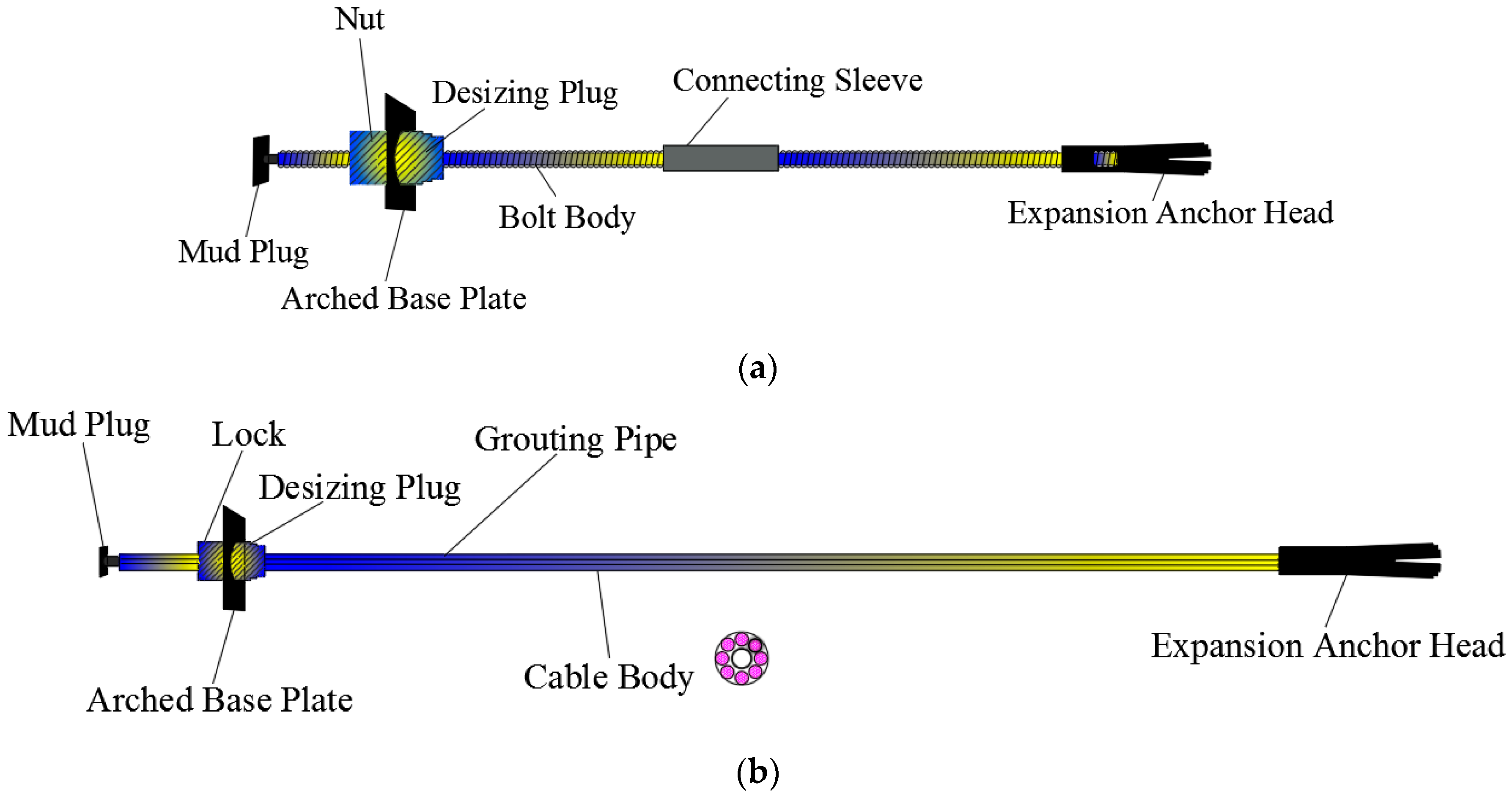
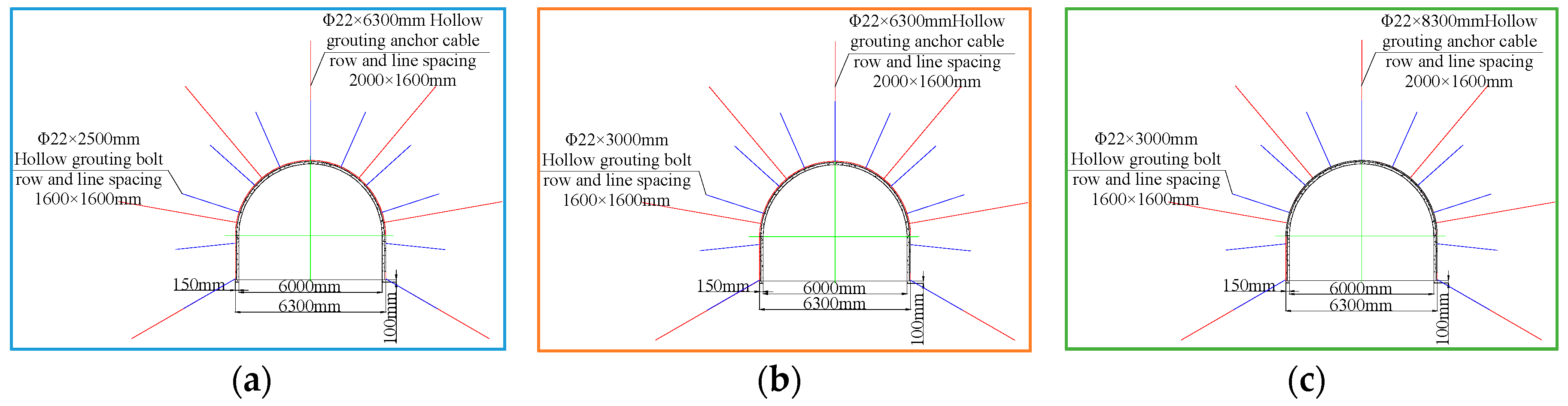
5.1. Grouting Support and Materials

When the surrounding rock was broken, the support strengths of 0.17 MPa to 0.18 MPa, using cable-mesh-spraying, did not work well for the surrounding rock. The roadway stability can be improved by grouting. Slurry entering the cracks of the rock mass can effectively improve the mechanical properties of the broken surrounding rock, reduce the range of the broken zone, enhance the stability of the interior bearing structure, provide greater radial stress to the exterior bearing structure, reduce the radius of the plastic zone of the surrounding rock, and then control deformation of the surrounding rock [23]. The procedures of sequential shallow-and-deep grouting for soft and broken surrounding rocks were proposed and implemented. Sequential shallow-and-deep grouting meant that the shallow grouting was carried out first to the full cross-section of the roadway. Deep grouting was implemented after the surrounding rock in the shallow region was stabilized. Figure 11 illustrates the sequential shallow-and-deep-grouting.
To address the weaknesses of ordinary grout bolts in reinforcing the broken zone, hollow-grouting bolts and hollow-grouting cables (Figure 12) were used and field tests were conducted in the Pingdingshan mine area. The grouting pressure was controllable in order to improve the grouting extent and the compaction effect. Low grouting pressure was used for roadways in soft-rock masses, in which the pressure was no less than 3 MPa and the flow rate was no less than 50 L/min, with the purpose of ensuring the grouting slurry fully seeped through the rock mass. The grouting sequence adopted the pattern of staggered grouting. The roof, the upper part, and the cable bolts were grouted after the grouting operations of the rib, the lower part, and rock bolts, respectively. This was to enhance the grouting amount in the coal and rock mass and achieve the objectives of multiple grouting reinforcement and complementary grouting between deep and shallow support.

5.2. Grouting Support in the Field

The rocks of the east air-return roadway and uphill roadways in the coalmine No. 1 of the Pingdingshan mining area were mudstone and sandy mudstone. The rocks were relatively soft and broken, and the integrity was poor. Large deformation cannot meet the requirements of safe production. In this section, six test schemes were carried out for on-site practice to study the grouting in six sections of the east air-return gate, 58 m to 159 m, 159 m to 240 m, and 240 m to 329 m, and air-return uphill, 0 to 90 m, 90 m to 140 m, and 140 m to 200 m, respectively. The effect of materials and grouting area on the distribution characteristics of the bearing structures of the roadway and borehole observation and the test roadways are all semi-circular arched with a net width of 6000 mm and a net height of 4850 mm. The roadway location is shown in Figure 13.

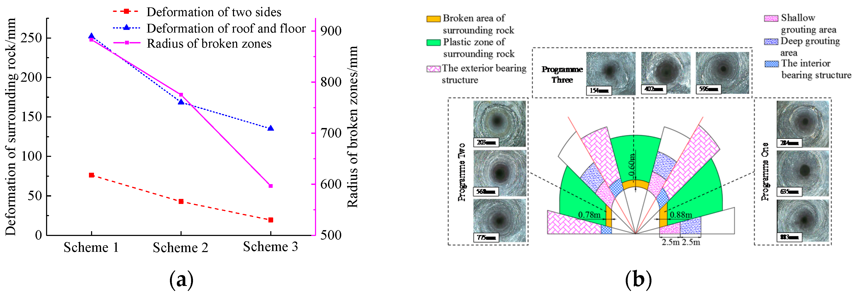
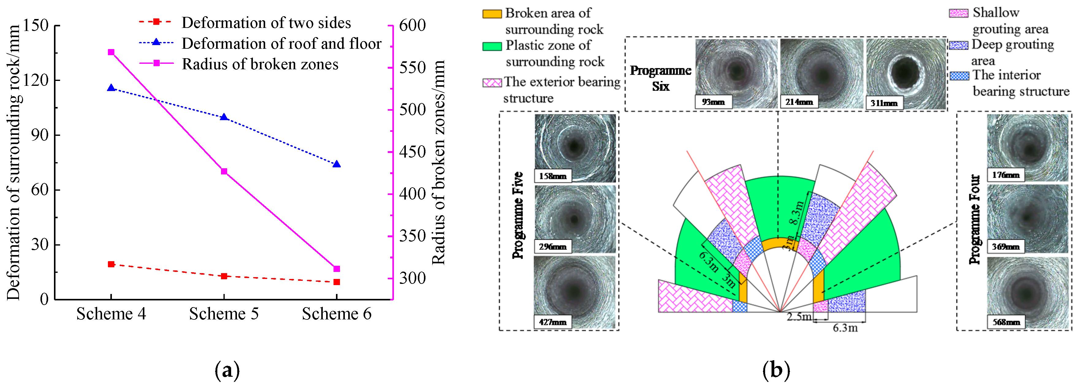
5.3. Effect of Grouting Schemes on the Bearing Structures

Three grouting schemes were established, and field tests were carried out in the 58 m to 159 m, 159 m to 240 m, and 240 m to 329 m sections of the Level-3 east air-return roadway. The Scheme 1 used the support of “cable-mesh-spraying + shallow-hole grouting (2.5 m) + deep-hole grouting (5 m)”, the Scheme 2 used the support of ”cable-mesh-spraying + grouting bolt (2.5 m) + deep-hole grouting (5 m)”, and the Scheme 3 used the support of ”cable-mesh-spraying + grouting bolt (2.5 m) + grouting cable (5 m)”. The scheme details are shown in Figure 14.
The depth of the grouting hole and the parameters of the hollow-grouting bolt/cable are shown in Figure 14. The mesh adopted Φ6 reinforced wire with the spacing at 80 mm × 80 mm and a lap length no less than 100 mm. The shotcrete strength was no less than C20, and the total spray thickness was 150 mm. Using real-time monitoring of the surface displacement of surrounding rock under the three support schemes by arranging measuring stations, the surface displacement of surrounding rock after three months of support are shown in Figure 15.
Figure 15 shows that the hollow-grouting bolt/cable had a significant effect on the stability control of the roadway. The radius of broken zones in Scheme 1, Scheme 2, and Scheme 3 was 883 mm, 775 mm, and 596 mm, respectively. Compared with Scheme 1, the deformation of the roof and floor of Scheme 2 and Scheme 3 were reduced by 32% and 46%, respectively, and the radius of the broken zone was reduced by 12% and 35%, that is, the hollow-grouting bolt/cable was used to control the roadway. Figure 14b shows that hollow-grouting bolt/cable were beneficial for reducing the zones of the bearing structures of the roadway. Compared with the cable-mesh support, the integrity degree of the broken zone of the surrounding rock under the grouting support was remarkably higher. The change of grouting material can effectively reduce the roadway deformation, reduce the radius of the broken area of the surrounding rock, improve the integrity degree of the surrounding, and enhance the stability of the interior bearing structure. The hollow-grouting cable improved the bearing strength of the exterior bearing structure. The combined support of cable-mesh-spraying + hollow-grouting bolt (2.5 m) + hollow-grouting cable (5 m) can control the surrounding rock deformation.

5.4. Influence of the Grouting Area on the Bearing Structures

The grouting Schemes 4, 5, and 6 were tested in the 0 to 90 m, 90 m to 140 m, and 140 m to 200 m sections of the air-return uphill roadway in the E-1 mining area to study the influence of the grouting area on the bearing structures of the roadway. The Scheme 4 used the support of “cable-mesh-spraying + hollow-grouting bolt (2.5 m) + hollow-grouting cable (6.3 m)”, the Scheme 5 used the support of ”cable-mesh-spraying + hollow-grouting bolt (3.0 m) + hollow-grouting cable (6.3 m)”, and the Scheme 6 used the support of ”cable-mesh-spraying + hollow-grouting bolt (3.0 m) + hollow-grouting cable (8.3 m)”. The scheme details are shown in Figure 16.
Figure 16 lists the parameters of the hollow-grouting bolt/cable. The parameters of mesh and spraying were consistent with the description in Section 5.3. Using real-time monitoring of the surface displacement of surrounding rock under the three support methods through measuring stations, the surface displacement of surrounding rock after three months of the support completion is shown in Figure 17.
Figure 17 shows that the grouting area increase significantly reduced the surface displacement of the surrounding rock and the radius of the broken zone. The radius of the broken zone in Scheme 4, Scheme 5, and Scheme 6 was 568 mm, 427 mm and 311 mm, respectively. Compared with Scheme 4, the deformation of the top and bottom plates of Schemes 5 and 6 were reduced by 14% and 36%, respectively, and the radius of the broken zone was reduced by 25% and 45%, respectively. Figure 15b shows that the increase of the grouting area can effectively reduce the radius of the broken zone and the plastic zone, improve the integrity of the surrounding rock, improve the mechanical properties of the bearing structures, make the exterior bearing structure close to the roadway and reduce its thickness, and control the deformation of surrounding rock in the roadway.
Through field tests of six support schemes, it was shown that the implementation of sequential shallow-and-deep grouting in deep-soft-rock roadways had good control effects, can effectively improve the mechanical properties of surrounding rocks, enhance the stability of the bearing structures, and reduce the deformation of the surrounding rock. Among them, Scheme 6 had the best control effect on the broken deep-soft-rock roadway. Combined with the field practice in the Pingdingshan mining area, a grouting support scheme with a hollow-grouting bolt with a length no less than 3 m and a hollow-grouting bolt with a length no less than 8.3 m was proposed.
Based on the field tests conducted in the Pingdingshan mining area, when the surrounding rock in the deep-soft-rock roadway was in good integrity, the combined support of cable-mesh with a support strength of 0.17 MPa to 0.18 MPa could be used to increase the bearing capacity of the bearing structures and reduce the deformation of the roadway surrounding rock. If the surrounding rock of the deep-soft-rock roadway was soft, broken, and poorly integrated, the combined support of cable-mesh-spraying + hollow-grouting bolt (length no less than 3 m) + hollow-grouting cable bolt (length no less than 8.3 m) was used to improve the stability of the roadway surrounding rock to ensure safe operation and regular production.

6. Conclusions

The interior and exterior bearing structure had significant influence on the stability of deep roadways in soft rock masses. In order to prevent the deformation and instability of deep roadways in soft-rock masses and the echelon effect of the interior and exterior load-bearing structures, its coordinate control and the coupled bearing mechanism are understood in this paper. The surface displacement of surrounding rock masses is determined to be the indicator of the evolution of the interior and exterior bearing structures in field practice. Technical schemes are proposed to control the deep roadway in soft rock masses based on the monitoring results. The following conclusions are made. The main conclusions are:
(1) Theoretical analysis of the distribution characteristics and influencing factors and sensitivities of the interior and exterior bearing structures of the surrounding rock of the deep-soft roadway showed that, with the increase of the support strength of the roadway and the improvement of the mechanical properties of the surrounding rock, radii of the broken zone and the plasticity zone of the roadway surrounding rock gradually decreases. The stability of the interior and exterior bearing structures is enhanced and the surrounding rock deformation is reduced. The evolution mechanism of the bearing structures of the surrounding rock under different support patterns is elucidated.
(2) The evolution of the bearing structures is numerically examined. As the support strength and grouting region increase, the minimum peak tangential shear stress approaches the roadway. The radius of the exterior bearing structure of the surrounding rock decreases. A positive correlation between the deformation of the surrounding rock and the radius of the exterior bearing structure exists. Under a support strength of 0.175 MPa, the radius of the exterior bearing structure is reduced by 25.38%. When the cohesion of the surrounding rock is 6.0 MPa, the radius of the exterior bearing structure is reduced by 24.17%. The surface displacement of surrounding rock is used as the indictor to the evolution of the bearing structures in-situ.
(3) We conducted in-situ observations of the evolution of the bearing structures of the surrounding rock under different support strengths. The deformation time curve of the surrounding rock under different support strengths can be divided into the acceleration type and the stable type. When the support strength is 0.17 MPa to 0.18 MPa, the surrounding rock deformation is low and the roadway tends to be stable. We took the roadways of the Pingdingshan mining area for field tests, and through observation and analysis of the distribution of the bearing structures under different support patterns, the reasonable support strength of the Pingdingshan mining area was determined at 0.17 MPa to 0.18 MPa. Combined with the mesh support, the stability of the bearing structures can be effectively maintained.
(4) We observed the in-situ evolution of the bearing structures of the surrounding rock under different grouting approaches. Grouting through the hollow-grouting cable bolt is better than grouting through drilling. A large area of grouting favors roadway stability. When the surrounding rock is soft, broken, and poorly integrated, the combined support of cable-mesh-spraying + 3 m-long hollow-grouting bolt + 8.3 m-long hollow-grouting cable bolts can be used to improve the stability of the bearing structures. The control technology of the deep-soft-rock roadway with sequential shallow-and-deep grouting through hollow-grouting bolts/cables has been applied on-site with good performance.

Author Contributions

All the authors contributed to publishing this paper. Writing-Original Draft Preparation, Q.H.; Writing-Review & Editing, X.W.; Methodology & Software, Q.H. and X.W.; Formal Analysis & data curation, X.C.; pictures drawing, D.Q. and Z.C. All authors have read and agreed to the published version of the manuscript.

Funding

This work was supported by the National Key Research and Development Program of China (2018YFC0604705).

Acknowledgments

This work was supported by the National Key Research and Development Program of China (2018YFC0604705).

Conflicts of Interest

The authors declare no conflict of interest.

References

  1. Brantut, N.; Heap, M.J.; Meredith, P.G.; Baud, P. Time-dependent cracking and brittle creep in crustal rocks: A review. J. Struct. Geol. 2013, 52, 17–43. [Google Scholar] [CrossRef]
  2. Zhiliang, F.; Hua, G.; Yanfa, G. Creep Damage Characteristics of Soft Rock under Disturbance Loads. J. China Univ. Geosci. 2008, 19, 292–297. [Google Scholar] [CrossRef]
  3. Li, Q.; Shi, W.; Yang, R. Deformation mechanisms in a coal mine roadway in extremely swelling soft rock. Springer Plus 2016, 5, 1310. [Google Scholar] [CrossRef] [PubMed] [Green Version]
  4. Nazimko, V.V.; Peng, S.S.; Lapteev, A.A.; Alexandrov, S.N.; Sazhnev, V.P. Damage mechanics around a tunnel due to incremental ground pressure. Int. J. Rock Mech. Min. Sci. 1997, 34, 222. [Google Scholar] [CrossRef]
  5. Yang, S.Q.; Chen, M.; Jing, H.W.; Chen, K.F.; Meng, B. A case study on large deformation failure mechanism of deep soft rock roadway in Xin. Eng. Geol. 2017, 217, 89–101. [Google Scholar] [CrossRef]
  6. Yang, X.J.; Wang, E.Y.; Wang, Y.J.; Gao, Y.; Wang, P. A Study of the Large Deformation Mechanism and Control Techniques for Deep Soft Rock Roadways. Sustainability 2018, 10, 1100. [Google Scholar] [CrossRef] [Green Version]
  7. Ghazvinian, A.; Sarfarazi, V.; Schubert, W.; Blumel, M. A Study of the Failure Mechanism of Planar Non-Persistent Open Joints Using PFC2D. Rock Mech. Rock Eng. 2012, 45, 677–693. [Google Scholar] [CrossRef]
  8. Kang, H. Analysis on load bearing ring in surrounding rock of roadway. Rock Soil Mech. 1996, 17, 84–89. [Google Scholar]
  9. Kang, H. Theory of load bearing ring in surrounding rock of roadway. Mech. Eng. 1997, 19, 35–37. [Google Scholar]
  10. Zhao, Z.H.; Wang, W.M.; Wang, L. Response models of weakly consolidated soft rock roadway under different interior pressures considering dilatancy effect. J. Cent. South Univ. 2013, 20, 3736–3744. [Google Scholar] [CrossRef]
  11. Zhao, Y.; Liu, N.; Zheng, X.; Zhang, N. Mechanical model for controlling floor heave in deep roadways with U-shaped steel closed support. Int. J. Min. Sci. Technol. 2015, 25, 713–720. [Google Scholar] [CrossRef]
  12. Xie, G.; Li, C.; Wang, L. Mechanical characteristics and practical application on stress shell of roadway surrounding rock. J. China Coal Soc. 2016, 41, 2986–2992. [Google Scholar]
  13. Tan, X.J.; Chen, W.Z.; Liu, H.Y. A combined supporting system based on foamed concrete and U-shaped steel for underground coal mine roadways undergoing large deformations. Tunn. Undergr. Space Technol. 2017, 68, 196–210. [Google Scholar] [CrossRef]
  14. He, M.; Gong, W.; Wang, J.; Qi, P.; Tao, Z.; Du, S.; Peng, Y. Development of a novel energy-absorbing bolt with extraordinarily large elongation and constant resistance. Int. J. Rock Mech. Min. Sci. 2014, 67, 29–42. [Google Scholar] [CrossRef]
  15. Wang, Q.; Pan, R.; Jiang, B.; Li, S.C.; He, M.C.; Sun, H.B.; Wang, L.; Qin, Q.; Yu, H.C.; Luan, Y.C. Study on failure mechanism of roadway with soft rock in deep coal mine and confined concrete support system. Eng. Fail. Anal. 2017, 81, 155–177. [Google Scholar] [CrossRef]
  16. Jiao, Y.Y.; Song, L.; Wang, X.Z.; Adoko, A.C. Improvement of the U-shaped steel sets for supporting the roadways in loose thick coal seam. Int. J. Rock Mech. Min. Sci. 2013, 60, 19–25. [Google Scholar] [CrossRef]
  17. Kang, H.P.; Lin, J.; Fan, M.J. Investigation on support pattern of a coal mine roadway within soft rocks—A case study. Int. J. Coal Geol. 2015, 140, 31–40. [Google Scholar] [CrossRef]
  18. Jiang, B.; Wang, L.; Lu, Y.; Gu, S.; Sun, S. Failure mechanism analysis and support design for deep composite soft rock roadway: A case study of the Yangcheng coal mine in China. Shock Vib. 2015, 2015. [Google Scholar] [CrossRef]
  19. Shen, B. Coal Mine Roadway Stability in Soft Rock: A Case Study. Rock Mech. Rock Eng. 2014, 47, 2225–2238. [Google Scholar] [CrossRef]
  20. Qin, D.D.; Wang, X.F.; Zhang, D.S.; Chen, X.Y. Study on Surrounding Rock-Bearing Structure and Associated Control Mechanism of Deep Soft Rock Roadway Under Dynamic Pressure. Sustainability 2019, 11, 1892. [Google Scholar] [CrossRef] [Green Version]
  21. Hao, L.D. Study on the application of bolting and grouting technology in soft rock roadway. Hydraul. Coal Min. Pipeline Transp. 2010, 3, 12–15. [Google Scholar]
  22. Xu, W.Y.; Yang, S.Q.; Xie, S.Y.; Shao, J.; Wang, Y.F. Investigation on triaxial rheological mechanical properties of greenschist specimen (II): Model analysis. Yantu Lixue Rock Soil Mech. 2005, 26, 693–698. [Google Scholar]
  23. Wang, L.L.; Gao, M.S.; Zhang, L.S.; Cheng, J.F.; Zhao, Y. Grouting/Shotcreting/Bolting Support Technology of Gateway with Extreme Loose Coal Mass. Coal Sci. Technol. 2012, 40, 13–16. [Google Scholar]
Figure 1. Illustration of the interior and exterior bearing structures of the roadway surrounding rock. (a) The interior and exterior bearing structures; (b) the radius of broken-plastic zone and bearing structures.
Energies 13 04357 g001
Figure 2. Effects of support strength and mechanical properties of the surrounding rock on the bearing structures. (a) Support strength; (b) cohesion of surrounding rock; (c) friction angle of surrounding rock.
Energies 13 04357 g002
Figure 3. Mechanism of the internal and external bearing structures.
Energies 13 04357 g003
Figure 4. Numerical model.
Energies 13 04357 g004
Figure 5. Plastic zone distribution under different support conditions. (a) Plastic zone distribution under different support strengths; (b) plastic zone distribution under different cohesions.
Energies 13 04357 g005
Figure 6. Tangential stress distribution under different support conditions. (a) Tangential stress distribution under different support strengths; (b) tangential stress distribution under different cohesions.
Energies 13 04357 g006
Figure 7. Variation of the bearing structure properties and surrounding rock deformation under different conditions. (a) Surrounding rock deformation under different support strengths; (b) surrounding rock deformation under different cohesions; (c) relationship between the plastic zone and peak tangential stress under different support strengths; (d) relationship between the plastic zone and peak tangential stress under different cohesions.
Energies 13 04357 g007
Figure 8. Constitutive model of rock creep. (a) Infinitesimal element of rock structure; (b) Constitutive model of the element. K1 and K2 are the elastic moduli of the original elastomers in the Maxwell model and the Kelvin model, respectively. η1, η2, and η3 are the viscosity coefficients in the Maxwell model, the Kelvin model, and the SS model, respectively. σs is the yield stress.
Energies 13 04357 g008
Figure 9. Characteristics of the surrounding rock deformation with time under different support strengths.
Energies 13 04357 g009
Figure 10. Surrounding rock displacement and borehole observation under different support strengths. (a) Displacement of the surrounding rock under different support strengths; (b) illustration of the interior and exterior bearing structures and borehole observation.
Energies 13 04357 g010
Figure 11. Sequential shallow-and-deep grouting.
Energies 13 04357 g011
Figure 12. Illustration of the grouting bolt/cable. (a) Hollow-grouting bolt; (b) hollow-grouting cable.
Energies 13 04357 g012
Figure 13. Illustration of the location of the roadway for the field test.
Energies 13 04357 g013
Figure 14. Grouting schemes. (a) Scheme 1; (b) Scheme 2; (c) Scheme 3.
Energies 13 04357 g014
Figure 15. Surface displacement of surrounding rock under different grouting materials and borehole observation. (a) Surface displacement of surrounding rock under different grouting materials; (b) illustration of the bearing structures and borehole observation.
Energies 13 04357 g015
Figure 16. Grouting schemes. (a) Scheme 4; (b) Scheme 5; (c) Scheme 6.
Energies 13 04357 g016
Figure 17. Surface displacement of surrounding rock and borehole observation under different grouting regions. (a) Surface displacement of surrounding rock under different grouting areas; (b) illustration of bearing structures and borehole observation.
Energies 13 04357 g017
Table 1. Input mechanical properties of the rock strata.
LocationLithologyUCS (MPa)Elastic Modulus (GPa)Poisson’s RatioCohesion (MPa)Internal Friction Angle (°)
RoofSandstone28.3621.270.315.1139.69
RoadwaySandy mudstone12.3510.760.384.6918.48
FloorSandstone29.6420.850.285.0939.59
Table 2. Support patterns and field test results.
RoadwayBuried Depth (m)Cable Bolt SupportSurface Displacement of Surrounding Rock
Column Spacing (mm)Row Spacing (mm)Preload (kN)Support Strength (MPa)Side Convergence (mm)Roof Convergence (mm)Floor Heave (mm)
No. 13 F15-17-13031 Working face machine roadway8638501000800.123632192430
No. 1 Level-3 transportation roadway876700800700.138300146273
No. 5 F-3 downhill rail roadway 858800800900.15116585240
No. 1 -517 cross drift869700700700.16311050147
No. 11 Level-2-D-ventilation roadway8728008001000.1725018120
No. 1 Level-3-F-ventilation uphill roadway883700700800.1843515113

