Article

Heat Transfer Characteristics of High-Temperature Dusty Flue Gas from Industrial Furnaces in a Granular Bed with Buried Tubes

1
School of Energy and Environmental Engineering, University of Science and Technology Beijing, Beijing 100083, China
2
Beijing Key Laboratory of Energy Saving and Emission Reduction in Metallurgical Industry, University of Science and Technology Beijing, Beijing 100083, China
3
College of Chemical Engineering, University of Birmingham, Birmingham B15 2TT, UK
*
Author to whom correspondence should be addressed.
Energies 2020, 13(14), 3589; https://doi.org/10.3390/en13143589
Submission received: 1 June 2020 / Revised: 5 July 2020 / Accepted: 9 July 2020 / Published: 11 July 2020
(This article belongs to the Special Issue Enhancement of Industrial Energy Efficiency and Sustainability)

Abstract

:
Experimental heat transfer equipment with a buried tube granular bed was set up for waste heat recovery of flue gas. The effects of flue gas inlet temperature (1096.65–1286.45 K) and cooling water flow rate (2.6–5.1 m3/h) were studied through experiment and computational fluid dynamics’ (CFD) method. On the basis of logarithmic mean temperature difference method, the total heat transfer coefficient of the granular bed was used to characterize its heat transfer performance. Experimental results showed that the waste heat recovery rate of the equipment exceeded 72%. An increase in the cooling water flow rate and inlet gas temperature was beneficial to recovering waste heat. The cooling water flow rate increases from 2.6 m3/h to 5.1 m3/h and the recovery rate of waste heat increases by 1.9%. Moreover, the heat transfer coefficient of the granular bed increased by 4.4% and the inlet gas temperature increased from 1096.65 K to 1286.45 K. The recovery rate of waste heat increased by 1.7% and the heat transfer coefficient of the granular bed rose by 26.6%. Therefore, experimental correlations between the total heat transfer coefficient of a granular bed and the cooling water flow rate and inlet temperature of dusty gas were proposed. The CFD method was used to simulate the heat transfer in the granular bed, and the effect of gas temperature on the heat transfer coefficient of granular bed was studied. Results showed that the relative error was less than 2%.

Graphical Abstract

1. Introduction

Granular beds are extensively used in the metallurgical industry, environmental protection, and other fields given their simple structure, convenient operation, and strong environmental adaptability. The reaction heat inside the bed can be moved out effectively by using buried tubes. Heat transfer process is complex and affects the normal operation of granular beds importantly. Numerous studies have been conducted on the heat transfer process in granular beds.
Nasr et al. [1] used air as the working medium to study the influence of filling particle diameter and heat transfer coefficient of the heat transfer process in granular beds. Their results showed that small particles indicate improved heat transfer performance of a granular bed. Pivem et al. [2] used a granular layer as a porous medium to establish a model and studied the influence of porosity, Reynolds number, and other factors on the heat transfer process by using a two-energy equation model. In engineering practice, the random accumulation of particles explains the difference in bed porosity in various locations. Zumbrunnen et al. [3] designed an equipment to measure thermal conductance for several packed beds over a wide temperature range, and the thermal conductance of packed beds increased with the temperature difference across the bed thickness. Ram et al. [4] developed a simple numerical method to determine the interparticle radiation heat transfer in granular bed, which can handle large numbers of surfaces without involving matrix inversion and independent of coordinate system. Shen et al. [5] studied the heat transfer performance of a parallel flow heat exchanger. Their results showed that the heat transfer efficiency of a parallel flow heat exchanger is between 95% and 98% and is affected by a pulsation phenomenon caused by a small tube diameter. Thus, further research is required to determine the appropriate heat transfer tube diameter to eliminate the influence of the pulsation phenomenon. Zhang et al. [6] studied the influence of vertical buried tubes on heat transfer in a large-particle fluidized bed. Their results showed that the average heat transfer coefficient in the circumferential direction of the vertical buried tube remains stable after the fluidization speed reaches the bubble speed, and the heat transfer coefficient in the lateral direction of the horizontal buried tube with the same diameter is approximately 20% higher than that under the same condition. Royston [7] conducted experiments to investigate the heat transfer of gas–solid two-phase mixtures flowing through a column granular bed vertically under the adiabatic wall conditions. The experimental results showed a significant enhancement of heat transfer in comparison with single gas phase conditions. Doherty et al. [8] conducted experiments to investigate the heat transfer coefficient of a horizontal smooth tube immersed in a gas–liquid bed and the results showed that the heat transfer coefficient of the gas and liquid phase decreases at first as the outer diameter of tube is increased but increases as the diameter is further increased. Zhang and Wang [9] studied the heat transfer for a fluidized granular bed air receiver experimentally and numerically with a non-uniform energy flux and the fluidization occurs inside cylindrical metal and quartz glass tubes and a numerical model was established to study the fluidized heat transport inside the quartz tube. Cong et al. [10] obtained the total heat transfer coefficient through logarithmic mean temperature difference method and conducted an experimental study on the heat transfer of a gas–solid two-phase mixture. Grewal and Saxena [10] analyzed the effects of particle size, shape, density, and specific heat; tube size; bed depth; heat flux density; and distributor design on the heat transfer coefficient by measuring serval particles. The experimental results showed that the heat transfer coefficient increases with the increasing of gas velocity and decreases with the further increase and the turning point is 0.5 m/s. Yin et al. [11] conducted an experimental study on the heat transfer characteristics of dusty gas through buried tubes in a granular bed. Their study utilized a solid corundum ball as the filtration medium and analyzed the influence of dust concentration and flue gas velocity on the bed temperature distribution through a comprehensive heat transfer coefficient of the bed. The experimental correlations between the bed heat transfer coefficient and dust concentration and flue gas velocity were proposed. Yin et al. [12] proposed an ammonia absorption cooling and heating dual-supply system based on off-peak electricity heat storage. This system can use the waste heat of flue gas for heating and cooling instead of off-peak electricity. Chen et al. [13] studied the collection mechanism and heat-transfer characteristics of a packed granular filter by using a three-dimensional randomly packed granular filter model.
In the present work, vertical heat exchange tubes were arranged in a granular bed with 3–5-mm hollow corundum balls as filler particles to reduce heat storage. The total heat transfer coefficient of the granular bed was used to characterize the heat transfer capability of the particle bed, and the heat transfer experimental equipment was built. The experiments were conducted at 1073.15 K, and the influence of inlet gas temperature and cooling water flow rate on the heat transfer process was studied. The temperature distribution in the bed was simulated through the computational fluid dynamics’ (CFD) method, and the simulation results were compared with the experimental results.

2. Mathematical Model

The heat transfer process for a granular bed with buried tubes is complex [14]. This process includes the convection heat transfer between high-temperature flue gas and filled particles, heat transfer within filled particles, heat transfer between gas films on a particle surface, heat transfer between contact particles and air film, heat transfer between particles and tube walls, heat transfer within the tube wall, and the convection heat transfer of the cooling water inside a tube wall. To simplify the calculation process, an equivalent heat transfer coefficient method of a particle bed is used on the basis of logarithmic mean temperature difference formula. Macroscopically, the heat in high-temperature gas is exchanged with cooling water through the filling particles and heat exchange tubes. This formula is expressed as follows [15]:
Q = h h t A h t Δ T = c m ˙ ( t w , o u t t w , i n ) .
The total heat transfer coefficient of the granular bed refers to the comprehensive heat transfer coefficient between high-temperature flue gas and cooling water. The influencing factors include the convective heat transfer coefficient of the inner and outer surfaces of the buried tube, the thermal conductivity of the buried tube, and the heat transfer characteristics.
The logarithmic mean temperature difference [16] is defined as follows:
t m a x = t g , i n t w , i n
t m i n = t g , o u t t w , o u t
Δ T = ( t m a x t m i n ) ln ( t m a x t m i n )
The total heat exchange area is the sum of the total surface area of the heat exchange tubes and the surface area of the filled particles; this area can be expressed as follows:
A h t = n π d l + m m 1 × 4 π r 2 .
The formula for the total heat transfer coefficient of the granular bed is presented as follows:
h h t = c m ˙ ( t w , o u t t w , i n ) [ π n d l + m m 1 × 4 π r 2 ] Δ T

3. Experimental Design

The buried tube granular bed heat transfer experimental equipment included a cooling water pipeline system, a buried tube granular bed heat exchanger, a secondary heat exchanger, a granular bed system, and a programmable logic controller (PLC) control panel system. The equipment is illustrated in Figure 1. The combustion air and the gas in the combustion chamber were ignited by an electronic igniter to reach the experimental temperature. The high-temperature gas flowed through the buried tube granular bed and secondary heat exchangers, exchanged heat with the buried tube in the heat exchanger, and then discharged. Armored thermocouples and sensors were set between the cooling water inlet and outlet, the flue gas inlet and outlet, and the granular bed and secondary heat exchangers. The real-time cooling water flow rate, bed pressure drop, and temperatures of flue gas and cooling water were measured by the PLC control panel system.
The buried tube granular bed and secondary heat exchangers had a square structure, with section sizes of 1120 × 1000 and 1200 × 450 mm, respectively. The diameter of the heat exchange tube was 32 mm, and the thickness of the tube wall was 3 mm. To improve the heat transfer process in the buried tube granular bed heat exchanger, 60 tubes were arranged in a staggered way, for a total of 8 rows, as depicted in Figure 2.

4. Experiment and Result Analysis

Filled particles were added to the designed thickness, and an experiment was performed to study the heat transfer process. Moreover, the influences of gas temperature and cooling water flow rate on heat transfer were studied.

4.1. Analysis of Heat Transfer Experimental Results

The experiment was conducted at 1073.15 K. The environmental air temperature was 318.15 K, and the cooling water flow rate was 4.5 m3/h. The flue gas temperature, cooling water temperature, bed pressure drop, and waste heat recovery rate are demonstrated in Figure 3. The temperatures of flue gas and cooling water remained stable, thereby indicating that the equipment operated stably. At the initial stage of the experiment, the heat storage of the corundum particles was incomplete, and the waste heat recovery rate of the equipment increased gradually. After 100 min, the heat storage of the particles was completed, and the recovery of waste heat stabilized gradually, at more than 72%. The bed pressure drop initially rose slowly and remained stable. At 520–550 min, 35 kg of particles were slowly and uniformly discharged, while the bed pressure drop decreased from 2000 Pa to 700 Pa.

4.2. Influence of Inlet Flue Gas Temperature on Waste Heat Recovery

After the stable operation of the equipment, the combustion air and gas flow were adjusted to change the inlet gas temperature. The cooling water flow rate was 4.5 m3/h. The waste heat recovery rate of the equipment and the heat transfer coefficient of the granular bed are plotted in Figure 4.
The results show that the inlet flue gas temperature increased from 1096.65 to 1286.45 K, and the waste heat recovery rate of the equipment increased by 1.7% with the increase in the heat transfer coefficient of the granular bed by 26.6%. The heat of the gas brought into the equipment increased with the inlet gas temperature. The waste heat recovery rate of the equipment and the heat transfer coefficient of the granular bed also increased gradually and remained stable after the inlet gas temperature reached a critical value.
In Figure 4b, the variation curve of the heat transfer coefficient of the granular bed was fitted, and the experimental correlation formula was proposed as follows:
k h t = 755.22 4.19 e 0.01 t + 0.22 3363.45

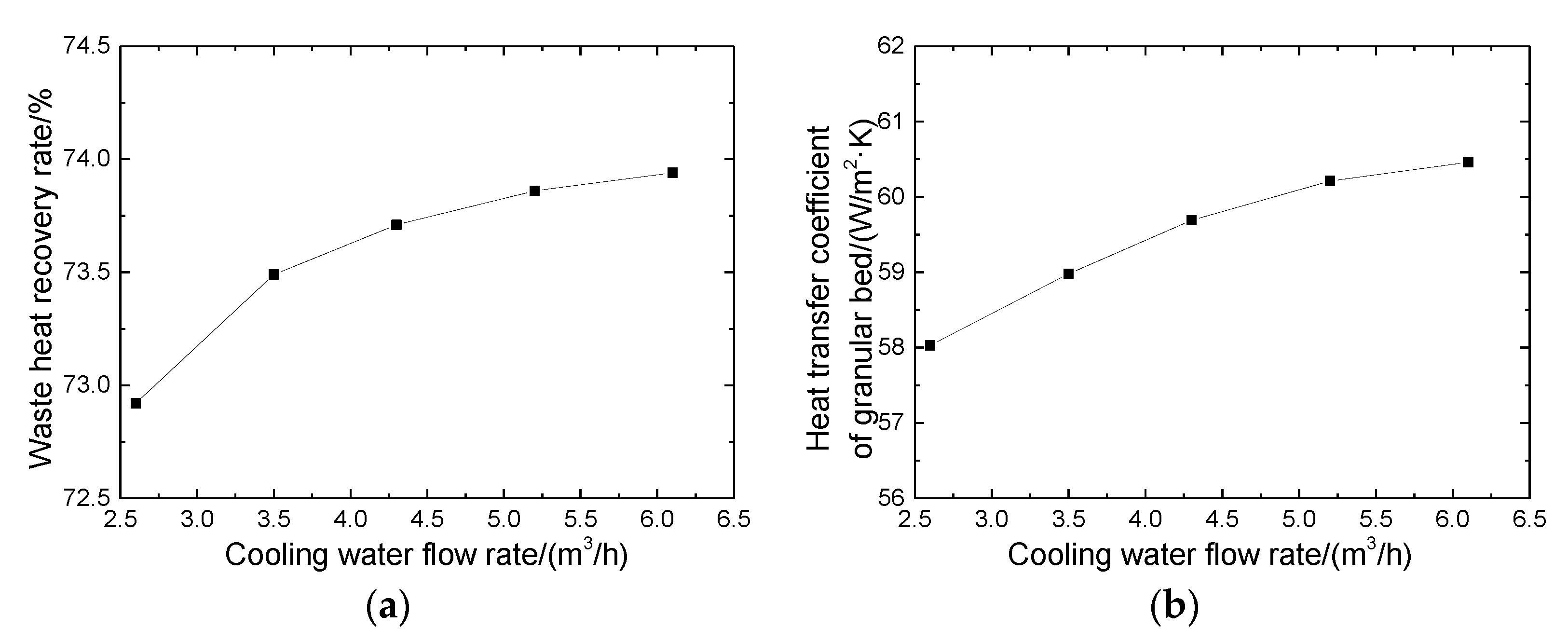
4.3. Influence of Cooling Water Flow on Waste Heat Recovery

After the stable operation of the experimental equipment, the cooling water pipeline valve was manually adjusted to change the cooling water flow rate. The flue gas inlet temperature was 1093.15 K and the flue gas flow was 350 Nm3/h. The initial cooling water flow rate was 2.6 m3/h. The influence curve of the waste heat recovery rate is exhibited in Figure 5.
The experimental results showed that the recovery of waste heat and the heat transfer coefficient of the granular bed increased with the cooling water flow rate. The cooling water flow increased from 2.6 m3/h to 5.1 m3/h, and the waste heat recovery rate of the equipment increased by 1.9% with the increase in the heat transfer coefficient of the granular bed by 4.4%. The increase in the cooling water flow rate promoted the convection between the cooling water inside the heat exchange tube and the tube wall. Thus, the total heat transfer coefficient of the granular bed and heat transfer process was promoted. In accordance with the experimental data displayed in Figure 5b, the changing curve of the heat transfer coefficient of the granular bed was fitted, and the experimental correlation formula was obtained as follows:
k h t = 36.69 7974.34 e 2 q + 10.78 + 60.92 .

5. Numerical Simulation and Analysis

The CFD method was adopted to build a grid model using the Integrated Computer Engineering and Manufacturing (ICEM), and the grid was imported into Fluent for related settings. The granular layer was handled as a porous medium. At present, the equivalent heat transfer coefficient of porous media is generally calculated by the macroscopic induction method to study the heat transfer process of porous media. The Nikitin equation considering the influence of solid particle contact thermal resistance, gas thermal conductivity, and radiation heat transfer was used in this paper. The Nikitin equation is expressed as follows:
k e = k g [ 1 + 3.91 ( 1 φ ) k g 0.1 l n k s k g ] [ 1 + 7 ρ g ρ s + ρ g ( L d ) 0.55 ] 1 + 3.46 σ T 3 [ 3 φ ξ g + ( 1 φ ) ξ s ] 1 + ( 1 φ ) ( 1 ξ s ) + k c
The fluent porous medium model was used to conduct the simulation, with the relevant parameters listed in Table 1. The hydraulic diameter and turbulence intensity were determined by the size of tubes in the bed. The viscous resistance coefficient and the inertial resistance coefficient of porous media were determined by Ergun equation. The thermal conductivity of porous media was determined by the Nikitin equation, with the relevant parameters listed in Table 1.
To verify the grid independence, three grid sizes in the same simulation conditions were set up in this work. The inlet gas temperature was 800 K and the velocity was 1.5 m/s. The cooling water inlet temperature was 300 K and the total flow rate was 0.86 m3/s. The grid independence verification is shown in Table 2. The errors of the three grid sizes were less than 3%, which indicated that the grid independence was verified.
To analyze the temperature distribution in the granular bed intuitively, three planes were taken in the radial and vertical directions of the particle bed, as presented in Figure 6.

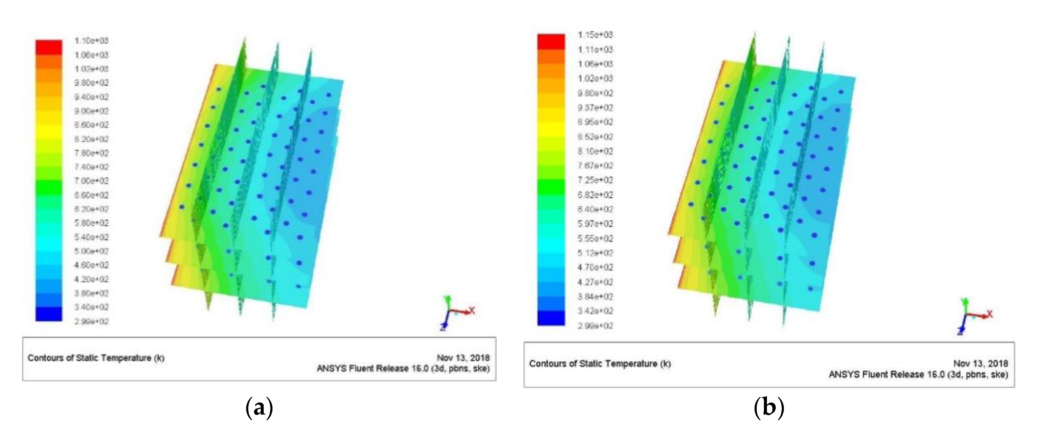
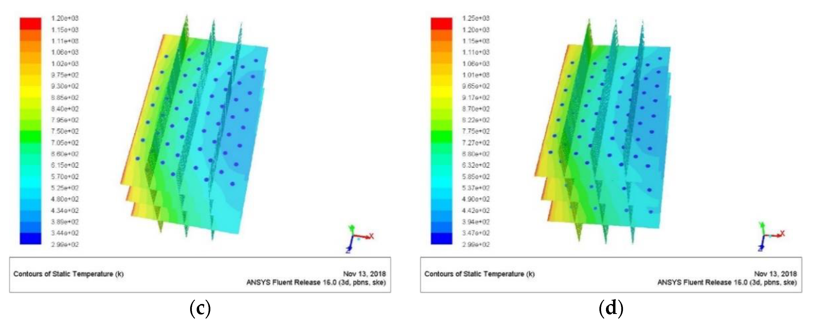
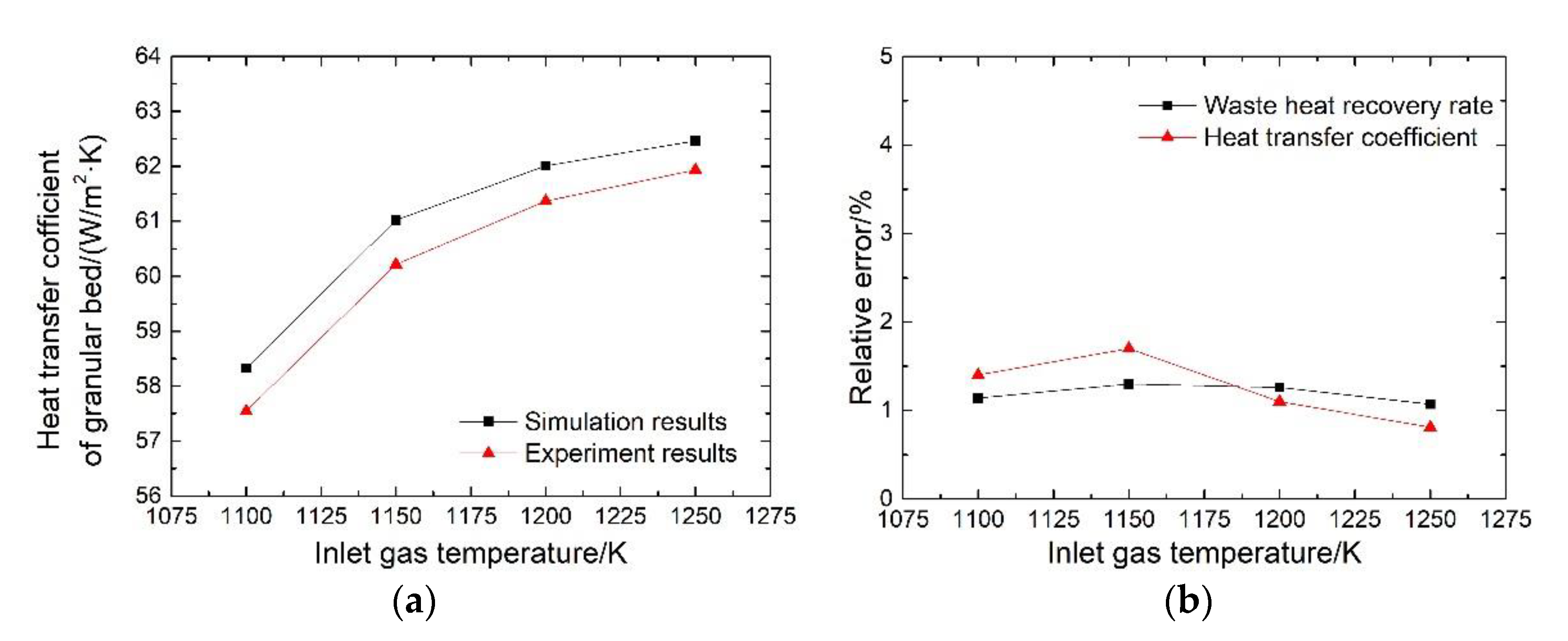
5.1. Heat Transfer under Different Inlet Flue Gas Temperatures

The inlet flue gas temperatures were adjusted and other experimental conditions were provided as follows: The inlet flue gas velocity was 1.5 m/s; the cooling water flow rate in a single heat exchange tube was 0.025 m/s, that is, the overall cooling water flow rate was 4.3 m3/h; and the inlet water temperature was 300 K. The simulation results of the temperature distribution in the granular bed are illustrated in Figure 7. The heat transfer coefficient and waste heat recovery rate of the granular bed heat exchanger with changes in inlet flue gas temperature were calculated using Tecplot, as depicted in Figure 8. The flue gas brought more heat into the bed, and the total heat transfer coefficient and the waste heat recovery rate of the bed increased to different degrees with the increase in the inlet flue gas temperature. The increasing trend slowed down with the rise in the inlet flue gas temperature, and the heat transfer process in the bed remained stable after reaching the critical value.
To analyze the difference between the experimental and simulation results, the effect of flue gas temperature on the heat transfer coefficient of the granular bed was studied. The temperatures of the inlet flue gas were 1100, 1150, 1200, and 1250 K and the speed of inlet flue gas was 1.5 m/s. The flow rate of the cooling water was 4.3 m3/h and the temperature of the inlet cooling water was 300 K. The comparison curves between the experimental and simulated results of the granular bed heat transfer change with the inlet flue gas temperature are plotted in Figure 9.
The relative errors of the heat transfer coefficient and the waste heat recovery were less than 2%, thereby indicating that the simulation and experimental results were reasonable.

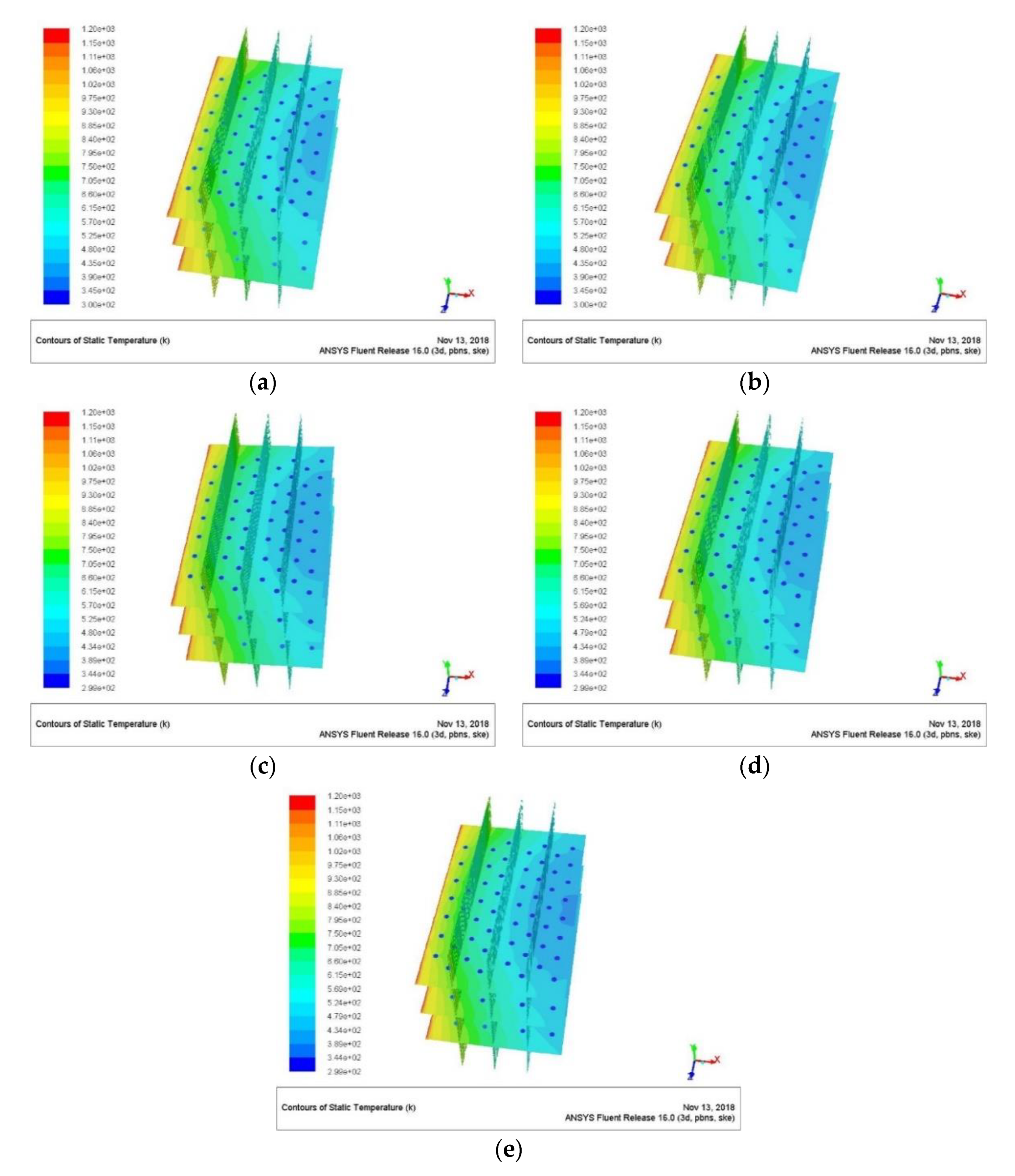
5.2. Heat Transfer under Different Cooling Water Flow Rates

The cooling water flow rate was adjusted and the other experimental conditions were presented as follows: The inlet flue gas temperature was 1200 K, the inlet flue gas velocity was 1.5 m/s, and the inlet cooling water temperature was 300 K. The simulation results are demonstrated in Figure 10.
The heat transfer coefficient and waste heat recovery rate of the granular bed heat exchanger with changes in inlet flue gas temperature were calculated using Tecplot, as exhibited in Figure 11. The increase in the cooling water flow rate slightly promoted the heat transfer in the bed, and the increasing trend slowed down with the rise in the cooling water flow rate. After reaching the critical value, the heat transfer process in the bed remained stable.

6. Conclusions

A buried tube granular bed with 3–5-mm hollow corundum balls as filler particles was developed to reduce heat storage. The experiment was performed at 1073.15 K, and the main conclusions are presented as follows:
(1)
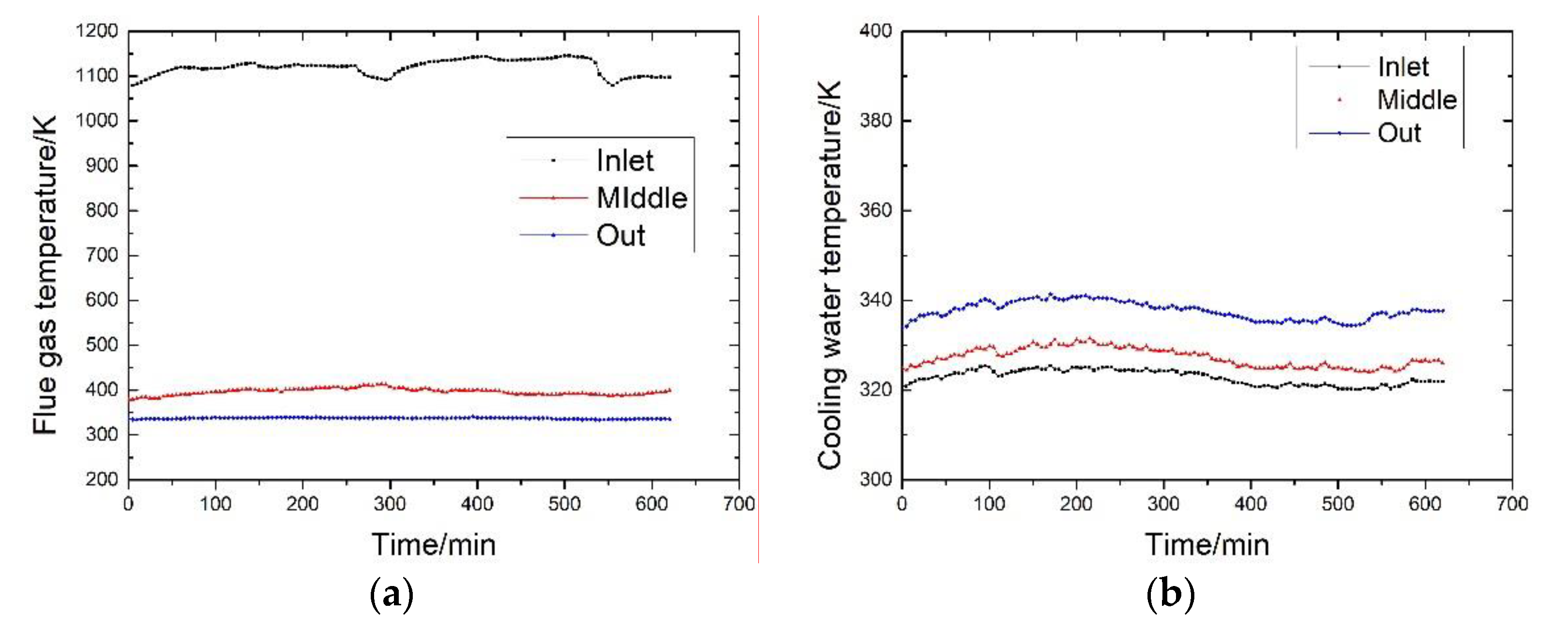
The experimental equipment operated stably at 1073.15 K. The waste heat recovery rate increased gradually when the heat and the recovery rate stored in the particles stabilized at higher than 72% after storage.
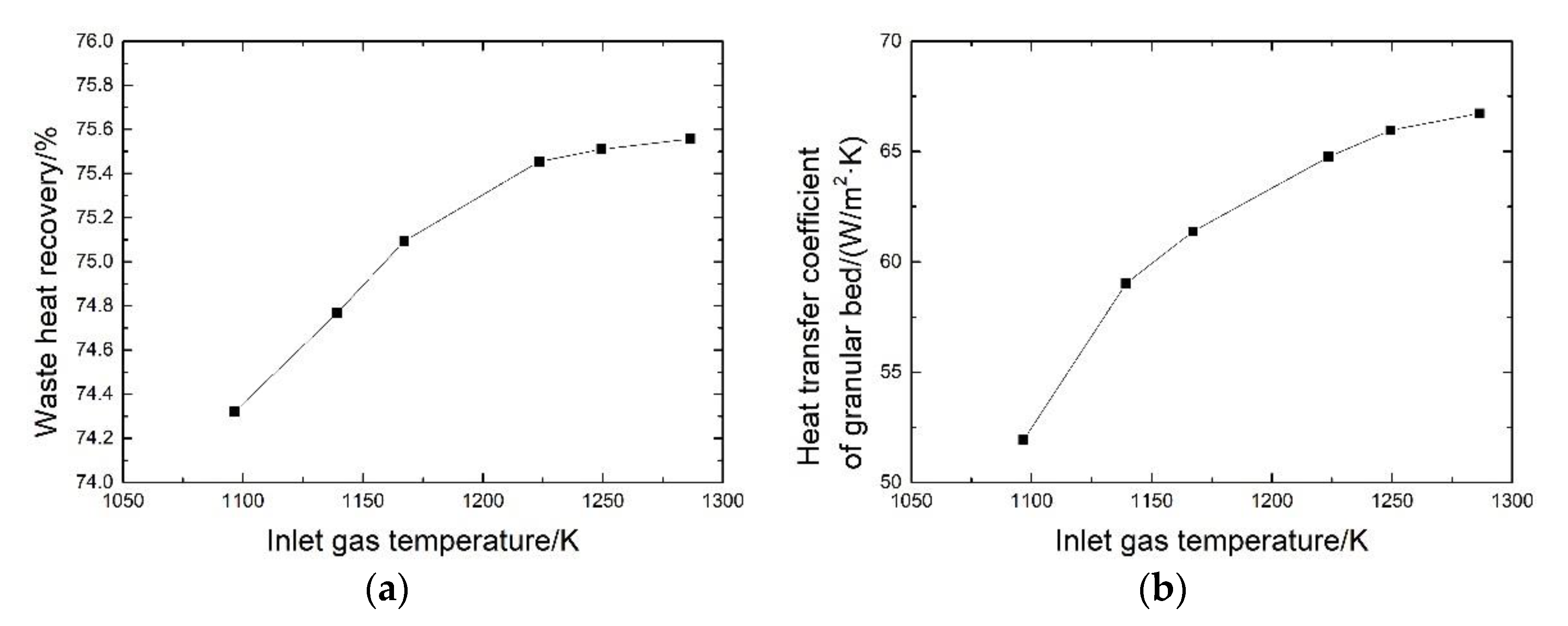
(2)
The waste heat recovery rate of the equipment increased by 1.7%, and the heat transfer coefficient of the granular bed increased by 26.6% with the variation in the inlet gas temperature from 1096.65 K to 1286.45 K. The experimental correlation of the heat transfer coefficient of the granular bed with the inlet gas temperature was proposed.
(3)
The waste heat recovery rate of the equipment increased by 1.9%, and the heat transfer coefficient of the granular bed increased by 4.4% with the variation in the cooling water flow rate from 2.6 m3/h to 5.1 m3/h. The experimental correlation of the heat transfer coefficient of the granular bed with the cooling water flow rate was proposed. With the increase of cooling water flow rate and flue gas inlet temperature, the increase rate of waste heat recovery rate and heat transfer coefficient of granular bed slowed down.
(4)
The heat transfer in the granular bed was simulated. The influence of gas temperature on the heat transfer in the granular bed was studied, and the relative error between the experimental and simulation results was less than 2%.

Author Contributions

F.X. and S.Y. designed the manuscript; S.Y. and F.X. drafted the manuscript; F.X., X.W., and L.T. collected the data and revised the manuscript; L.W. and Y.D. checked the content and revised the manuscript. All authors made contributions to the study and the writing of the manuscript. All authors have read and agreed to the published version of the manuscript.

Funding

The authors gratefully acknowledge the financial support from the National key research and development plan of China (No. 2018YFB0605901).

Conflicts of Interest

The authors declare no conflict of interest.

Nomenclature

NameSignificance
h h t Total heat transfer coefficient of the granular bed, W/(m2·K)
A h t Total heat transfer area, m2
Δ T Logarithmic mean temperature difference, K
cSpecific heat capacity of cooling water, J/(kg·K)
m ˙ Cooling water mass flow rate, kg/s
t w , i n Temperature of inlet cooling water, K
t w , o u t Temperature of outlet cooling water, K
t g , i n Inlet gas temperature, K
t g , o u t Outlet gas temperature, K
nNumber of heat exchange tubes in the granular bed
dDiameter of heat exchange tubes, m
lLength of a single heat exchange tube, m
mTotal mass of the filled particles in the granular bed, kg
m 1 Mass of a single filled particle, kg
rRadius of a single filled particle, m
σBlackbody radiation constant, W/(m2·K4)
k c Contact thermal resistance between particles, m2·K/W
ξ g Gas blackness in porous media
ρ s Density of particles, kg/m3
rRadius of a single filled particle, m

References

  1. Nasr, K.; Ramadhyani, S.; Viskanta, R. An Experimental Investigation on Forced Convection Heat Transfer from a Cylinder Embedded in a Packed Bed. J. Heat Transf. 1994, 116, 73–80. [Google Scholar] [CrossRef]
  2. Pivem, A.C.; Marcelo, J.S. Laminar Heat Transfer in a Moving Porous Bed Reactor Simulated with a Macroscopic Two-energy Equation Model. Int. J. Heat Mass Transf. 2012, 55, 1922–1930. [Google Scholar] [CrossRef]
  3. Zumbrunnen, D.A.; Viskanta, R.; Incropera, F.P. Heat transfer through granular beds at high temperature. Wärme-und Stoffübertrag. 1984, 18, 221–226. [Google Scholar] [CrossRef]
  4. Dayal, R.; Gambaryan-Roisman, T. A novel numerical method for radiation exchange in granular medium. Heat Mass Transf. 2016, 52, 2587–2591. [Google Scholar] [CrossRef]
  5. Shen, C.; Yang, S.L.; Zhang, D.W.; Yu, P.; Yang, J.Z. Experimental Research on Heat Transfer Performance of Parallel Flow Heat Pipe Exchanges. J. Eng. Thermophys. 2018, 39, 1339–1343. [Google Scholar]
  6. Zhang, Z.F.; Ma, T.Z.; Zhao, J.Q.; Huo, X.H. Studies on Heat Transfer from a Vertical Immersed Tube in a Large Particle Fluidized Bed. J. Eng. Thermophys. 1988, 9, 156–160. [Google Scholar]
  7. Royston, D. Heat transfer in the flow of solids in gas suspensions through a packed bed. Ind. Eng. Chem. Process. Des. Dev. 1971, 10, 145–150. [Google Scholar] [CrossRef]
  8. Doherty, J.A.; Verma, R.S.; Shrivastava, S. Heat transfer from immersed horizontal tubes of different diameter in a gas-fluidized bed. Energy 1986, 11, 773–783. [Google Scholar] [CrossRef]
  9. Zhang, S.C.; Wang, Z.F. Experimental and Numerical Investigations on the Fluidized Heat Absorption inside Quartz Glass and Metal Tubes. Energies 2019, 12, 806. [Google Scholar] [CrossRef] [Green Version]
  10. Cong, T.N.; He, Y.R.; Chen, H.S.; Ding, Y.L.; Wen, D.S. Heat transfer of gas-solid two-phase mixtures flowing through a packed bed under constant wall heat. Chem. Eng. J. 2007, 130, 1–10. [Google Scholar] [CrossRef]
  11. Grewal, N.S.; Saxena, S.C. Maximum heat transfer coefficient between a horizontal tube and a gas-solid fluidized bed. Ind. Eng. Chem. Process. Des. Dev. 1981, 20, 108–116. [Google Scholar] [CrossRef]
  12. Yin, S.W.; Li, J.; Shi, G.S.; Xue, F.Y.; Wang, L. Experiment Study on Heat Transfer Characteristics of Dusty Gas Flowing through a Granular Bed with Buried Tubes. Appl. Therm. Eng. 2019, 146, 296–404. [Google Scholar] [CrossRef]
  13. Chen, J.L.; Li, X.F.; Huai, X.L.; Wang, Y.W.; Zhou, J.Z. Numerical Study of Collection Efficiency and Heat-Transfer Characteristics of Packed Granular Filter. Particuology 2019, 46, 75–82. [Google Scholar] [CrossRef]
  14. Yin, S.W.; Shi, Y.L.; Tong, L.G.; Wang, L.; Ding, Y.L. Performance Simulation and Benefit Analysis of Ammonia Absorption Cooling and Heating Dual-Supply System Based on Off-Peak Electricity Heat Storage. Energies 2019, 12, 2298. [Google Scholar] [CrossRef] [Green Version]
  15. Yin, S.W.; Xue, F.Y.; Wang, X.; Wang, L.; Tong, L.G. Experimental Study on Purification and Waste Heat Recovery Characteristics of Dusty Gas in Buried Tube Granular Bed. J. Eng. Thermophys. 2019, 40, 1928–1935. [Google Scholar]
  16. Wang, N.H.; Meng, F.Z. Influence of Logarithmic Mean Temperature Difference on Heat Transfer Area of Heat Exchanges. Petro-Chem. Equip. 1999, 28, 13–15. [Google Scholar]
Figure 1. Schematic of the experimental flow and location of measuring points.
Energies 13 03589 g001
Figure 2. Schematic of the arrangement of heat exchange tubes.
Energies 13 03589 g002
Figure 3. Variation curves of heat exchange in the buried tube granular bed. (a) Variation curve of flue gas temperature. (b) Variation curve of cooling water temperature. (c) Variation curve of waste heat recovery rate. (d) Variation curve of bed pressure drop.
Energies 13 03589 g003aEnergies 13 03589 g003b
Figure 4. Influence curves of flue gas temperature on heat transfer. (a) Influence on waste heat recovery. (b) Influence on the heat transfer coefficient.
Energies 13 03589 g004
Figure 5. Influence curves of cooling water flow on waste heat recovery. (a) Influence on the recovery rate of waste heat. (b) Influence on the heat transfer coefficient.
Energies 13 03589 g005
Figure 6. Schematic of the section position of the granular bed.
Energies 13 03589 g006
Figure 7. Temperature distribution under different inlet flue gas temperatures in granular bed. (a) Inlet flue gas temperature was 1100 K. (b) Inlet flue gas temperature was 1150 K. (c) Inlet flue gas temperature was 1200 K. (d) Inlet flue gas temperature was 1250 K
Energies 13 03589 g007aEnergies 13 03589 g007b
Figure 8. Influence of flue gas temperature on the heat transfer in granular bed. (a) Influence on the waste heat recovery rate. (b) Influence on the heat transfer coefficient.
Energies 13 03589 g008
Figure 9. Comparison of experimental and simulation results. (a) The influence of gas temperature on the coefficient. (b) Variation curve of relative error.
Energies 13 03589 g009
Figure 10. Temperature distribution under different cooling water flow rates. (a). Cooling water flow rate was 2.6 m3/h. (b) Cooling water flow rate was 3.5 m3/h. (c) Cooling water flow rate was 4.3 m3/h. (d) Cooling water flow rate was 5.2 m3/h. (e) Cooling water flow rate was 6.1 m3/h.
Energies 13 03589 g010
Figure 11. Influence of cooling water flow rate on the heat transfer in granular bed. (a) Influence on the waste heat recovery rate. (b) Influence on the heat transfer coefficient.
Energies 13 03589 g011
Table 1. Fluent simulation parameter setting.
Parameter/UnitValue
Hydraulic diameter/mm16
Turbulence intensity/%13
Material equivalent diameter/mm5
Viscous resistance coefficient of porous media4551.54
Inertial resistance coefficient of porous media18,148.15
Thermal conductivity of porous media/W/(m2·K)39.59
Table 2. Grid independence verification.
Grid SizesInlet Gas Temperature/KOutlet Gas Temperature/KRelative Error/%
80,342800665.32
2,764,566800664.211.67
4,537,529800663.832.25

