Article

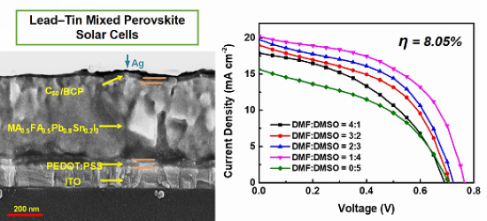
Co-Solvent Controllable Engineering of MA0.5FA0.5Pb0.8Sn0.2I3 Lead–Tin Mixed Perovskites for Inverted Perovskite Solar Cells with Improved Stability

Department of Electro-Optical Engineering, National Taipei University of Technology, Taipei 10608, Taiwan
*
Author to whom correspondence should be addressed.
Energies 2020, 13(10), 2438; https://doi.org/10.3390/en13102438
Submission received: 14 April 2020 / Revised: 10 May 2020 / Accepted: 11 May 2020 / Published: 13 May 2020
(This article belongs to the Special Issue Perovskite Solar Cells)

Abstract

:
Use of a lead–tin mixed perovskite is generally considered an effective method to broaden the absorption wavelength of perovskite thin films. However, the preparation of lead–tin mixed perovskites is a major challenge due to the multivalent state of tin and stability in the atmosphere. This study attempted to replace the organic cation and metal elements of perovskites with a relatively thermal stable formamidinium (FA+) and a more environmentally friendly tin element. MA0.5FA0.5Pb0.8Sn0.2I3 lead–tin mixed perovskite thin films were prepared with the one-step spin-coating method. By adjusting the dimethylformamide (DMF):dimethyl sulfoxide (DMSO) concentration ratio of the lead–tin mixed perovskite precursor solution, the surface morphologies, crystallinity, and light-absorbing properties of the films were changed during synthesis to optimize the lead–tin mixed perovskite films as a light-absorbing layer of the inverted perovskite solar cells. The quality of the prepared lead–tin mixed perovskite film was the highest when the ratio of DMF:DMSO = 1:4. The power-conversion efficiency of the perovskite solar cell prepared with the film was 8.05%.

Graphical Abstract

1. Introduction

Hybrid organic–inorganic perovskites ABX3 (A = MA+ (CH3NH3), FA+ (CH(NH2)2); B = Pb, Sn; X = I, Br, Cl) have attracted considerable attention as promising semiconductor materials due to their excellent photovoltaic properties [1,2,3]. High optical absorption coefficients, long carrier diffusion lengths, easy preparation, low cost, and high efficiency are the advantages of hybrid organic–inorganic perovskite materials. In order to achieve high power-conversion efficiency (PCE) in perovskite solar cells, scholars from various circles have made considerable efforts to improve the device structure and optimize the perovskite layer [4,5,6]. In the last few years, the power-conversion efficiency of organic–inorganic hybrid perovskites has increased from 3.81% to 25.2% [7,8,9,10]. However, to realize the industrial application of perovskite solar cells, there are still many problems, such as the research and development of non-toxic materials. The metal Pb element in current high-efficiency perovskite solar-cell light-absorbing materials is one of the chemicals that seriously endanger human life and the natural environment. Pb-based perovskite solar cells have poor thermal stability and chemical stability, and metal Pb in the film is easily released, polluting the environment [11,12,13]. Therefore, another feature of perovskite material is that it can easily regulate the constituent elements of the material, which is very conducive to using non-toxic or low-toxic elements to replace metal Pb for environmentally friendly purposes.
An appropriate optical band gap and absorption wavelength are important for perovskite light-absorbing materials, which not only restrict the photon-utilization efficiency of perovskite materials but also determine whether a material can be applied to solar cells. The adjustment of perovskite composition gives the material more variability and wide applications. Ion hybrid systems have become an important principle in the structural design of perovskite solar cells. In order to obtain high-efficiency lead-free or low-lead perovskite solar cells, in addition to controlling the band gap of the perovskite material by adjusting the proportion of halogen atoms, the band gap can also be effectively controlled by adjusting the proportion of metal ions. Research on lead-free perovskite solar cells has increased in recent years, and many studies have found alternative elements to lead, such as tin (Sn), germanium (Ge), and copper (Cu). Sn has been proven to completely or partially replace metal Pb in perovskite solar cells [14,15,16,17]. The absorption spectrum of Sn-based perovskite materials has a significant red shift compared to Pb-based perovskite materials. The absorption cut-off wavelength was extended from 800 to about 950 nm, and the optical band gap was reduced from 1.45 to about 1.21 eV. The reason for this phenomenon is that the size of the optical band gap mainly depends on the lattice constant of the material. Due to the different atomic radii of Sn2+ and Pb2+, lattice parameters differ greatly, and the optical band gap also changes accordingly, causing the absorption spectrum to be a red-shift phenomenon [18]. When Pb is replaced by Sn, the triplet of Sn-based perovskite is reduced by spin-orbit coupling under the excitation of sunlight, which is beneficial to reduce the recombination of electron-hole pairs, thereby increasing the photocurrent in perovskite solar cells [19]. In addition to the lattice parameters, process parameters also have a great impact on the absorption properties of perovskite materials. Excessive heat-treatment temperature leads to the decomposition of the perovskite material and ultimately affects its light-absorption performance [20].
At present, the maximal PCE of Sn-based perovskite devices has reached 9% [14], far ahead of other lead-free materials (Ge, Bi, Sb, Cu, etc.), but at the same time, far behind Pb-based analogs that have a 25.2% PCE [10]. The main problem of replacing Pb with Sn is that it is unstable in terms of a chemical low-valence state (Sn4+ is more stable than Sn2+), and doping metal Pb to inhibit the oxidation of Sn2+ to Sn4+ can effectively improve stability [21] and change the band gap of hybrid perovskite materials [15]. Zhu et al. [15] optimized the structure of the device by simply adjusting the proportion of dimethyl sulfoxide (DMSO) in the mixed solvent, increasing the PCE of the MAPb0.75Sn0.25I3 perovskite solar cell to 15.2%. When Cs was incorporated into the perovskite film [22], the PCE of the prepared FA0.8Cs0.2Pb0.75Sn0.25I3 and MA0.9Cs0.1Pb0.75Sn0.25I3 cells could be improved to 14.5–14.6%. However, there was a problem because the reaction between SnI2 and MAI (CH3NH3I) is faster than with PbI2, which makes the morphology of the material more difficult to control [23]. Moreover, it has a high solubility in polar solvents such as isopropanol, which makes the preparation of the two-step solution method more difficult [24]. Since the perovskite precursor uses different solvents to have a great influence on the morphology and crystallinity of the film formed, the morphology and crystallinity of the perovskite film is the key to restrict the separation and transmission of photo-generated carriers in perovskite materials.
In order to improve the photovoltaic performance of the device, this study introduces a controlled ratio of a mixed dimethylformamide (DMF)/DMSO solvent, and an FA+ cation was used to replace part of the MA+ cation to prepare MA0.5FA0.5Pb0.8Sn0.2I3 lead–tin mixed perovskites, combined with the corresponding characterization to further study the effect of solvent on the film formation, crystallinity, and microstructure control of lead–tin mixed perovskites. In this work, we also employed different starting materials, FAI and SnF2, except for MAI, PbI2, DMF, DMSO, and toluene. The SnF2 is used to suppress the oxidation of Sn.

2. Materials and Methods

2.1. Materials

MAI (99.999%) and FAI ((CH(NH2)2)I) (99.999%) were purchased from Lumtec Co. PbI2 (99.999%) and SnI2 (99.999%) were purchased from Alfa Aesar. DMF, DMSO, and toluene (99.99%) were purchased from Echo Chemical. Tin(II) fluoride (SnF2) (99%), PEDOT:PSS (Heraeus® Clevios™ P VP Al 4083), C60 (Fullerene) (99.9%), and 2,9-dimethyl-4,7-diphenyl-1,10-phenanthroline (BCP) (96%) were purchased from Uni-Onward. Indium tin oxide (ITO)-coated glass (substrate, sheet resistance 7 Ω sq−1) was purchased from Ruilong.

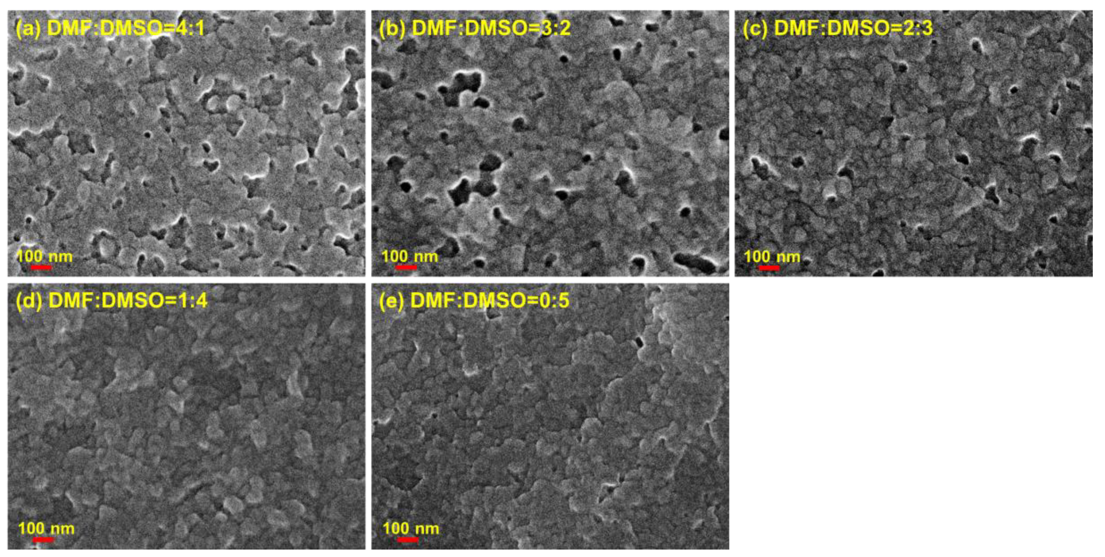
2.2. Fabrication of MA0.5FA0.5Pb0.8Sn0.2I3 Lead–Tin Mixed Perovskite Films

To prepare the MA0.5FA0.5Pb0.8Sn0.2I3 lead–tin mixed perovskite precursor solutions, MAI (0.7 M), FAI (0.7 M), PbI2 (1.12 M), SnI2 (0.28 M), and 10 mol % of SnF2 were dissolved in 1 mL of DMF/DMSO mixed solvent. Among them, the use of SnF2 relieves the Sn oxidation, improving the material stability and film formation quality [25,26]. Excessive SnF2 will cause phase separation on the surface of the perovskite film, thereby reducing device performance [27]. We maintained the same concentration of substances, merely changing the solvent ratio of DMF and DMSO. The DMF/DMSO mixed solvent ratios in this study were 4:1, 3:2, 2:3, 1:4, and 0:5, respectively. Finally, the precursor solution was stirred at 80 °C for more than 1 h in a glove box to obtain a perovskite precursor solution with a concentration of 1.4 molar. The 70 μL MA0.5FA0.5Pb0.8Sn0.2I3 lead–tin mixed perovskite active layer was deposited by two-step continuous spin coating at 1000 and 5000 rpm for 10 and 40 s, respectively. Then, 300 μL of toluene was slowly dripped in situ onto the substrate when the second stage had 20 s remaining, and then annealed at 100 °C for 10 min.
Figure 1 shows the photographs of lead–tin mixed perovskite films with different DMF/DMSO mixed solvent ratios. During film formation, as the amount of DMSO in the mixed solvent increased, the MA0.5FA0.5Pb0.8Sn0.2I3 lead–tin mixed perovskite film gradually changed from black to brown. By reducing the amount of DMSO in the mixed solvent, the reaction from the precursors to the perovskites was faster due to the weaker bonding capacity and greater volatility of DMF. Results showed that, in the case of DMF/DMSO = 4:1, the film became black. DMSO could, therefore, be used to control the crystallization of MA0.5FA0.5Pb0.8Sn0.2I3 perovskites to determine film formation.

2.3. Fabrication of Perovskite Solar Cells

The ITO-coated glass substrates were washed ultrasonically in acetone, ethanol, and isopropanol for 20 min each, sequentially, with ultraviolet–ozone treatment for 15 min to improve the hydrophilicity of the ITO-coated glass substrates. The PEDOT:PSS solution was spin-coated on the cleaned ITO-coated glass as the hole transport layer at 5000 rpm for 30 s, and then annealed at 120 °C for 10 min under ambient conditions. Afterward, the perovskite precursor solutions of MA0.5FA0.5Pb0.8Sn0.2I3 with different DMF/DMSO mixed solvent ratios (4:1, 3:2, 2:3, 1:4, and 0:5) were deposited on the PEDOT:PSS layer-coated ITO substrates, respectively. All of these preparations were done in a glove box. A 20-nm-thick C60 electron-transporter layer and 8-nm-thick BCP were sequentially deposited by thermal evaporation. Finally, a 100 nm-thick Ag electrode was deposited at a rate of 0.2 to 0.3 nm/s under a vacuum pressure of 4.8 × 10⁻⁵ torr. The BCP was used as a buffer layer for the Ag contact. Afterward, all devices were encapsulated in an N2-filled glove box by sealing the active area to another piece of glass. The MA0.5FA0.5Pb0.8Sn0.2I3 lead–tin mixed perovskite solar-cell configurations and cross-sectional scanning-electron-microscopy (SEM) image could then be completed, as shown in Figure 2. It shows a dense compact perovskite film with a thickness of about 450 nm, which is advantageous for achieving high-performance perovskite solar cells.

2.4. Characterization

The surface morphologies were observed by field-emission SEM (FESEM, ZEISS Sigma, ZEISS, Munich, Germany). X-ray diffraction (XRD) patterns were recorded using an X-ray diffractometer with CuKα (λ = 1.5418 Å) radiation operated at 40 kV and 25 mA (X’Pert PRO MRD, PANalytical, Almelo, The Netherlands). The absorption spectra were measured using a UV/VIS/NIR spectrophotometer (UH-4150, Hitachi, Tokyo, Japan). Photovoltaic current density (J)–voltage (V) measurements under one-sun air mass (AM) 1.5G simulation (1000 mW/cm2 at 25 °C) were used to confirm the contribution of the spectral conversion layers. The solar simulator (XES-151S, San-Ei Electric Co., Ltd., Japan) was calibrated using a crystalline silicon reference cell (PVM-894, PV Measurements Inc., Boulder, CO, USA) certified by the National Renewable Energy Laboratory (NREL) prior to the measurement of lead–tin mixed perovskite solar cell devices. External quantum efficiencies (EQE) were measured using a spectral response measurement system (QE-R3015, Enli Technololy Co. Ltd., Taiwan), and a calibrated Si photodiode with a known spectral response was used as a reference.

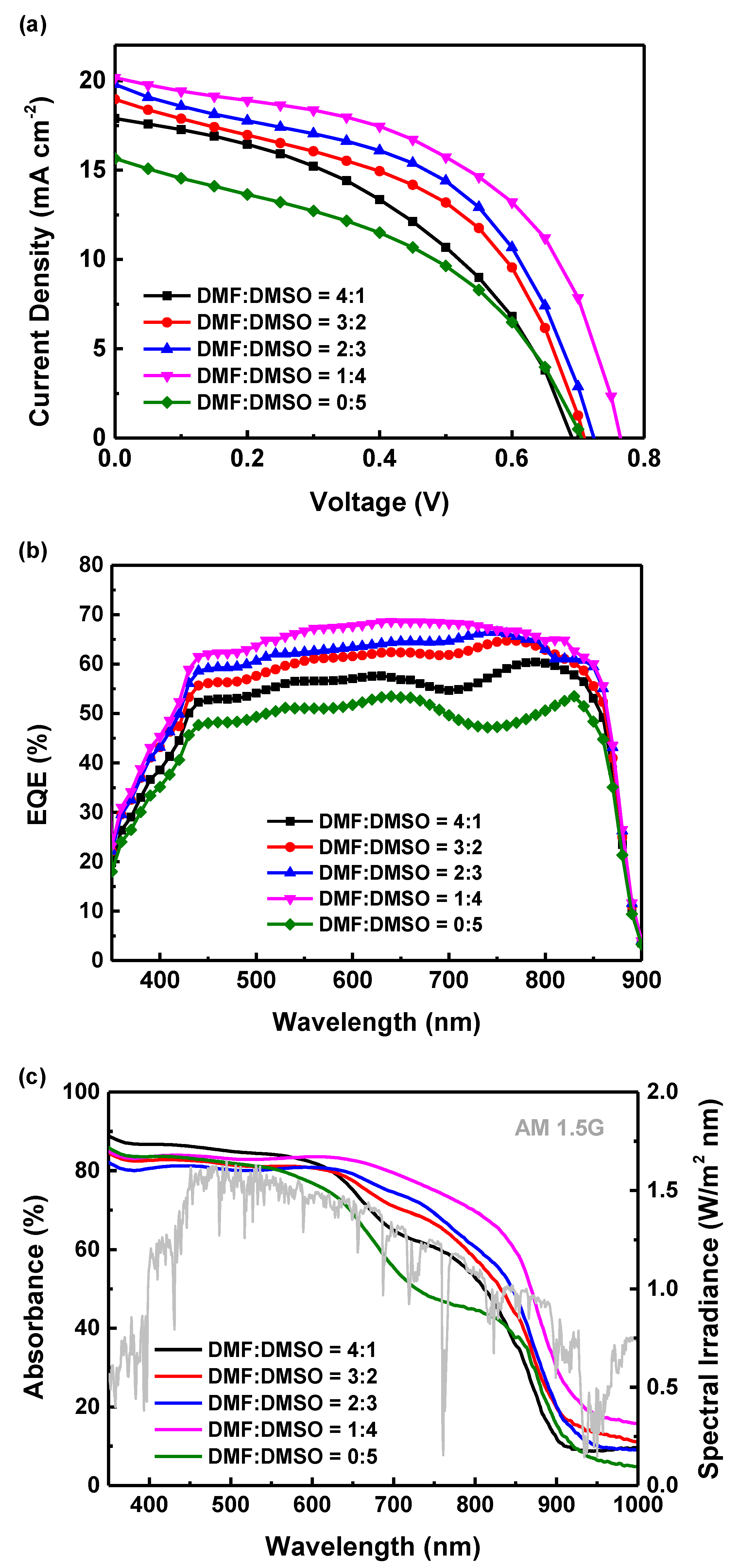
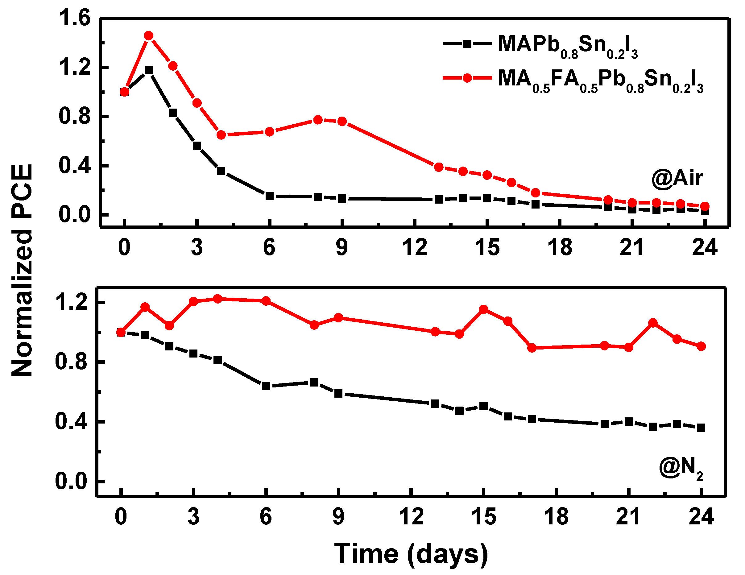
3. Results and Discussion

The top-view SEM images in Figure 3a–e show the morphology differences of the MA0.5FA0.5Pb0.8Sn0.2I3 lead–tin mixed perovskite films based on different DMF/DMSO mixed solvent ratios. All samples showed perovskite crystals with different sizes and coverage areas. Therefore, the amount of DMSO in the solvent determined the quality of the perovskite film. When the amount of DMSO was low, the reaction rate of the precursor solution was fast, which caused the perovskite film to show pores and not be conducive to the superposition of subsequent electron-transport layers (Figure 3a). As the amount of DMSO increased, the reaction rate of the precursor solution was suppressed, and the quality of the perovskite film was improved. Perovskite film quality was best when the ratio of DMF:DMSO = 1:4 (Figure 3d). However, when the amount of DMSO was increased, the reaction of the precursor solution was too slow, which was not conducive for the formation of a dense perovskite film (Figure 3e). Therefore, when the ratio of the solvent DMF:DMSO = 1:4, compared with other morphologies of perovskite films, the grains in the perovskite film were smaller and had fewer grain boundaries. This is because excess DMSO in the solvent dissolved the PbI2 and SnI2 molecular groups in the precursor to a smaller size, resulting in smaller crystal grains during film formation [15,28].
Figure 4 shows the XRD patterns of MA0.5FA0.5Pb0.8Sn0.2I3 lead–tin mixed perovskite films with different DMF/DMSO mixed solvent ratios. Diffraction peaks at 14.01°, 19.84°, 24.37°, 28.23°, 31.62°, 40.35°, and 42.88° were assigned to (110), (112), (202), (220), (114), (224), and (314) of the MA0.5FA0.5Pb0.8Sn0.2I3 perovskites, respectively. These peaks indicated that these films had a similar perovskite structure. When the ratio of the mixed solvent was DMF:DMSO = 1:4, the XRD peaks of the perovskite films on the (110) and (220) crystal planes were stronger and sharper than those of other solvents. This result was consistent with the SEM investigation, which proves that the crystallinity of the perovskite film is better when the solvent ratio is DMF:DMSO = 1:4. On the other hand, when the ratio of the mixed solvent was DMF:DMSO = 0:5, this showed that pure DMSO made the PbI2 reaction incomplete [29], resulting in perovskite crystallinity reduction. In Figure 4, the XRD patterns show that the peak (114) is significantly diminished compared to other peaks when the concentration of DMF increases. The main role of DMSO in a DMF/DMSO mixed solvent is to interact with the precursor to form an intermediate of MAI/FAI-PbI2/SnI2-DMSO, and then to remove the DMSO by thermal annealing to form a perovskite crystal film. The formation of this intermediate can alleviate the reaction rate between PbI2/SnI2 and MAI/FAI and is more conducive to the formation of a dense and uniform perovskite film [30]. MAI/FAI will also replace the position of DMSO and react with SnI2 and PbI2. The DMSO-capped cluster can provide a large number of reaction sites between MAI/FAI and SnI2/PbI2. The relatively slower reaction rate leads to poor perovskite crystallinity and random orientation. Therefore, adding an appropriate amount of DMSO to the precursor solution not only reduces the film-forming reaction rate but also effectively improves the crystallinity of the lead–tin mixed perovskite.
In order to study the energy band in detail, the optical band gap of the lead–tin mixed perovskite film was estimated from the Tauc relation.
( α h v ) 2 = A ( h v E g ) ,
α = ln ( 1 T ) d ,
where α is the absorption coefficient, Eg is the energy band gap, hv is the photon energy, A is a constant, d is the film thickness, and T is the transmittance. Figure 5 describes the variation between the (αhν)2 and photon energy (eV) of MA0.5FA0.5Pb0.8Sn0.2I3 lead–tin mixed perovskite films with different DMF/DMSO mixed solvent ratios. As the DMF/DMSO mixed solvent ratio changes from 4:1 to 0:5, it can be observed that the optical band gap of the perovskite films was significantly red-shifted; the optical band gap decreased from 1.39 eV to 1.37 eV, which was about 0.21–0.23 eV lower than the energy gap of MAPbI3 (~1.6 eV) [31,32]. This result shows that the optical band gap value of this MA0.5FA0.5Pb0.8Sn0.2I3 lead–tin mixed perovskite film was similar to that of a previous report [33]. We confirmed that the lead–tin mixed perovskite film does have the characteristic of reducing the energy gap and widening the absorption wavelength.
The current density–voltage (J–V) characteristics of MA0.5FA0.5Pb0.8Sn0.2I3 lead–tin mixed perovskite solar cells prepared by adjusting the mixed solvent ratio of DMF:DMSO = 4:1, 3:2, 2:3, 1:4, and 0:5 are shown in Figure 6a, and solar-cell parameters are summarized in Table 1. The short-circuit current density (Jsc), open circuit voltage (Voc), fill factor (FF), and PCE of all perovskite solar cells, respectively, first increased with increasing DMSO in the mixed solvent, and then decreased with a further increase in the DMF:DMSO mixed solvent ratio, which reached the maximum at DMF:DMSO = 1:4 mixed solvent. The optimal mixed solvent ratio of DMF:DMSO was 1:4, and the device exhibited a PCE of 8.05% with a Voc of 0.76 V, a Jsc of 20.18 mA cm−2, and an FF of 52.5%. As the DMF/DMSO mixed solvent ratio changes from 4:1 to 1:4, except for the case of DMF:DMSO = 0:5, Voc can be observed to increase significantly, especially under the condition of DMF:DMSO = 1:4; the largest Voc was about 0.76 V, which can be attributed to the better quality and fewer grain boundaries of the lead–tin mixed perovskite film, as substantiated by the previously shown XRD and SEM results. Figure 6b shows the EQE spectra for the MA0.5FA0.5Pb0.8Sn0.2I3 lead–tin mixed perovskite solar cells, where the data show a high EQE value above 50% across a broad wavelength range from 450 to 850 nm, with the photon spectral response extending to around 850 nm. The photocurrent densities integrated from EQE spectra match well with the Jsc obtained in J–V curves measured under a solar simulator, and the variation is within 3%.
UV–Vis absorption spectra of the MA0.5FA0.5Pb0.8Sn0.2I3 lead–tin mixed perovskite films based on DMF/DMSO mixed solvent ratios are shown in Figure 6c. The absorption ranges of all samples fell close to 900 nm, which was about hundreds of nanometers wider compared to the absorption range of MAPbI3 perovskite films in our previous research [34]. As the proportion of DMSO increased, film absorptance decreased to the lowest value in a wavelength range from 400 to 1000 nm, and then rose again. In the infrared-light wavelength range from 800 to 1000 nm, absorptance significantly improved. When the mixed solvent ratio was DMF:DMSO = 1:4, there was better absorptance in this wavelength range. It should be noted that the perovskite film prepared by using DMF:DMSO = 1:4 has more than 10% absorbance at the wavelength over 900 nm. It may be attributed to the localized exciton effect resulting from exciton impurity interaction and usually ascribed to the scattering of incident light due to rough perovskite morphology. To sum up, the experimental result of the material properties of the perovskite film with DMF:DMSO = 1:4 was the best, indicating the optimal ratio of the DMF/DMSO mixed solvents, and perovskite solar cells with DMF:DMSO = 1:4 displayed the best photovoltaic performance.
Figure 7 shows a comparison of the normalized efficiency of MAPb0.8Sn0.2I3 and MA0.5FA0.5Pb0.8Sn0.2I3 perovskite solar cells as a function of storage time under air and nitrogen-filled glove box (H2O and O2 were both controlled to less than 1 ppm) environments. Under the air environment, the efficiency of the MAPb0.8Sn0.2I3 perovskite solar cell decreased rapidly before the fifth day and remained at about 10% of initial efficiency after the fifth day. In addition, the MA0.5FA0.5Pb0.8Sn0.2I3 perovskite solar cell could maintain more than 60% of its original efficiency before the 10th day, and it began to decline after 15 days and approached the efficiency of the MAPb0.8Sn0.2I3 perovskite solar cell. On the other hand, under a nitrogen environment, the efficiency of the MAPb0.8Sn0.2I3 perovskite solar cell continued to decrease with time, and it had dropped below 40% of the initial efficiency on the 24th day. In particular, the MA0.5FA0.5Pb0.8Sn0.2I3 perovskite solar cell still maintained an initial efficiency of more than 80%. We concluded that the lead–tin mixed perovskite solar cells partially replaced by FA+ organic cations were superior to all MA+ organic cation solar cells in maintaining efficiency, which confirmed that FA organic cations have a stable effect on maintaining the efficiency of lead–tin mixed perovskite solar cells [35]. Another factor may also be that under water-free and oxygen-free conditions, which indicated the MA0.5FA0.5Pb0.8Sn0.2I3 perovskite material was essentially stable in a nitrogen environment, no obvious degradation would occur for the MA0.5FA0.5Pb0.8Sn0.2I3 device. For comparison, state-of-the-art research studies of FA1-yMAyPb1-xSnxI3 perovskites solar cell parameters are summarized in Table 2 [36,37,38,39,40]. These works are focused on electron transport layer (ETL) or hole transport layer (HTL) engineering. However, in this work, we focused on the active layer to improve the reliability of devices by using SnF2 and DMF/DMSO as starting materials.

4. Conclusions

In conclusion, FAI and SnF2 were employed as starting materials, except for MAI, PbI2, DMF, DMSO, and toluene. We successfully prepared MA0.5FA0.5Pb0.8Sn0.2I3 lead–tin mixed perovskite films with different surface morphologies and material characteristics by using different ratios of DMF/DMSO mixed solvents. It was proven that when the DMF:DMSO mixed solvent ratio was 1:4, the quality and crystallinity of the perovskite film and the optical properties of the perovskite active layer were the best. In addition, the stability of device efficiency showed that the addition of an FA+ organic cation could improve the efficiency of lead–tin mixed perovskite solar cells in an air or nitrogen environment. The maximal PCE of the best-performing perovskite solar cell based on a DMF:DMSO = 1:4 mixed solvent ratio in this study was 8.05%.

Author Contributions

L.-C.C. carried out the experiments, designed the study, and gave significant suggestions for writing the manuscript. C.-H.T. conceived the original idea, performed data analysis and interpretation, and wrote the manuscript. Y.-C.J. and W.-C.L. prepared the samples and performed all measurements. All authors have read and agreed to the published version of the manuscript.

Funding

This research was funded by MOST Nos. 108-2221-E-027-093 and 109-2218-E-027-003-MY2.

Acknowledgments

This work was supported by the Ministry of Science and Technology (Taiwan) under contract nos. 108-2221-E-027-093 and 109-2218-E-027-003-MY2.

Conflicts of Interest

The authors declare no conflict of interest.

References

  1. Hou, Y.; Du, X.; Scheiner, S.; McMeekin, D.P.; Wang, Z.; Li, N.; Killian, M.S.; Chen, H.; Richter, M.; Levchuk, I.; et al. A generic interface to reduce the efficiency-stability-cost gap of perovskite solar cells. Science 2017, 358, 1192–1197. [Google Scholar] [CrossRef] [PubMed] [Green Version]
  2. Chen, L.C.; Tien, C.H.; Tseng, Z.L.; Ruan, J.H. Enhance efficiency of MAPbI3 perovskite solar cells with FAPbX3 perovskite quantum dots. Nanomaterials 2019, 9, 121. [Google Scholar] [CrossRef] [PubMed] [Green Version]
  3. Wu, Y.; Xie, F.; Chen, H.; Yang, X.; Su, H.; Cai, M.; Zhou, Z.; Noda, T.; Han, L. Thermally stable MAPbI3 perovskite solar cells with efficiency of 19.19% and area over 1 cm2 achieved by additive engineering. Adv. Mater. 2017, 29, 1701073. [Google Scholar] [CrossRef] [PubMed]
  4. Xie, F.; Chen, C.C.; Wu, Y.; Li, X.; Cai, M.; Liu, X.; Yang, X.; Han, L. Vertical recrystallization for highly efficient and stable formamidinium-based inverted-structure perovskite solar cells. Energy Environ. Sci. 2017, 10, 1942–1949. [Google Scholar] [CrossRef]
  5. Chiang, C.H.; Wu, C.G. Bulk heterojunction perovskite–PCBM solar cells with high fill factor. Nat. Photonics 2016, 10, 196–200. [Google Scholar] [CrossRef]
  6. Ye, F.; Yang, W.; Luo, D.; Zhu, R.; Gong, Q. Applications of cesium in the perovskite solar cells. J. Semicond. 2017, 38, 011003. [Google Scholar] [CrossRef]
  7. Fu, F.; Pisoni, S.; Weiss, T.P.; Feurer, T.; Wackerlin, A.; Fuchs, P.; Nishiwaki, S.; Zortea, L.; Tiwari, A.N.; Buecheler, S. Compositionally graded absorber for efficient and stable near-infrared-transparent perovskite solar cells. Adv. Sci. 2018, 5, 1700675. [Google Scholar] [CrossRef] [Green Version]
  8. Zhang, H.; Cheng, J.; Li, D.; Lin, F.; Mao, J.; Liang, C.; Jen, A.K.; Grätzel, M.; Choy, W.C. Toward all room-temperature, solution-processed, high-performance planar perovskite solar cells: A new scheme of pyridine-promoted perovskite formation. Adv. Mater. 2017, 29, 1604695. [Google Scholar] [CrossRef]
  9. Qin, X.; Zhao, Z.; Wang, Y.; Wu, J.; Jiang, Q.; You, J. Recent progress in stability of perovskite solar cells. J. Semicond. 2017, 38, 011002. [Google Scholar] [CrossRef]
  10. Best Research-Cell Efficiencies, National Renewable Energy Laboratory. Available online: https://www.nrel.gov/pv/assets/pdfs/best-research-cell-efficiencies.20200128.pdf (accessed on 27 January 2020).
  11. Wang, Z.; Shi, Z.; Li, T.; Chen, Y.; Huang, W. Stability of perovskite solar cells: A prospective on the substitution of the A cation and X anion. Angew. Chem. Int. Ed. 2017, 56, 1190–1212. [Google Scholar] [CrossRef]
  12. Li, B.; Li, Y.; Zheng, C.; Gao, D.; Huang, W. Advancements in the stability of perovskite solar cells: Degradation mechanisms and improvement approaches. RSC Adv. 2016, 6, 38079–38091. [Google Scholar] [CrossRef]
  13. Slavney, A.H.; Smaha, R.W.; Smith, I.C.; Jaffe, A.; Umeyama, D.; Karunadasa, H.I. Chemical approaches to addressing the instability and toxicity of lead–halide perovskite absorbers. Inorg. Chem. 2017, 56, 46–55. [Google Scholar] [CrossRef] [PubMed]
  14. Shao, S.; Liu, J.; Portale, G.; Fang, H.; Blake, G.R.; Brink, G.H.; Koster, L.J.; Loi, M.A. Highly reproducible Sn-based hybrid perovskite solar cells with 9% efficiency. Adv. Energy Mater. 2018, 8, 1702019. [Google Scholar] [CrossRef]
  15. Zhu, H.L.; Xiao, J.; Mao, J.; Zhang, H.; Zhao, Y.; Choy, W.C.H. Controllable crystallization of CH3NH3Sn0.25Pb0.75I3 perovskites for hysteresis-free solar cells with efficiency reaching 15.2%. Adv. Funct. Mater. 2017, 27, 1605489. [Google Scholar] [CrossRef]
  16. Prasanna, R.; Leijtens, T.; Dunfield, S.P.; Raiford, J.A.; Wolf, E.J.; Swifter, S.A.; Werner, J.; Eperon, G.E.; de Paula, C.; Palmstrom, A.F.; et al. Design of low bandgap tin–lead halide perovskite solar cells to achieve thermal, atmospheric and operational stability. Nat. Energy 2019, 4, 939–947. [Google Scholar] [CrossRef]
  17. Lin, R.X.; Xiao, K.; Qin, Z.Y.; Han, Q.L.; Zhang, C.F.; Wei, M.Y.; Saidaminov, M.I.; Gao, Y.; Xu, J.; Xiao, M.; et al. Monolithic all-perovskite tandem solar cells with 24.8% efficiency exploiting comproportionation to suppress Sn(II) oxidation in precursor ink. Nat. Energy 2019, 4, 864–873. [Google Scholar] [CrossRef]
  18. Stoumpos, C.C.; Malliakas, C.D.; Kanatzidis, M.G. Semiconducting tin and lead iodide perovskites with organic cations: Phase transitions, high mobilities, and near-infrared photoluminescent properties. Inorg. Chem. 2013, 52, 9019. [Google Scholar] [CrossRef]
  19. Zhang, J.; Wu, T.; Duan, J.; Ahmadi, M.; Jiang, F.; Zhou, Y.; Hu, B. Exploring spin-orbital coupling effects on photovoltaic actions in Sn and Pb based perovskite solar cells. Nano Energy 2017, 38, 297–303. [Google Scholar] [CrossRef]
  20. Giorgi, G.; Fujisawa, J.I.; Segawa, H.; Yamashita, K. Cation role in structural and electronic properties of 3D organic–inorganic halide perovskites: A DFT analysis. J. Phys. Chem. C 2014, 118, 12176–12183. [Google Scholar] [CrossRef]
  21. Feng, J.; Xiao, B. Effective masses and electronic and optical properties of nontoxic MASnX3 (X = Cl, Br, and I) perovskite structures as solar cell absorber: A theoretical study using HSE06. J. Phys. Chem. C 2014, 118, 19655–19660. [Google Scholar] [CrossRef]
  22. Liu, X.; Yang, Z.; Chueh, C.C.; Rajagopal, A.; Williams, S.T.; Sun, Y.; Jen, A.K.Y. Improved efficiency and stability of Pb–Sn binary perovskite solar cells by Cs substitution. J. Mater. Chem. A 2016, 4, 17939–17945. [Google Scholar] [CrossRef]
  23. Hao, F.; Stoumpos, C.C.; Cao, D.H.; Chang, R.P.H.; Kanatzidis, M.G. Lead-free solid-state organic–inorganic halide perovskite solar cells. Nat. Photonics 2014, 8, 489–494. [Google Scholar] [CrossRef]
  24. Yang, W.S.; Noh, J.H.; Jeon, N.J.; Kim, Y.C.; Ryu, S.; Seo, J.; Seok, S.I. High-performance photovoltaic perovskite layers fabricated through intramolecular exchange. Science 2015, 348, 1234–1237. [Google Scholar] [CrossRef]
  25. Shi, Z.; Guo, J.; Chen, Y.; Li, Q.; Pan, Y.; Zhang, H.; Xia, Y.; Huang, W. Lead-free organic–inorganic hybrid perovskites for photovoltaic applications: Recent advances and perspectives. Adv. Mater. 2017, 29, 1605005. [Google Scholar] [CrossRef]
  26. Gupta, S.; Cahen, D.; Hodes, G. How SnF2 impacts the material properties of lead-free tin perovskites. J. Phys. Chem. C 2018, 122, 13926–13936. [Google Scholar] [CrossRef]
  27. Liao, W.; Zhao, D.; Yu, Y.; Grice, C.R.; Wang, C.; Cimaroli, A.J.; Schulz, P.; Meng, W.; Zhu, K.; Xiong, R.G.; et al. Lead-free inverted planar formamidinium tin triiodide perovskite solar cells achieving power conversion efficiencies up to 6.22%. Adv. Mater. 2016, 28, 9333–9340. [Google Scholar] [CrossRef]
  28. Li, W.; Fan, J.; Li, J.; Mai, Y.; Wang, L. Controllable grain morphology of perovskite absorber film by molecular self-assembly toward efficient solar cell exceeding 17%. J. Am. Chem. Soc. 2015, 137, 10399–10405. [Google Scholar] [CrossRef]
  29. Wu, Y.; Islam, A.; Yang, X.; Qin, C.; Liu, J.; Zhang, K.; Peng, W.; Han, L. Retarding the crystallization of PbI2 for highly reproducible planar-structured perovskite solar cells via sequential deposition. Energy Environ. Sci. 2014, 7, 2934–2938. [Google Scholar] [CrossRef]
  30. Jeon, N.J.; Noh, J.H.; Kim, Y.C.; Yang, W.S.; Ryu, S.; Seok, S.I. Solvent engineering for high-performance inorganic-organic hybrid perovskite solar cells. Nat. Mater. 2014, 13, 897–903. [Google Scholar] [CrossRef]
  31. Lee, M.M.; Teuscher, J.; Miyasaka, T.; Murakami, T.N.; Snaith, H.J. Efficient hybrid solar cells based on meso-superstructured organometal halide perovskites. Science 2012, 338, 643–647. [Google Scholar] [CrossRef] [Green Version]
  32. Kojima, A.; Teshima, K.; Shirai, Y. Organometal halide perovskites as visible-light sensitizers for photovoltaic cells. J. Am. Chem. Soc. 2009, 131, 6050–6051. [Google Scholar] [CrossRef]
  33. Yang, Z.; Rajagopal, A.; Chueh, C.C.; Jo, S.B.; Liu, B.; Zhao, T.; Jen, A.K.Y. Stable low-bandgap Pb–Sn binary perovskites for tandem solar cells. Adv. Mater. 2016, 28, 8990–8997. [Google Scholar] [CrossRef] [PubMed]
  34. Chen, L.C.; Chen, C.C.; Chen, J.C.; Wu, C.G. Annealing effects on high-performance CH3NH3PbI3 perovskite solar cells prepared by solution-process. Sol. Energy 2015, 122, 1047–1051. [Google Scholar] [CrossRef]
  35. Eperon, G.E.; Stranks, S.D.; Menelaou, C.; Johnston, M.B.; Herz, L.M.; Snaith, H.J. Formamidinium lead trihalide: A broadly tunable perovskite for efficient planar heterojunction solar cells. Energy Environ. Sci. 2014, 7, 982–988. [Google Scholar] [CrossRef]
  36. Kapil, G.; Ripolles, T.S.; Hamada, K.; Ogomi, Y.; Bessho, T.; Kinoshita, T.; Chantana, J.; Yoshino, K.; Shen, Q.; Toyoda, T.; et al. Highly efficient 17.6% tin–lead mixed perovskite solar cells realized through spike structure. Nano Lett. 2018, 18, 3600–3607. [Google Scholar] [CrossRef]
  37. Wang, Y.; Fu, W.; Yan, J.; Chen, J.; Yang, W.; Chen, H. Low-bandgap mixed tin–lead iodide perovskite with large grains for high performance solar cells. J. Mater. Chem. A 2018, 6, 13090–13095. [Google Scholar] [CrossRef]
  38. Xu, G.; Bi, P.; Wang, S.; Xue, R.; Zhang, J.; Chen, H.; Chen, W.; Hao, X.; Li, Y.; Li, Y. Integrating ultrathin bulk-heterojunction organic semiconductor intermediary for high-performance low-bandgap perovskite solar cells with low energy loss. Adv. Funct. Mater. 2018, 28, 1804427. [Google Scholar] [CrossRef]
  39. Tang, H.; Shang, Y.; Zhou, W.; Peng, Z.; Ning, Z. Energy level tuning of PEDOT:PSS for high performance tin-lead mixed perovskite solar cells. Sol. RRL 2019, 3, 1800256. [Google Scholar] [CrossRef]
  40. Zhang, M.; Chi, D.; Wang, J.; Wu, F.; Huang, S. Improved performance of lead-tin mixed perovskite solar cells with PEDOT:PSS treated by hydroquinone. Sol. Energy 2020, 201, 589–595. [Google Scholar] [CrossRef]
Figure 1. Photographs of lead–tin mixed perovskite films containing different dimethylformamide (DMF)/dimethyl sulfoxide (DMSO) mixed solvent ratios.
Energies 13 02438 g001
Figure 2. MA0.5FA0.5Pb0.8Sn0.2I3 lead–tin mixed perovskite solar cell (a) configurations and (b) cross-sectional SEM image.
Energies 13 02438 g002
Figure 3. SEM images of lead–tin mixed perovskite films with different DMF/DMSO mixed solvent ratios.
Energies 13 02438 g003
Figure 4. X-ray diffraction (XRD) patterns of lead–tin mixed perovskite films with different DMF/DMSO mixed solvent ratios.
Energies 13 02438 g004
Figure 5. Optical band gaps calculated from UV-vis spectroscopy transmission data for lead–tin mixed perovskite films with different DMF/DMSO mixed solvent ratios.
Energies 13 02438 g005
Figure 6. (a) Current density–voltage curves and (b) EQE spectra of MA0.5FA0.5Pb0.8Sn0.2I3 perovskite solar cells; (c) UV–Vis absorption spectra of the MA0.5FA0.5Pb0.8Sn0.2I3 perovskite films based on DMF/DMSO mixed solvents with different ratios compared to solar spectrum AM1.5G.
Energies 13 02438 g006
Figure 7. Device performance as a function of storage time in ambient air and nitrogen environments.
Energies 13 02438 g007
Table 1. Performance parameters of perovskite solar cells based on DMF/DMSO mixed solvents with different ratios.
SampleVoc (V)Jsc (mA cm−2)FF (%)PCE (%)
DMF:DMSO = 4:10.6917.8944.15.45
DMF:DMSO = 3:20.7118.9649.06.59
DMF:DMSO = 2:30.7219.8050.37.21
DMF:DMSO = 1:40.7620.1852.58.05
DMF:DMSO = 0:50.7115.6543.94.85
Table 2. Performance summary for inverted solar cells based on FA1-yMAyPb1-xSnxI3 perovskites.
PerovskiteBandgapVoc (V)Jsc
(mA cm−2)
FF (%)PCE (%)Ref.Remark
FA0.5MA0.5Pb0.5Sn0.5I31.250.7530.567617.07[36]Spike structure ETL
FA0.7MA0.3Pb0.7Sn0.3I31.260.7823.872.813.4[37]PTAA HTL
FA0.6MA0.4Pb0.4Sn0.6I31.250.8527.974.017.55[38]Ultrathin BHJ structure HTL
FA0.6MA0.4Sn0.6Pb0.4I31.250.7827.2274.415.85[39]PFI-PEDOT:PSS HTL
FA0.3MA0.7Pb0.7Sn0.3I31.330.7427.0773.414.65[40]HQ-PEDOT:PSS HTL
FA0.5MA0.5Pb0.8Sn0.2I31.370.7620.252.58.05This workActive layer

