Comparison of an Off-Line Optimized Firing Angle Modulation and Torque Sharing Functions for Switched Reluctance Motor Control


Faculty of Electrical Engineering and Informatics, Technical University of Kosice, 04200 Kosice, Slovakia
*
Author to whom correspondence should be addressed.
Energies 2020, 13(10), 2435; https://doi.org/10.3390/en13102435
Submission received: 17 April 2020
/
Revised: 8 May 2020
/
Accepted: 11 May 2020
/
Published: 12 May 2020
(This article belongs to the Special Issue Advances in Rotating Electric Machines)
Abstract
:In this paper, a comparison of the simple firing angle modulation method (FAM) and the more advanced torque sharing function (TSF)-based control of switched reluctance motor (SRM) is presented. The off-line procedure to tailor and optimize the parameters of chosen methods for off-the-shelf SRM is explained. Objective functions for optimization are motor efficiency, torque ripple, and integral square error. The off-line optimization uses a finite element method (FEM) model of the SRM. The model was verified by measurement on the SRM. Simulation results showed that FAM has comparable efficiency to TSF, but has a much higher value of torque ripple. The presented off-line procedure can be used for single or multi-objective optimization.
1. Introduction
The principle of Switched Reluctance Motor (SRM) is known from the 1830s when the first attempts to build a usable machine were made by many constructors and inventors [1,2]. One of them was Robert Davidson who, in 1838, developed a reluctance motor to power an electric locomotive at the Edinburgh-Glasgow railway [3]. The early attempts suffer from inadequate mechanical switches and poor electromagnetic and mechanical design. The SRM waited 150 years for the theoretical foundations to be developed and new power electronics devices to appear. A work of Lawrenson et al. [4] lays general foundations for the practical design of a family of switched reluctance motors in 1980. Another thirty years were needed to achieve progress in the field of power electronics and powerful microcontrollers. Currently, many companies are producing SRM in the world, and the worldwide market is expected to grow by roughly 5.2% over the next five years [5]. The construction of SRM can be tailored to broad application areas. Report [5] showed that 22.95% of the SRM market demand is in the Automobile Industry, 19.43% in the Appliance Industry, and 39.28% in Industrial Machinery in 2016.
Typical SRM construction has salient poles on both the stator and the rotor. The windings are only on the stator, and phase electric current is unidirectional. Reluctance torque produced by the change in inductance as a function of the angle creates a rotary movement. The advantages resulting from this simple construction are low cost, robustness, high efficiency, and wide speed range up to 150,000 rpm [6]. Each energized phase winding generates torque for a certain rotor angle interval. Therefore, SRM control depends heavily on rotor position information to turn-on and turn-off the phase current at the chosen angle. Torque ripples that occur during the transition from one winding to another are the major drawback of SRMs. The main goal of ongoing research is a torque ripple reduction and efficiency improvement by the optimization of the structure and magnetic design of the motor [6,7,8,9,10], and by adopting advanced motor control [9,11,12,13,14,15,16,17].
An overview of SRM control strategies is presented in [9]. The methods are grouped into (1) current and angle modulation, (2) average torque control (ATC) and direct torque control (DTC), (3) torque sharing function (TSF)-based control, (4) feedback linearization control (FBL), (5) iterative learning control (ILC), and (6) intelligent control (IC).
Current and angle modulation control methods are focused on defining turn-on and turn-off angles to lower torque ripple. In addition, the current controller can maintain constant current or follow a current profile specified in look-up tables. ACT and DTC use estimated average or instant torque in the control loop. TSFs define the torque reference for each phase so that their sum is equal to the output torque reference. FBL control algorithm compensates nonlinear characteristics of the motor by utilizing state feedback in the closed-loop system. ILC learns iteratively from the difference between required and actual phase current and motor torque. IC uses self-learning and the adaptive ability of fuzzy logic, genetic algorithms, and neural networks to optimize current profiles either on-line or off-line.
The majority of described SRM control methods, especially in the automotive industry, are complex and require high computational power. Authors in [14] use 1 GHz CPU and FPGA running at 100 MHz. The EPM570 Intel CPLD—Complex Programmable Logic Devices—with a frequency of 150–300 MHz and dsPIC30f6010A MPU is used in [15]. High-dynamic four-quadrant switched reluctance drive based on DITC published in [16] uses DSP/FPGA rapid-prototyping platform. This computational power is needed for torque and speed estimation, look-up tables, vibration and noise suppression, and precise current control, where high sampling frequency for low inductances is required. In the coming years, the price for computing power will fall. Nevertheless, the growing SRM market has the potential for simple and cheap drives where the hardware cannot support complex control methods. It can be assumed that not all SRMs available on the market will be designed optimally. The question then arises as to what characteristics the drive with such a motor and a simple control method will have.
Two control methods applied to the commercially available switched reluctance motor were chosen to investigate in this research. The first method is a conventional control with Firing Angle Modulation (FAM) and constant current profile similar to [18,19]. This method uses on-line turn-on and turn-off angle calculation and simple hysteresis current controller with a low demand on computing power. No look-up tables nor torque estimation is needed.
The second method is more complex TSF-based control that uses special functions to distribute torque between the outgoing and incoming motor phase. According to the evaluation in [20], the cubic, sinusoidal, and exponential torque sharing functions result in similar minimum torque ripples, which are much smaller than the torque ripple produced by the linear torque sharing function. A minimum effective rate-of-change of flux linkage was used in [11,21] as an objective function that should be minimized by selected TSF to extend the torque-speed range. Research results in [11,13,20,21,22,23] show that different objective functions lead to different TSF. Therefore, multi-objective optimization with weighted criterion [11,13,19] or the Pareto-optimal approach [22] are used.
Many published works [6,7,8,11,13,19,20,21,22,23] use two to four objective functions to compare or optimize control methods or the structural design of the motor. This reduction of problem formulation is necessary to handle the complexity of a full industrial design process and can be considered as one stage in the multi-stage optimization process. Authors in [10] address this complexity and present a two-step procedure for a motor design where different performance measures (such as manufacturing cost and iron weight) are included along with efficiency and torque ripple. Here some general optimization frameworks, e.g., ARTAP published in [24], are helpful since various domain-specific numerical solvers are needed for this type of motor design task.
The main aim of this paper is to present a comparison of two selected methods that control the off-the-shelf switched reluctance motor. The procedure to tailor and optimize the parameters of the chosen methods is explained. Objective functions for optimization are motor efficiency, torque ripple, and integral square error between instant and average torque. The offline optimization uses the finite element method (FEM) model of the SRM. The model is verified by comparing simulation results to the motor measurement.
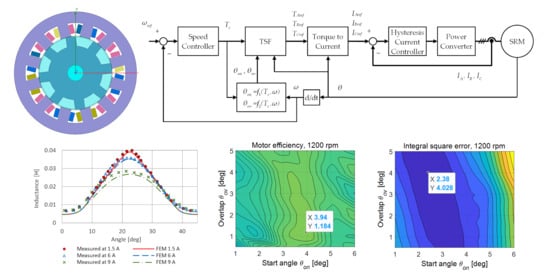
2. Modeling and Control of SRM
2.1. Switched Reluctance Motor and Power Converter
Control methods are tailored and optimized for the SRM that is commercially available on the market. It is a small 200 W three-phase 12/8 pole switched reluctance motor. Rated voltage is 120 V, and the maximum phase current is 6 A. The geometry of the motor is shown in Figure 1a. Each stator phase winding consists of four coils connected in a series-parallel manner. The width of the stator and rotor pole is almost the same. Therefore, inductance profile has a sharp peak in an aligned position, and transition from a motor to generator mode is fast.
The experimental setup uses a power converter that was built for measurement purposes. It has a standard asymmetric H-bridge topology to drive three phases of SRM (Figure 1b). A stabilized power supply supplies a DC-link of the power converter. The voltage can vary from 30 V to 120 V.
2.2. FEM Model
The FEM model of SRM was built in ANSYS Maxwell according to the dimensions of the motor and electrical measurement. When creating the model, a compromise solution was chosen between the mesh size and the computational time. The total number of elements is 11,110 in the 2D model. The mesh is denser in the air gap. The additional leakage inductance models the effect of the end winding leakage flux. The magnetic vector potential is zero on the outer circumference of the yoke. The comparison of the simulation results with the electrical measurement led to the selection of the B-H characteristic corresponding to the electrical steel M400.
The SRM model is driven by three-phase asymmetric H-bridge created in ANSYS Simplorer. The control algorithms are also programmed in ANSYS Simplorer. Figure 2 shows magnetic field distribution in the FEM model of the studied motor for aligned rotor position 22.5° (a) and for 7.2° (b). Figure 2c shows simulated motor characteristics for a maximum phase current of 6 A and 120 V DC-link voltage. The FEM model verification is described in Section 3.2.
2.3. SRM Control Methods
The switched reluctance motor is controlled by two methods. The first method is a Firing Angle Modulation, and the second one is a control method with Torque Sharing Functions.
2.3.1. Firing Angle Modulation
The firing angle modulation method is quite straightforward and can be easily implemented. The asymmetric H-bridge converter allows controlling the electric current in each stator phase winding independently by using a simple hysteresis controller. Each motor phase creates torque only in a limited angle interval, and the phases alternate one after the other. Therefore, the current is switched on at the angle θon and switched off at the angle θoff. The hysteresis current controller controls the current level inside the angle interval θon and θoff. Figure 3a shows simulated current waveforms of one phase as a function of a rotor angle for different speeds. The shape of the phase current cannot be fully controlled at an available DC-link voltage as it depends on the inductance profile and sampling frequency of the hysteresis controller. The current rising is fast because the phase inductance is low. At the end of the current impulse, the inductance is highest as the stator and rotor poles are aligned. Therefore, the electric current decay is slow, and it can create negative torque, especially at high speeds. Average motor torque corresponds to the current reference Iref and, of course, to the θon and θoff values. The value of Iref is an output of the speed controller. Figure 3b shows the block diagram of the firing angle modulation method. The procedure to calculate firing angles θon and θoff is described in Section 2.3.2.
2.3.2. Firing Angles Calculation
The phase current generates torque in a rotor angle region, where the phase inductance is changing due to a rotor position change. The electric current rise time is defined by the inductance and the applied voltage. Therefore, the turn-on angle θon shall precede the increase in inductance to start to generate the desired torque from the very beginning. If the current reaches the specified level too early, it creates a copper loss only. If the current does not reach the specified level at a defined angle, the torque is less than it could be. An early turn-off angle θoff causes torque to drop. However, a late turn-off of the current causes a negative torque to be generated.
A calculation of the turn-on angle θon is given in [16,17] based on the assumption, that the inductance profile has constant minimum inductance, then the inductance starts to rise at angle θm. The value of the current should reach the reference value at this point, and θon can be calculated as follows:
where θon is turn-on angle (degrees), θm is rotor angle (degrees) where the inductance begins to rise, Lu is the inductance in unaligned position, Iref is a reference current from speed controller, n is rotor speed (rpm), and VDC is the supply voltage. This equation neglects the actual shape of the inductance profile. Therefore, a set of simulation experiments was planned and performed to obtain a more precise formula for turn-on angle calculation. An extrapolation of collected data leads to the formula:
where Iref0 is a reference current from speed controller at angle 0°, and Imax is a maximum reference current.
The formula for calculation of turn-off angle is:
where I15 is a phase winding current at angle 15°, and VDC is a voltage applied on winding inductance at turn-off time. This formula was derived from the linear approximation of the current fall time. Equations (2) and (3) give angle values for first phase A. Angle values for phases B and C are shifted by 15° and 30°, respectively. Formulas (2) and (3) are valid only for the given SRM and used power converter with a DC-link voltage of 120 V.
2.3.3. Torque Sharing Functions
The motor torque created by consecutive phases is overlapping. Torque sharing function defines a required torque profile for each energized phase that the total motor torque has a small ripple. The shape of TSF can be chosen arbitrarily or is calculated according to selected criteria. Figure 4 shows sinusoidal TSF defined on the interval (0, θp) as follows [10]:
where θ is the rotor angle, θp = 2π/8 is the rotor pole pitch, θon is the turn-on angle, θov is the overlap angle, θoff = θon + 2π/24 is the turn-on angle of the next phase, Tc is the torque command, fup(θ) is the rising, and fdn(θ) the declining part of the TSF shape.
The block diagram of used TSF-based control is shown in Figure 5. The torque command Tc from the Speed Controller is translated into three torque profiles TAref, TBref, and TCref for each motor phase in the TSF block using Equations (4)–(6). The Torque to Current block translates the torque profile to current reference utilizing a look-up table obtained from the FEM model. A Hysteresis Current Controller is used to control phase currents. Optimal TSF parameters θon and θov are calculated by functions f1(Tc,ω) and f2(Tc,ω) from torque command Tc and actual rotor speed ω. The next section explains how to construct functions f1 and f2.
2.3.4. Optimization of TSF
The objective function needs to be defined to formulate an optimization problem. Three criteria are selected in this research to find optimal values of parameters θon and θov:
- Efficiency η
- Relative torque ripple Tripwhere Tmax, Tmin, and Tavg are the maximum torque, the minimum torque, and average torque, respectively.
- Integral square error criterion ISEwhere T, and Tavg are the instantaneous torque and average torque, respectively, measured in a time-interval (t1, t2). This objective function is a measure of overall torque oscillation.
Simulation experiments calculate the numerical value of an objective function. One simulation run is needed for each individual combination of parameters θon and θov. Calculations for all combinations in all operating points are time-consuming. Therefore, a workaround is used: the shape of the objective function is replaced by the interpolation function calculated from a limited set of combinations of θon and θov values. Then, the extreme of the interpolated function determines the optimal parameters for one operating point defined by torque and speed. The procedure described above is repeated to obtain a sufficient number of function points of f1(Tc,ω) and f2(Tc,ω). Functions obtained in this way are approximations of the optimal solution. Results from optimization are presented in Section 3.3.1.
The described off-line optimization procedure is an alternative to other optimization methods, such as the genetic algorithm. Its advantage is that, unlike genetic algorithms, it does not need new FEM computation when the objective function changes. Instead, the new values of the objective functions are calculated from the interpolated functions for which the computation time is significantly shorter. Once the interpolated functions have been enumerated, no further FEM computation is needed to apply different types of multi-objective optimization.
It must be said that the ability of the current controller to follow the reference current derived from the TSF is limited, especially at high speed. Therefore, the phase torque may not track the TSF. However, described off-line optimization involves the influence of the current controller to the actual phase torque. There is a possibility to reduce the torque ripple further using a more advanced current controller. Authors in [17] propose a predictive pulse width modulation (PWM) current control method that serves this purpose and a modified proportional–derivative (PD) controller that lowers the transient response overshoot is described in [25].
3. Results
3.1. Experimental Setup
The experimental setup consists of 200 W three-phase 12/8 pole switched reluctance motor connected to an induction machine that serves as load. Torque sensor KISTLER 4520A20 with CoMo torque evaluation instrument 4700BP0UA was used to measure the torque, speed, and mechanical power on the shaft. Infratek 106A Power Analyzer measured input power. STM32F303RET6 microcontroller, with the control loop cycle time 50 µs, controlled the asymmetric H-bridge power converter.
3.2. FEM Model Verification
The FEM model of SRM was verified by comparing measured and calculated motor characteristics. Figure 6a shows measured and calculated inductance profiles for currents 1.5 A, 6 A, and 9 A [26]. The more significant deviation occurs at the current of 9 A, but this is not a problem as the operating currents are up to 6 A. Figure 6b shows measured and calculated torque profiles for phase currents 2 A, 4 A, and 6 A. Phase currents from the measurement and FEM model are shown in Figure 7a. The behavior of the FEM hysteresis current controller slightly differs from the real one because it depends on the controller sampling, hysteresis-band, and the current sensor response time. Figure 7b shows the measured and calculated efficiency of the drive. Mechanical and power converter losses are included. Despite the above differences, the authors believe that the match between model and measurement is sufficient to allow meaningful conclusions to be drawn from the simulation results.
3.3. Simulation Results
3.3.1. Calculation of Optimal TSF Parameters
Results of preliminary simulation experiments were used to determine the range and number of values for speed, torque, θon, and θov parameters. Then, simulation runs for each parameter combination were calculated, and the values of selected objective functions were recorded. The Matlab piece-wise interpolating polynomials function uses recorded values to calculate interpolation function for each objective. The filled contour graph in Figure 8 visualizes the motor efficiency, relative torque ripple, and integral square error criterion for two operational points: torque 1 Nm, speed 600 rpm (Figure 8a), and 1200 rpm (Figure 8b). The data tips show values of θon and θov parameters for the specified operating point that are optimal according to the corresponding objective function. Figure 9 shows optimal values of θon and θov as a function of speed separately in two graphs for speeds 300, 600, 900, and 1200 rpm. Simulated motor torque for TSF-based control with optimal parameter settings according to three objective functions is shown in Figure 10a for speed 600 rpm, and in Figure 10b for speed 1200 rpm.
3.3.2. Comparison of FAM and TSF-based control
The comparison of the firing angle modulation method and TSF-based control method according to maximal efficiency, minimal relative torque ripple, and minimum integral square error criteria is presented in Figure 11. Each graph shows the value of the corresponding objective function for four cases. The first three cases are TSF motor control methods optimized according to the defined objective functions. The fourth case is the FAM method, where θon and θoff are calculated according to Equations (2) and (3), respectively.
Figure 11a shows that the control with TSF optimized for efficiency has the highest efficiency value, but the differences between the other control methods are small, and the efficiency of the FAM is only 1.7% lower (Figure 11a). As shown in Figure 11b, the control with TSF optimized for relative torque ripple, and TSF optimized for integral square error has a small value of relative torque ripple, unlike the FAM and TSF, optimized for efficiency, that has a large value of relative torque ripple. Similar results are displayed in Figure 11c for the integral square error criterion.
Inconsistency in the calculated data appeared in Figure 11c. The value of integral square error criterion (ISE) should be the smallest one for TSF optimized for ISE. However, TSF optimized for relative torque ripple has the lowest value of ISE for 300 and 900 rpm. This unexpected finding shows that the accuracy of a numerical solution is limited.
4. Discussion and Conclusions
This paper presents tailoring and a comparison of two methods to control a commercially available small switched reluctance motor, whose construction is not optimized for the minimization of torque ripple. Furthermore, a new approach to off-line evaluation of objective functions for motor control optimization that reduce computational time is presented.
The first control method is a firing angle modulation, which can be easily implemented on a low-cost microcontroller if the price of the drive is critical for a certain market segment. The second one is a control method with Torque Sharing Functions, which is more complex and uses torque-angle-current look-up tables calculated in advance by FEM.
Objective functions of the control methods optimization are maximal efficiency, minimal relative torque ripple, and minimum integral square error criterion.
The research shows that FAM has the same overall efficiency as TFS optimized for the torque ripple and TSF optimized for integral square error, but FAM has a high torque ripple. The results of simulation experiments show that the presented off-line optimization procedure can find optimal parameters matching the selected objective. However, it is not possible to achieve the lowest torque ripples and the highest efficiency at the same time. This is in line with the results of other authors [11,19,20,22]. Multi-objective optimization should be used to solve the problem. Herein, the results from the presented off-line optimization procedure can serve this purpose. Once the set of simulation runs is executed and the values of each objective function are calculated, another multi-objective optimization, e.g., Pareto-optimal approach, can be applied.
To conclude, the efficiency of FAM control is comparable with a more advanced TSF method, and it makes sense to use it in cost-effective drives where the high torque ripple does not affect the device, e.g., pumps and fans. More advanced SRM control must be used if low torque ripple is required. The presented off-line optimization procedure can be used for single or multi-objective optimization.
The main contribution of this paper is the quantitative comparison of two control methods for SRM that can help in decision making in the process of designing a commercial drive for existing off-the-shelf switched reluctance motors. The second contribution is the explanation of how to tailor and optimize the parameters of control methods using FEM. Presented off-line calculations with the objective function interpolation reduce the computational time. Once the objective functions have been enumerated, no further FEM computation is needed to apply different types of multi-objective optimization.
In future research, the attention will be given to on-line optimization where the objective function value is obtained from the direct measurement of efficiency, vibration, or acoustic noise.
Author Contributions
Conceptualization, P.B. and Ž.F.; methodology, P.B. and Ž.F.; software ANSYS Maxwell and Simplorer, Ž.F.; software Matlab, P.B.; validation, P.B. and Ž.F.; formal analysis, Ž.F.; investigation, P.B. and Ž.F.; writing P.B.; funding acquisition, Ž.F. All authors have read and agreed to the published version of the manuscript.
Funding
This work was supported by the Slovak Research and Development Agency under the contract No. APVV-16-0206 and APVV-15-0750.
Conflicts of Interest
The authors declare no conflict of interest.
Abbreviations and Symbols
| ATC | Average Torque Control |
| CPLD | Complex Programmable Logic Devices |
| DITC | Direct Instantaneous Torque Control |
| DSP | Digital Signal Processor |
| DTC | Direct Torque Control |
| ISE | Integral Square Error criterion |
| FAM | Firing Angle Modulation method |
| FBL | Feedback Linearization control |
| FEM | Finite Element Method |
| FPGA | Field-Programmable Gate Array |
| IC | Intelligent Control |
| ILC | Iterative Learning Control |
| MPU | Micro Processor Unit |
| rpm | revolution per minute [r/min] |
| SRM | Switched Reluctance Motor |
| TSF | Torque Sharing Function |
| f1(Tc,ω) | The function for optimal value of θon parameter of TSF |
| f2(Tc,ω) | The function for optimal value of θov parameter of TSF |
| fdn(θ) | The declining part of the TSF shape |
| fup(θ) | The rising part of the TSF shape |
| I15 | The phase current at angle 15° |
| IA, IB, IC | The instantaneous current in phase A, B, and C |
| IAref, IBref, ICref | The reference current for phase A, B, and C |
| Imax | The maximum current reference |
| Iref | The reference current |
| Iref0 | The reference current at angle 0° |
| Lu | The inductance in unaligned position |
| n | The rotor speed in [rpm] |
| TAref, TBref, TCref | The torque profile for motor phase A, B, and C |
| Tavg | The average torque |
| Tc | The torque command |
| Tmax | The maximum torque on the interval |
| Tmin | The minimum torque on the interval |
| Trip | The relative torque ripple |
| VDC | The supply voltage |
| η | The efficiency |
| θ | The rotor angle |
| θm | The rotor angle where the inductance begins to rise |
| θoff | The turn-off angle |
| θon | The turn-on angle |
| θov | The overlap angle |
| θp | The rotor pole pitch |
| ω | The rotor angular speed |
| ωref | The rotor angular speed reference |
References
- Santo, A.E.; Calado, M.R.; Cabrita, C.M. Sliding Mode Position Controller for a Linear Switched Reluctance Actuator. In Sliding Mode Control; IntechOpen: London, UK, 2011; pp. 181–202. [Google Scholar] [CrossRef] [Green Version]
- Ahn, J.-W.; Lukman, G.F.L. Switched Reluctance Motor: Research Trends and Overview. China Electrotech. Soc. Trans. Electr. Mach. Syst. 2019, 2, 339–347. [Google Scholar] [CrossRef]
- Jarvis, R. Davidson’s locomotive: How did he do it? Eng. Sci. Educ. J. 1996, 5, 281–288. [Google Scholar] [CrossRef]
- Lawrenson, P.; Stephenson, J.; Blenkinsop, P.; Corda, J.; Fulton, N. Variable-speed switched reluctance motors. IEE Proc. B Electr. Power Appl. 1980, 127, 253. [Google Scholar] [CrossRef]
- More, A. Switched Reluctance Motors Market 2019 Industry Size by Global Major Companies Profile, Competitive Landscape and Key Regions 2025. 2019. Available online: https://www.theexpresswire.com/pressrelease/Switched-Reluctance-Motors-Market-2019-Industry-Size-by-Global-Major-Companies-Profile-Competitive-Landscape-and-Key-Regions-2025-360-Research-Report_10273615 (accessed on 21 March 2020).
- Kozuka, S.; Tanabe, N.; Asama, J.; Chiba, A. Basic characteristics of 150,000r/min switched reluctance motor drive. In Proceedings of the IEEE PES General Meeting, Pittsburgh, PA, USA, 20–24 July 2008; pp. 1–4. [Google Scholar] [CrossRef]
- Miller, T. Optimal design of switched reluctance motors. IEEE Trans. Ind. Electron. 2002, 49, 15–27. [Google Scholar] [CrossRef] [Green Version]
- Belhadi, M.; Krebs, G.; Marchand, C.; Hannoun, H.; Mininger, X. Geometrical optimization of SRM on operating mode for automotive application. Electr. Eng. 2017, 100, 303–310. [Google Scholar] [CrossRef] [Green Version]
- Gan, C.; Wu, J.; Sun, Q.; Kong, W.; Li, H.; Hu, Y. A Review on Machine Topologies and Control Techniques for Low-Noise Switched Reluctance Motors in Electric Vehicle Applications. IEEE Access 2018, 6, 31430–31443. [Google Scholar] [CrossRef]
- Lin, C.-H.; Hwang, C.-C. High Performances Design of a Six-Phase Synchronous Reluctance Motor Using Multi-Objective Optimization with Altered Bee Colony Optimization and Taguchi Method. Energies 2018, 11, 2716. [Google Scholar] [CrossRef] [Green Version]
- Xue, X.; Cheng, K.-W.E.; Ho, S.L. Optimization and Evaluation of Torque-Sharing Functions for Torque Ripple Minimization in Switched Reluctance Motor Drives. IEEE Trans. Power Electron. 2009, 24, 2076–2090. [Google Scholar] [CrossRef]
- Evangeline, J.S.; Kumar, S.S.; Jayakumar, J. Torque modeling of Switched Reluctance Motor using LSSVM-DE. Neurocomputing 2016, 211, 117–128. [Google Scholar] [CrossRef]
- Ye, W.; Ma, Q.; Zhang, P. Improvement of the Torque-Speed Performance and Drive Efficiency in an SRM Using an Optimal Torque Sharing Function. Appl. Sci. 2018, 8, 720. [Google Scholar] [CrossRef] [Green Version]
- Zhang, M.; Bahri, I.; Mininger, X.; Vlad, C.; Xie, H.; Berthelot, E. A New Control Method for Vibration and Noise Suppression in Switched Reluctance Machines. Energies 2019, 12, 1554. [Google Scholar] [CrossRef] [Green Version]
- Cheng, H.; Chen, H.; Yang, Z. Average torque control of switched reluctance machine drives for electric vehicles. IET Electr. Power Appl. 2015, 9, 459–468. [Google Scholar] [CrossRef]
- Fuengwarodsakul, N.H.; Menne, M.; Inderka, R.; De Doncker, R. High-Dynamic Four-Quadrant Switched Reluctance Drive Based on DITC. IEEE Trans. Ind. Appl. 2005, 41, 1232–1242. [Google Scholar] [CrossRef]
- Cai, H.; Wang, H.; Li, M.; Shen, S.; Feng, Y.; Zheng, J. Torque Ripple Reduction for Switched Reluctance Motor with Optimized PWM Control Strategy. Energies 2018, 11, 3215. [Google Scholar] [CrossRef] [Green Version]
- Bose, B.K.; Miller, T.J.E.; Szczesny, P.M.; Bicknell, W.H. Microcomputer Control of Switched Reluctance Motor. IEEE Trans. Ind. Appl. 1986, 22, 708–715. [Google Scholar] [CrossRef]
- Hamouda, M.; Szamel, L. Reduced Torque Ripple based on a Simplified Structure Average Torque Control of Switched Reluctance Motor for Electric Vehicles; Institute of Electrical and Electronics Engineers (IEEE): Piscataway, NJ, USA, 2018. [Google Scholar]
- Xue, X.D.; Cheng, K.W.E.; Cheung, N.C. Evaluation of torque sharing functions for torque ripple minimization of switched reluctance motor drives in electric vehicles. In Proceedings of the 2008 Australasian Universities Power Engineering Conference, Sydney, NSW, Australia, 14–17 December 2008; pp. 1–6. [Google Scholar]
- Ye, J.; Bilgin, B.; Emadi, A. An Extended-Speed Low-Ripple Torque Control of Switched Reluctance Motor Drives. IEEE Trans. Power Electron. 2014, 30, 1457–1470. [Google Scholar] [CrossRef]
- Li, H.; Bilgin, B.; Emadi, A. An Improved Torque Sharing Function for Torque Ripple Reduction in Switched Reluctance Machines. IEEE Trans. Power Electron. 2018, 34, 1635–1644. [Google Scholar] [CrossRef]
- Ro, H.-S.; Lee, K.-G.; Lee, J.-S.; Jeong, H.-G.; Lee, K.-B. Torque Ripple Minimization Scheme Using Torque Sharing Function Based Fuzzy Logic Control for a Switched Reluctance Motor. J. Electr. Eng. Technol. 2015, 10, 118–127. [Google Scholar] [CrossRef] [Green Version]
- Panek, D.; Orosz, T.; Karban, P. Artap: Robust Design Optimization Framework for Engineering Applications. In Proceedings of the 2019 Third International Conference on Intelligent Computing in Data Sciences (ICDS), Marrakech, Morocco, 28–30 October 2019; pp. 1–6. [Google Scholar]
- Sovicka, P.; Rafajdus, P.; Vavrus, V. Switched reluctance motor drive with low-speed performance improvement. Electr. Eng. 2019, 102, 27–41. [Google Scholar] [CrossRef]
- Ferkova, Z.; Suchy, L.; Cernohorsky, J. Measurement of switched reluctance motor parameters. In Proceedings of the 2017 19th International Conference on Electrical Drives and Power Electronics (EDPE), Dubrovnik, Croatia, 4–6 October 2017; pp. 287–290. [Google Scholar] [CrossRef]
Figure 1.
(a) Geometry of the switched reluctance motor; (b) standard asymmetric H-bridge converter topology.
Figure 1.
(a) Geometry of the switched reluctance motor; (b) standard asymmetric H-bridge converter topology.

Figure 2.
Magnetic field distribution in the finite element method (FEM) model, phase current 6 A: (a) aligned position, rotor angle 22.5 degrees; (b) rotor angle 7.2 degrees; (c) Power–Speed and Torque–Speed characteristics.
Figure 2.
Magnetic field distribution in the finite element method (FEM) model, phase current 6 A: (a) aligned position, rotor angle 22.5 degrees; (b) rotor angle 7.2 degrees; (c) Power–Speed and Torque–Speed characteristics.

Figure 3.
(a) Current waveform at speed 300, 600, and 900 rpm, 120 V; (b) block diagram of the firing angle modulation method.
Figure 3.
(a) Current waveform at speed 300, 600, and 900 rpm, 120 V; (b) block diagram of the firing angle modulation method.

Figure 4.
Sinusoidal torque sharing function.

Figure 5.
Block diagram of the switched reluctance motor (SRM) control using torque sharing function (TSF) with optimized parameters θon and θov.
Figure 5.
Block diagram of the switched reluctance motor (SRM) control using torque sharing function (TSF) with optimized parameters θon and θov.

Figure 6.
(a) Comparison of measured and calculated inductance profiles; (b) measured and calculated torque profile.
Figure 6.
(a) Comparison of measured and calculated inductance profiles; (b) measured and calculated torque profile.

Figure 7.
(a) Comparison of measured and calculated phase current, θon = 0°, θoff = 19.25°, speed is 1200 rpm, DC-link voltage is 100 V, load torque is 1 Nm; (b) measured and calculated motor efficiency for constant angles θon = 0°, θoff = 17.6°, mechanical and power converter losses are included.
Figure 7.
(a) Comparison of measured and calculated phase current, θon = 0°, θoff = 19.25°, speed is 1200 rpm, DC-link voltage is 100 V, load torque is 1 Nm; (b) measured and calculated motor efficiency for constant angles θon = 0°, θoff = 17.6°, mechanical and power converter losses are included.

Figure 8.
Values of the objective functions at load torque 1 Nm: (a) speed 600 rpm; (b) speed 1200 rpm.
Figure 8.
Values of the objective functions at load torque 1 Nm: (a) speed 600 rpm; (b) speed 1200 rpm.

Figure 9.
Optimal parameter values at load torque 1 Nm: (a) start angle θon; (b) overlap θov.

Figure 10.
Simulated motor torque for optimal parameter values at load torque 1 Nm: (a) speed 600 rpm; (b) speed 1200 rpm.
Figure 10.
Simulated motor torque for optimal parameter values at load torque 1 Nm: (a) speed 600 rpm; (b) speed 1200 rpm.

Figure 11.
Comparison of the firing angle modulation (FAM) method and TSF at load torque 1 Nm: (a) efficiency; (b) relative torque ripple; (c) integral square error.
Figure 11.
Comparison of the firing angle modulation (FAM) method and TSF at load torque 1 Nm: (a) efficiency; (b) relative torque ripple; (c) integral square error.

© 2020 by the authors. Licensee MDPI, Basel, Switzerland. This article is an open access article distributed under the terms and conditions of the Creative Commons Attribution (CC BY) license (http://creativecommons.org/licenses/by/4.0/).
Share and Cite
MDPI and ACS Style
Bober, P.; Ferková, Ž. Comparison of an Off-Line Optimized Firing Angle Modulation and Torque Sharing Functions for Switched Reluctance Motor Control. Energies 2020, 13, 2435. https://doi.org/10.3390/en13102435
AMA Style
Bober P, Ferková Ž. Comparison of an Off-Line Optimized Firing Angle Modulation and Torque Sharing Functions for Switched Reluctance Motor Control. Energies. 2020; 13(10):2435. https://doi.org/10.3390/en13102435
Chicago/Turabian StyleBober, Peter, and Želmíra Ferková. 2020. "Comparison of an Off-Line Optimized Firing Angle Modulation and Torque Sharing Functions for Switched Reluctance Motor Control" Energies 13, no. 10: 2435. https://doi.org/10.3390/en13102435
Note that from the first issue of 2016, this journal uses article numbers instead of page numbers. See further details here.