Review of Heat Recovery Technologies for Building Applications


Department of Architecture and Built Environment, Faculty of Engineering, The University of Nottingham, University Park, Nottingham NG7 2RD, UK
*
Author to whom correspondence should be addressed.
Energies 2019, 12(7), 1285; https://doi.org/10.3390/en12071285
Submission received: 27 January 2019
/
Revised: 20 March 2019
/
Accepted: 23 March 2019
/
Published: 3 April 2019
(This article belongs to the Special Issue Sustainable Energy Technologies for Eco Cities and Environment—Papers from the 17th International Conference on Sustainable Energy Technologies (SET2018))
Abstract
:In recent years, interest in heat recovery systems for building applications has resurged due to concerns about the energy crisis and global climate changes. This review presents current developments in four kinds of heat recovery systems for residential building applications. A extensive investigation into the heat recovery integrated in energy-saving systems of residential buildings is also covered, including passive systems for building components, mechanical/natural ventilation systems, dehumidification systems, and the thermoelectric module (TE) system. Based on this review, key issues have been identified as follows: (1) The combination of heat recovery and energy-efficient systems could be considered as a promising approach to reduce greenhouse gas emissions and make residential buildings meet high performance and comfort requirements. However, real-life evaluation of these systems with economic analysis is insufficient; (2) When heat recovery is applied to mechanical ventilation systems, issues such as pressure leakages and air shortcuts should be addressed; (3) The heat pipe heat recovery system enjoys more potential in being combined with other sustainable technologies such as thermoelectric modules and solar energy systems due to its advantages, which include handy manufacturing and convenient maintenance, a lack of cross contamination, and greater thermal conductance.
1. Introduction
Rapid growth in world energy use has caused concerns about supply difficulties, energy depletion, and serious environmental impacts. For instance, climate change and ozone layer depletion have been key issues with which people have had to deal [1]. According to the reviewed literature, building energy consumption, including its operation and maintenance, currently accounts for 40% of the total global energy demand [2,3]. Moreover, heating, ventilation, and air conditioning systems (HVACs) consume 40–60% of a building’s energy consumption, with the precise value varying by climate [1]. Meanwhile, this energy consumption causes a large amount of greenhouse gas emissions, such as the emission of carbon dioxide (CO2). It is predicted that continued increases in carbon dioxide emissions will lead to major climate change [4]. Therefore, governments are making efforts to develop energy-saving and eco-friendly building technologies [5].
A great many energy-saving processes and techniques have been proposed for residential building applications, including recovering the waste energy of buildings, which is also referred to as a heat recovery system. In the context of the global energy crisis, on the one hand, the improvement of indoor air quality is required. On the other hand, there is an urgent need to promote energy-saving emission reductions in the field of HVAC. The application of air-to-air heat recovery would solve the contradiction between abundant fresh air supply and the reduction of energy consumption. According to Cuce et al., heat recovery systems are regarded as a greatly promising technology because of their ability to provide significant energy savings for residential buildings [6].
The purpose of this review is partly to summarize the current development of heat recovery systems for residential building applications, including their normal types, characteristics, and technical energy-saving possibilities, and partly to discuss the application of heat recovery in energy-efficient systems of buildings, including heat recovery combined with passive systems, mechanical ventilation systems, dehumidification systems, and thermoelectric module (TE) systems of buildings. Finally, a summary and outlook of these systems will be presented.
2. The Definition of Heat Recovery Systems
Heat recovery is often referred to as a device operating between two air sources at different temperatures which transfers energy from one side to the other. In other words, it is based on preheating the incoming air to the interior through recycled waste heat. In general, heat recovery systems could be classified into sensible heat recovery and enthalpy heat recovery. Because of its ability to recover both the sensible heat and the latent heat, enthalpy heat exchangers have a better sustainability effect because of the large proportion of the wet load in the ventilation system and the requirements of the indoor air humidity for modern buildings.
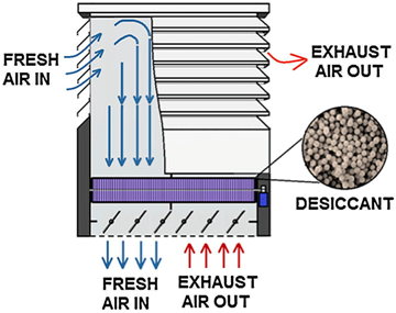
A representative heat exchanger system in residential buildings is usually composed of a heat exchanger core, a fresh air inlet and separate contaminated air exhaust outlet, and a fan, as shown in Figure 1 [7]. At present, heat recovery systems can recover about 60–95% of waste energy, which is very promising [6]. This review focuses on four categories of heat recovery for sustainable residential building systems, including rotary wheel, fixed-plate, heat pipe, and run-around systems, which will be discussed in later sections.
3. Types of Heat Recovery Systems for Residential Building Applications
According to the classification of different constructions, heat recovery systems can be divided into four types: rotary wheel, fixed-plate, heat pipe, and run-around.
3.1. Rotary Wheel
The rotary wheel heat recovery system is a motor-driven rotating porous wheel. When heat and moisture exchange happen, the two streams alternately pass through the wheel, as shown in Figure 2. The speed of rotors is usually low, ranging from 3 rpm to 15 rpm [7].
The overall efficiency of rotary wheel heat recovery is generally much higher than that of any other air-side heat recovery system due to the nature of the heat wheels, which allow heat to transfer from the exhaust stream to the supply stream without having to pass directly through the exchange medium. Normally, rotary wheel heat recovery is able to obtain a heat exchange efficiency of above 80% [7]. It is stated in [8] that the rotary wheel system has been proven to be one of the most efficient solutions for handling the moisture carried by the ventilation air. However, the rotary wheel heat recovery barely recovers 40% of the available enthalpy. Atmospheric conditions [9], the air mixing rate [10], rotation speed [11], and wheel materials [12] could be the major contributing factors in terms of the performance of rotary wheel heat recovery have a significant influence.
Many researchers have been working on achieving high performance of rotary wheel heat recovery. The optimal values of length and porosity can be obtained through the numerical model from Dallaire et al. [13]. The schematic representation of the optimal rotary wheel is shown in Figure 3 [13].
Besides their high heat transfer efficiency, rotary wheels can also recover both sensible and latent heat, which makes them able to be desiccant wheels for dehumidification and enthalpy recovery [14,15].
With regard to economic factors, a recent study in Chicago showed that the application of a rotary wheel heat exchanger enjoys a much shorter payback period in new buildings (less than one year) than in retrofitted existing building (two to four years) [16]. Another work from Chicago found that normally, total life cycle costs are 25–50% lower with the application of a rotary wheel than without it [17].
All the aforementioned studies show the advantages of the rotary wheel heat exchanger, these advantages being its rather high heat exchanger effectiveness and relatively short payback period [16]. However, the development of rotary wheel heat recovery is limited by the problems of air short circuiting and cross contamination [18]. Air short circuits can circulate air in unintended directions, greatly reducing the efficiency of the system.
3.2. Fixed-Plate
Fixed-plate heat exchangers use thin plates stacked together to create flow channels, which are illustrated below in Figure 4 [7]. The first plate type heat exchanger was invented by Dr Richard Seligman in 1923 and was used for indirect heating/cooling fluid [19]. There are three types of airflow arrangement, including counter flow, cross flow, and parallel flow. When the plates are made of a material with thermal conductivity and moisture permeability, they constitute an enthalpy heat exchanger. Mardiana-Idayu et al. introduced an experiment to investigate a novel enthalpy recovery system with a micro heat and mass cell cycle core, as shown as Figure 5. The results showed that the sensible energy efficiency was close to 66%, whereas for latent energy it was 59% [20]. Similarly, Nasif et al. conducted a fixed-plate heat recovery system by using a porous membrane material, shown as Figure 6. The thermal effectiveness of the new system was found to be about 75% of the sensible energy efficiency and 65% for the latent equivalent [21].
When plates (including metal plates and plastic plates, etc.) cannot absorb moisture, the material thermal conductivity and geometry is paramount for recovery of sensible heat. Normally, sensible heat recovery can achieve a heat exchange rate between 50% and 80% [22]. The factors that could affect the heat transfer efficiency of fixed-plate type heat recovery include:
- Flow pattern [26].
Recently, some commercial products have achieved a better heat exchanger rate. One improved fixed-plate heat recovery system produced by a Danish company can achieve a heat recovery rate of 93%, as certificated by Passive House Institute, Darmstadt [27,28]. Therefore, fixed-plate type heat exchangers enjoy a promising future in higher thermal performance in residential building applications.
3.3. Heat Pipe
Heat recovery systems using heat pipes to transfer heat combine the principles of heat conduction and phase change to effectively transfer heat between two solid interfaces. The typical heat pipe consist of two closed tubes filled with working fluid [29]. The heat pipe transfers thermal energy from one side to the other side with a small temperature difference [30]. During operation, the condensed liquid travels to the evaporation section due to the wick structure exerting capillary action or the gravitational force [29].
Typical heat pipe exchangers can achieve thermal efficiency of around 50% [31]. Experiments from Shao et al. have proven that the efficiency of a heat pipe recovery system in a naturally ventilated house can achieve 50% with pressure loss less than 1 Pa [32]. The effectiveness will decrease with increasing air flow rate, and substandard thermal contact between plates and heat pipe occurs [33]. In terms of factors that could affect heat pipe effectiveness, there are some key points [34,35]: working fluid, the arrangement of the pipes, the air velocity and the inlet temperature of the evaporator part.
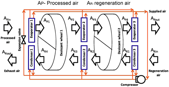
For the last decade, many researchers have focused on the application of heat pipe type recovery. El-Baky et al. have developed an experiment to test its thermal performance and to collect data for the effectiveness of heat pipe systems for heat recovery in air conditioning applications, shown as Figure 7. The results have shown that the heat transfer rate for both the evaporator and condenser sections has increased to around 48% [36].
From Yau et al. it can also be found that using heat pipe recovery systems can lead to significant energy savings in domestic appliances within tropical climates [37,38]. Recently, Diao et al. provided a new study involving a small flat heat pipe heat recovery device which applies a flat micro-heat pipe array with welded, serrated, and staggered fins on its surface, as shown in Figure 8. The results showed that the maximum heat exchange rate and coefficient of performance (COP) could be 78% and 91.9, respectively, under experimental conditions [39]. This study of a small flat heat pipe heat recovery system indicates the potential for improving the thermal performance of heat pipe heat recovery. However, further real-life evaluation is still needed.
In summary, heat pipe heat recovery enjoys the following advantages: handy manufacturing and convenient maintenance, a lack of cross contamination, and greater thermal conductance [40].
3.4. Run-Around
Run-around heat recovery systems consist of two individual heat exchangers and a coupling liquid, as shown in Figure 9. With the help of the pump, it allows liquid to transfer absorbed heat from one stream into the other side [7].
Run-around heat recovery can avoid cross contamination because of the separation of the two heat exchangers [41]. The heat exchange rate of run-around heat recovery ranges from 45% to 65% under normal conditions [7]. Using a run-around heat recovery system in a building can increase the ventilation airflow rate without increasing energy consumption [42]. As to the thermal performance of run-around heat recovery, Vali et al.’s experimental results showed that for a given total surface area of exchangers, the highest overall sensible effectiveness was achieved with exchangers which have a small exchanger aspect ratio [41].
In addition, the effectiveness of run-around heat recovery is significantly dependent on outdoor conditions. Run-around heat recovery systems are often positioned within the supply and exhaust air streams of industrial processes.
Table 1 compares the basic performance of different types of heat recovery systems.
By sorting through 100 research papers published in the last five years about the study of the application of heat recovery systems in residential buildings, such a summary could be given as follows. Figure 10 shows the distribution of the main studies according to the four heat recovery system types. Nearly one third of researchers were interested in heat pipe heat recovery (HPHR). Around 40% of these newly published articles were related to fixed-plate heat recovery (FPHR). About 21% of researchers focused on rotary wheel heat recovery. However, just 3% considered run-around heat recovery. Normally, run-around heat recovery systems are more popular in the industrial field and are not as common in domestic building applications. The following sections discussing fixed-plate, rotary wheel, and heat pipe heat recovery combined with energy-efficient systems for building applications.
4. Applications of Heat Recovery in Energy-Saving Systems of Residential Buildings
The combination of heat recovery and different energy-efficient systems could contribute to reducing heat loss, stabilizing heat flux, and improving the thermal performance of residential buildings. This section reviews the recent development in heat recovery combined with energy-efficient technologies of buildings over four subsections.
4.1. Heat-Recovery-Assisted Decentralized Ventilation System
Mechanical ventilation systems are applied for achieving the desired airflow and obtaining a comfortable interior environment. However, mechanical ventilation can consume much electrical energy, and, can at times increase household power consumption by up to 50% [43]. Tommerup et al. have reported that with heat recovery technology, up to 90% of ventilation heat loss (about 30–35 kWh/m2 per year) can be recovered depending on airtightness and the insulation of the building [2].
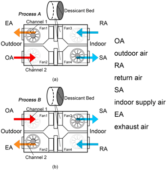
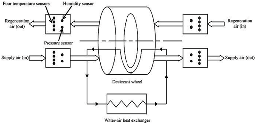
Compared with centralized ventilation, pressure loss can be minimized within decentralized ventilation, due to the shorter distance of the air routing [44]. Several researchers have tested the performance of heat recovery units with decentralized ventilation systems based on different outdoors conditions. Baldini et al. has conducted a decentralized cooling and dehumidification system, as shown in Figure 11. Multi-stage type heat recovery could help to reduce the temperature compared to a single heat exchanger. Experimental results showed that under an environment temperature of around 30 °C and a humidity ratio of 20 g/kg, the application of the multi-stage heat recovery could reach the preferred target, with the supply air at 14–15 °C and 8–9 g/kg. Additionally, because of the free reheating, the system is able to save about 4–5% of cooling energy demand [44].
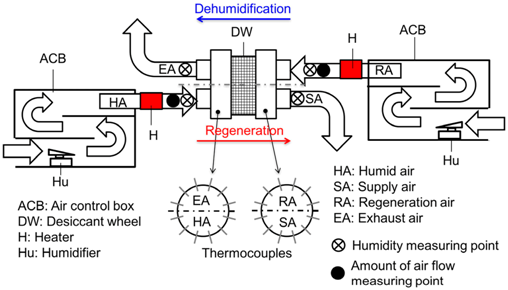
Another novel rotary wheel unit in Europe has been described by Smith et al. (shown in Figure 12), which uses plastic as the heat transfer material and was installed in the exterior wall of an individual room vent, requiring minimal space. Testing results indicated that this novel unit could recover about 84% of sensible heat with a ventilation rate of 7.8 L/s [45]. In addition, bypass leakage was observed during the experiment and the pressure drop reached around 18% [45]. High-pressure leakage could cause discomfort noise due to the higher fan speed required to achieve the desired vent rate. Therefore, proper sealing and slowing of the rotational speed to prevent frost accumulation should be ensured [45].
Plate type heat exchangers can also be integrated within ventilation systems. Coydon et al. have evaluated different facades combined with heat recovery ventilation units seasonally, as shown in Figure 13. The results showed that integration, including counter flow heat recovery, achieved recovery ranging from 64.6% to 70.0% of heat [46]. Another unit which adopted regenerative heat recovery could recover between 72.8% and 80.2% of heat [46].
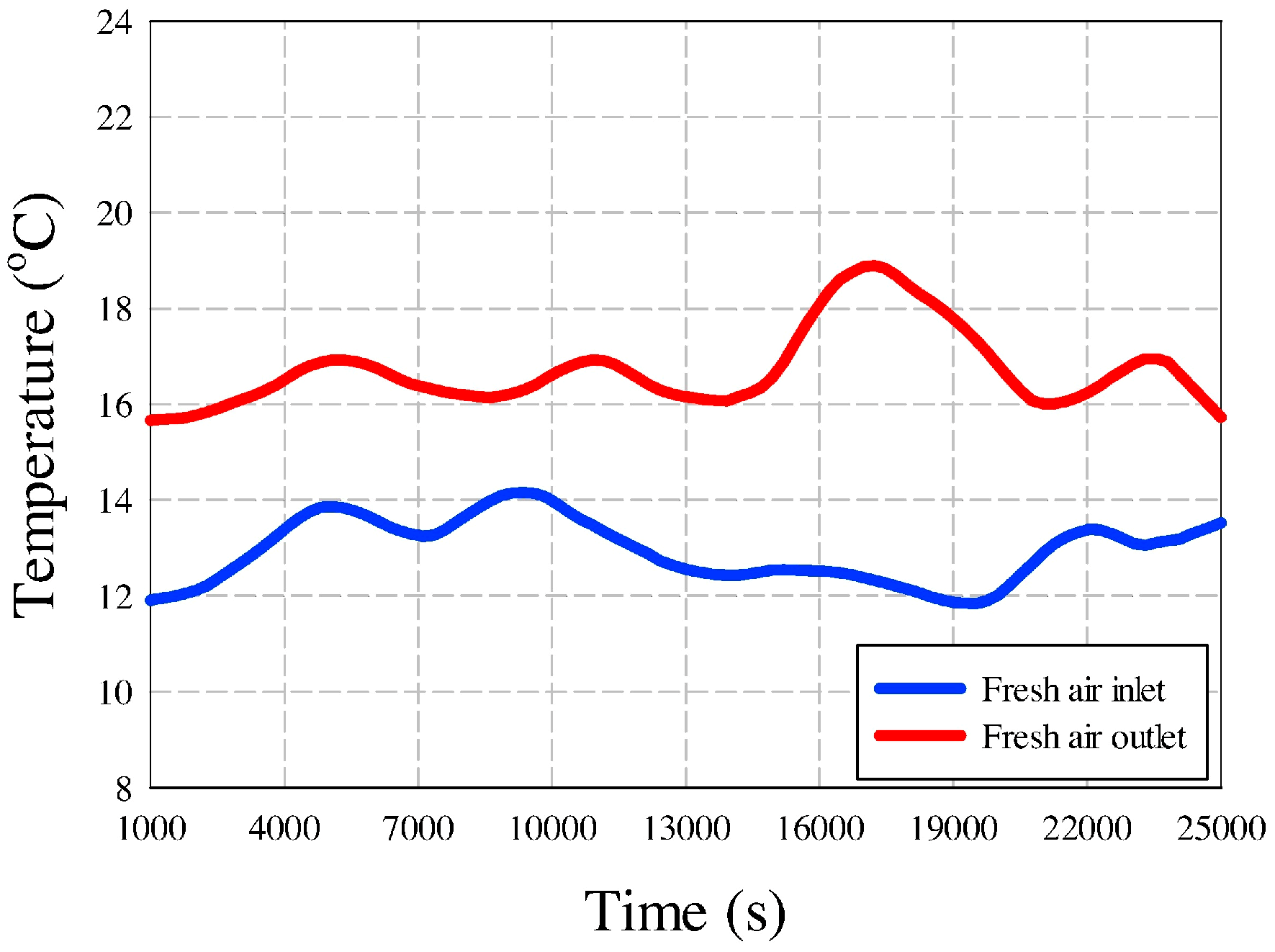
Recently, Cuce et al. proposed a novel polycarbonate heat recovery system. The experiment carried out measurements of temperature, relative humidity, and CO2 in a period of one week. The results indicated that through the application of the novel system within the testing house, a sensible increment, about 7 °C, was observed in the temperature of fresh air and a considerable decrease, about 4 °C, was achieved in the temperature of stale air [47]. They also showed that the average relative humidity in the testing room in the post-retrofit case was around 57%, which was within the desired range [47]. Figure 14 shows a temperature monitoring diagram during the testing period. The Cuce et al. experiments proved that by utilizing a combination of heat exchanger and ventilation, except for the mitigation of the heating or cooling load, the actual comfort conditions for indoor environments including CO2 concentrate and relative humidity reaching the desired range can also be achieved [47].
The following problems of integrated systems of heat recovery and decentralized ventilation can be found based on the aforementioned studies:
4.2. Heat Recovery Combined with Passive Systems for Building Components
Recently, heat recovery systems have been considered to be combined with building components such as building walls [48,49,50,51], roofs [52] and wind towers [53,54,55,56]. For example, it has been found that wind towers can provide significantly higher airflow rates than open windows with the same area [57]. However, application of wind towers is generally limited to tropical climates because seasonal temperatures in colder climates are too low to circulate directly into interior spaces. Wind towers are usually closed to avoid loss of heating energy in winter [55]. To address this limitation, combining heat recovery technology with wind towers could be a sensible solution. This kind of integration would be helpful for stabilizing the heat flux of buildings to reduce total energy consumption demands and enhance indoor thermal comfort.
Table 2 summarizes the studies of different building components integrated into heat recovery.
According to aforementioned studies, the superiority of the combination system can be described as follows:
- Can reach the desired airflow rate (8 L/s to 10 L/s per person) for wind tower combination system applications [54];
However, except for the potential of energy savings, the limitations of the systems may also be summarized:
4.3. Heat Recovery in Dehumidification Systems
Heat recovery is an important component of a dehumidification system [12]. Kabeel has stated that higher pressure drops and uneven humidity distribution are caused by using densely packed beds [58]. Many studies have been carried out to investigate the performance of dehumidification with heat recovery systems. Table 3 lists the development on common types of heat recovery, including rotary wheel exchangers, fixed-plate exchangers, and desiccant-coated heat exchangers, combined with dehumidification systems.
According to the aforementioned studies, the following summary could be given:
- Rotary desiccant wheels are always the better choice for adjusting the relative humidity of airflows [59]. These systems can achieve moisture removal rates of 1.7 g/kg~7 g/kg [60,61]. Rotary desiccant wheels find wide use in various climate conditions, mostly in humid and hot climates. However, more optimal models and verification are needed, including extensive cross-sectional area [62], airflow and rotation speed control [63], and lower pressure drop strategies [59];
- For fixed-plate heat exchangers, enthalpy heat recovery can improve frost resistance compared to fixed-plate sensible heat recovery, as well as better sensible and latent effectiveness and smaller space due to its more compact design compared to common cross-flow heat recovery system [64]. Fixed-plate enthalpy heat recovery enjoys a bright future in residential building applications as it helps to avoid cross contamination and to improve air quality with the dehumidification system. To achieve better thermal performance of enthalpy heat exchangers and more wide-ranging applications for different climate conditions, increasing transfer units or changing the properties of membrane materials chemically might be considered;
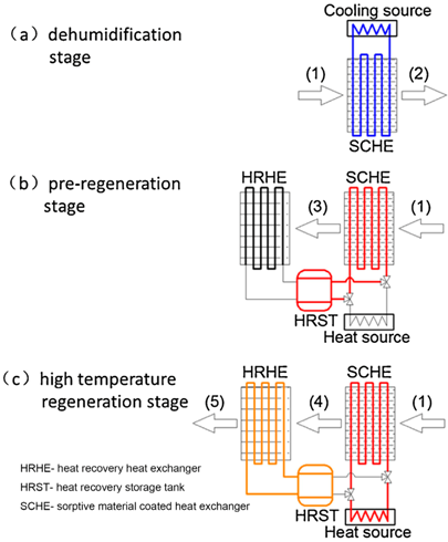
- Solid desiccant cooling technology is energy-saving and eco-friendly. Desiccant-coated heat recovery can transfer sensible and latent heat at the same time. It has been found that silica gel-coated heat recovery has better performance than polymer-coated heat recovery [65]. As the dehumidification and regeneration cycles greatly affect the dehumidification process, the best adjustable mode should be identified. However, it would be hard to repair or replace desiccant-coated heat recovery system, as this would bring about high costs to the system, making it unsuitable for small-scale residential building applications.
For all combination systems, strategies for controlling airflow and real-life investigation under different climate conditions are needed.
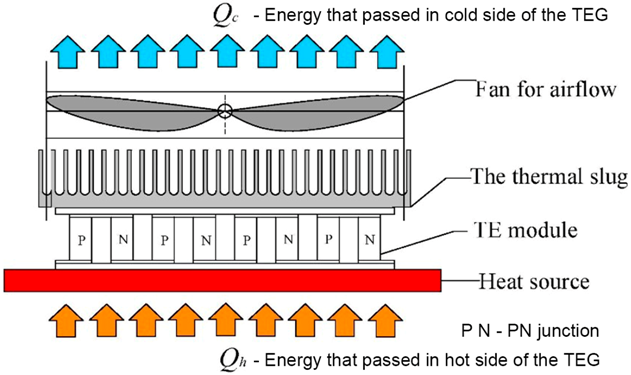
4.4. Heat Recovery with Thermoelectric Units
Since passive heat recovery systems take advantage of temperature differences between indoor and outdoor air streams, exhaust heat cannot be fully recovered. To tackle this disadvantage of conventional heat recovery, some researchers have proposed novel thermoelectric heat pump recovery systems [71,72,73,74]. Thermoelectric modules are solid state heat pumps that utilize the Peltier effect. During operation, DC current flows through the thermoelectric module, causing heat to be transferred from one side of the thermoelectric device to the other and creating a cold and hot side [75]. Temperature difference could be an approach to achieve heat recovery. Thermoelectric modules can also create electric energy when there is heat flux, which is called the thermoelectric generator (TEG) and works via the Seebeck effect [75]. Much focus has been placed on heat exchangers with thermoelectric generators for industrial and car waste heat recovery over decades, especially with the heat pipe type [76,77,78,79]. Currently, several studies about fixed-plate and heat pipe heat exchangers combined with thermoelectric modules for building ventilation application have appeared.
Table 4 lists current studies of heat recovery combined with thermoelectric units, including key features and economic evaluation.
From the current literature, some prospects and outlooks may be described:
- Heat exchangers combined with TE modules have more potential to achieve better thermal performance under optimal condition simulations [71]. However, further study is needed to investigate their long-term operation in domestic building applications;
- These novel systems benefit from their compact size, low electric energy consumption, environmental-friendly device structure, and rather low cost [71], which makes them a sensible choice with which to deal with heat loss during building ventilation;
- Since TE modules create redundant heat during their operation, the application of energy storage materials might be considered to balance out cooling and heating needs [72].
5. Summary
This review has presented a summary of heat recovery technologies for residential building applications, including the integration of heat recovery with some energy-saving systems. Some conclusions about and limitations of these current studies are the following:
- The combination of heat recovery with passive systems of building components can obviously reduce heat losses and inlet air flow rate. The combination of heat pipe and rotary wheel heat recovery with wind towers would be more compact than normal fixed-plate heat recovery [40]. However, unexpected noise from the DC motor for rotary wheel heat recovery could be an issue. Further real-scale testing is needed for complex building wall systems to improve their heat flux stability. In addition to wind towers and roofs, chimneys and transom could also be chosen to be combined with heat recovery technology.
- The effects of air pollution on decentralized ventilation with heat recovery systems lack further investigation. Future study is also needed to deal with bypass leakages during operation [44].
- Regarding heat recovery-assisted dehumidification systems, desiccant material should have low sensible heat effectiveness [63]. Meanwhile, for membrane heat recovery, increasing transfer units could be considered as a means to process better heat transfer.
- Heat recovery combined with TE modules should be developed due to its compact size, low electric energy consumption, environmental-friendly devices, and rather low cost. Further study is needed to investigate its long-term operation in domestic building applications.
- Heat pipe heat recovery systems enjoy more potential to be combined with other sustainable technologies such as thermoelectric modules and solar energy systems due to its advantages, including handy manufacturing and convenient maintenance, a lack of cross contamination, and greater thermal conductance [39,73].
Funding
This research was funded by Innovate UK (project code: 104019). And the APC was funded by WSSET (world society of sustainable energy technologies).
Conflicts of Interest
The authors declare no conflict of interest.
References
- Pérez-Lombard, L.; Ortiz, J.; Pout, C. A review on buildings energy consumption information. Energy Build. 2008, 40, 394–398. [Google Scholar] [CrossRef]
- Tommerup, H.; Svendsen, S. Energy savings in Danish residential building stock. Energy Build. 2006, 38, 618–626. [Google Scholar] [CrossRef]
- Omer, A.M. Energy, environment and sustainable development. Renew. Sustain. Energy Rev. 2008, 12, 2265–2300. [Google Scholar] [CrossRef]
- Cox, P.M.; Betts, R.a.; Jones, C.D.; Spall, S.A.; Totterdell, I.J. Acceleration of global warming due to carbon-cycle feedbacks in a coupled climate model. Nature 2000, 408, 184–187. [Google Scholar] [CrossRef]
- Zhao, D.X.; He, B.J.; Johnson, C.; Mou, B. Social problems of green buildings: From the humanistic needs to social acceptance. Renew. Sustain. Energy Rev. 2015, 51, 1594–1609. [Google Scholar] [CrossRef]
- Cuce, P.M.; Riffat, S. A comprehensive review of heat recovery systems for building applications. Renew. Sustain. Energy Rev. 2015, 47, 665–682. [Google Scholar] [CrossRef]
- Mardiana-Idayu, A.; Riffat, S.B. Review on heat recovery technologies for building applications. Renew. Sustain. Energy Rev. 2012, 16, 1241–1255. [Google Scholar] [CrossRef]
- Waugaman, D.G.; Kini, A.; Kettleborough, C.F. A review of desiccant cooling systems. J. Energy Resour. Technol. 1993, 115, 1–8. [Google Scholar] [CrossRef]
- Nóbrega, C.E.L.; Brum, N.C.L. Modeling and simulation of heat and enthalpy recovery wheels. Energy 2009, 34, 2063–2068. [Google Scholar] [CrossRef]
- Tu, R.; Liu, X.H.; Jiang, Y. Performance comparison between enthalpy recovery wheels and dehumidification wheels. Int. J. Refrig. 2013, 36, 2308–2322. [Google Scholar] [CrossRef]
- Ruivo, C.R.; Angrisani, G.; Minichiello, F. Influence of the rotation speed on the effectiveness parameters of a desiccant wheel: An assessment using experimental data and manufacturer software. Renew. Energy 2015, 76, 484–493. [Google Scholar] [CrossRef]
- Jani, D.B.; Mishra, M.; Sahoo, P.K. Solid desiccant air conditioning - A state of the art review. Renew. Sustain. Energy Rev. 2016, 60, 1451–1469. [Google Scholar] [CrossRef]
- Dallaire, J.; Gosselin, L.; da Silva, A.K. Conceptual optimization of a rotary heat exchanger with a porous core. Int. J. Therm. Sci. 2010, 49, 454–462. [Google Scholar] [CrossRef]
- Golubovic, M.N.; Hettiarachchi, H.D.M.; Worek, W.M. Evaluation of rotary dehumidifier performance with and without heated purge. Int. Commun. Heat Mass Transf. 2007, 34, 785–795. [Google Scholar] [CrossRef]
- Sauer, H.J.; Howell, R.H. Promise and potential of air-to-air energy recovery systems. Int. J. Refrig. 1981, 4, 182–194. [Google Scholar] [CrossRef]
- Simonson, C. Heat and Energy Wheels. In Encyclopedia of Energy Engineering and Technology; CRC Press: Boca Raton, FL, USA, 2007; Volume 2, pp. 794–800. [Google Scholar]
- Besant, R.W.; Simonson, C.J. Air-To-Air Energy Recovery. ASHRAE J. 2000, 42, 31–42. [Google Scholar]
- Roulet, C.A.; Heidt, F.D.; Foradini, F.; Pibiri, M.C. Real heat recovery with air handling units. Energy Build. 2001, 33, 495–502. [Google Scholar] [CrossRef]
- Richard, S.; Frederick, G.H. Plate-Type Heat Exchanger. U.S. Patent US2,193,405A, 12 March 1940. [Google Scholar]
- Mardiana-Idayu, A.; Riffat, S.B. An experimental study on the performance of enthalpy recovery system for building applications. Energy Build. 2011, 43, 2533–2538. [Google Scholar] [CrossRef]
- Nasif, M.; Al-Waked, R.; Morrison, G.; Behnia, M. Membrane heat exchanger in HVAC energy recovery systems, systems energy analysis. Energy Build. 2010, 42, 1833–1840. [Google Scholar] [CrossRef]
- Sammeta, H.; Ponnusamy, K.; Majid, M.A.; Dheenathayalan, K. Effectiveness charts for counter flow corrugated plate heat exchanger. Simul. Model. Pract. Theory 2011, 19, 777–784. [Google Scholar] [CrossRef]
- Abu-Khader, M.M. Plate heat exchangers: Recent advances. Renew. Sustain. Energy Rev. 2012, 16, 1883–1891. [Google Scholar] [CrossRef]
- Khan, T.S.; Khan, M.S.; Chyu, M.C.; Ayub, Z.H. Experimental investigation of single phase convective heat transfer coefficient in a corrugated plate heat exchanger for multiple plate configurations. Appl. Therm. Eng. 2010, 30, 1058–1065. [Google Scholar] [CrossRef]
- Lu, Y.; Wang, Y.; Zhu, L.; Wang, Q. Enhanced performance of heat recovery ventilator by airflow-induced film vibration (HRV performance enhanced by FIV). Int. J. Therm. Sci. 2010, 49, 2037–2041. [Google Scholar] [CrossRef]
- Gherasim, I.; Taws, M.; Galanis, N.; Nguyen, C.T. Heat transfer and fluid flow in a plate heat exchanger part I. Experimental investigation. Int. J. Therm. Sci. 2011, 50, 1492–1498. [Google Scholar] [CrossRef]
- Feist, W. Cool, Temperate Climate; Passive House Institute: Skive, Denmark, 2019. [Google Scholar]
- TECHNICAL INFORMATION HCC 2 Home Ventilation Unit for Suspended Ceiling. Available online: https://www.dantherm.com/media/2351812/home-ventilation-hcc2-datasheet.pdf (accessed on 6 March 2019).
- Yau, Y.H.; Ahmadzadehtalatapeh, M. A review on the application of horizontal heat pipe heat exchangers in air conditioning systems in the tropics. Appl. Therm. Eng. 2010, 30, 77–84. [Google Scholar] [CrossRef]
- Kreith, F.; Manglik, R.M.; Bohn, M.S. Principles of Heat Transfer; Cengage learning: Boston, MA, USA, 2012; ISBN 1133714854. [Google Scholar]
- Chaudhry, H.N.; Hughes, B.R.; Ghani, S.A. A review of heat pipe systems for heat recovery and renewable energy applications. Renew. Sustain. Energy Rev. 2012, 16, 2249–2259. [Google Scholar] [CrossRef]
- Shao, L.; Riffat, S. Flow loss caused by heat pipes in natural ventilation stacks. Appl. Therm. Eng. 1997, 17, 393–399. [Google Scholar] [CrossRef]
- Gan, G.; Riffat, S.B. Naturally ventilated buildings with heat recovery: CFD simulation of thermal environment. Build. Serv. Eng. Res. Technol. 1997, 18, 67–75. [Google Scholar] [CrossRef]
- Srimuang, W.; Amatachaya, P. A review of the applications of heat pipe heat exchangers for heat recovery. Renew. Sustain. Energy Rev. 2012, 16, 4303–4315. [Google Scholar] [CrossRef]
- Ersöz, M.A.; Yildiz, A. Thermoeconomic analysis of thermosyphon heat pipes. Renew. Sustain. Energy Rev. 2016, 58, 666–673. [Google Scholar] [CrossRef]
- Abd El-Baky, M.A.; Mohamed, M.M. Heat pipe heat exchanger for heat recovery in air conditioning. Appl. Therm. Eng. 2007, 27, 795–801. [Google Scholar] [CrossRef]
- Yau, Y.H. Application of a heat pipe heat exchanger to dehumidification enhancement in a HVAC system for tropical climates-A baseline performance characteristics study. Int. J. Therm. Sci. 2007, 46, 164–171. [Google Scholar] [CrossRef]
- Lin, S.; Broadbent, J.; McGlen, R. Numerical study of heat pipe application in heat recovery systems. Appl. Therm. Eng. 2005, 25, 127–133. [Google Scholar] [CrossRef]
- Diao, Y.H.; Liang, L.; Kang, Y.M.; Zhao, Y.H.; Wang, Z.Y.; Zhu, T.T. Experimental study on the heat recovery characteristic of a heat exchanger based on a flat micro-heat pipe array for the ventilation of residential buildings. Energy Build. 2017, 152, 448–457. [Google Scholar] [CrossRef]
- Zeng, C.; Liu, S.; Shukla, A. A review on the air-to-air heat and mass exchanger technologies for building applications. Renew. Sustain. Energy Rev. 2017, 75, 753–774. [Google Scholar] [CrossRef]
- Vali, A.; Simonson, C.J.; Besant, R.W.; Mahmood, G. Numerical model and effectiveness correlations for a run-around heat recovery system with combined counter and cross flow exchangers. Int. J. Heat Mass Transf. 2009, 52, 5827–5840. [Google Scholar] [CrossRef]
- Dhital, P.; Besant, R.W.; Schoenau, G.J. Integrating Run-Around Heat Exchanger Systems into the Design of Large Office Buildings; American Society of Heating, Refrigerating and Air-Conditioning Engineers, Inc.: Atlanta, GA, USA, 1995. [Google Scholar]
- Manz, H.; Huber, H. Experimental and numerical study of a duct/heat exchanger unit for building ventilation. Energy Build. 2000, 32, 189–196. [Google Scholar] [CrossRef]
- Baldini, L.; Kim, M.K.; Leibundgut, H. Decentralized cooling and dehumidification with a 3 stage LowEx heat exchanger for free reheating. Energy Build. 2014, 76, 270–277. [Google Scholar] [CrossRef]
- Smith, K.M.; Svendsen, S. Development of a plastic rotary heat exchanger for room-based ventilation in existing apartments. Energy Build. 2015, 107, 1–10. [Google Scholar] [CrossRef] [Green Version]
- Coydon, F.; Herkel, S.; Kuber, T.; Pfafferott, J.; Himmelsbach, S. Energy performance of façade integrated decentralised ventilation systems. Energy Build. 2015, 107, 172–180. [Google Scholar] [CrossRef]
- Cuce, P.M.; Cuce, E. Toward cost-effective and energy-efficient heat recovery systems in buildings: Thermal performance monitoring. Energy 2017, 137, 1–8. [Google Scholar] [CrossRef]
- Sun, Z.; Zhang, Z.; Duan, C. The applicability of the wall implanted with heat pipes in winter of China. Energy Build. 2015, 104, 36–46. [Google Scholar] [CrossRef]
- Zhang, Z.; Sun, Z.; Duan, C. A new type of passive solar energy utilization technology - The wall implanted with heat pipes. Energy Build. 2014, 84, 111–116. [Google Scholar] [CrossRef]
- Niu, F.; Yu, Y. Location and optimization analysis of capillary tube network embedded in active tuning building wall. Energy 2016, 97, 36–45. [Google Scholar] [CrossRef]
- Li, A.; Xu, X.; Sun, Y. A study on pipe-embedded wall integrated with ground source-coupled heat exchanger for enhanced building energy efficiency in diverse climate regions. Energy Build. 2016, 121, 139–151. [Google Scholar] [CrossRef] [Green Version]
- Cuce, P.M.; Cuce, E.; Riffat, S. A novel roof type heat recovery panel for low-carbon buildings: An experimental investigation. Energy Build. 2016, 113, 133–138. [Google Scholar] [CrossRef]
- Calautit, J.K.; Hughes, B.R. A passive cooling wind catcher with heat pipe technology: CFD, wind tunnel and field-test analysis. Appl. Energy 2016, 162, 460–471. [Google Scholar] [CrossRef] [Green Version]
- Calautit, J.K.; Hughes, B.R.; O’Connor, D.; Shahzad, S.S. CFD and Wind Tunnel Study of the Performance of a Multi-Directional Wind Tower with Heat Transfer Devices. Energy Procedia 2015, 75, 1692–1697. [Google Scholar] [CrossRef] [Green Version]
- Calautit, J.K.; O’Connor, D.; Hughes, B.R. A natural ventilation wind tower with heat pipe heat recovery for cold climates. Renew. Energy 2016, 87, 1088–1104. [Google Scholar] [CrossRef]
- Mardiana, A.; Riffat, S.B.; Worall, M. Integrated heat recovery system with wind-catcher for building applications: Towards energy-efficient technologies. Mater. Process. Energy Commun. Curr. Res. Technol. Dev. 2013, 720–727. Available online: http://www.formatex.info/energymaterialsbook/book/720-727.pdf (accessed on 6 March 2019).
- Aflaki, A.; Mahyuddin, N.; Al-Cheikh Mahmoud, Z.; Baharum, M.R. A review on natural ventilation applications through building façade components and ventilation openings in tropical climates. Energy Build. 2015, 101, 153–162. [Google Scholar] [CrossRef]
- Kabeel, A.E. Adsorption-desorption operations of multilayer desiccant packed bed for dehumidification applications. Renew. Energy 2009, 34, 255–265. [Google Scholar] [CrossRef]
- O’Connor, D.; Calautit, J.K.; Hughes, B.R. A novel design of a desiccant rotary wheel for passive ventilation applications. Appl. Energy 2016, 179, 99–109. [Google Scholar] [CrossRef] [Green Version]
- Chen, C.H.; Hsu, C.Y.; Chen, C.C.; Chiang, Y.C.; Chen, S.L. Silica gel/polymer composite desiccant wheel combined with heat pump for air-conditioning systems. Energy 2016, 94, 87–99. [Google Scholar] [CrossRef]
- Tsujiguchi, T.; Osaka, Y.; Kodama, A. Feasibility study of simultaneous heating and dehumidification using an adsorbent desiccant wheel with humidity swing. Appl. Therm. Eng. 2017, 117, 437–442. [Google Scholar] [CrossRef]
- Zhou, X.; Goldsworthy, M.; Sproul, A. Performance investigation of an internally cooled desiccant wheel. Appl. Energy 2018, 224, 382–397. [Google Scholar] [CrossRef]
- Tu, R.; Liu, X.H.; Jiang, Y. Performance analysis of a two-stage desiccant cooling system. Appl. Energy 2014, 113, 1562–1574. [Google Scholar] [CrossRef]
- Liu, P.; Justo Alonso, M.; Mathisen, H.M.; Simonson, C. Performance of a quasi-counter-flow air-to-air membrane energy exchanger in cold climates. Energy Build. 2016, 119, 129–142. [Google Scholar] [CrossRef]
- Ge, T.S.; Dai, Y.J.; Wang, R.Z.; Peng, Z.Z. Experimental comparison and analysis on silica gel and polymer coated fin-tube heat exchangers. Energy 2010, 35, 2893–2900. [Google Scholar] [CrossRef]
- Chen, C.H.; Huang, P.C.; Yang, T.H.; Chiang, Y.C.; Chen, S.L. Polymer/alumina composite desiccant combined with periodic total heat exchangers for air-conditioning systems. Int. J. Refrig. 2016, 67, 10–21. [Google Scholar] [CrossRef]
- Engarnevis, A.; Huizing, R.; Green, S.; Rogak, S. Heat and mass transfer modeling in enthalpy exchangers using asymmetric composite membranes. J. Memb. Sci. 2018, 556, 248–262. [Google Scholar] [CrossRef]
- Ge, T.S.; Dai, Y.J.; Wang, R.Z.; Li, Y. Feasible study of a self-cooled solid desiccant cooling system based on desiccant coated heat exchanger. Appl. Therm. Eng. 2013, 58, 281–290. [Google Scholar] [CrossRef]
- Zhao, Y.; Ge, T.S.; Dai, Y.J.; Wang, R.Z. Experimental investigation on a desiccant dehumidification unit using fin-tube heat exchanger with silica gel coating. Appl. Therm. Eng. 2014, 63, 52–58. [Google Scholar] [CrossRef]
- Zhao, Y.; Dai, Y.J.; Ge, T.S.; Wang, H.H.; Wang, R.Z. A high performance desiccant dehumidification unit using solid desiccant coated heat exchanger with heat recovery. Energy Build. 2016, 116, 583–592. [Google Scholar] [CrossRef]
- Cai, Y.; Mei, S.-J.; Liu, D.; Zhao, F.-Y.; Wang, H.-Q. Thermoelectric heat recovery units applied in the energy harvest built ventilation: Parametric investigation and performance optimization. Energy Convers. Manag. 2018, 171, 1163–1176. [Google Scholar] [CrossRef]
- Liu, Z.; Li, W.; Zhang, L.; Wu, Z.; Luo, Y. Experimental study and performance analysis of solar-driven exhaust air thermoelectric heat pump recovery system. Energy Build. 2019, 186, 46–55. [Google Scholar] [CrossRef]
- Lv, S.; He, W.; Jiang, Q.; Hu, Z.; Liu, X.; Chen, H. Study of different heat exchange technologies in fl uence on the performance of thermoelectric generators. Energy Convers. Manag. 2018, 156, 167–177. [Google Scholar]
- Remeli, M.F.; Verojporn, K.; Singh, B.; Kiatbodin, L.; Date, A. Passive Heat Recovery System using Combination of Heat Pipe and Thermoelectric Generator. Energy Procedia 2015, 75, 608–614. [Google Scholar] [CrossRef]
- Ioffe, A.F.; Stil’Bans, L.S.; Iordanishvili, E.K.; Stavitskaya, T.S.; Gelbtuch, A.; Vineyard, G. Semiconductor thermoelements and thermoelectric cooling. Phys. Today 1959, 12, 42. [Google Scholar] [CrossRef]
- Fairuz, M.; Date, A.; Orr, B.; Chet, L.; Singh, B.; Dalila, N.; Affandi, N.; Akbarzadeh, A. Experimental investigation of combined heat recovery and power generation using a heat pipe assisted thermoelectric generator system. Energy Convers. Manag. 2016, 111, 147–157. [Google Scholar]
- Emre, M.; Dincer, I. Performance assessment of a thermoelectric generator applied to exhaust waste heat recovery. Appl. Therm. Eng. 2017, 120, 694–707. [Google Scholar]
- Orr, B.; Akbarzadeh, A.; Lappas, P. An exhaust heat recovery system utilising thermoelectric generators and heat pipes. Appl. Therm. Eng. 2017, 126, 1185–1190. [Google Scholar] [CrossRef]
- Cao, Q.; Luan, W.; Wang, T. Performance enhancement of heat pipes assisted thermoelectric generator for automobile exhaust heat recovery. Appl. Therm. Eng. 2018, 130, 1472–1479. [Google Scholar] [CrossRef]
Figure 1.
Typical heat recovery system for a residential building application [7].
Figure 1.
Typical heat recovery system for a residential building application [7].

Figure 2.
Diagram of rotary wheel heat exchanger working mode [7].
Figure 2.
Diagram of rotary wheel heat exchanger working mode [7].

Figure 3.
A schematic representation of the optimal rotary wheel [13] (redrawn by the authors).
Figure 3.
A schematic representation of the optimal rotary wheel [13] (redrawn by the authors).
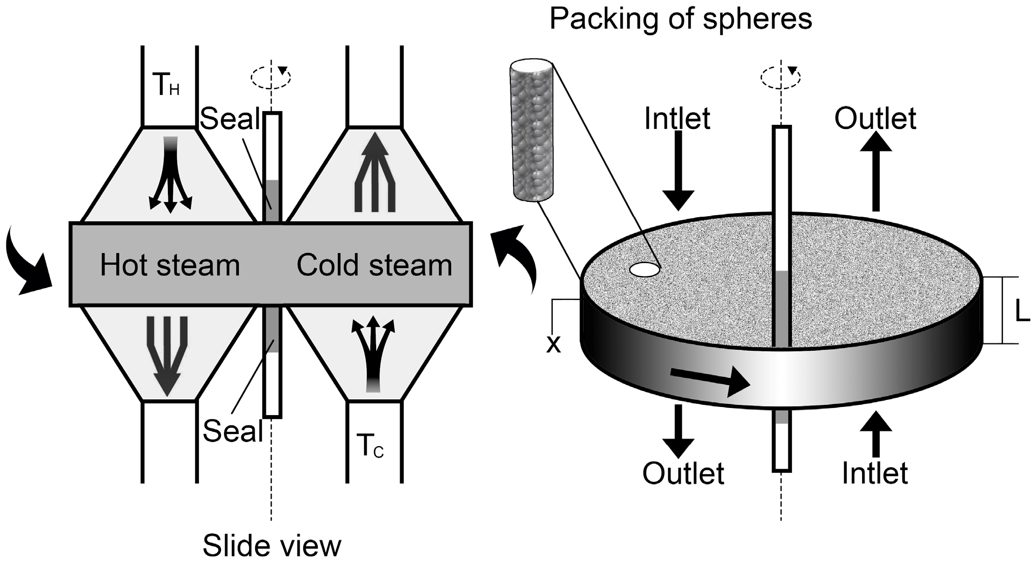
Figure 4.
A fixed-plate heat exchanger [7].
Figure 4.
A fixed-plate heat exchanger [7].

Figure 5.
Graph results for an air-to-air enthalpy heat exchanger [20].
Figure 5.
Graph results for an air-to-air enthalpy heat exchanger [20].
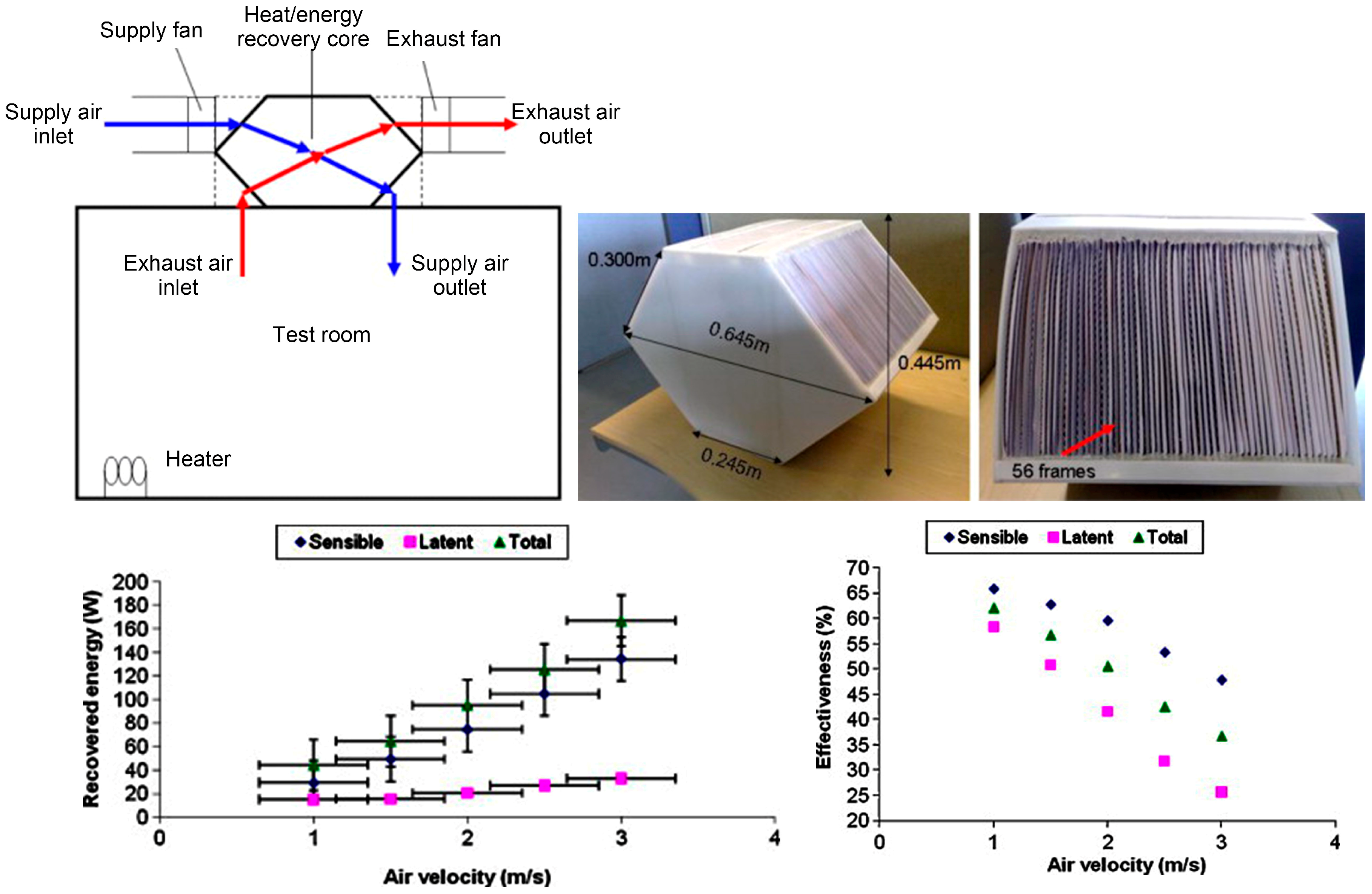
Figure 6.
Z-flow fixed-plate heat exchanger (HE) built using porous membrane material [21].
Figure 6.
Z-flow fixed-plate heat exchanger (HE) built using porous membrane material [21].
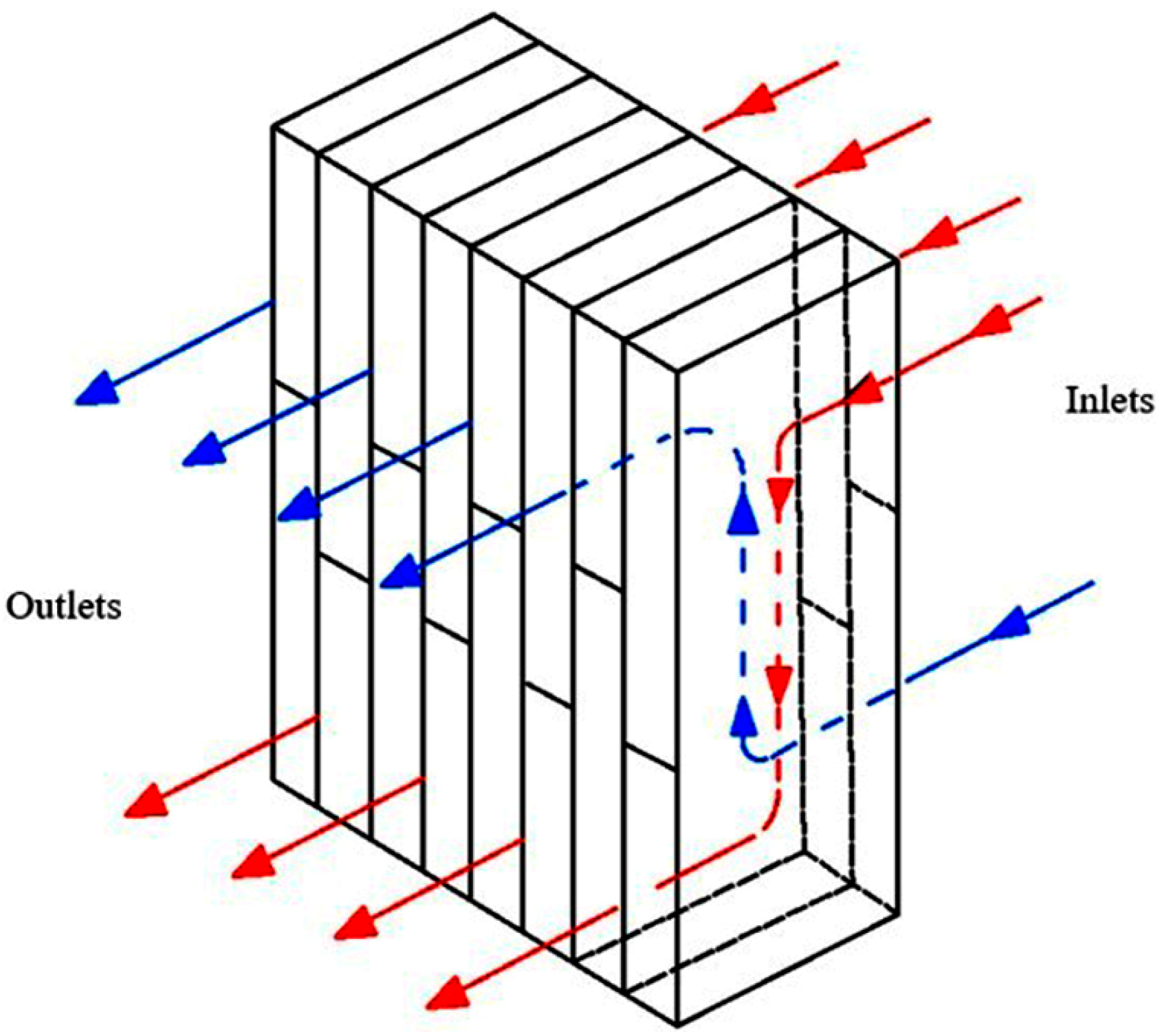
Figure 7.
Heat pipe heat exchanger in an air conditioning system and graphs of effects under different conditions on effectiveness [36].
Figure 7.
Heat pipe heat exchanger in an air conditioning system and graphs of effects under different conditions on effectiveness [36].

Figure 8.
Schematic representation of a micro-heat pipe recovery system [39].
Figure 8.
Schematic representation of a micro-heat pipe recovery system [39].
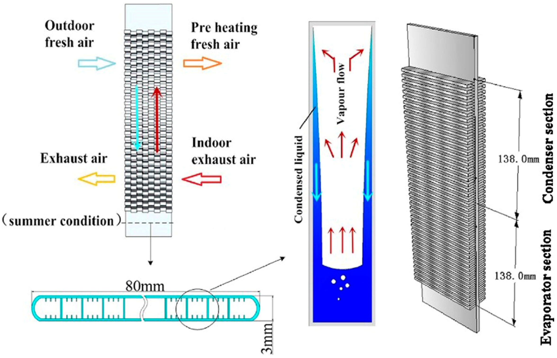
Figure 9.
The working principles of run-around heat recovery [7].
Figure 9.
The working principles of run-around heat recovery [7].
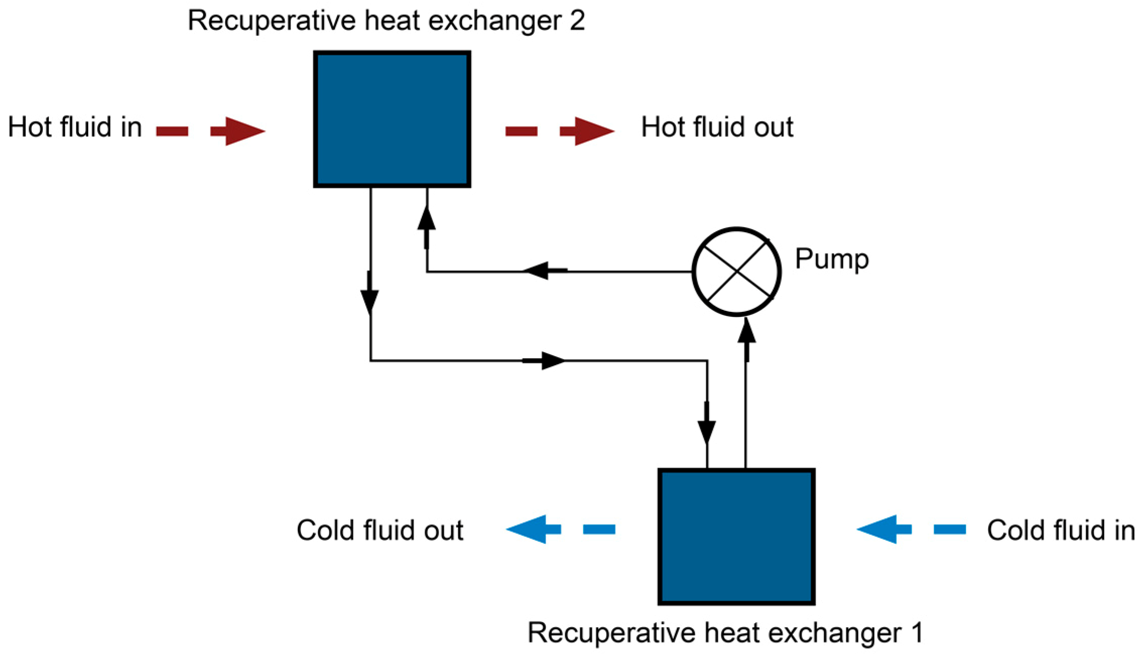
Figure 10.
Heat recovery system research article distribution.
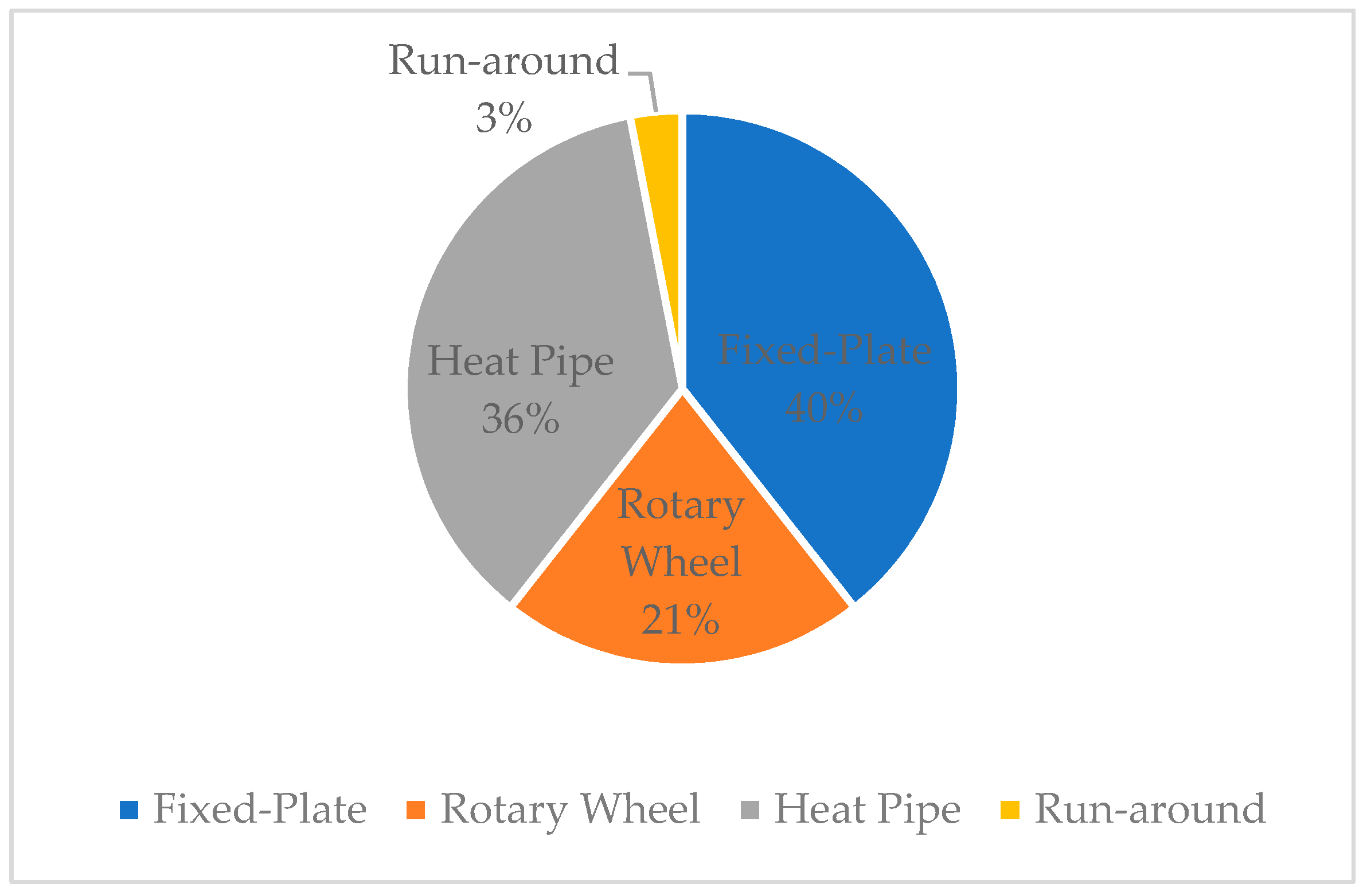
Figure 11.
Arrangement of the three heat exchangers [44].
Figure 11.
Arrangement of the three heat exchangers [44].

Figure 12.
Schematic representation of the plastic rotary wheel system [45].
Figure 12.
Schematic representation of the plastic rotary wheel system [45].

Figure 13.
Facade system with (a) counter flow heat recovery and (b) regenerative heat recovery [46].
Figure 13.
Facade system with (a) counter flow heat recovery and (b) regenerative heat recovery [46].
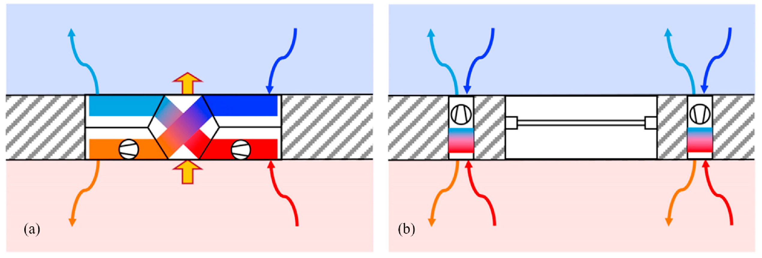
Figure 14.
Temperature monitoring during testing [47].
Figure 14.
Temperature monitoring during testing [47].

Table 1.
A comparison of the four types of heat recovery systems based on their thermal performance.
Table 1.
A comparison of the four types of heat recovery systems based on their thermal performance.
| Types of Heat Recovery | Rotary Wheel | Fixed-Plate | Heat Pipe | Run-Around |
|---|---|---|---|---|
| Main airflow arrangements | Counter flow, parallel flow | Cross flow, counter flow, parallel flow | Counter flow, parallel flow | N/A |
| Typical efficiency | Above 80% | 50~80% | 45~55% | 45~65% |
| Air speed (m/s) | 2.5~5 | 0.5~5 | 2~4 | 1.5~3 |
| Air pressure (Pa) | 100~170 | 25~370 | 100~500 | 100~500 |
| Temperature range (°C) | −60~800 | −60~800 | −40~35 | −45~500 |
| Advantages [7] | High efficiency, compact equipment, potential to recover sensible and latent heat. | Compact, relatively high heat transfer coefficient, no cross contamination, easy maintenance, can be coupled with counter-current flow which enables the production of closed-temperature differences, capable of recovering sensible and latent heat. | Fixed components, no extra power supply, high reliability, separate air duct, compact, suitable for naturally ventilated building, fully reversible, easy maintenance but only capable of recovering sensible heat. | Air ducts can be located side by side, ducts can be physically separated, no cross contamination, only capable of recovering sensible heat. |
Table 2.
A summary of heat recovery systems integrated into building components.
| Building Component | Images | Research Methodology | Key Features | Outcomes | Economic Analysis | Reference |
|---|---|---|---|---|---|---|
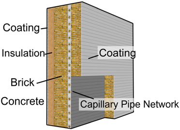
| Building wall | 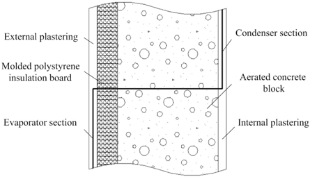 | Experimental investigation with 1720 mm × 1720 mm wall implanted with heat pipes (WIHP) and theoretical analysis | A new type of passive solar utilization technology; WIHP; different direction facing wall according to the located regions. | Application of the integration could reduce heat loss by more than 14.47% in winter. | NA | [48,49] |
 | MATLAB based simulation | Multilayer wall with capillary pipe network; significantly reduces building load; three locations for heat pipes including external, middle, and internal. | The wall could help save power energy from 2 W to 39 W with variation in outdoor air temperature depending on the season. | NA | [50] | |
 | TRNSYS software simulation | A pipe-embedded wall integrated with ground source-coupled heat exchanger; multi-criteria system design. | Using the same number of ground source-coupled heat exchangers (GDHE) the system could achieve over 30% energy savings in hot summer and cold winter climates. | NA | [51] | |
| Roof | 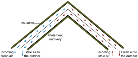 | Experimental investigation with a real-scale test house | A plate-type heat exchanger parallel-flow arrangement under roof application; recovers waste heat; preheats fresh air using stale air. | Heat recovery efficiency was found to be around 89%. The coefficient of its thermal performance is 4.5. | Relatively low cost of polycarbonate sheet-based roof type heat recovery panel, about €14.31/m2. | [52] |
| Wind tower | 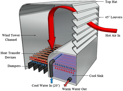 | CFD software simulation | A cooling wind tower incorporating heat pipe technology and cool sink; passive cooling system. | System can cool down air flow up to 12 °C, and at lower weed speeds (1–2 m/s), it can reduce the temperature significantly. | NA | [53,54] |
 | CFD software simulation and experimental investigation (1:10 scale experimental platform) | Heat pipes integrated into a multi-directional wind tower; recovers exhaust heat. | The application of the system can heat the supply air by up to 4.5 °C. In addition, the heat pipes can slow down the air supply rates by up to 8–17%. | NA | [55] | |
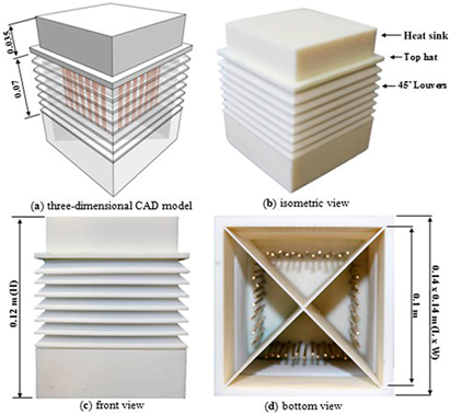
 (Redrawn by authors) (Redrawn by authors) | Experimental investigation using a large-scale chamber (3 m × 3 m × 5.6 m) with a wind catcher unit (0.7 m× 3.2 m × 0.45 m) | Integrated system with heat recovery and wind catcher; helps to assist air flow. | The combination system can cool down the inlet air temperature up to 0.9–1.8 °C. The heat exchange rate of the unit varies from 50% to 70% with different air flow velocities, which range from 1.2 to 3.1 m/s. | NA | [56] |
NA: Not available.
Table 3.
A summary of different types of heat exchangers with dehumidification systems.
| Type | Images | Key Features | Research Methodology | Results | Climate Conditions | Reference |
|---|---|---|---|---|---|---|
| Rotary desiccant wheel |  | Rotary wheel with polymer composite desiccant, sandwiched between the condenser and evaporator section of a heat pump with air channels | Laboratory experiment | Moisture removal capacity can achieve 7 g/kg. The desiccant wheel-heat pump system can decrease relative humidity from 59% to 45% and cool down the air from 32 °C to 29 °C during testing. | Humid subtropical climate | [60] |
 | Rotary desiccant wheel with passive ventilation, coated in silica gel particles | Laboratory experiment and CFD simulation | The model can achieve 55% of airflow dehumidification with lower regeneration air temperature and a lower pressure drop. | Temperate marine climate | [59] | |
 (Redrawn by authors) (Redrawn by authors) | Periodic total rotary heat recovery with polymer/alumina composite desiccant | Laboratory experiment | Silica gel and active alumina desiccant material can achieve high moisture removal, 2.1 g/kg and 1.7 g/kg, at regenerating temperatures of 40 °C and 25 °C, respectively. | Humid subtropical climate | [66] | |
 | Heat pump-driven two-stage desiccant wheel system | Mathematical model and laboratory experiment | The COP was calculated as 5.5 under summer conditions with a supply air humidity ratio of 10 g/kg. | Humid continental climate | [63] | |
 | Internally cooled 64% desiccant-coated wheel with heat exchanger | Laboratory experiment | The overall cooling capacity can increase by 64% and the EER by 21% with this model compared to those using an adiabatic desiccant wheel. | Humid subtropical climate | [62] | |
 | Desiccant wheel using humidity swing adsorption (HSA) | Theoretical study and laboratory experiment | The unit can achieve a temperature rise of up to 9.4 °C with an adsorption-to-regeneration air ratio of 1:2 and 8 rph rotary speed. | Humid continental climate | [61] | |
| Fixed-plate | 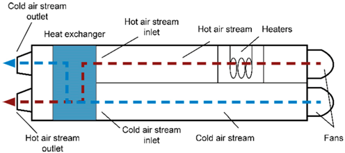 | Membrane heat exchanger using Kraft paper to transfer heat and moisture, assisting heating, ventilation, and air conditioning (HVAC) system. | Laboratory experiment and HPRate software analysis | The unit can help save up to 8% of annual energy consumption in hot and humid climates. | Humid subtropical climate | [21] |
 | Novel quasi-counter-flow membrane energy exchanger | Theoretical calculation and laboratory experiment | Under cold conditions, the unit can obtain 88.5–94.5% sensible effectiveness and 73.7–83.5% latent effectiveness with supply air temperature ranging from −4 to 10 °C. | Cold climate | [64] | |
 | Heat exchanger with asymmetric composite membranes | Mathematical model (outdoor relative humidity range 45%−90%) | For cooling, increasing outdoor relative humidity will cause decreased sensible heat transfer efficiency and increased latent heat transfer efficiency. For heating with outdoor relative humidity below 60%, a higher relative humidity (RH) rate will cause a slightly increased latent effectiveness while also producing a rather stable and sensible effectiveness. | NA | [67] | |
| Desiccant-coated heat exchanger |  | Desiccant-coated heat exchanger, desiccant cooling system | Mathematical model | Under simulated conditions, the lowest humidity ratio of supply air decreases from about 9.5 g/kg to 8 g/kg. The cooling capacity of the model increased by 30% compared with other desiccant-coated heat recovery systems without self-cooled recovery. | Humid subtropical climate | [68] |
 | Fin-tube heat exchanger with silica gel coating | Outdoor experiment investigation | The average moisture removal rate is 5.3 g/kg and the average thermal COP was calculated as being 0.34. | Humid subtropical climate | [69] | |
 | Solid desiccant-coated heat exchanger | Outdoor experiment investigation | The average moisture removal rate was 8 g/kg and the thermal COP was calculated as being 1.2. | Humid subtropical climate | [70] |
NA: Not available.
Table 4.
Heat recovery systems integrated with thermoelectric (TE) modules.
| Type | Images | Extent of Study | Research Methodology/Software | Outcomes | Economic Analysis | Suggestions | Reference |
|---|---|---|---|---|---|---|---|
| Fixed-plate |  | Theoretical analysis | Mathematical model including cost-performance model | By controlling operating variables, including thermoelectric numbers, filling factors, length of P-N legs, couple numbers of thermoelectric cooler (TEC), and overall thermal conductance, separately, the COP of the system varies from 2.18 to 4.37. | Under the optimal parametric conditions, the operating cost of the heat exchanger with thermoelectric module (HE-TE) system is lower than 0.02 $/kWh. | Further study is needed to test the feasibility of cost-performance conditions when multiple TECs are applied. | [71] |
 | Experimental investigation | Establish an experimental platform | This novel system can achieve overall coefficients of cooling and heating of about 50.6% and 57.9%, respectively, under optimal operating current and voltage. | NA | Phase change material (PCM) could be considered as the thermal energy storage of the solar-driven exhaust air thermoelectric heat pump recovery (SDEATHP) system to balance the cooling or heating needs of fresh air handling. | [72] | |
 | Experimental investigation | Laboratory conditions and MATLAB mathematic model | The finned heat sink with thermoelectric units has relatively poor output performance compared to the heat pipe with TE units. | Heat exchanger cost is $15.12/(W/K). | [73] | ||
| Heat pipe |  | Theoretical analysis and experimental investigation | Theoretical model using effectiveness-NTU (number of transfer unit) method and laboratory scale with two separate airducts (170 mm × 160 mm) | With increasing air flow velocity, the heat recovery efficiency increased from 67.9% to 72.4%. | N/A | [74] | |
 | Experimental investigation | Laboratory condition and mathematic model | The heat pipe combined with the thermoelectric unit cooling method shows better output performance compared to that of the heat sink. | Heat exchanger cost is $10.67/(W/K). | [73] |
NA: Not available. P: p-type semiconductor; N: n-type semiconductor.
© 2019 by the authors. Licensee MDPI, Basel, Switzerland. This article is an open access article distributed under the terms and conditions of the Creative Commons Attribution (CC BY) license (http://creativecommons.org/licenses/by/4.0/).
Share and Cite
MDPI and ACS Style
Xu, Q.; Riffat, S.; Zhang, S. Review of Heat Recovery Technologies for Building Applications. Energies 2019, 12, 1285. https://doi.org/10.3390/en12071285
AMA Style
Xu Q, Riffat S, Zhang S. Review of Heat Recovery Technologies for Building Applications. Energies. 2019; 12(7):1285. https://doi.org/10.3390/en12071285
Chicago/Turabian StyleXu, Qi, Saffa Riffat, and Shihao Zhang. 2019. "Review of Heat Recovery Technologies for Building Applications" Energies 12, no. 7: 1285. https://doi.org/10.3390/en12071285
Note that from the first issue of 2016, this journal uses article numbers instead of page numbers. See further details here.