A Review of Design Considerations of Centrifugal Pump Capability for Handling Inlet Gas-Liquid Two-Phase Flows
by
 , ,
, ,
Qifeng Jiang
1 ,
,
Yaguang Heng
1,*,
Xiaobing Liu
1,
Weibin Zhang
1,
Gérard Bois
2,* and
Qiaorui Si
3 1
Key Laboratory of Fluid and Power Machinery, Xihua University, No. 999 Jinzhou road, Jinniu District, Chengdu 610039, China
2
LMFL, FRE CNRS 3723, ENSAM, 8 Boulevard Louis XIV, 59046 Lille CEDEX, France
3
National Research Center of Pumps, Jiangsu University, Zhenjiang 212013, China
*
Authors to whom correspondence should be addressed.
Energies 2019, 12(6), 1078; https://doi.org/10.3390/en12061078
Submission received: 19 February 2019
/
Revised: 14 March 2019
/
Accepted: 15 March 2019
/
Published: 20 March 2019
Abstract
:Most of the pumps working under two phase flows conditions are used in petroleum industry applications, like electrical submersible pumps (ESP) for hydrocarbon fluids, in chemistry, nuclear industries and in agriculture for irrigation purposes as well. Two-phase flows always deteriorate overall pump performances compared with single flow conditions. Several papers have been published aiming to understand flow physics and to model all the main mechanisms that govern gas pocket formation and surging phenomena. These mechanisms depend on the pump type, the impeller geometry, the rotational speed, design and off-design liquid flow rate conditions, the volumetric gas fraction, the fluid properties and the inlet pressure. In the present paper, a review on two phase performances from various centrifugal pumps designs is presented, mainly based on experimental results. The main focus is devoted to detect the significant geometrical parameters that: (1) Modify the pump head degradation level under bubbly flow regime assumption; (2) Allow single stage centrifugal pumps keep working under two-phase flow conditions with high inlet void fraction values before pump shut down, whatever the pump performance degradations and liquid production rates should be. Because most of the published experimental studies are performed on dedicated laboratory centrifugal pump models, most of the present review is based on air-water mixtures as the working fluid with inlet pressures close to atmospheric conditions. The following review supposes that gas phase is considered as a non-condensable perfect gas, while the liquid phase is incompressible. Both phases are isolated from external conditions: neither mass nor heat transfer take place between the phases.
1. Introduction
Pump performance always decreases under two-phase flow conditions compared to single-phase ones. The degradation level depends on the pump’s specific speed, local geometry, fluid physical properties and thermal conditions. Axial flow machines are able to work with high void fraction values compared with centrifugal pumps. With increasing inlet gas void fraction, the performance of centrifugal pumps first deteriorates gradually, until the modification of the flow mixture pattern seriously affects the safe and stable operation of the pump itself and consequently the whole system.
The modification of two-phase flow patterns is driven by separation effects due to blade to blade pressure gradients as well as the Coriolis acceleration, coupled with additional strong radial pressure gradients due to centrifugal forces and local deceleration (Gülich [1]). These effects may be accentuated and reinforced in the axial-to-radial meridional inlet part of pump, because liquid is forced towards the hub, resulting in gas accumulation near the tip radius of the impeller eye. Inside the impeller blade to blade passage, close to the first throat area, gas particles move towards the suction side due to buoyancy effects. Further downstream, due to Coriolis force effects, liquid phase tends to be shifted towards the pressure side and so, flow pattern mixture may not remain in a bubbly flow situation. The two-phase flow pattern is thus more and more complicated to be correctly described and understood for off design conditions when incidence and stronger three dimensional effects take place. For increasing values of local void fraction, gas streamlines tend to be more and more shifted towards blade pressure surface close to the impeller trailing edge. As a consequence, it is still quite difficult to elaborate performing numerical models (using analytical and/or 3D CFD approaches) able to correctly describe and evaluate pump performance modifications. This is the reason why, flow visualization techniques are still interesting to be performed in order to understand local flow patterns and propose analytical and numerical models adaptations.
In 1974, Murakami and Minemura [2,3] presented what can be considered as the first and most basic important work on the effects of entrained air on the performance of a centrifugal pump. They associated pump performance modifications with two-phase flow patterns inside the impeller and proposed a first approach for pump head drop evaluation. Many other publications add information about bubble’s location and gas pocket formation such as Patel and Runstadler [4] and Kim et al. [5], who explained how slippage between phases leads to bubble agglomeration. Takemura et al. [6] associated large pressure gradients to bubble agglomeration as well. Local flow visualizations, bubble trajectories and size evaluations have been also performed, for example by Secoguchi et al. [7], Izturiz and Kenyery [8] and Barrios and Prado [9]. More recently, Kosyna et al. [10] measured impeller blade unsteady static pressure on the rotating impeller blade pressure and suction sides. An evaluation of local void fraction in two phase flows recently obtained by Schäfer et al. [11], using the X-ray tomography technique, also detected a thin gas film on the pressure side for the first time. In addition, Stel [12] proposed a force analysis in order to track single bubble trajectories, based on a Lagrangian approach, including bubble size effects. This analysis, however, does not take into account bubble interactions. A complementary approach, incorporating indirect semi-empirical bubble size prediction effects, is also proposed by Zhu and Zhang [13]. These authors have also published a quite interesting and exhaustive review (Zhu and Zhang [14]), devoted to electrical submersible pumps. It provides a comprehensive literature overview on experimental studies and modelling capabilities and explains the analytical and numerical models prediction limitations of ESP performance under gas-liquid conditions. Most of two-phase flow existing model use semi-empirical laws that are only valid for each specific investigated case. However, there is still a lack of appropriate pump users’ design rules and limitation criteria for centrifugal pumps working under two-phase conditions. As noticed by Gamboa and Prado [15], studies that are not related to ESP pump arrangements, can be quite useful ones to give appropriate good understanding of basic phenomena.
In this respect, the main goal of this review paper is to examine all available pump geometries’ performances, and propose additional semi-empirical rules and guidelines in addition to those already proposed by Cappellino et al. [16]. In Section 2, a focus on conventional single stage centrifugal pump performance is first presented, with conventional backswept impeller shapes followed by a classical volute design (without inlet inducer device). In Section 3, non-conventional designs are analyzed, for which researchers tried to improve pump ability to work under two-phase flow conditions with unusual impeller blade shape combinations, whatever the overall performance degradations and liquid production rates might be. In the last section, considerations on different kinds of impeller design are proposed using a compilation of the best design rules found in the present review.
2. Conventional Centrifugal Impeller Pump Designs
Conventional centrifugal designs are related to design rules corresponding to specific speed Ωs range values between 0.3 and 1.0 (international unit system is used: ω in rad/s, Q in m3/s, H in meter) With:
and head coefficient values ψ around 0.4–0.5. with:
ψ = gH/(U2)2
The blade number is generally equal to five or seven, with the outlet blade angle being less than 30°. Global efficiency range, for single flow conditions and sufficiently high Reynolds number, is generally between 75 and 82% (see Gülich [1] for example).
The global efficiency is defined as:
where P is the shaft power. This shaft power is usually obtained using torque meter measurements multiplied by the angular velocity ω.
2.1. Pump Performance Curves
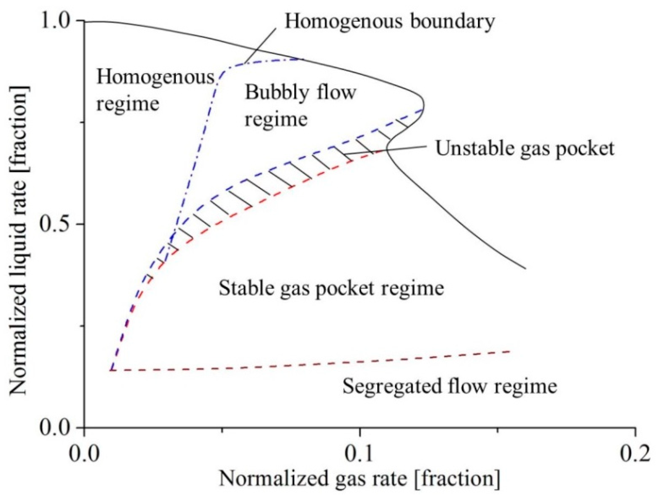
Estevam et al. [17], and Barrios [18] proposed using a mapping procedure defining separation lines between several regimes as shown in Figure 1 (the corresponding graph is derived from references [17] and [18]. Curve evolutions on the x and y coordinates mainly depend on pump specific speed and single or multistage configuration). This procedure uses normalized liquid versus gas rates. In addition, a second complementary chart gives head coefficient ratio curves versus inlet gas void fractions. The present review prefers the second form, because information about how liquid flow rate varies with inlet void fraction is unfortunately often not available in many papers.
Pump head coefficient ratio ψ*tp = ψtp/ψ0, is defined as the actual two-phase head coefficient ψtp divided by the head coefficient ψ0 obtained for liquid single phase.
2.2. Flow Visualization
As already pointed out in the Introduction, flow visualization techniques combined with measured pump performance results help to get better understanding of flow patterns inside centrifugal impellers. In a recent publication, Shao et al. [19], presented a classification on flow patterns inside the inlet tube, impeller and volute using high speed photography up to critical inlet void gas fraction for rated rotational speed of 1450 pm and initial volume liquid flow rates of 25 m3/h. In addition, they gave some more details on bubble movements. The results of these visualizations are quite similar to those obtained by Verde et al. [20], for an ESP case. These recent contributions confirm the main assumptions that support the initial works proposed by Murakami and Minemura [2,3] for pump performance modelling with gas-liquid flow pattern inside a centrifugal impeller. The following classification is now widely adopted; four degradation sequences are defined related to increasing inlet void fraction values:
- (1)
- A homogeneous flow regime exists when the local void fraction is low (from 0% to 4%) inside the blade passage. Liquid flow rate almost remains the same with a slight decrease compared to the initial pump liquid flow rate. Isolated bubbles follow the same streamlines as the liquid ones with quasi-similar velocities. Slip velocity between phases are quite low and drag losses between phases can be considered negligible. When the local void fraction increases, the flow pattern still corresponds to a bubbly flow regime but with higher concentration of isolated bigger bubbles (due to local pressure gradients), almost equally distributed inside the flow passage. Slip velocity increases slightly, resulting in an increase of losses and a continuous reduction of liquid flow rate.
- (2)
- When bubbles start to agglomerate (due to increasing inlet void fraction, bubble collisions and force actions already discussed in Section 1), slip effects between phases become stronger and are not negligible any more in some parts of the impeller passage.
- (3)
- With further increase of the void fraction, the flow regime evolves to the so-called “gas pocket flow” that may occupy a large portion of the impeller passage generally close to the suction side just after the inlet throat area. This situation is generally unstable and corresponds to the starting point of sudden severe pump performance degradation. Part of the gas fraction is not transported any more with the liquid through pump outlet section and partially blocks the liquid flow rate. Thus, the pump liquid flow rate decreases more sharply. An explanation of such phenomena is given by the work proposed by Kosyna et al. [10] who measured the static pressure distribution along the blade impeller. They found that the difference between pressure and suction side tends to decrease in the first 40% of blade chord length resulting in a strong decrease of the blade force.
- (4)
- The combination of high inlet void fraction and small liquid flow rate leads to a phase separation inside the impeller passage, so the local void fraction may reach 100%. This corresponds to the “segregated” flow regime, the consequence of which results in pump gas-locking situation; the pump loses part or completely its ability to provide pressure and flow rate.
These sequences depend on the initial flow conditions of the pump and are mainly related to impeller designs. They might be different, for example, at lower rotational speeds than rated ones. These points are discussed further in another section of the present review.
2.3. Performance Curves
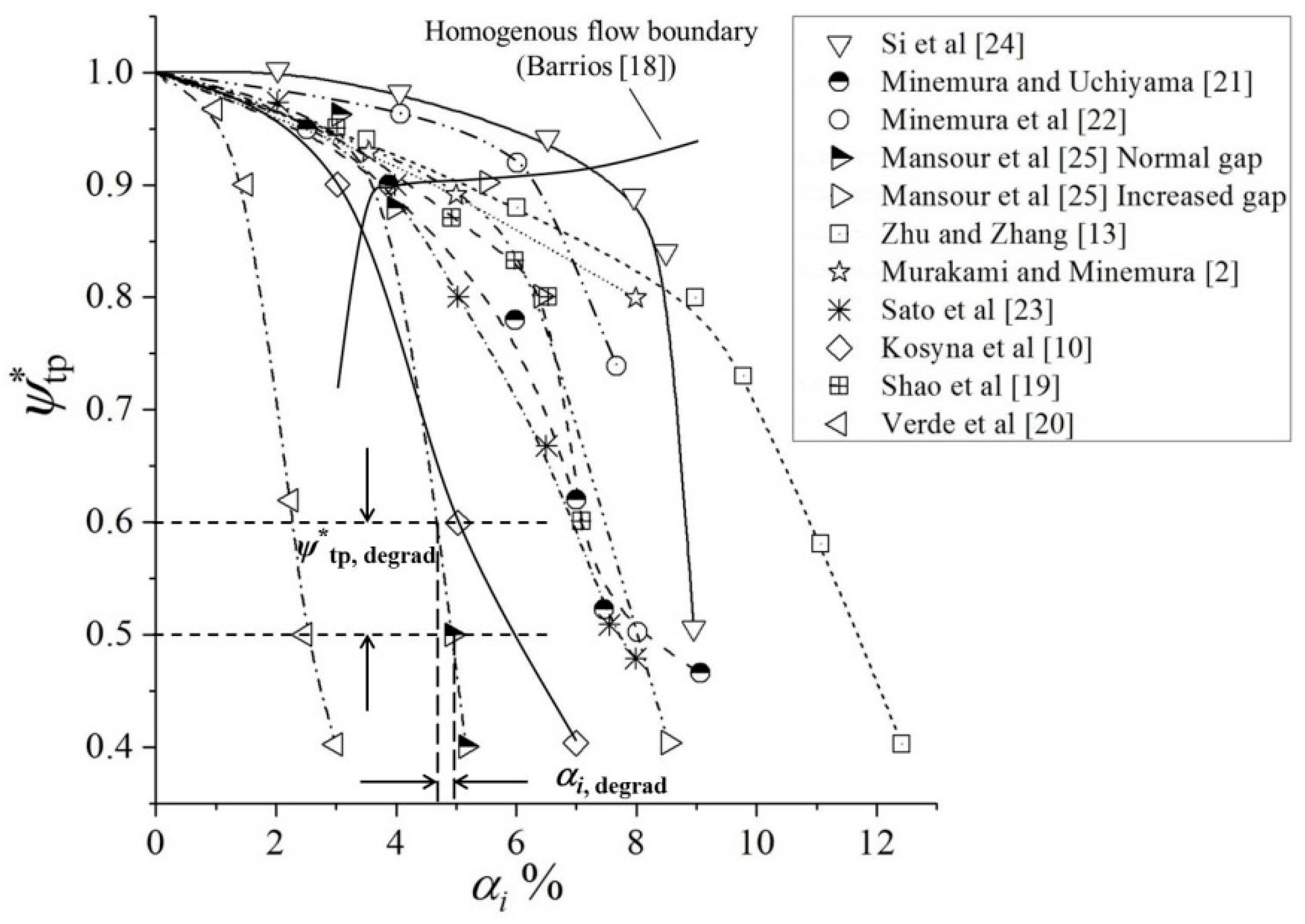
Figure 2 was specifically worked out by the present authors based on available open literature results listed in Table 1. It shows a compilation of pump performance degradation ratio ψ*tp versus inlet void fraction coming from each existing publication. These results have been chosen close to pump design conditions and for each rated rotational speed. Other relevant design parameters and flow conditions also appear in Table 1. For each case, a degradation coefficient ψ*degrad in the range of ψ*tp = 0.5–0.6 is arbitrary selected to compare all pump performances. The corresponding inlet void fraction value named as αi,degrad is determined from each curve. The way αi,degrad is graphically obtained is shown on Figure 2 by the dotted line as an example.
The accuracy of the values plotted in Figure 2 strongly depends on the quality of the figures that were found in each published paper. Consequently, the values of ψ*tp are given within an error band of ±2.5%. However, this does not affect the present analysis. Symbols that are plotted in Figure 2 are only used to follow each curve shapes’ fit and do not exclusively correspond to raw data points of each reference case.
Each head degradation ratio curve exhibits a sharp decrease after a specific critical value of αi, defined as αi,degrad. After this critical point, the flow is generally not considered as a homogenous mixture any more according to visualization results. A limiting curve is added in Figure 2, corresponding to homogeneous flow conditions (continuous line). This limiting curve has been already suggested by Barrios [18]. Before each sharp decrease, all curves generally present a negative slope evolution that depends on each pump design and flow conditions. Since centrifugal effects are important in the present specific pump category, rotational speed and flow coefficients are supposed to be important parameters for the analysis proposed hereafter.
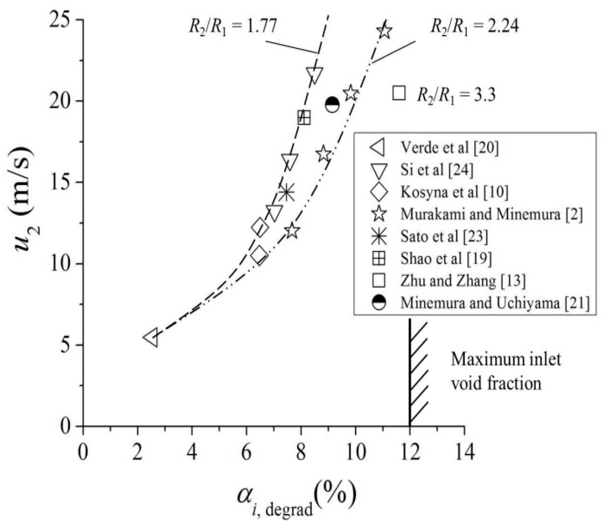
Consequently, a first empirical correlation between the inlet void fraction value αi,degrad and the impeller outlet rotational velocity (which includes outlet impeller radius and rotational speed) is given on the plot shown in Figure 3. As the impeller outlet speed increases, the inlet void fraction can be increased before causing severe degradation of the pump case. This has been qualitatively explained by Murakami and Minemura [2] due to the fact that impeller leading edges are able to cut inlet bubbles more easily into smaller sizes when rotational speed increases. This may also be associated to particular physical features called as “break-up effects” that can be found in some two-phase flows cases that are not studied in the present paper.
All pump geometries corresponding to a radius ratio R2/R1t between 2.0 and 2.5, show that a maximum value of 11% can be reached for αi,degrad. Two sets of performance results do not follow this general curve fit: they correspond to Si et al. [24], for which radius ratio is equal to 1.77, and to another case (Zhu and Zhang [13]), for which the impeller rotates with an higher speed (N = 3500 rpm with a radius ratio of 3.3) and is not followed by a volute, but by a vane diffuser. In addition, whatever the value of αi,degrad is, none of the pump’s designs are able to work for inlet void fraction values more than 12% for the best cases (depending on the radius ratio’s value). It can be concluded that maximum admissible inlet void fraction is strongly influenced by the outlet impeller rotational speed and radius ratio.
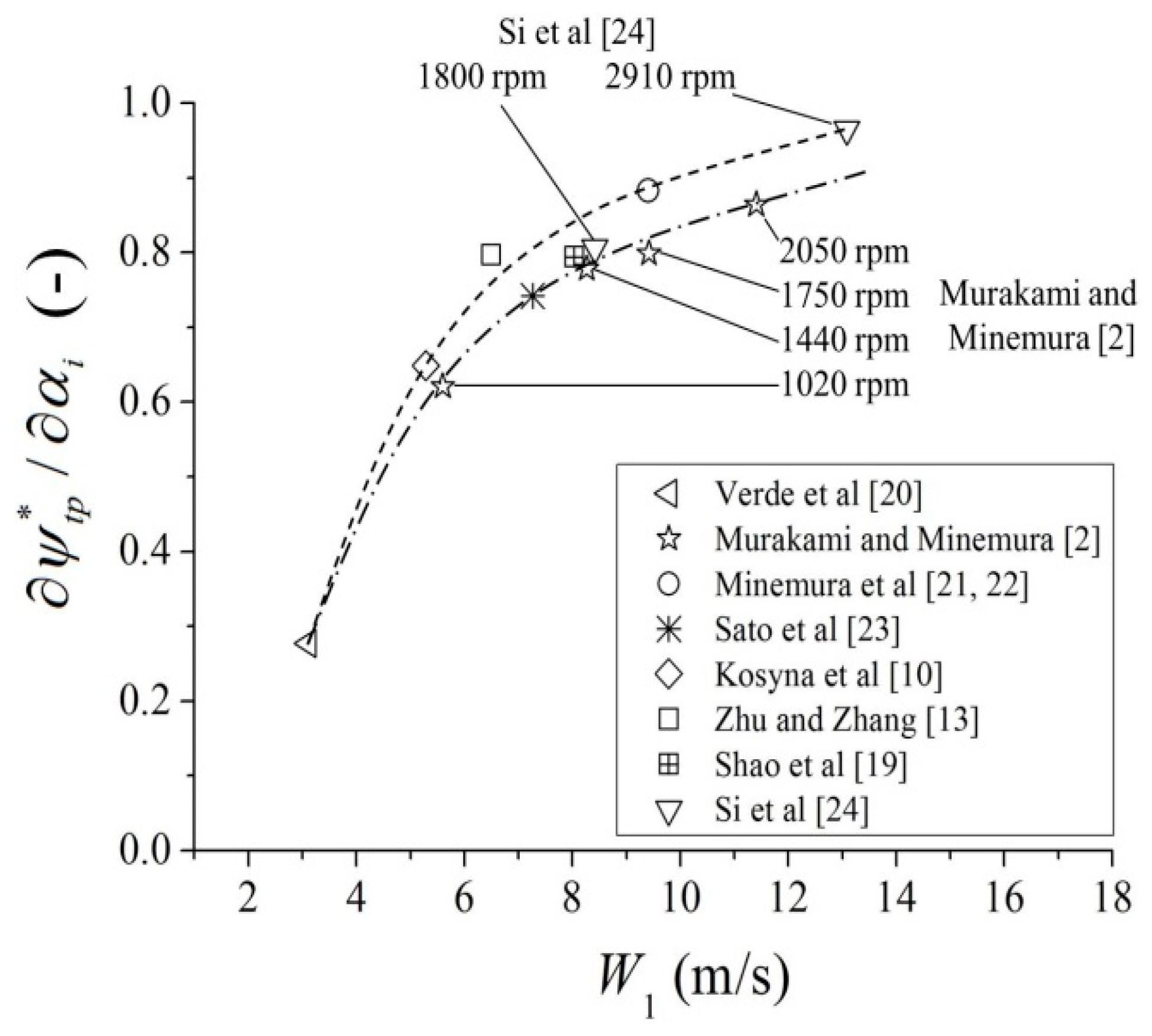
A second empirical correlation is proposed using the pump’s inlet relative velocity W1, which combines inlet rotational velocity U1 at design flow rate (assuming optimum incidence angle) and the mean slope curve of ψ*tp that can be deduced from each curve presented on Figure 2 which belongs to the homogeneous flow regime zone. The resulting curve is given in Figure 4. It also shows a remarkable correlation: the degradation level strongly depends on the inlet relative velocity and an asymptotic value of the slope (close to 1) is achieved when the relative inlet velocity reaches 14 m/s.
2.4. Effect of Rotational Speed for a Given Pump (Close to Nominal Pump Liquid Flow Coefficient)
In order to keep impeller inlet relative angle at a constant value, both rotational speed and flow rate must be considered, so that flow coefficient and consequently inlet flow relative angles remain constant.
Murakami and Minemura [2] first obtained results on the positive effect of rotational speed on a given pump geometry. Si et al. [24] also observed the same kind of results for different pump designs. In addition to the cutting effect of the blade leading edge proposed in the previous section, Zhu and Zhang [13], explain how increasing rotational speed modify volumetric average gas void fraction distribution inside the impeller passage towards impeller outlet section based on the bubble diameter prediction model they developed.
Results obtained by Murakami and Minemura [2] and Si et al. [24], already presented in the previous section for design rotational speeds, are also added on Figure 3 and Figure 4 (see additional information in Table 2). More analysis concerning combined effects of rotational speed and liquid flow rate, especially when the rotational speed decreases, can be found in Cui et al. [27]. Thus, for further research, it is suggested to perform a deeper analysis using the corresponding Reynold number based on inlet and/or outlet impeller radii.
Note that Shao et al. [19] do not find such an effect on rotational speed and conclude that, for the case they have investigated, rotational speed (below 1450 rpm) has no influence on the performance at the critical void fraction condition. Compared with other cases, this may be due to rather low values of rotational speeds combined with a quite high value of their radius ratio R2/R1t.
One particular aspect should also be investigated: when increasing the rotational speed, cavitation risks may occur. This must be checked in relation with NPSH recommended values at impeller inlet for each pump case future survey.
2.5. Effect of Flow Capacity-off-Design Conditions
The flow coefficient modifies performance degradation curves because of the incidence effects at the inlet blade section. Very often, a small increase (between 1 to 3%) of inlet void fraction leads to a better head coefficient for a slightly higher flow coefficient compared to nominal conditions. This is probably due to the fact that the impeller losses increases in such a way that the liquid flow rate decreases and tends to increase shock-less incidence angle value which is balanced when additional gas-liquid mixture volume rate is added. On the other hand, depending on the choice for shockless design incidence value, the curve degradation slope is more pronounced for lower flow rates than for higher ones. For lower flow rates, the pump rapidly tends to break-down conditions; for high flow rates surging may occur before large pump degradation. No evident correlation has been found for the present review.
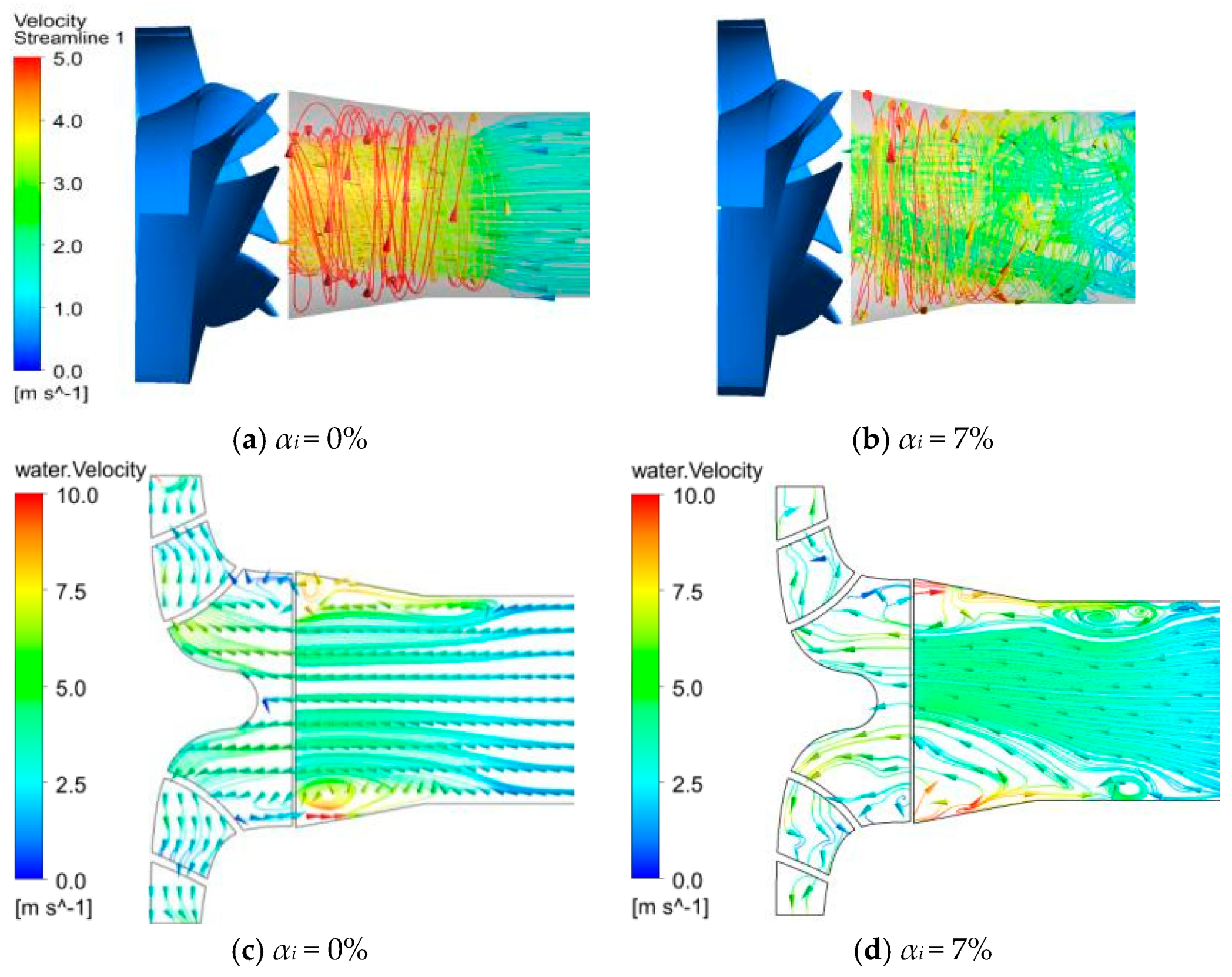
However one important point concerning off design conditions must be pointed out: when a constant flow coefficient is used, since liquid flow rate and rotational speed must vary accordingly. Si et al. [24] suggest that lower rotational speed and flow rate (keeping flow coefficient at a constant value), lead to a decrease of the inlet pipe mean velocity, so that transition from bubbly flow to plug or slug flow may occur before the pump inlet section. This means that such a transition can happen not only inside the impeller channels but far upstream in the incoming pipe, resulting in non-uniform and no more homogeneous inlet flow conditions. According to their analysis, all experimental results obtained for the two higher rotational speeds they used are in quite fair agreement with bubbly flow regime assumption (up to a certain value of αi around 7–8%). It is suggested that further works should consider inlet flow two-phase flow patterns in front of the impeller for a complete and better understanding in particular for off-design low flow rate conditions. The following example, illustrates that inlet streamlines may be quite different before pump impeller inlet section when inlet void fraction is modified (Figure 5a–d). These flow features has been obtained using CFD unsteady calculation extracted from Si et al. [28] for a flow coefficient lower than the nominal one
2.6. Theoretical Head Coefficient
An important result is also pointed out by Si et al. [24,28,29,30] concerning theoretical head coefficient curves obtained from the experimental overall pump test results they performed. Theoretical head coefficient is obtained from the conservation law of angular momentum applied in an impeller and also named as the “Euler Head”. It is expressed by the following relation (development can be found in several turbomachinery books; see also in Gülich [1] or Zhu and Zhang [14]).
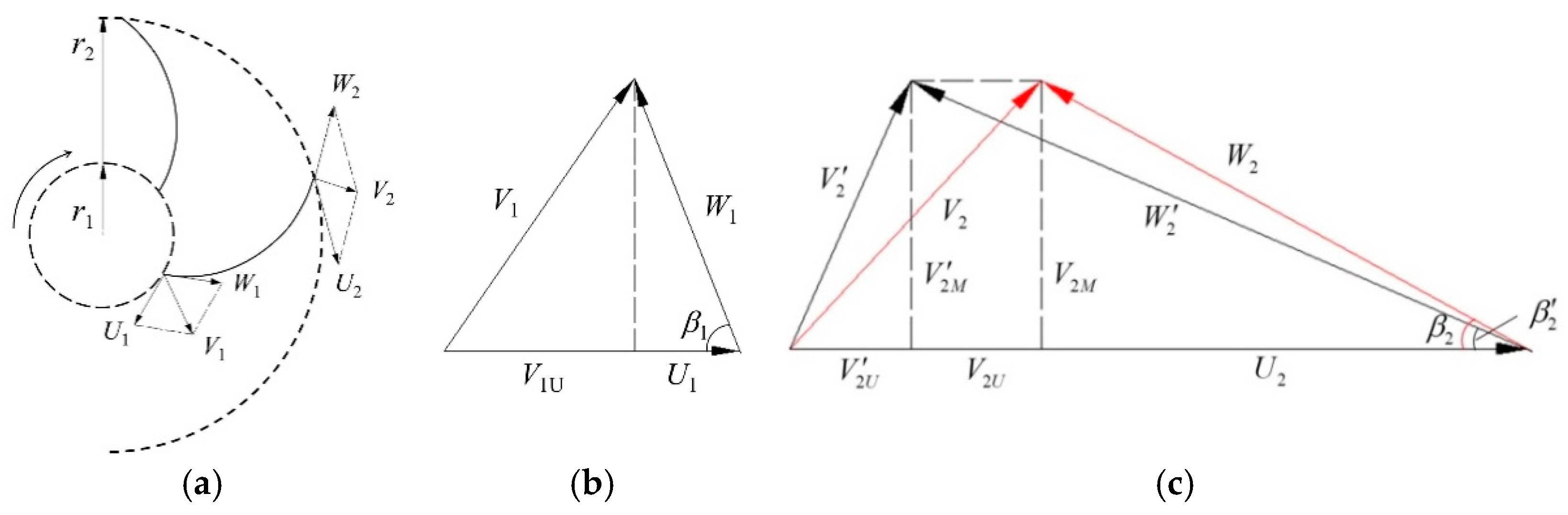
According to the ideal conservation law of angular momentum in rotating centrifugal pump, the Euler head (HE) can be expressed as (see Figure 6 for the definition of the variables):
After well-known developments, the simplified Euler head can be written as follow assuming no inlet impeller pre-swirl:
where r2 is the outlet radius of impeller, b is the channel meridional height.
Introducing theoretical head coefficient ψE = gHE/(u2)2, flow coefficient φ = Q/(2π·R2·b2·u2) with = (u2)2 in relation (5), one can obtained the following simple relation:
The corresponding curve, assuming that the relative outlet mean flow angle β2 does not depend on flow rate, is a straight line for which the value of the theoretical head coefficient is 1 for zero flow rate with a negative slope that depends on the outlet mean flow angle value β2.
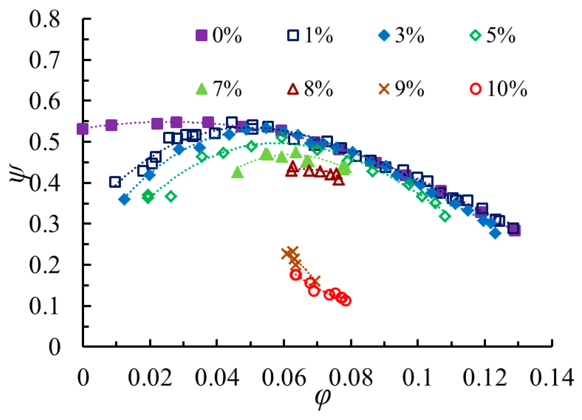
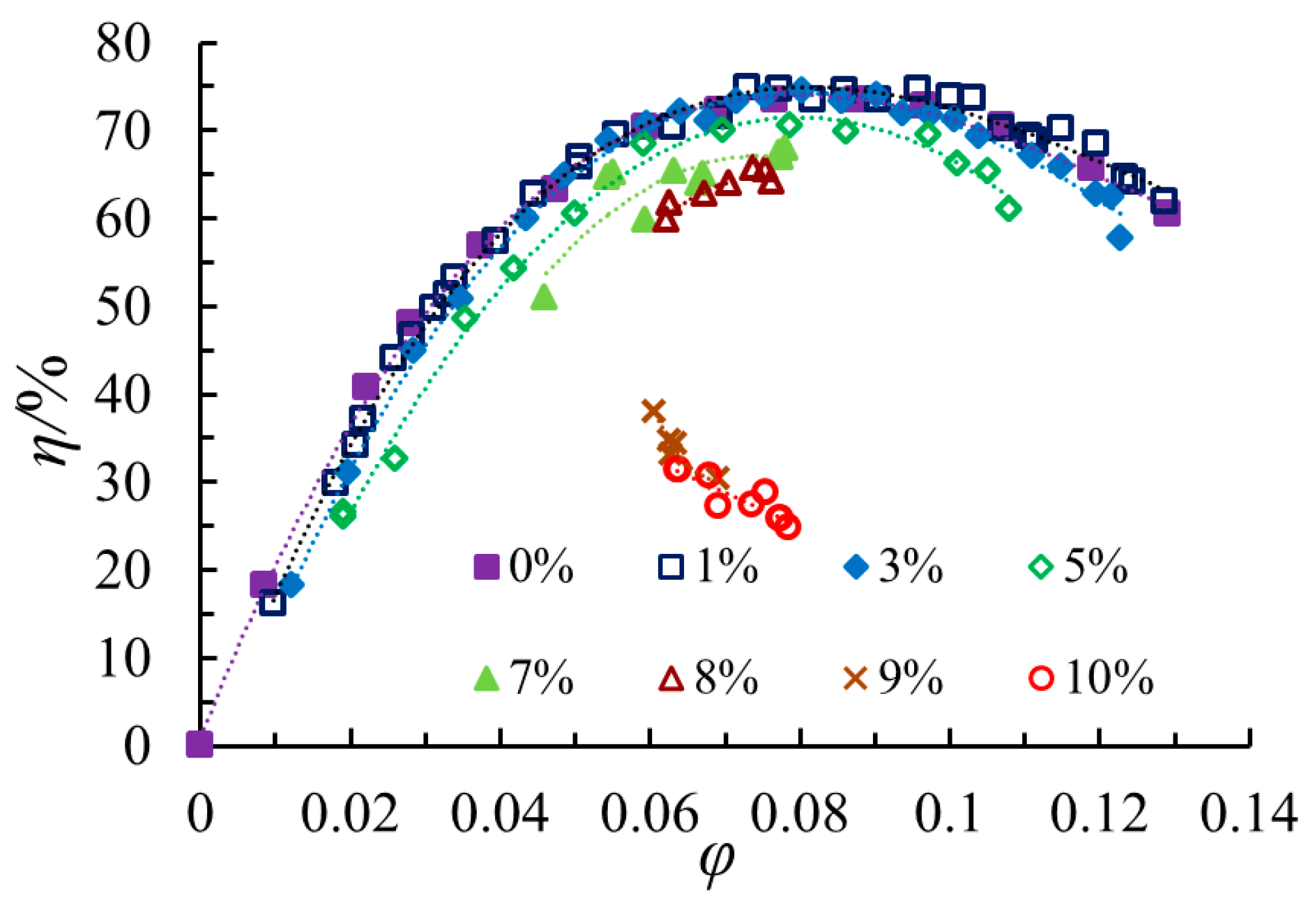
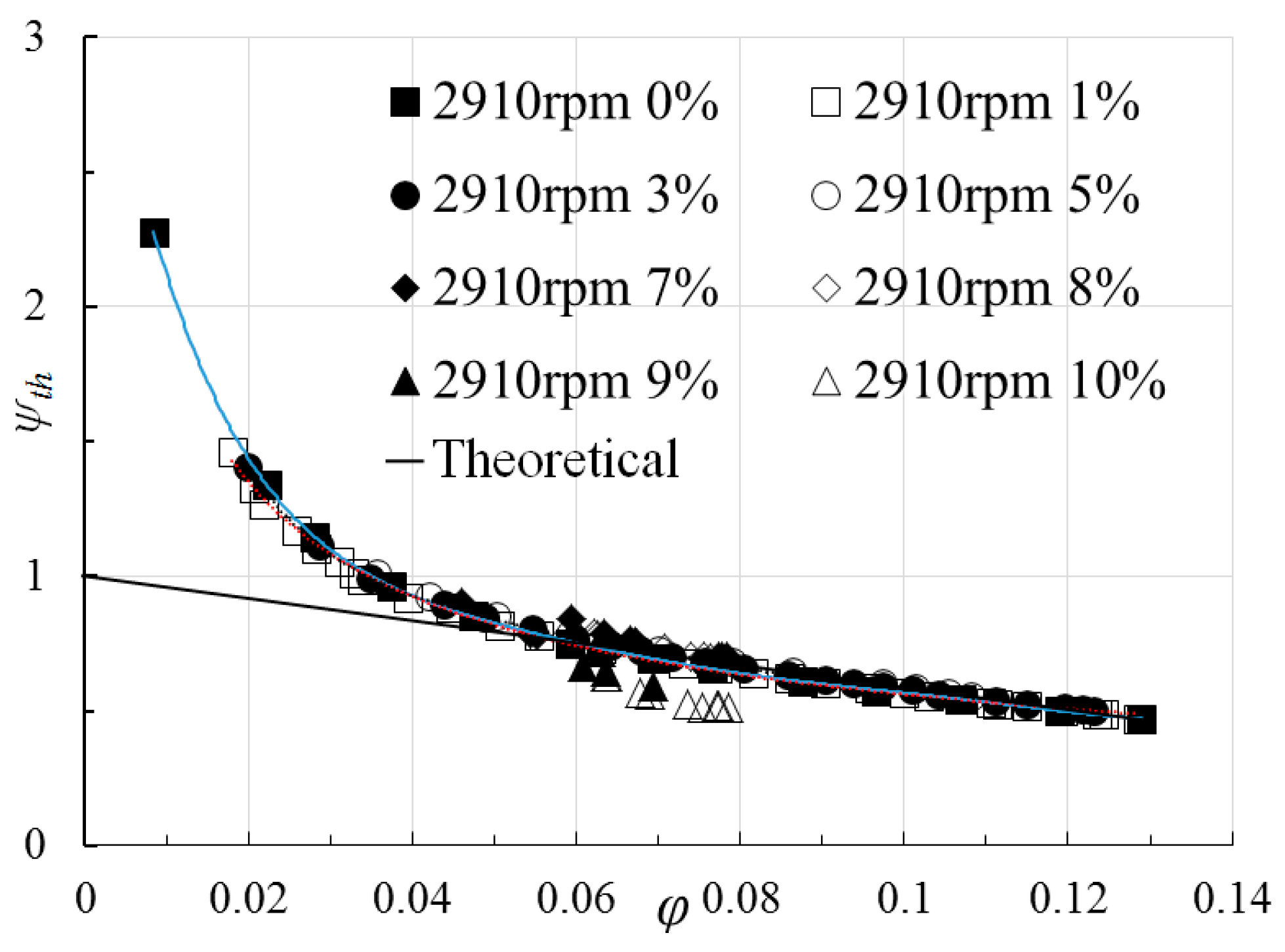
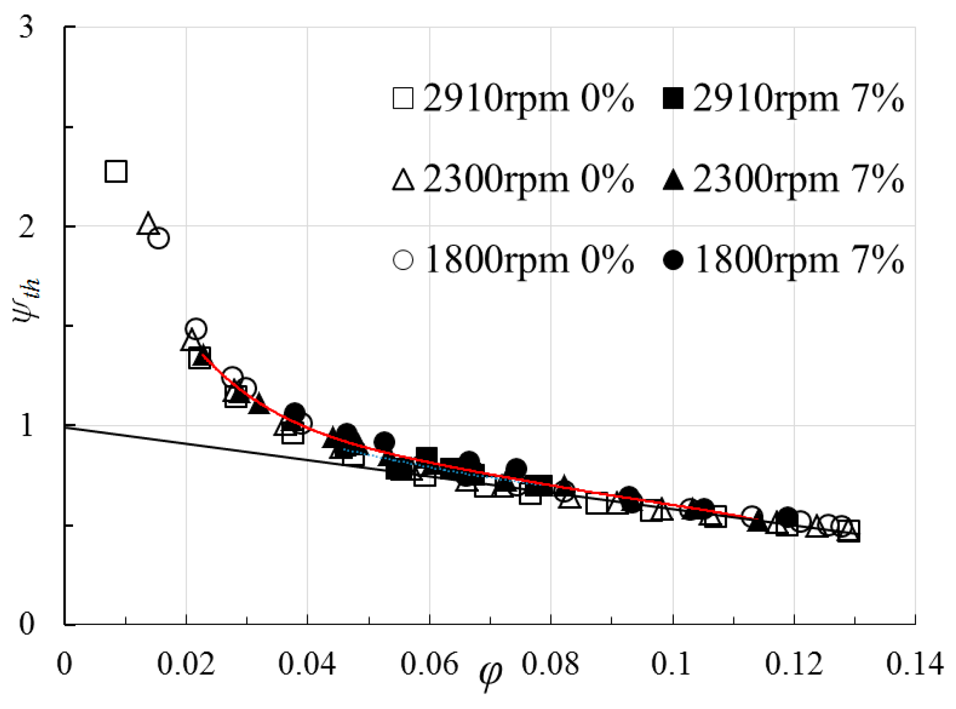
An example of experimental pressure coefficients and efficiencies versus flow coefficient is given in Figure 7 and Figure 8 obtained by Si et al. [24]). The deterioration effects on head coefficient and efficiency caused by increasing inlet void fraction values can be seen. The corresponding theoretical head evolutions obtained from torque measurements are shown in Figure 9 and Figure 10, respectively for several constant inlet void fractions at the rated rotational speed and for three different rotational speeds at a given inlet void fraction value of 7%. Figure 9 shows a remarkable result: a unique curve is obtained using theoretical two phase head and liquid flow coefficients up to an inlet void fraction value αi of 8% for all flow coefficients. For the two highest inlet void fractions of 9 and 10%, the values of theoretical head are smaller. This may result from a change on the two phase mean relative flow angle at the impeller outlet section or a bigger uncertainty in the head measurement due to flow instabilities that start to be quite important for such void fraction values. Figure 10 shows the theoretical head curves under αi = 0 and 7% for three different rotating speed of 2910 rpm, 2300 rpm, 1800 rpm. The unique curve remains exactly the same compared with Figure 9. This means that theoretical head is independent of fluid mixture pattern up to a maximum inlet void fraction of 8% for all flow coefficient ratio values whatever the rotational speed is. This result is quite usual for single phase conditions when the Reynolds number is sufficiently high, but never being checked for two phase flow conditions. This is an important result, since it validates all semi-empirical and one dimensional model assumptions that have been used for most of existing one dimensional approaches that can be found in literatures for conventional centrifugal pump geometries working under bubbly flow regime.
Secondly, the theoretical head coefficient curve corresponding to the simplified Euler relation ΨE = gHE/(u2)2, which is plotted as the straight full line on Figure 9 and Figure 10, exactly fits the experimental results for flow coefficients ratio higher than 0.6 (compared to the nominal flow coefficient of 0.09 for the present case). These results are usually obtained for single flow conditions, but never investigated in previous open literature papers for two-phase flow conditions. This contribution means that inlet recirculation and pre-swirl condition does not strongly depend on the inlet void fraction up to 8% and that disk friction losses are probably not modified inside hub and shroud centrifugal pump side chambers. Such an analysis should be performed for all existing cases from open literature results and in particular for unshrouded ones.
2.7. Number of Blades
In the second report of Murakami and Minemura [3], the blade number effect was investigated, using three, five and seven blades with unshrouded impellers. An increase of the number of blades from five to seven leads to an increase of the head deterioration slope, for αi higher than 7%. This is probably due to smaller throat area at pump inlet that locally modify the streamlines curvature associated with higher head loss due to bubble accumulation. However, for αi from 0 to 7%, degradation level is increasing when the number of blades decreases except the particular case of Z = 3 for which initial slope sign is positive (between 0 and 3%). Such a particular result is explained by Murakami et al. and is mainly related to the inlet impeller throat area which is located further downstream compared with the cases of larger blade numbers. This particular behavior has been also found by Si et al. [24]
2.8. Impeller Outlet Blade Angle
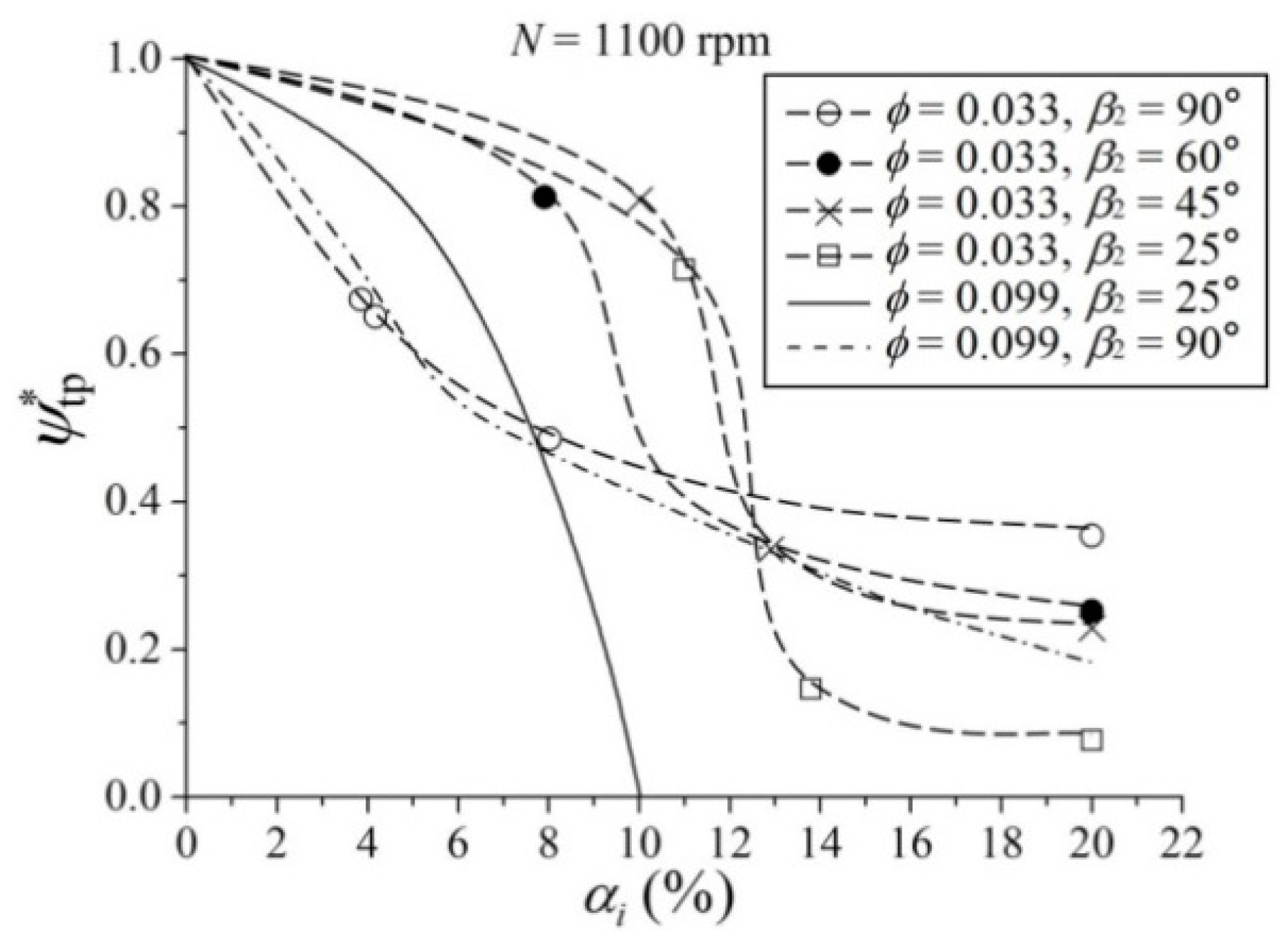
A set of five different outlet impeller blade angles have been tested by Sato et al. [23] from a “conventional” angle of 25° (already taken into account in previous section) up to 90° radial blade. All other geometrical parameters remain constant and are given in Table 3.
Figure 11 is adapted from the experiments they performed for two different flow coefficients, one close to nominal condition (φ = 0.099), and another for a lower one (φ = 0.033). It can be seen that the initial slope value of the degradation ratio ψ*tp near αi = 0 is strongly related to the impeller outlet angle value β2. The more β2 is increasing, the more the negative slope value increases. However, for impeller outlet angle values more than 40°, and despite strong performance degradation, pump was found to be able to lift two-phase mixtures up to 20%, especially at low liquid flow coefficients. None of conventional designs that are investigated in the present review reach such a relatively high values of inlet void fraction. Consequently, these particular blade shape designs are considered in Section 3, devoted to “particular pump designs”.
2.9. Tip Clearance Effects for Unshrouded Designs
In the case of semi-open impeller designs, the tip clearance gap allows the formation of strong vortex flows due to the difference between suction and pressure sides along the shroud part of the impeller. This vortex is transported along 3D flow streamlines and enhances phase mixing. As a result, relatively large values of impeller gap leads to better gas handling capability, even if overall pump performance is worse compared with shrouded impeller configuration. The recent results obtained by Mansour et al. [25,26], which are also reported on Figure 2, explain well how tip clearance prevents gas accumulation in specific region in the impeller passage. However, the corresponding pump performances still remains poor for αi > 9%.
2.10. Volutes
Up to now, two-phase flow pattern in volute was not deeply studied. To our knowledge, volute geometrical modifications are not proposed in open literature with respect to two-phase flows. Visualization has been recently performed by Shao et al. [19], showing that quasi-bubbly flow situations can be found in their volute just after the impeller outlet section whatever the two-phase mixture pattern is inside the impeller. In the external part of the volute, only water has been found because of higher local static pressure levels due to main flow deceleration. Since liquid flow rate is always diminishing with increasing αi, authors of the present paper suggest to study the influence of smaller size volutes, according to the fact that absolute flow angle at impeller outlet is always decreasing compared with single flow conditions.
3. Particular Impeller Pump Designs
In 1992, Cappellino et al. [16] studied what should be the appropriate choice of a centrifugal pump working respectively under low and high inlet void fractions, and suggested adding inducers in front of the impeller or to use vortex pump in order to increase pumps’ ability to work at higher inlet void fractions.
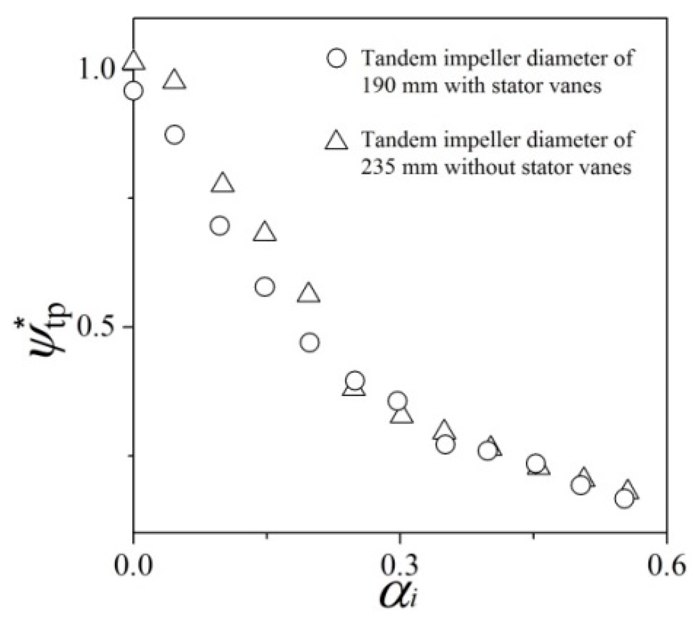
Concerning the present review, some particular pump designs are considered, still focusing on impeller design criteria. In the previous section, impeller designs using high blade relative outlet angle values (more than 60°) have been already presented. Within this respect additional research is also presented by Sato and Furukawa [31] for which movable blades were used. Successful impeller and vane diffuser specific sets of designs are achieved by the same research group (Furukawa et al. [32,33]). Some extensions are also proposed by Matsushita et al. ([34,35]) looking at possible application of similarity laws for such designs. They all presented interesting studies, developing different kind of tandem arrangement cascades and blades as shown in Figure 12. For this case, taken among other examples, the inner blade cascade is design with a 90° outlet blade angle; the outer blade cascade have higher outlet angle more than 90°. Two outlet radii (see Table 4), combined with two impeller blade heights are tested for different inlet void fractions.
Such an arrangement allows the pump to work with quite high values of inlet void fractions up to 60% at nominal flow coefficient and 50% for reduced one with rotational speeds between 1250 and 1500 rpm. They also pointed out that, for this particular design, beneficial effects of larger blade height and larger outlet impeller radius can be found. This last result is a confirmation of what has been found from the analysis based on the correlation illustrated by the plots in Figure 3. The tandem configuration developed by these authors prevents local gas accumulation and allows more mixing effects in the rotating vaneless part between the two cascades and tends to a redistribution of bubbly flow pattern that flows inside the second cascade arrangement with new inlet two-phase conditions. An example of the corresponding head coefficient variation versus inlet void fraction is given in Figure 13. It can be seen that this tandem arrangement makes the pump working with quite high inlet void fraction up to 50%. Another kind of tandem blades impeller design has been also proposed for multistage application by the so-called MVP pump studied in Marsis’ PhD thesis [36]. Both designs allow pumping higher inlet void fraction values compared with conventional designs
4. Other Design Considerations
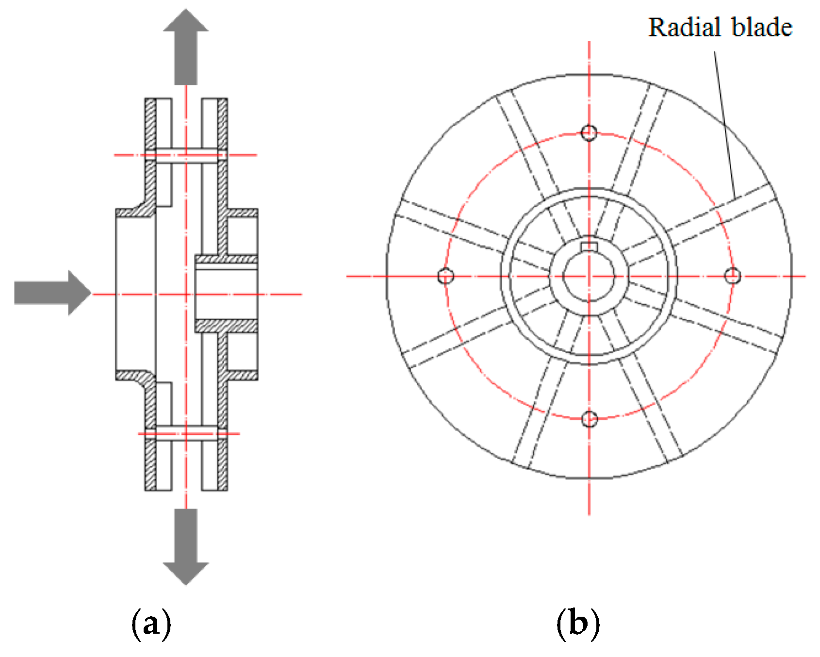
Considering all previous results of the present review, a combination of most of relevant parameters can be found using the concept of adapted disk flow pumps developed by the DiscfloTM Company for which a research report for single flow conditions is proposed by Yin [37]. This new impeller configuration (see Figure 14) adopts two combined radial blades, fixed on shroud and hub parallel plates, separated by a large clearance in the middle of the meridional passage. Such design can be considered as a kind of double vortex pump with high radius ratio. An equivalent configuration will be tested in the future by the present paper authors’ team in two phase flow conditions with several different blade inlet profile angle arrangements combined with single and double cascades according to Furukawa and Sato’s initial ideas.
5. Some Additional Considerations on Experimental Test Procedures
Because of flow pattern complexity inside the impeller and volute, it is still useful to perform experimental two phase flow studies. Some best practice experimental procedures are listed below based on several authors’ important recommendations for two-phase flow measurements in pumps and present paper authors experiences. A specific procedure is proposed by Mansour et al. [26], using a three step procedure in order to detect possible hysteresis effect due to air accumulation inside the impeller and built the two-phase mapping curves proposed by Estevam et al. [17] and Barrios [18].
Consequently, an ideal testing procedure should follow the sequences described below:
- (1)
- Start with single phase measurements for several flow rates and rotational speeds. Loop measurement equipment ideally requires static pressure measuring devices at pump inlet and outlet sections, torque-meter, variable rotational speed system, inlet liquid flow meter placed before gas supply device. The loop must be an open one in order to release the remaining gas downstream the pump during operation. If possible, several local static pressure measurements along impeller blade chord and the volute should be added.
- (2)
- Check NPSH values in order to avoid both cavitation and inlet two-phase flow conditions
- (3)
- For two-phase flow conditions and for a given rotational speed:
- (a)
- Start with a fixed water gate position during data recording and perform increasing inlet air flow rates up to maximum acceptable air volume rate (pump surge may happen for a small modification of air flow rate). Try to refine the air flow rate in order to reach the last pump operating point then decrease inlet air flow rate. Repeat the procedure for another working point (smaller water flow rate given by a new fixed position of the water gate)
- (b)
- Perform measurements by simultaneously increasing water and air rate step by step in order to keep a given constant inlet void fraction value.
- (c)
- Repeat the procedure for increasing inlet void fraction. Then perform the same way for opposite combined mixture flow rates.
- (4)
- Repeat all both procedures with another rotational speed. Take care on possible cavitation onset phenomena for high flow rates and high rotational speeds. A combination of cavitation and void fraction inside the impeller passage will destroy clear analysis developments.
- (5)
- When possible, add visualization techniques and unsteady local pressure measurements to detect instable non periodic phenomena connected to two-phase flow patterns.
6. Conclusions
Several conclusions resulting from the present review analysis are listed below:
- (1)
- For conventional impeller pump designs, main geometrical and flow conditions, listed in Table 1 and Table 2, have been used from open literature to propose two correlation curves given in the present paper review. They quantitatively relate:
- (a)
- Outlet impeller rotational speed with maximum admissible inlet void fraction before pump breakdown. It is found that maximum allowed inlet void fraction cannot be higher than 12%. This value can be reached for impeller radius ratios higher than 2.5.
- (b)
- Head degradation coefficient slope versus inlet relative velocity. Pump head degradation level remains low when the inlet relative velocity is important and only when non-cavitation conditions are present.
- (2)
- Particular design rules that include large outlet blade angles combined with several kinds of tandem arrangement have been also analyzed. They all give improvements of two-phase pumps’ ability up to 20–22% of inlet void fractions but with more detrimental effects on head pump levels compared with conventional designs.
- (3)
- A particular impeller design is proposed, equivalent to a modified disk flow pump using two co-rotating coupled radial blades with large gap. This design aims to reach higher values of admissible inlet void fractions for centrifugal pump type. Two-phase measurements will be performed on this new model designed by the present paper authors’ group.
- (4)
- The present contribution can be considered as a quantitative complement of the ones proposed by Cappellino et al. [16] and Zhu and Zhang [14]. It contributes to give a common global explanation and more general guidelines about design parameters that allow centrifugal pumps keep delivering flow rates under two-phase flow conditions.
Author Contributions
Data curation, W.Z. and Q.S.; writing—original draft preparation, Q.J., Y.H. and G.B.; writing—review and editing, Y.H. and G.B.; funding acquisition, X.L., Q.J., Y.H and W.Z.
Funding
This work was funded by National Key R&D Program of China (2018YFB0905200), National Natural Science Foundation of China (51769035), Open Fund of Key Laboratory of Fluid and Power Machinery, Ministry of Education, Xihua University (Grant No. szjj2018-120), Sichuan Province Education Department Research Item (18ZB0563) and Open Research Subject of Key Laboratory (Fluid Machinery and Engineering Research Base) of Sichuan Province, grant number: szjj2016-002.
Acknowledgments
The authors acknowledge the financial support by National Key R&D Program of China (2018YFB0905200), National Natural Science Foundation of China (51769035), Open Fund of Key Laboratory of Fluid and Power Machinery, Ministry of Education, Xihua University (Grant No. szjj2018-120), Sichuan Province Education Department Research Item (18ZB0563) and Open Research Subject of Key Laboratory (Fluid Machinery and Engineering Research Base) of Sichuan Province, grant number: szjj2016-002.
Conflicts of Interest
The authors declare no conflict of interest.
Nomenclature
| b | impeller blade channel width (meters) |
| D | diameter (meters) |
| H | pump head (meters) |
| N | rotational speed (rev/min) |
| NPSH | net positive suction head (m) |
| P | shaft power (Watt) |
| Q | volume water flow rate (m3/s) |
| R | radius (m) |
| rpm | revolution per minute |
| tp | related to two-phase condition |
| th | theoretical |
| U | circular velocity (m/s) |
| V | absolute velocity (m/s) |
| W | relative velocity (m/s) |
| z | impeller blade number(-) |
| Greek symbols | |
| α | local void fraction |
| η | global efficiency of the pump |
| β | relative blade angle (degree) |
| φ | flow coefficient: φ = Q/(2π·R2·b2·u2) |
| ρ | density of fluid mixture (kg/m3) |
| ω | angular velocity (rad/s) |
| Ωs | specific speed: |
| ψ | head coefficient: ψ = gH/(U2)2 |
| Subscripts | |
| d | design condition |
| degrad | related to performance degradation level |
| E | Euler |
| g | gas |
| i | inlet |
| t | tip |
| th | theoretical |
| l | liquid |
| 1 | Impeller pump inlet |
| 2 | Impeller pump outlet |
| * | head coefficient ratio |
References
- Gülich, J.F. Centrifugal Pumps; Springer: Berlin/Heidelberg, Germany, 2010; ISBN 978-3-642-12823-3. [Google Scholar] [CrossRef]
- Murakami, M.; Minemura, K. Effects of entrained air on the performance of a centrifugal pump: 1st report-performance and flow conditions. Bull. JSME 1974, 17, 1047–1055. [Google Scholar] [CrossRef]
- Murakami, M.; Minemura, K. Effects of entrained air on the performance of a centrifugal pump: 2nd report-effects of number of blades. Bull. JSME 1974, 17, 1286–1295. [Google Scholar] [CrossRef]
- Patel, B.R.; Rundstadler, P.W. Investigation into the Two-Phase Behaviour of Centrifugal Pumps. In Symposium on Polyphase Flow in Turbomachinery; ASME: San Francisco, CA, USA, 1978. [Google Scholar]
- Kim, J.H.; Duffey, R.B.; Belloni, P. On centrifugal pump head degradation in two-phase flow. In Proceedings of the ASME Mechanics Conference, Albuquerque, NM, USA, 24–25 June 1985. [Google Scholar]
- Takemura, T.; Kato, H.; Kanno, H.; Okamoto, H.; Aoki, M.; Goto, A.; Egashira, K.; Shoda, S. Development of rotordynamic multiphase pump-first report. In Proceedings of the International Conference on Offshore Mechanics and Arctic Engineering, Vancouver, BC, Canada, 13–17 April 1997. [Google Scholar]
- Secoguchi, N.; Takada, S.; Kanemori, Y. Study of air-water two-phase centrifugal pump by means of electric resistivity probe technique for void fraction measurement-1st report, measurement of void fraction distribution in a radial flow impeller. Bull. JSME 1984, 27, 931–938. [Google Scholar] [CrossRef]
- Izturitz, D.L.; Kenyery, F. Effect of Bubble Size on an ESP Performance Handling Two-phase Flow Conditions; UBS-LABCEM Publication: Caracas, Venezuela, 2007; pp. 931–939. [Google Scholar]
- Barrios, L.; Prado, M.G. Experimental visualization of two-phase flow inside an electrical submersible pump stage. J. Energy Resour. Technol. 2011, 133, 042901. [Google Scholar] [CrossRef]
- Kosyna, G.; Suryawijaya, P.; Froedrichs, J. Improved Understanding of Two-Phase Flow Phenomena Based on Unsteady Blade Pressure Measurements. J. Comput. Appl. Mech. 2001, 2, 45–52. [Google Scholar]
- Schäfer, T.; Bieberle, A.; Neumann, M.; Hampel, U. Application of gamma-ray computed tomography for the analysis of gas holdup distributions in centrifugal pumps. Flow Meas. Instrum. 2015, 46, 262–267. [Google Scholar] [CrossRef]
- Stel, H.; Ofuchi, E.M.; Sabino, R.H.G.; Ancajima, F.C.; Bertoldi, D.; Marcelino Neto, M.A.; Morales, R.E.M. Investigation of the motion of bubbles in a centrifugal pump impeller. J. Fluids Eng. 2018, 141, 031203. [Google Scholar] [CrossRef]
- Zhu, J.J.; Zhang, H.Q. Numerical study on electrical-submersible-pump two-phase performance and bubble-size modeling. SPE Prod. Oper. 2017, 32, 267–278. [Google Scholar] [CrossRef]
- Zhu, J.J.; Zhang, H.Q. A review of experiments and modeling of gas-liquid flow in electrical submersible pumps. Energies 2018, 11, 180. [Google Scholar] [CrossRef]
- Gamboa, J.; Prado, M. Review of electrical-submersible-pump surging correlation and models. SPE Prod. Oper. 2011, 26, 314–324. [Google Scholar]
- Cappellino, C.A.; Roll, D.R.; Wilson, G. Design considerations and application guidelines for pumping liquids with entrained gas using open impeller centrifugal pumps. In Proceedings of the Ninth International Pumps User Symposium, College Station, TX, USA, 3–5 March 1992; pp. 51–60. [Google Scholar]
- Estevam, V.; França, F.A.; Alhanati, F.J. Mapping the performance of centrifugal pumps under two-phase conditions. In Proceedings of the 17th International Congress of Mechanical Engineering, Sao Paulo, Brazil, 10–14 November 2003. [Google Scholar]
- Barrios, L. Visualization of Multiphase Performance inside an Electrical Submersible Pump. Ph.D. Thesis, The University of Tulsa, Tulsa, OK, USA, 2007. [Google Scholar]
- Shao, C.; Li, C.; Zhou, J. Experimental investigation of flow patterns and external performance of a centrifugal pump that transports gas-liquid two-phase mixtures. Int. J. Heat Fluid Flow 2018, 71, 460–469. [Google Scholar] [CrossRef]
- Verde, W.M.; Biazussi, J.L.; Sassim, N.A.; Bannwart, A.C. Experimental study of gas-liquid two-phase flows patterns within centrifugal pumps impellers. Exp. Therm. Fluid Sci. 2017, 85, 37–51. [Google Scholar] [CrossRef]
- Minemura, K.; Uchiyama, T. Prediction of pump performance under air-water two-phase flow based on a bubbly flow model. J. Fluids Eng. 1993, 115, 781–783. [Google Scholar] [CrossRef]
- Minemura, K.; Uchiyama, T.; Shoda, S.; Egashira, K. Prediction of Air-Water Two-Phase Flow Performance of a Centrifugal Pump Based on One-Dimensional Two-Fluid Model. J. Fluids Eng. 1998, 120, 327–334. [Google Scholar] [CrossRef]
- Sato, S.; Furukawa, A.; Takamatsu, Y. Air-Water Two-Phase Flow Performance of Centrifugal Pump Impellers with Various Blade Angles. JSME Int. J. Ser. B 1996, 39, 223–229. [Google Scholar] [CrossRef]
- Si, Q.R.; Bois, G.; Zhang, K.Y.; Yuan, J.P. Air-water two-phase flow experimental and numerical analysis in a centrifugal pump. In Proceedings of the 12th European Conference on Turbomachinery, Fluid Dynamics and Thermodynamics, Stockholm, Sweden, 3–7 April 2017. [Google Scholar]
- Mansour, M.; Wunderlich, B.; Thévenin, D. Effect of tip clearance gap and inducer on the transport of two-phase air-water flows by centrifugal pumps. Exp. Therm. Fluid Sci. 2018, 99, 487–509. [Google Scholar] [CrossRef]
- Mansour, M.; Wunderlich, B.; Thévenin, D. Experimental Study of Two-Phase Air/Water Flow in a Centrifugal Pump Working with a Closed or Semi-Open Impeller. In Proceedings of the ASME Turbo Expo 2018: Turbomachinery Technical Conference and Exposition, Oslo, Norway, 11–15 June 2018. Paper GT2018-75380. [Google Scholar]
- Cui, Q.; Si, Q.; Bois, G. Investigation on gas-liquid two-phase flow centrifugal pump performances for different rotational speeds. In Proceedings of the 29th IAHR Symposium on Hydraulic Machinery and Systems, Doshisha University, Kyoto, Japan, 17–21 September 2018. [Google Scholar]
- Si, Q.; Cui, Q.; Zhang, K.; Yuan, J.; Bois, G. Investigation on centrifugal pump performance degradation under air-water inlet two-phase flow conditions. La Houille Blanche 2018, 3, 41–48. [Google Scholar] [CrossRef]
- Si, Q.; Cui, Q.; Shouqi, Y.; Zhang, K.; Cao, R.; Tang, Y. Influence of inlet gas volume fraction on similarity law in centrifugal pumps under gas-liquid Two-phase Condition. In Transactions of the Chinese Society for Agricultural Machinery; Editorial Office of Transactions of the Chinese Society of Agricultural Engineering: Beijing, China, 2018. [Google Scholar]
- Si, Q.; Bois, G.; Jiang, Q.; He, W.; Ali, A.; Shouqi, Y. Investigation on the handling ability of centrifugal pump under air-water two-phase inflow: Model and experimental validation. Energies 2018, 11, 3048. [Google Scholar] [CrossRef]
- Sato, S.; Furukawa, A. Air-water two-phase flow performances of centrifugal pump with movable bladed impeller and effects of installing diffuser vanes. Int. J. Fluid Mach. Syst. 2010, 3, 245–252. [Google Scholar] [CrossRef]
- Furukawa, A.; Togoe, T.; Sato, S.; Takamatsu, Y. Fundamental studies on a tandem bladed impeller of gas/liquid two-phase flow centrifugal pump. JSME Int. J. Ser. B 1989, 55, 1142–1146. [Google Scholar]
- Furukawa, A.; Shirasu, S.I.; Sato, S. Experiments on air-water two-phase flow pump impeller with rotating-stationary circular cascades and recirculating flow holes. JSME Int. J. Ser. B 1996, 39, 575–582. [Google Scholar] [CrossRef]
- Matsushita, N.; Watanabe, S.; Okuma, K.; Hasui, T.; Furukawa, A. Similarity law of air-water two-phase flow performance of centrifugal pump. In Proceedings of the 5th Joint ASME/JSME Fluids Engineering Conference, San Diego, CA, USA, July 30–2 August 2007; Paper No. 2007–37469. pp. 915–920. [Google Scholar]
- Matsushita, N.; Furukawa, A.; Watanabe, S.; Okuma, K. Study on design of air-water two-phase flow centrifugal pump based on similarity law. Int. J. Fluid Mach. Syst. 2009, 2, 127–135. [Google Scholar] [CrossRef]
- Marsis, R.E. CFD Simulation and Experimental Testing of Multiphase Flow inside the MVP Electrical Submersible Pump. Ph.D. Thesis, Texas A&M University, College Station, TX, USA, 2012. [Google Scholar]
- Yin, S.M. The Optimization of Subsea Mudlift Disc Pump and the Development of Its Multi-Stage Pump. Master’s Thesis, College of Mechanical Engineering, China University of Petroleum (East China), Qingdao, China, 2012. (In Chinese). [Google Scholar]
Figure 1.
Example of two-phase mapping proposed by Estevam et al. [17] and Barrios [18] for ESP pumps.

Figure 2.
Pump head degradation ratio curves versus inlet void fraction (Worked out from experimental results given in Table 1).
Figure 2.
Pump head degradation ratio curves versus inlet void fraction (Worked out from experimental results given in Table 1).

Figure 3.
Effects of the impeller outlet rotational speed on the value of αi,degrad.

Figure 4.
Evolution of ψ*tp negative slope value versus impeller inlet relative velocity.

Figure 5.
Local two-phase flow streamlines and meridional velocity vectors at impeller inlet and inside the impeller passage (not including impeller wall regions) at nominal rotational speed: 2910 rpm, and low flow coefficient φ = 0.038 (nominal flow coefficient φn = 0.08) for two different inlet void fractions: (a) αi = 0%; (b) αi = 7%; (c) αi = 0%; (d) αi = 7%. Extracted from Si et al. [28].

Figure 6.
Velocity triangles: (a) Blade to blade impeller flow channel; (b) Inlet velocity triangle; (c) Outlet velocity triangle.
Figure 6.
Velocity triangles: (a) Blade to blade impeller flow channel; (b) Inlet velocity triangle; (c) Outlet velocity triangle.

Figure 7.
Head coefficient versus flow coefficient (extracted from Si et al. [24]).
Figure 7.
Head coefficient versus flow coefficient (extracted from Si et al. [24]).

Figure 8.
Efficiency versus flow coefficient (extracted from Si et al. [24]).
Figure 8.
Efficiency versus flow coefficient (extracted from Si et al. [24]).

Figure 9.
Theoretical head coefficient for nominal rotational speed (extracted from Si et al. [24]).
Figure 9.
Theoretical head coefficient for nominal rotational speed (extracted from Si et al. [24]).

Figure 10.
Theoretical head coefficient for different rotational speeds. (extracted from Si et al. [24]).
Figure 10.
Theoretical head coefficient for different rotational speeds. (extracted from Si et al. [24]).

Figure 11.
Effects of outlet blade angle on the evolution of performance degradation ratio versus inlet void fraction (extracted from Sato et al. [23]).
Figure 11.
Effects of outlet blade angle on the evolution of performance degradation ratio versus inlet void fraction (extracted from Sato et al. [23]).

Figure 12.
Example of particular pump designs using tandem blade arrangement (a) impeller diameter of 190mm with stator vanes; (b) impeller diameter of 235 mm without stator vanes (these figures have been reproduced from reference [34]).
Figure 12.
Example of particular pump designs using tandem blade arrangement (a) impeller diameter of 190mm with stator vanes; (b) impeller diameter of 235 mm without stator vanes (these figures have been reproduced from reference [34]).

Figure 13.
Example of two-phase performance ratio using tandem blade arrangement (this figure has been reproduced from reference [34]).
Figure 13.
Example of two-phase performance ratio using tandem blade arrangement (this figure has been reproduced from reference [34]).

Figure 14.
Example on particular impeller new design for two-phase flow inlet conditions: (a) meridional view; (b) blade to blade view.
Figure 14.
Example on particular impeller new design for two-phase flow inlet conditions: (a) meridional view; (b) blade to blade view.


Table 1.
Reference list on geometrical and flow parameters of several pump designs.
| Reference | R2 (m) | R2/R1t (-) | N (rpm) | U2 (m/s) | U1 (m/s) | b2/R2 (-) | W1 (m/s) | Z (-) | β2 (°) | β1 (°) | Φd (-) |
|---|---|---|---|---|---|---|---|---|---|---|---|
| Murakami and Minemura [2] | 0.112 | 2.24 | 1750 | 20.6 | 9.2 | 0.16 | 9.7 | 5 | 18.1 | 19.4 | 0.084 |
| Minemura et al. [21,22] | 0.1125 | 2.25 | 1750 | 20.61 | 9.2 | 0.105 | / | 5 | 18 | 19.4 | 0.08 |
| Sato et al. [23] | 0.125 | 2.083 | 1100 | 14.4 | 6.9 | 0.144 | 7.34 | 8 | 25 | 20 | 0.069 |
| Kosyna et al. [10] | 0.278 0.324 | 2.138 2.492 | 360 360 | 10.48 12.21 | 4.9 4.9 | 0.1654 0.142 | 5.15 5.15 | 5 5 | 20–23 20–23 | 17–19 17–19 | / / |
| Zhu and Zhang [13] | 0.0561 | 3.3 | 3500 | 20.56 | 6.2 | 0.14 | 6.58 | 5 | 24.7 | 19.5 | / |
| Verde et al. [20] | 0.0557 | 2.52 | 900 | 5.25 | 2.08 | 0.1077 | 3.0 | 7 | 46.8 | 45 | 0.098 |
| Si et al. [24] | 0.07 | 1.77 | 2910 | 21.33 | 12.05 | 0.2214 | 13. | 6 | 32 | 22. | 0.08 |
| Mansour et al. [25,26] | / | 2 | 650 | / | / | 0.15 | / | 6 | 24.7 | 19.5 | / |
| Shao et al. [19] | 0.125 | 3.125 | 1450 | 19.0 | 6.08 | 0.07 | 7.71 | / | 32 | 38 | / |
Table 2.
Reference list of papers dealing with rotational speed modification.
| Reference | R2 (m) | R2/R1t (-) | N (rpm) | U2 (m/s) | U1 (m/s) | b2/R2 (-) | W1 (m/s) | Z (-) | β2 (°) | β1 (°) | Φd (-) |
|---|---|---|---|---|---|---|---|---|---|---|---|
| Murakami and Minemura [2] | 0.112 | 2.24 | 1750 | 20.6 | 9.2 | 0.16 | 9.7 | 5 | 18.1 | 19.4 | 0.084 |
| 0.112 | 2.24 | 2050 | 24.13 | / | 0.16 | / | 5 | 18.1 | 19.4 | 0.084 | |
| 0.112 | 2.24 | 1440 | 16.95 | / | 0.16 | / | 5 | 18.1 | 19.4 | 0.084 | |
| 0.112 | 2.24 | 1020 | 12.0 | / | 0.16 | / | 5 | 18.1 | 19.4 | 0.084 | |
| Si et al. [24] | 0.07 | 1.77 | 2910 | 21.33 | 12.05 | 0.2214 | 13. | 6 | 32 | 22. | 0.08 |
| 0.07 | 1.77 | 2300 | 16.85 | 12.05 | 0.2214 | 13. | 6 | 32 | 22. | 0.08 | |
| 0.07 | 1.77 | 1800 | 13.2 | 12.05 | 0.2214 | 13. | 6 | 32 | 22. | 0.08 |
Table 3.
Reference list on blade angle effects.
| Reference | R2 (m) | R2/R1t | N (rpm) | U2 (m/s) | b2/R2 | β1 ° | β2 ° | Φd (-) |
|---|---|---|---|---|---|---|---|---|
| Sato et al. [23] | 0.125 | 2.083 | 1100 | 14.4 | 0.144 | 20 | 25 | 0.069 |
| Sato et al. [23] | 0.125 | 2.083 | 1100 | 14.4 | 0.144 | 20 | 40 | 0.069 |
| Sato et al. [23] | 0.125 | 2.083 | 1100 | 14.4 | 0.144 | 20 | 60 | 0.069 |
| Sato et al. [23] | 0.125 | 2.083 | 1100 | 14.4 | 0.144 | 30 | 60 | 0.11 |
| Sato et al. [23] | 0.125 | 2.083 | 1100 | 14.4 | 0.144 | 90 | 90 | 0.11 |
© 2019 by the authors. Licensee MDPI, Basel, Switzerland. This article is an open access article distributed under the terms and conditions of the Creative Commons Attribution (CC BY) license (http://creativecommons.org/licenses/by/4.0/).
Share and Cite
MDPI and ACS Style
Jiang, Q.; Heng, Y.; Liu, X.; Zhang, W.; Bois, G.; Si, Q. A Review of Design Considerations of Centrifugal Pump Capability for Handling Inlet Gas-Liquid Two-Phase Flows. Energies 2019, 12, 1078. https://doi.org/10.3390/en12061078
AMA Style
Jiang Q, Heng Y, Liu X, Zhang W, Bois G, Si Q. A Review of Design Considerations of Centrifugal Pump Capability for Handling Inlet Gas-Liquid Two-Phase Flows. Energies. 2019; 12(6):1078. https://doi.org/10.3390/en12061078
Chicago/Turabian StyleJiang, Qifeng, Yaguang Heng, Xiaobing Liu, Weibin Zhang, Gérard Bois, and Qiaorui Si. 2019. "A Review of Design Considerations of Centrifugal Pump Capability for Handling Inlet Gas-Liquid Two-Phase Flows" Energies 12, no. 6: 1078. https://doi.org/10.3390/en12061078
Note that from the first issue of 2016, this journal uses article numbers instead of page numbers. See further details here.