TRAC: A Thermal Resistance Advanced Calculator for Electronic Packages †
by
Lorenzo Codecasa
1,*, 
Salvatore Race
2,
Vincenzo d’Alessandro
2,
Donata Gualandris
3,
Arianna Morelli
3 and
Claudio Maria Villa
3 1
Department of Electronics, Information and Bioengineering, Politecnico di Milano, 20133 Milan, Italy
2
Department of Electrical Engineering and Information Technology, University Federico II, 80125 Naples, Italy
3
STMicroelectronics, 20864 Agrate Brianza, Italy
*
Author to whom correspondence should be addressed.
†
This manuscript is based on the conference paper “Thermal Resistance Advanced Calculator (TRAC)” in the Proceedings of the 24th International Workshop on Thermal Investigations of ICs and Systems.
Energies 2019, 12(6), 1050; https://doi.org/10.3390/en12061050
Submission received: 13 February 2019
/
Revised: 15 March 2019
/
Accepted: 17 March 2019
/
Published: 19 March 2019
(This article belongs to the Special Issue Thermal and Electro-thermal System Simulation)
Abstract
:This paper presents a novel simulation tool named thermal resistance advanced calculator (TRAC). Such a tool allows the straightforward definition of a parametric detailed thermal model of electronic packages with Manhattan geometry, in which the key geometrical details and thermal properties can vary in a chosen set. Additionally, it can apply a novel model-order reduction-based approach for the automatic and fast extraction of a parametric compact thermal model of such packages. Furthermore, it is suited to automatically determine the joint electron device engineering council (JEDEC) thermal metrics for any choice of parameters in a negligible amount of time. The tool was validated through the analysis of two families of quad flat packages.
1. Introduction
In the last two decades many efforts have been made to improve the way semiconductor vendors deliver thermal data of electronic components to their customers. This has led to the introduction of boundary condition independent (BCI) compact thermal models (CTMs) of the components [1]. However, nowadays customers prefer to request joint electron device engineering council (JEDEC) thermal metrics [2] to vendors instead of BCI CTMs. Consequently, some vendors have expressed the need for an approach suited to achieve these metrics for any product in the package families they sell in a fully automatic way and in a small amount of time. Unfortunately, each product of a package platform differs from the others for the values of selected geometrical dimensions and thermal properties that can vary in an a-priori known set.
The current Delphi-like approach to the extraction of BCI CTMs does not seem suitable for meeting these needs due to the following reasons:
- Delphi BCI CTMs can only consider fixed values of geometrical dimensions and thermal properties;
- often they are not as accurate as requested;
- their extraction can be very time-consuming, and most of the effort is spent for coping with boundary conditions (BCs) that are not relevant for the extraction of JEDEC thermal metrics;
- they cannot be used for electronic components with multiple heat sources (HSs) [1].
Some of the authors have recently developed novel approaches [3,4,5,6,7,8,9] relying on model-order reduction (MOR) to the extraction of various families of CTMs. For the specific case of parametric CTMs (pCTMs) [4], the proposed MOR-based technique starts from the detailed thermal model (DTM) of an electronic component, some parameters of which (geometrical dimensions and thermal properties) are assumed to vary in a chosen set, either finite or infinite. Then it fully automatically extracts a BCI pCTM, which depends on the assigned set of parameters and ensures a selected level of accuracy. The obtained pCTM does not lose information with respect to the original DTM, since it allows entirely reconstructing the space-time distribution of temperature rise in the modeled electronic component from its few degrees of freedom (DoFs).
The aim of this paper is to extend [10], where a simulation tool for electronic packages, referred to as thermal resistance advanced calculator (TRAC), was presented. TRAC allows a straightforward definition of a steady-state parametric DTM (pDTM) of a package with Manhattan geometry, and is also equipped with the option of using a pCTM extracted from the pDTM. Moreover, it is suited to automatically calculate the JEDEC thermal metrics of any product of the assigned family of packages from the above parametric models in a very low (pDTM) or negligible (pCTM) amount of time. By virtue of such appealing features, TRAC can be particularly helpful for vendors and customers in the semiconductor industry.
The first TRAC release described in [10] was developed to simulate a family of exposed pad (epad) quad flat packages (QFPs), the key parameters of which, namely, the package type and size, the number of leads, the epad size, the die attach material and the die dimensions, were assumed to vary in an assigned set. The improved version proposed here makes use of an advanced variant [9] of the order-reduction algorithm in [4] for deriving the pCTM from the pDTM; additionally, it also allows (i) describing quad flat no-leads packages (QFNs); and (ii) defining a rectangular dissipation region with arbitrary size and position over the die.
The paper is articulated as follows. In Section 2, the thermal metrics and the pDTM of the package families under test are introduced. Section 3 details the extraction of the pCTM. Section 4 discusses the numerical results obtained with both the pDTM and pCTM. Conclusions are then drawn in Section 5.
2. Parametric Detailed Thermal Model
The steady-state thermal behavior of a family of electronic components with Manhattan geometry can be straightforwardly modeled by assigning:
- a sequence of parallelepipeds of chosen size and position, including the one representing the dissipation region, hereinafter referred to as HS;
- the thermal conductivity of all materials;
- the BCs.
For the QFPs and QFNs that can be handled by the latest TRAC version, the size and positions of parallelepipeds, as well as the thermal conductivities, correspond to parameters to be selected in a chosen set. A rectangular HS with arbitrary size, position, and dissipated power can be defined on the top surface of the die.
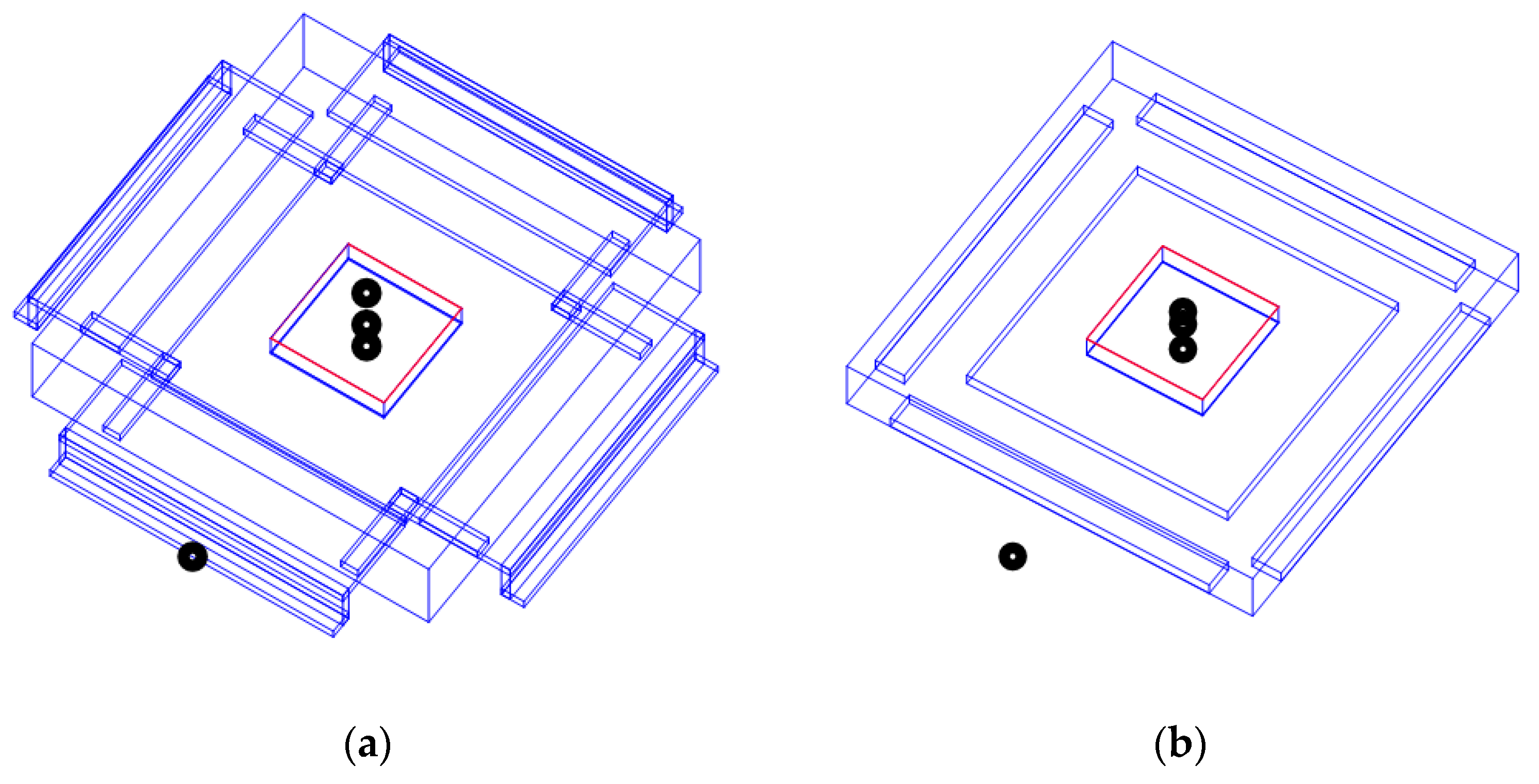
TRAC is suited to automatically compute the JEDEC metrics ϑJA, ΨJB, ΨJCtop, ϑJB, ϑJCtop, ϑJCbottom [2] in 4 ambients, which differ in terms of thermal path followed by the heat generated within the HS to emerge from the die; more specifically: the ambient to evaluate ϑJCbottom requires a cold plate in intimate contact with the package backside; for the computation of ϑJCtop the plate is located over the top surface; in the ambient for determining ϑJB, a cold ring surrounds the package; no cooling systems are exploited in the ambient common to ϑJA, ΨJB, ΨJCtop. In all ambients, the board over which the package is mounted is thermally modeled with a single finely-meshed parallelepiped with a thermal conductivity adjusted to account for the aggregate effect of metal traces and vias, the detailed representation of which would have unnecessarily made the thermal problem much more complex. As shown in Figure 1, the metrics are calculated from the temperatures probed in four positions, namely: (1) the point of the die where the peak (“junction”) temperature is reached; (2) the center of the top of the case; (3) the center of the bottom of the case; and (4) at the foot of the package lead half way along the side of the package (QFP) or within 1 mm of the package body (QFN). ϑJA is computed from (1) and the ambient temperature; ΨJB from (1) and (4); ΨJCtop from (1) and (2); ϑJB from (1) and (4); ϑJCtop from (1) and (2); ϑJCbottom from (1) and (3). As far as the metric ϑJCtop is concerned, a calibrated layer was interposed between the epad and the high-conductivity cold plate to emulate the epad-plate contact resistance. For all other metrics, the heat emerging from the die flows through the low-conductivity board, and the contact resistance epad-board was not accounted for, since it plays a negligible role.
As far as the BCs are concerned, specific values of heat transfer coefficients are applied to all surfaces of any structure (i.e., package and ambient) under test for each ambient; such values were preliminarily calibrated by comparing the JEDEC metrics simulated with commercial numerical programs with the experimental counterparts (see e.g., [2] for the measurement procedures) for a broad variety of package families.
For each parallelepiped, a mesh step size can be defined for each axis direction; as a result, a Cartesian mesh is automatically extracted. A finite integration technique (FIT) discretization [11] of the heat conduction problem is then generated in the form
where ϑ(p) is the N × 1 vector with the DoFs of the temperature rise distribution, K(p) is the N-order stiffness matrix, G(p) is a N × n power density matrix, p is the p × 1 parameter vector varying in a set , and P is the n × 1 vector containing the powers Pi (with i = 1,…, n) dissipated by the n independent HSs in the structure. These equations define the pDTM.
3. Parametric Compact Thermal Model
From the achieved pDTM, a pCTM can be extracted in a pre-processing stage. An N × q matrix U is determined, which allows approximating the N × 1 temperature rise vector in the form
for all p ϵ , in which is a q × 1 vector with q « N. The pCTM is derived from Equation (1) using Equation (2) and the Galerkin’s projection. In this way it results in
in which
are approximated by the technique described by some of the Authors in [9], which allows applying a fully generic transformation to the reference package; this improves the merely Cartesian transformation [4] adopted for the previous TRAC version presented in [10]. This system of equations, defining the pCTM, has formally the same structure of the system of equations defining the pDTM, but benefits from a significantly reduced complexity since q « N. Such a pCTM is updated at each iteration of the parametric MOR method, as in Algorithm 1. The iterations are stopped when, for novel values of the parameter vector p, the relative residual ξ does not exceed the assigned value Ξ, so that the pCTM does not vary any longer.
| Algorithm 1. Parametric model-order reduction (MOR) iteration. | |
| Step | |
| 1 | Pick up a value of p ϵ |
| if a pCTM has already been extracted then | |
| solve pCTM Equations (3) for | |
| determine ϑ(p) from Equation (2) using | |
| 2 | Determine the relative residual ξ of Equations (1) using ϑ(p) |
| ifξ > Ξ then | |
| 3 | Solve pDTM Equations (1) for ϑ(p) |
| 4 | Update U using ϑ(p) |
| 5 | Update the pCTM using U |
In Algorithm 1, at step 1, the elements of p ϵ are chosen equal to the values of the parameters defining the specimen in the family of packages for which the JEDEC thermal metrics must be computed. This strategy minimizes the time needed to evaluate the metrics for this case.
At step 2, the relative residual is determined as
V being the N-order diagonal matrix with the measures of the N volumes introduced in the FIT discretization.
At step 3, the solution of Equations (1) is ensured by a multigrid iterative solver, with a computational complexity linearly increasing with the dimension N of the problem.
At step 4, the U matrix is updated by appending a column orthonormal to the columns of the initial U matrix in the ‖•‖V norm, such that the columns of the final U matrix span ϑ(p).
At step 5, the updated U matrix is used for reconstructing the pCTM. Exploiting the fact that the last column of U is changed, the update of the pCTM does not require recomputing the whole model.
4. Numerical Results
The latest TRAC release allows describing and simulating the families of epad QFPs and QFNs, although the tool can be extended to other electronic components with relatively little effort. In particular, the package thickness [low-profile QFP (LQFP) and thin QFP (TQFP) types are considered, the thicknesses of which are 1.4 and 1 mm, respectively] and size, the number of leads, the epad size, the type of glue, the three dimensions of the die, as well as the HS size and position, are defined by twelve (QFP) or fourteen (QFN) parameters. The parameters can be easily selected through a user-friendly graphical interface, which also checks whether the whole parameter set corresponds to a package manufactured by the vendor. Some examples are as follows: the horizontal die dimensions can vary in a continue range between a minimum and a maximum value, the latter fixed by project rules to ensure the attachment between die and epad; the QFP die thickness can be chosen among 100, 280, 375 (value selected for the numerical results shown later), and 580 μm; the glue types used to attach die and pad, which differ in terms of thickness and thermal conductivity (the type with conductivity amounting to 6 W/mK was chosen).
Figure 1 shows the 3-D schematic representation of two specimens of the LQFP and QFN families.
The inherent symmetry of the packages under test allowed meshing and simulating only a quarter of each structure, thus reducing the computational burden; the missing portions were virtually restored by applying adiabatic BCs (i.e., zero heat flux) over the planes of symmetry.
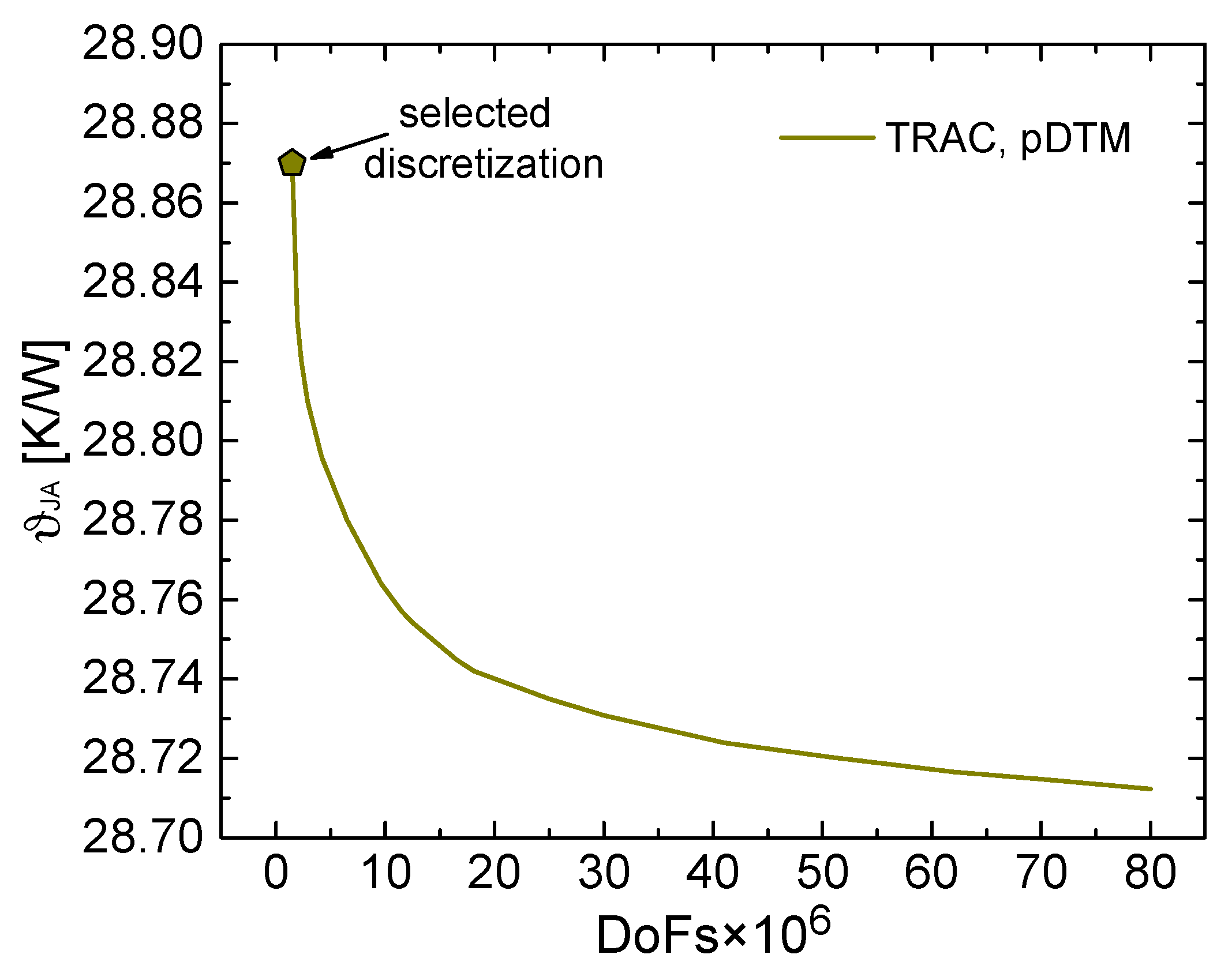
A preliminary convergence analysis of the spatial mesh discretization of the constructed pDTMs was performed for chosen packages; more specifically, the calculated thermal metrics were monitored by increasing the DoFs until a negligible mesh sensitivity was observed. Then the discretization leading to only <0.1% inaccuracy was selected not to face the computational effort required by extremely fine meshes, this choice being also justified by the higher uncertainty of the experimental data. Figure 2 illustrates the convergence analysis performed for an LQFP with a 10 × 10 mm2 package, a 4.5 × 4.5 mm2 epad, and a 2 × 2 mm2 die; as can be seen, the mesh leading to ϑJA = 28.87 K/W (1.487 × 10⁶ DoFs for a quarter of the structure) was chosen to avoid the huge number of DoFs (>50 × 106) required to obtain a negligibly more accurate ϑJA value.
The accuracy of the JEDEC thermal metrics computed by TRAC using the pDTM is witnessed by a comparison with a finite volume (FV) commercial software. This is shown in Figure 3, which reports the metrics ϑJA, ϑJB, and ϑJCtop (the others were not represented not to overcrowd the graphs) for a 10 × 10 mm2 LQFP and a 14 × 14 mm2 TQFP (Figure 3a), as well as for a 6 × 6 mm2 QFN (Figure 3b). The slight discrepancy between TRAC and the FV software must be attributed: (i) to the different mesh styles of the compared tools; and (ii) to the fineness degree adopted in both of them, which was not extremely high to prevent unnecessarily long CPU times. As can be seen, the thermal metrics decrease with increasing the die size (i.e., the HS size) due to the lower dissipated power density and the enhanced lateral heat spreading.
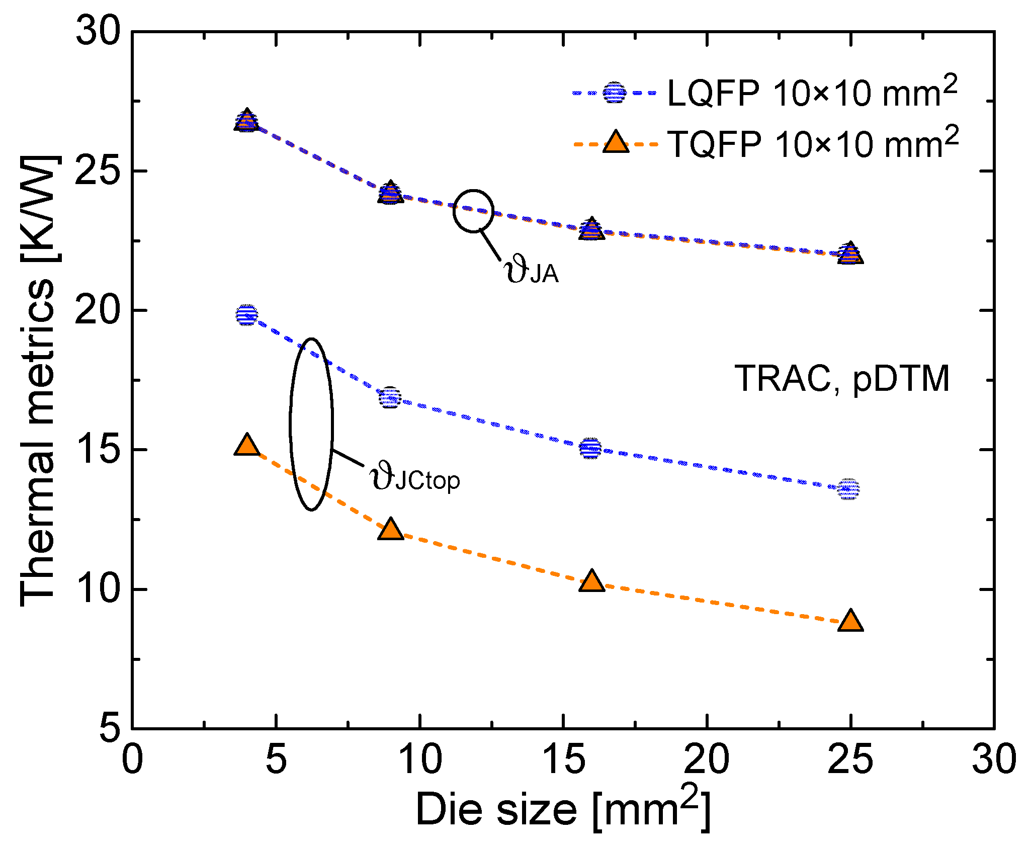
Figure 4 reports the metrics ϑJA and ϑJCtop as a function of die size for 10 × 10 mm2 LQFPs and TQFPs commonly sharing a 6 × 6 mm2 epad. It is inferred that the impact of the package thickness is significant only for ϑJCtop (for TQFPs, a 25–35% reduction of this metric is observed with respect to LQFPs), since in this case the heat generated in the die flows toward the cold plate placed on the top crossing the whole package; a marginal influence is instead found for all other metrics (including ϑJA), where the heat propagates mostly downward.
Lastly, using another available glue type with a reduced thermal conductivity (2 W/mK) for the die-epad attach was found to increase the downward-heat metrics by 15–25%, while ϑJCtop remains almost unaffected.
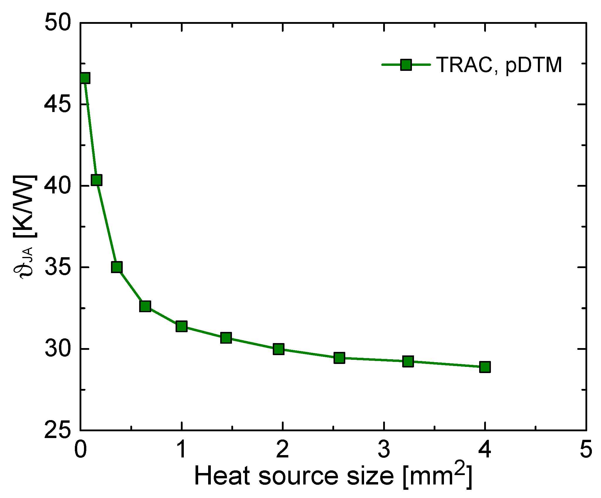
Differently from the previous tool version [10], where the power dissipation region was forced to coincide with the whole die, in the latest TRAC release it is also possible to select an HS with arbitrary size and position within the die, thus allowing the representation of more realistic conditions. Figure 5 shows the metric ϑJA as a function of HS size, the HS being centered in the die (which offers the possibility of meshing and simulating one quarter of the structure), for a 10 × 10 mm2 LQFP with a 4.5 × 4.5 mm2 epad and a 2 × 2 mm2 die; the assigned dissipated power amounts to 1 W regardless of the HS size. As expected, ϑJA markedly increases with reducing the HS size, which implies a growth in power density. This analysis allows concluding that a correct representation of the HS geometry (which depends on the specific application) is of utmost importance for an accurate evaluation of the thermal metrics of electronic packages.
Lastly, a pCTM of any of the derived pDTMs, ensuring accuracy better than 0.5% in the reconstruction of the thermal field, was extracted in less than 20 min on an iMac with a 3.5 GHz Intel Core i7 according to Algorithm 1; the resulting pCTMs enjoy less than 70 DoFs (to be compared with a few millions for the pDTMs). It is worth noting that the steady-state thermal simulation corresponding to a given set of parameters requires 10–20 s for the pDTM (depending on the package), 30–60 s for the FV commercial software, and less than 0.2 s using the pCTM in TRAC. A comparison of the results from the pDTM and the pCTM is shown in Figure 6 for various QFPs.
5. Conclusions
In this paper, a tool denoted as TRAC has been presented. TRAC determines the steady-state thermal behavior of electronic packages with Manhattan geometry, the key geometrical and material parameters of which vary in an assigned range. The latest TRAC release allows the straightforward definition of pDTMs, as well as the automatic and fast (about 20 min) extraction of pCTMs in a pre-processing stage, for two families of packages. In addition, it automatically provides the JEDEC thermal metrics corresponding to selected packages, thereby favoring an easy evaluation of the influence of the key parameters (e.g., die size, package thickness, die-epad attach material). Compared to a FV commercial software, a simulation performed by TRAC using a pDTM takes about ⅓ of the CPU time, while the adoption of a pCTM leads to almost instantaneous results without any loss of accuracy. Moreover, TRAC is equipped with a user-friendly graphical interface that simplifies the choice of parameters and thus the construction of the geometry and mesh of the corresponding package. Owing to its features, TRAC can be used by semiconductor vendors with a two-fold aim: (1) to let customers effortlessly evaluate the thermal metrics of the packages they want to purchase through, for example, a web application; and (2) to support the design of more complex electronic systems.
TRAC variants suited to simulate other package families, handle multiple heat sources, and carry out dynamic thermal analyses are currently under development.
Author Contributions
Methodology, L.C.; Software, L.C. and S.R.; Validation, D.G., A.M., and C.M.V.; Investigation, L.C., S.R., and V.d.; Writing—Original Draft Preparation, V.d. and S.R.; Writing—Review & Editing, V.d. and S.R.; Supervision, C.M.V.
Funding
This research received no external funding.
Conflicts of Interest
The authors declare no conflict of interest.
Nomenclature
| ϑJA (K/W) | junction to ambient thermal resistance |
| ΨJB (K/W) | thermal characterization parameter to report the difference between junction temperature and the temperature of the board measured at the top surface of the board |
| ΨJCtop (K/W) | thermal characterization parameter to report the difference between junction temperature and the temperature at the top center of the outside surface of the component package |
| ϑJB (K/W) | junction to board thermal resistance |
| ϑJCtop (K/W) | junction to case top thermal resistance |
| ϑJCbottom (K/W) | junction to case bottom thermal resistance |
| TRAC | thermal resistance advanced calculator |
| BC | boundary condition |
| BCI | BC independent |
| CTM | compact thermal model |
| pCTM | parametric CTM |
| DTM | detailed thermal model |
| pDTM | parametric DTM |
| DoF | degree of freedom |
| epad | exposed pad |
| FIT | finite integration technique |
| FV | finite volume |
| HS | heat source |
| JEDEC | joint electron device engineering council |
| QFP | quad flat package |
| LQFP | low-profile (thick) QFP |
| TQFP | thin QFP |
| QFN | quad flat no-leads package |
| MOR | model-order reduction |
References
- Lasance, C. Ten years of boundary-condition-independent compact thermal modeling of electronic parts: A review. Heat Transfer Eng. 2008, 29, 149–169. [Google Scholar] [CrossRef]
- JESD51-12. Guidelines for Reporting and Using Electronic Package Thermal Information; JEDEC: Arlington, VA, USA, 2005. [Google Scholar]
- Codecasa, L.; d’Alessandro, V.; Magnani, A.; Rinaldi, N.; Zampardi, P.J. FAst Novel Thermal Analysis Simulation Tool for Integrated Circuits (FANTASTIC). In Proceedings of the International Workshop on THERMal INvestigation of ICs and systems (THERMINIC), London, UK, 24–26 September 2014. [Google Scholar]
- Codecasa, L.; d’Alessandro, V.; Magnani, A.; Rinaldi, N. Parametric compact thermal models by moment matching for variable geometry. In Proceedings of the International Workshop on THERMal INvestigation of ICs and systems (THERMINIC), London, UK, 24–26 September 2014. [Google Scholar]
- Janssen, J.H.J.; Codecasa, L. Why matrix reduction is better than objective function based optimization in compact thermal model creation. In Proceedings of the International Workshop on THERMal Investigation of ICs and systems (THERMINIC), Paris, France, 30 September–2 October 2015. [Google Scholar]
- Codecasa, L.; d’Alessandro, V.; Magnani, A.; Rinaldi, N. Matrix reduction tool for creating boundary condition independent dynamic compact thermal models. In Proceedings of the International Workshop on THERMal INvestigation of ICs and systems (THERMINIC), Paris, France, 30 September–2 October 2015. [Google Scholar]
- Codecasa, L.; d’Alessandro, V.; Magnani, A.; Rinaldi, N. Structure preserving approach to parametric dynamic compact thermal models of nonlinear heat conduction. In Proceedings of the International Workshop on THERMal INvestigation of ICs and systems (THERMINIC), Paris, France, 30 September–2 October 2015. [Google Scholar]
- Rogié, B.; Codecasa, L.; Monier-Vinard, E.; Bissuel, V.; Laraqi, N.; Daniel, O.; D’Amore, D.; Magnani, A.; d’Alessandro, V.; Rinaldi, N. Delphi-like dynamical compact thermal models using model order reduction. In Proceedings of the International Workshop on THERMal INvestigation of ICs and systems (THERMINIC), Amsterdam, The Netherlands, 27–29 September 2017. (best paper award). [Google Scholar]
- Codecasa, L.; d’Alessandro, V.; Magnani, A.; Rinaldi, N. Novel approach for the extraction of nonlinear compact thermal models. In Proceedings of the International Workshop on THERMal INvestigation of ICs and systems (THERMINIC), Amsterdam, The Netherlands, 27–29 September 2017. [Google Scholar]
- Codecasa, L.; Race, S.; d’Alessandro, V.; Gualandris, D.; Morelli, A.; Villa, C.M. Thermal Resistance Advanced Calculator (TRAC). In Proceedings of the International Workshop on THERMal INvestigation of ICs and Systems (THERMINIC), Stockholm, Sweden, 26–28 September 2018. [Google Scholar]
- Codecasa, L.; Specogna, R.; Trevisan, F. Base functions and discrete constitutive relations for staggered polyhedral grids. Comput. Meth. Appl. Mech. Eng. 2009, 198, 1117–1123. [Google Scholar] [CrossRef]
Figure 1.
Specimens of the LQFP (a) and QFN (b) families sharing the same size of package (6 × 6 mm2), epad (4.5 × 4.5 mm2), and die (2 × 2 mm2). Black circles represent the temperature probes needed to determine the thermal metrics.
Figure 1.
Specimens of the LQFP (a) and QFN (b) families sharing the same size of package (6 × 6 mm2), epad (4.5 × 4.5 mm2), and die (2 × 2 mm2). Black circles represent the temperature probes needed to determine the thermal metrics.

Figure 2.
JEDEC thermal metric ϑJA as a function of the number of DoFs, as evaluated through the pDTM for a quarter of the 10 × 10 mm2 LQFP with a 4.5 × 4.5 mm2 pad and a 2 × 2 mm2 die. The selected discretization is indicated.
Figure 2.
JEDEC thermal metric ϑJA as a function of the number of DoFs, as evaluated through the pDTM for a quarter of the 10 × 10 mm2 LQFP with a 4.5 × 4.5 mm2 pad and a 2 × 2 mm2 die. The selected discretization is indicated.

Figure 3.
Some JEDEC thermal metrics against die size, as determined from the pDTM (blue) and a FV commercial software (red): (a) 10 × 10 mm2 LQFP (circles) and 14 × 14 mm2 TQFP (triangles), both with a 6 × 6 mm2 epad; (b) 6 × 6 mm2 QFN (squares) with a 4.7 × 4.7 mm2 epad.
Figure 3.
Some JEDEC thermal metrics against die size, as determined from the pDTM (blue) and a FV commercial software (red): (a) 10 × 10 mm2 LQFP (circles) and 14 × 14 mm2 TQFP (triangles), both with a 6 × 6 mm2 epad; (b) 6 × 6 mm2 QFN (squares) with a 4.7 × 4.7 mm2 epad.

Figure 4.
JEDEC thermal metrics ϑJA and ϑJCtop vs. die size evaluated with the pDTM; results obtained for 10 × 10 mm2 LQFPs (blue circles) are compared with the TQFP counterparts (orange triangles); in both cases, a 6 × 6 mm2 epad is considered.
Figure 4.
JEDEC thermal metrics ϑJA and ϑJCtop vs. die size evaluated with the pDTM; results obtained for 10 × 10 mm2 LQFPs (blue circles) are compared with the TQFP counterparts (orange triangles); in both cases, a 6 × 6 mm2 epad is considered.

Figure 5.
JEDEC thermal metric ϑJA vs. HS size for a square HS centered in the die, as evaluated through the pDTM for a 10 × 10 mm2 LQFP with a 4.5 × 4.5 mm2 epad and a 2 × 2 mm2 die.
Figure 5.
JEDEC thermal metric ϑJA vs. HS size for a square HS centered in the die, as evaluated through the pDTM for a 10 × 10 mm2 LQFP with a 4.5 × 4.5 mm2 epad and a 2 × 2 mm2 die.

Figure 6.
Comparison of the JEDEC thermal metric ϑJA provided by both a pDTM and a pCTM for various QFPs.
Figure 6.
Comparison of the JEDEC thermal metric ϑJA provided by both a pDTM and a pCTM for various QFPs.

© 2019 by the authors. Licensee MDPI, Basel, Switzerland. This article is an open access article distributed under the terms and conditions of the Creative Commons Attribution (CC BY) license (http://creativecommons.org/licenses/by/4.0/).
Share and Cite
MDPI and ACS Style
Codecasa, L.; Race, S.; d’Alessandro, V.; Gualandris, D.; Morelli, A.; Villa, C.M. TRAC: A Thermal Resistance Advanced Calculator for Electronic Packages. Energies 2019, 12, 1050. https://doi.org/10.3390/en12061050
AMA Style
Codecasa L, Race S, d’Alessandro V, Gualandris D, Morelli A, Villa CM. TRAC: A Thermal Resistance Advanced Calculator for Electronic Packages. Energies. 2019; 12(6):1050. https://doi.org/10.3390/en12061050
Chicago/Turabian StyleCodecasa, Lorenzo, Salvatore Race, Vincenzo d’Alessandro, Donata Gualandris, Arianna Morelli, and Claudio Maria Villa. 2019. "TRAC: A Thermal Resistance Advanced Calculator for Electronic Packages" Energies 12, no. 6: 1050. https://doi.org/10.3390/en12061050
Note that from the first issue of 2016, this journal uses article numbers instead of page numbers. See further details here.