Article

A Harmonic Based Pilot Protection Scheme for VSC-MTDC Grids with PWM Converters

Department of Energy Technology, Aalborg University, 9220 Aalborg, Denmark
*
Author to whom correspondence should be addressed.
Energies 2019, 12(6), 1010; https://doi.org/10.3390/en12061010
Submission received: 20 January 2019 / Revised: 10 March 2019 / Accepted: 11 March 2019 / Published: 15 March 2019

Abstract

:
This paper presents a selective harmonic-based pilot protection scheme for detecting faults happened in the DC transmission section of VSC-MTDC grids with pulse width modulation (PWM) voltage source converters (VSCs). When a DC fault occurs in VSC-MTDC grids with PWM converters, first carrier frequency harmonic (FCFH) currents will be generated by all VSCs through the grid. FCFH currents have different flowing directions depending on the characteristics and the location of the fault. According to the characteristics of the existing FCFH in the fault currents, a selective pilot protection algorithm is designed for VSC-MTDC grids. Considering the internal and external DC transmission faults for specific zones, and the circulating flow of FCFH current in the DC link capacitors, the relays cannot detect FCFH currents for external faults, while for the internal faults, FCFH currents are clearly detected. To design the selective protection algorithm, Hilbert-Huang transform (HHT) is used to detect the instantaneous frequency and the instantaneous amplitude of the high frequency intrinsic mode function (IMF)s, which are extracted from the fault current waves. Multiple faults with different characteristics are applied to CIGRE DCS-2 VSC-MTDC grid with two-level and three-level VSCs modeled in PSCAD, and the HHT-based selective protection scheme is designed in MATLAB. According to the results, the proposed algorithm can truly discriminate between internal and external faults.

1. Introduction

High voltage direct current transmission (HVDC) systems play a major role in bulk electrical power transmission. HVDC links with voltage source converters (VSC-HVDC) have remarkable advantages over traditional line commutated HVDC (LCC-HVDC) links and they are getting increasing attention to be considered as the main technology for future HVDC installations [1]. The important advantages of VSC-HVDC systems are the bidirectional flowing of power and enabling multi-terminal VSC-HVDC (VSC-MTDC) grids [2], which are more flexible for power transmission between multiple AC regions [3]. However, technical challenges exist in the protection and control of VSC-MTDC networks [4]. Fast fault isolation is only possible using DC breaker (DCCB)s [5] or converters with fault blocking capability [6]. Additionally, selective and fast detection of faults is difficult for the protection algorithm, because it must be done in less than 5 milliseconds in order to have minimum damage in HVDC converter switches [7] and correctly detect the faulty section of the transmission grid. According to the mentioned challenges in the protection of VSC-MTDC grids, designing fast, accurate and selective fault detection algorithms is one of the important topics in the field of HVDC protection and is investigated in this study.
The majority of the latest literature studies in designing protection algorithms for VSC-MTDC grids are based on fault voltage or current traveling wave (TW)s [8,9,10], harmonics-based algorithms [11,12], voltage or current transients [13], the rate of change of voltage (ROCOV) and current (ROCOC) [14] and artificial intelligence (AI) based methods [15]. TW-based techniques give accurate fault detection results as the most feasible methods [16]. However, TW-based methods need high sampling and they are highly dependent on the initial peak of the fault waves. The advantage of transient-based techniques is having good selectivity in determining the faulty section. However, they are sensitive to noise, which exists in practical environment. The authors in [12] presented an overcurrent method to detect a certain range of frequencies in the fault current waves using the short-time Fourier transform (STFT). The proposed method gives reasonable fault detection results, but the selectivity of the proposed method is not verified for faults close to one of the measurement locations in the VSC-MTDC grid. As a matter of fact, overcurrent based methods simply targeting a certain range of frequencies may not have the required selectivity. Additionally, the parameter adjustment of the protection algorithm to cover all types of faults in the different locations of the grid is challenging. Other harmonic-based techniques, extract the existing harmonics in fault voltage and current waves in order to design protection algorithms, using different signal processing techniques like Wavelet transform (WT) [17,18]. The authors in [19] proposed a harmonic-based protection technique for LCC-HVDC links. Various fault events applied to the system, and 12th, 24th, and 36th harmonics of the voltage of 12-pule converter used to design the fault detection algorithm. However, the defined method for LCC-HVDC is not applicable to VSC-HVDC grids. In another harmonic-based protection study, the authors used first carrier frequency harmonic (FCFH) current for designing fault detection algorithms for VSC-HVDC transmission systems [20]. The FCFH current of PWM converters has useful information for detecting faults in VSC-HVDC grids. However, the paper only studied the discrimination between external AC faults and internal DC faults in point to point (P2P) VSC-HVDC grids, which can not be used as a fault detection study for VSC-MTDC grids [20].
Hilbert-Huang Transform (HHT), is a time-frequency signal processing method that can be used for electrical power system protection [21]. In HHT, firstly fault TWs are decomposed by the empirical mode decomposition (EMD) method, and the inherent mode functions (IMF) are extracted from the waves. In the second stage, the Hilbert transform (HT) is applied to the resulted EMDs to determine the instantaneous amplitude (IA), and instantaneous frequency (IF) of the IMF components [22]. With the help of IF, the arrival time of the initial peaks can be accurately detected. HHT has been used in different topics in electrical power systems [23]. HHT has advantages over Fourier transform (FT), and Wavelet transform (WT), as follows:
  • WT and FT do not describe the frequency changing with time, while HHT gives the instant frequency of the transient waves with the most accurate results. FT gives signal information only in frequency resolution, and WT gives a time-frequency resolution with a trade-off between the accuracy in time or frequency. However, HHT gives signal information in time-instant frequency resolution in an accurate form.
  • In HHT the processed data are only dependent on the inherent characteristics of the signal, with no adjustments of the algorithm parameters, which result in more accurate and faster signal processing results. However, in WT, the signal is sifted according to the type of mother wavelet and the decomposition level, causing noticeable differences to the accuracy of the results.
This paper proposes a fault detection algorithm for VSC-MTDC grids, based on FCFH current, which exists due to the inherent characteristic of PWM converters [24]. FCFH currents are extracted by HHT from converter DC links with different circulating directions when there are faults in different zones of the system. The results show that the proposed fault detection technique is able to selectively detect the fault with different resistance and in various locations. A VSC-MTDC grid is modeled in PSCAD/EMTDC based on two-level, and three-level PWM voltage source converter (VSC)s and FCFH current is extracted in MATLAB using HHT. The structure of three-level VSCs brings high voltages with low harmonics without the use of transformer [25]. Accordingly, the contributions of this paper are as follows:
  • This paper analyses the flow of FCFH current in VSC-MTDC grids in different situations. For different regions of the system, the behavior of the FCFH fault current in external and internal faults is compared and a methodology for selective fault detection ins VSC-MTDC grids is proposed.
  • This paper uses HHT to accurately detect the initial peaks of the FCFH currents with the help if the instant frequency. The detection delay is significantly lower than WT and FT-based methods. Additionally, WT and FT-based frequency analysis deal with constant frequency detection in different levels, while HHT can determine abrupt time-varying changes in dominant frequency within a certain EMD.
  • Different PWM converter topologies, namely, two-level and three-level VSCs are used in the simulated models to analyses different VSC-MTDC grid topologies and have a more generalized method, applicable to a wider range of systems.
  • Multiple faults with different characteristics and types, which involve one or both of the poles including high resistance faults are applied to the system to test the robustness of the method.
  • The proposed fault detection algorithm is selective and can accurately detect the faults in different locations of the VSC-MTDC grid regardless of the power flow of the system and the type of inner and outer control system in the HVDC grid.
  • Unlike the TW-based methods, the proposed technique does not require to detect the second reflections. The noise sensitivity of the proposed algorithm is less than the transient-based methods, and the selectivity of the proposed technique is significantly higher than over current/over voltage-based methods. The mathematical calculations of the proposed scheme are simpler than AI-based techniques and are practically more feasible.
The remainder of this paper is written as follows: Section 2, explains the principle FCFH current analysis for internal and external faults in VSC-MTDC networks. Section 3 explains the proposed HHT-based protection algorithm. Section 4 gives the test system details and data with defined internal and external faults. The simulation results are depicted in Section 5, discussion about the results are proposed in Section 6 and the conclusions are given in Section 7.

2. Analysis of FCFH Current in VSC-MTDC Grids

The general form of harmonics generated in PWM modulations can be explained in the following form [26,27]:
f ( t ) = A 00 2 + n = 1 [ A 0 n cos ( n ( ω 0 t + θ 0 ) ) + B 0 n sin ( n ( ω 0 t + θ 0 ) ) ] + m = 1 [ A m 0 cos ( m ( ω c t + θ c ) ) + B m 0 sin ( m ( ω c t + θ c ) ) ] + m = n = n 0 [ A m n cos ( m ( ω c t + θ c ) ) + n ( ω 0 t + θ 0 ) + B m n sin ( m ( ω c t + θ c ) ) + n ( ω 0 t + θ 0 ) ]
Equation (1) consists of four main parts:
  • The first part is the PWM DC offset, claiming m = n = 0 .
  • The baseband harmonics, which consists of the fundamental frequency component and also the low order frequency component ( m = 0 ).
  • Carrier wave harmonics, which is the high-frequency component ( n = 0 ).
  • The sideband harmonics around the carrier harmonic components, which is of interest in designing the proposed protection algorithm.
Normally, the baseband harmonics (the second and the third part) have very small neglectable amplitude. Considering the first carrier frequency harmonic defined as the value of unity for the carrier index ( m = 1 ), the second and the fourth harmonics around FCFH ( ω c ± 2 ω 0 and ω c ± 4 ω 0 ) are the dominant harmonics [25]. This general form of harmonics exists in the fault current, which flows into the transmission section and circulates into the converter DC link capacitors. This existing harmonics in the fault current is used to selectively detect the faulty transmission section in VSC-MTDC grids. Figure 1 shows the single line diagram of a radial VSC-MTDC transmission link. The converter DC link capacitors filter DC harmonics currents. Considering PWM switching for converters with the mentioned dominant harmonics, the parameters ω c and ω 0 are the first carrier wave frequency, and the reference frequency, respectively [28]. With the FCFH generation of PWM converters during fault conditions, and by usig the difference in the characteristics of FCFH current in different fault conditions, a criterion for designing selective fault detection algorithm for VSC-MTDC grids can be defined [20].
Generally, two-level VSCs generate more harmonics and inter-harmonics than three level and multi-level converters, especially on high order harmonics. Although filtering installations exist on the AC side, a part of the harmonics and inter-harmonics flow into the HVDC transmission section, including FCFH harmonics in case of faults in either of DC and AC sides [29,30].
The flowing of FCFH current for external and internal faults is analyzed in the following section:

2.1. External Faults

When pole-to-pole (P2P) fault F 1 occurs in the zone 3 of the system depicted in Figure 1 as an external fault for the protective relays installed in zone 2, the fault current flow is depicted as the red arrows. During the fault condition, all converters generate FCFH currents. The fault harmonic currents I F R 1 , I F R 2 , I F R 3 , and I F R 4 , will flow through the DC link capacitors in a circular form. Considering the zone 2 positions of relays R P 3 and R P 4 installed after the DC link capacitors, the detection of FCFH current passing through DC link capacitors, namely I F C 3 and I F C 4 is not possible for the mentioned relays. Accordingly, the relays of zone 2 cannot detect external faults occurring in zones 1 and 3.

2.2. Internal Faults

When the DC P2P fault F 2 occurs inside zone 2, the current flows are depicted in Figure 2. Similar to the previous case, all converters generate FCFH currents. According to the circulating flow of I F C 2 and I F C 3 in zone 2, they will be detected by both protective relays R P 3 and R P 4 . However, the amplitude of fault harmonic currents depends on the location and the resistant of the fault.
The interesting scenarios of flowing of FCFH current are depicted based on time-instant frequency analysis later in Section 5. Some of the relay detection figures which are similar to the given figures, or the relay detection figures which are not of interest are skipped. The skipped figures mainly consist of the external relays, where I F C and I F R both rotate in DC link capacitor loop behind the relays.
This property of FCFH fault current in different fault situations can be extended to different locations of the transmission grid and can be used as a criterion for designing a selective fault detection technique for VSC-MTDC grids. The proposed method does not depend on the power flow of the system and it is valid for different fault types in the DC section, namely pole to pole (P2P), positive pole to the ground (PP2G) and negative pole to the ground (NP2G). However, a robust signal-processing technique is needed to detect the FCFH current characteristics accurately. It is handled by the Hilbert-Huang transform (HHT), which is explained in Section 3.

3. The Hilbert-Huang Transform

Hilbert-Huang Transform (HHT), is a time-instant frequency signal-processing technique, which can be used for fault detection and localization in HVDC links. Using HHT, fault TWs will be decomposed by the empirical mode decomposition (EMD), and the inherent mode functions (IMF) will be extracted. Then, using the Hilbert transform, the instantaneous amplitude of the proper IMF component is calculated. Accordingly, HHT consists of two steps: EMD decomposition, and the Hilbert transform.

3.1. Empirical Mode Decomposition (EMD)

Empirical mode decomposition (EMD), introduced by Huang [31] is a sifting process, which decomposes the signal into several modes, similar to wavelet transform. Each IMF must satisfy two conditions:
(1) In the whole data window, the number of extremum points and zero-crossings points must be equal or different by one value.
(2) At any point, the mean value of the envelope defined by local maxima and the envelope defined by the local minima is zero.
The EMD decomposition for any signal s ( t ) is comprehensively explained in [32]. It is also included in the flowchart of the main algorithm in Figure 3. In summary, the original signal s ( t ) can be expressed as follows:
s ( t ) = i = 1 n c i ( t ) + r n ( t )
where, c i ( t ) and r n ( t ) are the ith IMF component and the residue, respectively.

3.2. The Hilbert Transform

After decomposing the input signal into a series of IMFs, the instantaneous frequency of each IMF can be determined using the Hilbert transform. The corresponding Hilbert transform for IMF c i ( t ) is:
y i ( t ) = H [ c i ( t ) ] = c i ( τ ) π ( t τ ) d τ
the summation of the input IMF and the transformed output, gives z ( t ) as:
z i ( t ) = c i ( t ) + j y i ( t ) = A i ( t ) e j θ i ( t )
where:
A i ( t ) = c i 2 ( t ) + y i 2 ( t ) , θ i ( t ) = tan 1 y i ( t ) c i ( t )
in the aforementioned equations, A i ( t ) and θ i ( t ) are instantaneous amplitude and phase for IMF c i . The instantaneous frequency for IMF c i can be determined using:
f i ( t ) = 1 2 π d θ i ( t ) d t
The IMFs of fault current wave are extracted through EMD. Then, the corresponding instantaneous frequency and amplitude of IMF1 as the highest frequency component will be calculated using HHT.

3.3. Physical Interpretation of HHT

The main goal of using HHT is to have a different view of the time, frequency and energy properties of the signals. Using the signal-processing approach proposed by HHT, the non-stationarity of the fault current waves can be analyzed in a more accurate way than the constant amplitude and frequency principles used by FT and WT [33]. In the first step, the IMFs are extracted from the fault current waves using EMD method, which can decompose any array of data to a limited number of IMFs. The main reason of using EMD method as the first stage of HHT is that the principle of instant frequency, which means the detection of instant local phase changes, works best with the IMF resulted from EMD method than any other time-based arrays of data. According to the two conditional sentences for detecting IMFs through EMD, unlike the static amplitude and frequency of harmonic component detected by WT and FT, an IMF can have dynamic amplitude and frequency changing over time. To detect to IMFs using EMD, the local maxima and minima are detected in the data array. Then all detected local maxima and local minima are separately connected via cubic spline line, as the upper and the lower envelopes. Then the average of the signal is calculated and subtracted from the signal.
In the second stage, the instant frequency is calculated for the IMFs. The physical interpretation of the instant frequency is the rate of change of the instantaneous phase of the complex IMFs. In fact, IF is the rate of change of the cycle compared to the time axis.

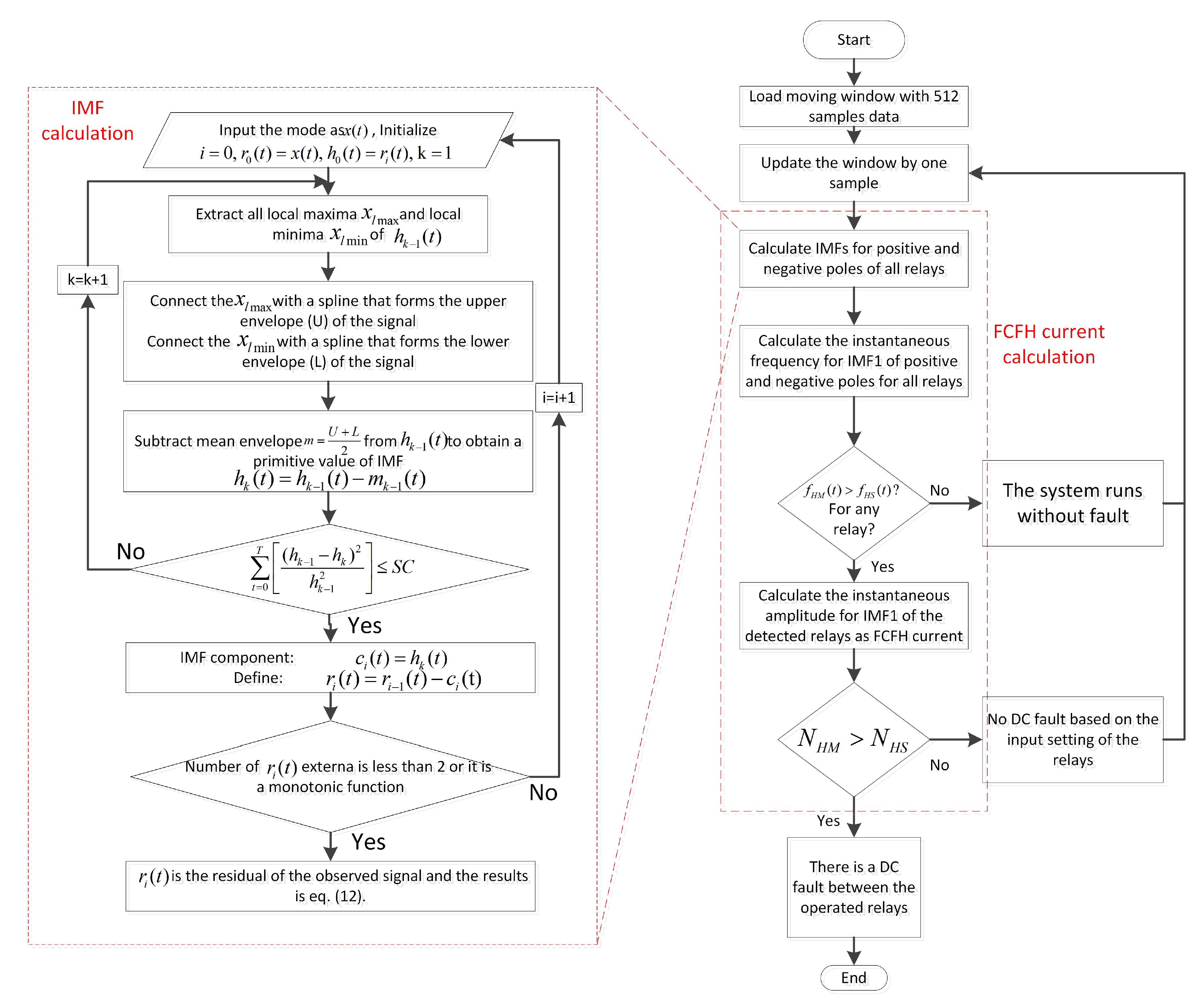
3.4. The Proposed Harmonic Based Protection Algorithm

The complete flowchart of the proposed pilot protection scheme is given in Figure 3. The algorithm starts with defining a moving window with 512 samples for all positive and negative pole relays installed on all sections. As the first step of HHT, the IMFs are calculated for the moving window and then the instant frequency is calculated. The instant frequency is used to detect any initial peaks regarding faults or transient disturbances. If the measured instant frequency ( f H M ( t ) ) is bigger than the threshold setting instant frequency ( f H S ( t ) ), the FCFH harmonic count is investigated using the instant amplitude. If the measured FCFH harmonic count in the instant amplitude ( N H M ) is bigger then the defined threshold setting for the FCFH harmonic count ( N H S ), then the candidate relays are detected for triggering and the transmission section between them is chosen as the faulty section. A sub-level for calculating IMFs is also included in the flowchart.

4. The Test System and the Case Studies

In this study, a multi-terminal VSC-HVDC grid proposed in [34] is modeled in PSCAD/EMTDC, and further HHT-based signal processing scripts are written in MATLAB. The modeled VSC-MTDC system has a symmetric monopole topology with two different main cases with modified two-level and three-level PWM VSCs. The transmission sections are extruded HVDC cables with the radial dimensions shown in Figure 4. Table 1 shows the parameters of the test system. There is a total of 12 relays in the system, each of them watching one side of a transmission cable. Four fault cases are applied as the main case studies. Several faults are also considered as sensitivity analysis for the proposed protection scheme. The fault parameters are given in Table 2. Faults I and II are considered as external and internal faults for relays of zone 2 for the system two-level VSCs and faults III and IV are high impedance external and internal faults for relays of zone 2 for the system with three-level VSCs.

5. Simulation Results

In this section the defined faults are applied to the model and the resulted waves are depicted. The test parameters are given in Table 3:

5.1. Case 1: Two-Level VSCs

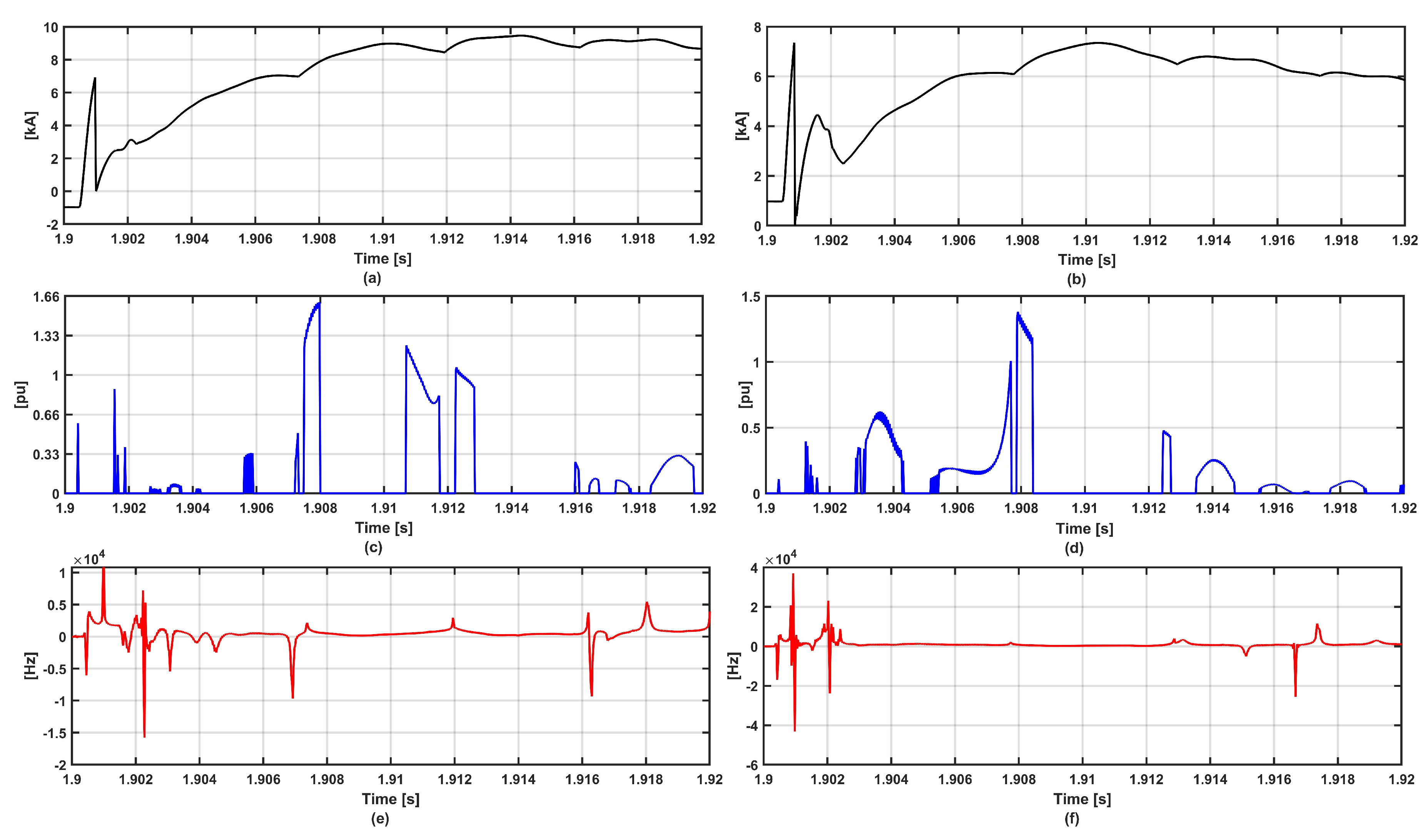
In this case, Fault I and II are applied to the model with two-level PWM VSCs. Figure 5 and Figure 6 depict the fault current waves for the positive pole and the corresponding HHT-based results for faults I and II, respectively. Table 4 shows the fault detection results for case 1. According to Table 4 none of the relays in zone 2 detected fault I, while all of them detected fault II as an internal fault for zone 2.

5.2. Case 2: Three-Level VSCs

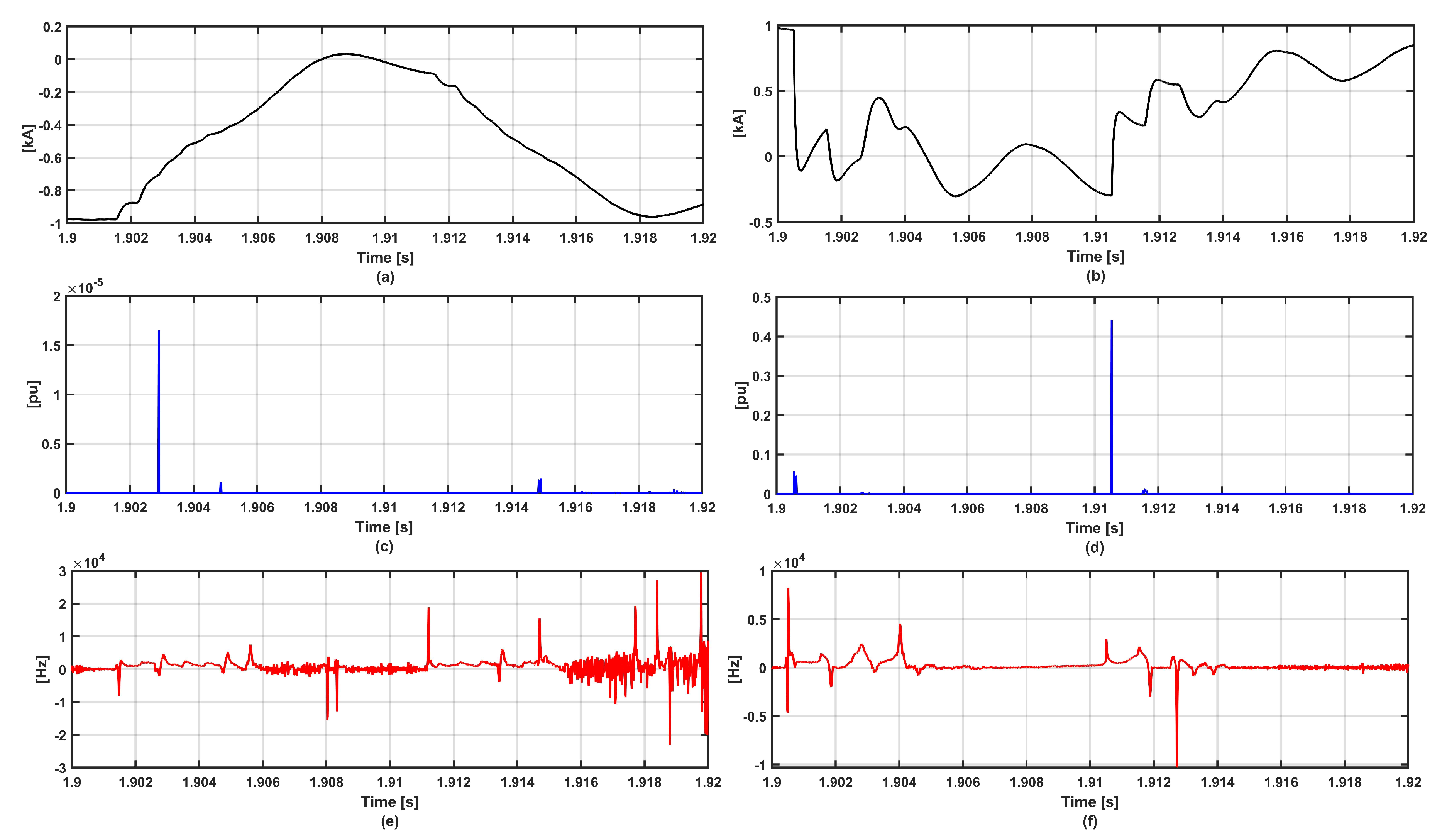
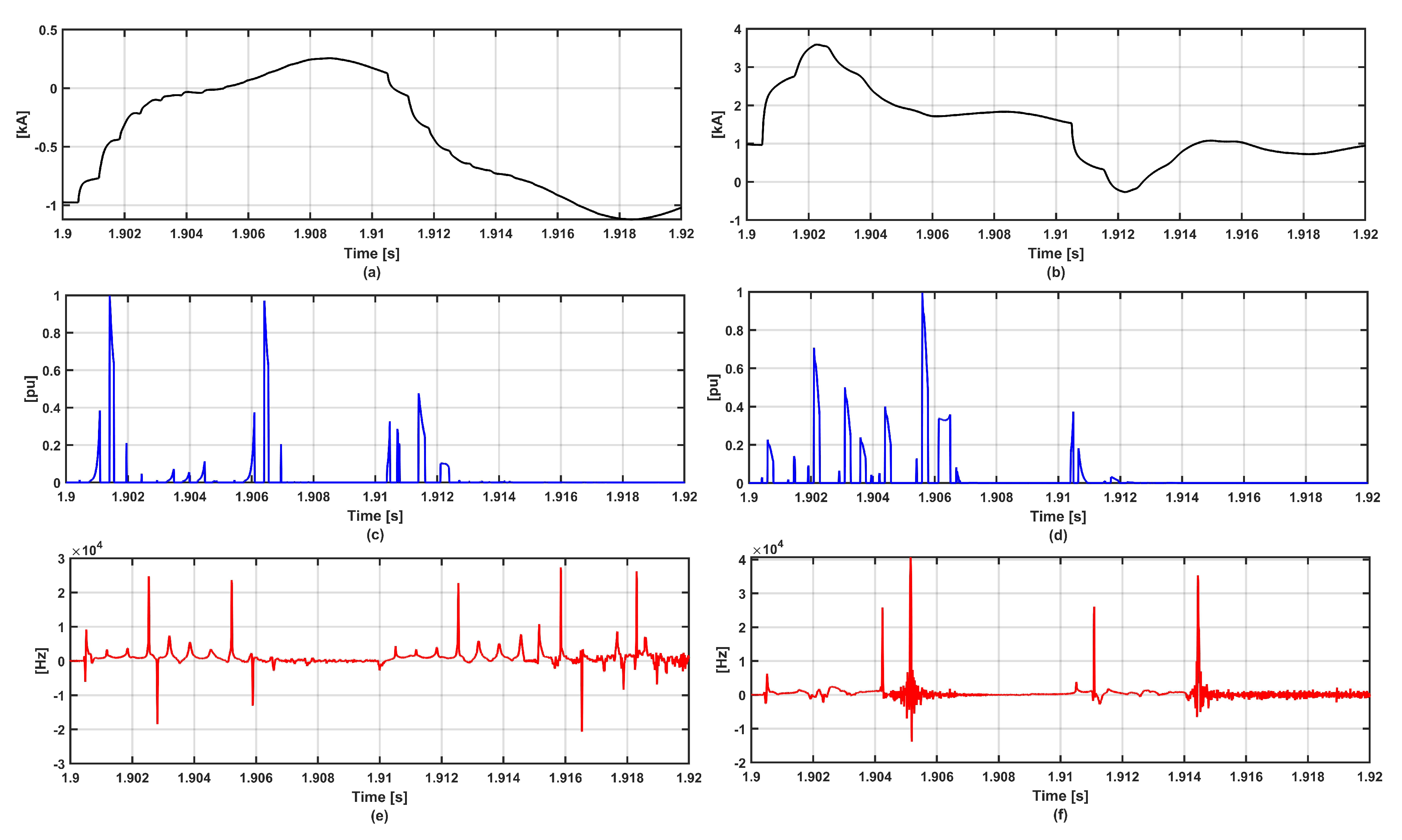
In the second case, Fault III and IV are applied to the model with three-level PWM VSCs. Figure 7 and Figure 8 depict the fault current waves for the positive pole and the corresponding HHT-based results for faults III and IV, respectively. Table 5 gives the fault detection results for this case. According to Table 5, none of the zone 2 relays, detected fault III as the internal fault for zone 2. The positive pole relays in zones 2 ( R P 3 and R P 4 ) detected fault IV as an internal fault for zone 2, while zone 2 negative pole relays did not detect the fault. Accordingly, the fault is a positive pole to the ground fault for zone 2.

5.3. Sensitivity Analysis for Internal Faults

In this section, the impact of fault location and fault resistance is analyzed with more fault scenarios. Fault I is applied to zone 2 with different locations and impedances for in-depth analysis of the accuracy of the proposed protection scheme. Table 6 gives the fault parameters and the detection sample delays by HHT algorithm. All faults are detected successfully by HHT and the low sample delay in detecting the faults proves the accuracy of the protection scheme.

6. Discussion

According to the results given in Section 5, HHT detects the faults with a reasonable amount of sample delay. In fault I, the relays on zone 2 did not trigger, while all of them detected fault II as an internal fault for zone 2. The instant amplitude was higher than the threshold settings for fault II with the I H M values of 1.057, 1.1898, 0.8697 and 0.9659 p.u. for relays R P 3 , R P 4 , R N 3 , and R N 4 , respectively. The sample delays for this case are 1 and 2 samples. Accordingly, the proposed results are reasonably fast for this case.
Regarding the fault III, zone 2 relays did not trigger again due to being an external fault for zone 2. According to the results given in Table 5, when fault IV which is a PP2G fault, happens to the system, the relays R P 3 and R P 4 detect the fault with I H M values of 0.9405 and 0.9547 p.u., respectively. The N H M count is also higher than the threshold setting, which is set according to ref [20]. The sample delay is 3 for both relays, which are reasonable according to the high impedance of the fault (100 Ω ). Relays R N 3 and R N 4 did not detect the fault because the initial peaks of the negative pole did not meet the threshold setting for the mentioned zone 2 relays. For the fault scenarios given in Section 5.3, the most delayed detections are for faults V and VIII, which are applied to the longest possible distance from the measurement location. The sample delay range is from zero to 6 samples for a variety of internal faults, which will be fast enough for the protection algorithm to send the tripping signal to the DCCBs.
According to the sampling frequency used in all cases (100 kHz), each sample takes 10 μ s. Based on the results given in Section 5, the most delayed case takes less than 100 μ s, which proves that the proposed method is faster than a majority of the proposed algorithms in literature [36,37,38]. According to the sensitivity analysis, the proposed scheme gives accurate and selective results for faults very close or far from the measurement location. Due to the variations in the sample delays for different faults and systems resulted from various methods in the literature, exact comparison of the algorithm speed in detecting the fault may not be possible. However, some of the works with fault and simulations close to this study, are selected and the comparison of delay time with some of the methods in literature is shown in Table 7. According to Table 7, the low amount of time delay for the proposed method (<100 μ s) and the improvements compared to most of the methods in literature, proves the speed and the selectivity of the proposed technique. It is worth mentioning eventhough that the time delay for the proposed method is only for the algorithm and is not included the DCCB operation, it is lower than the other proposed algorithms in the literature.
The location of the fault can somehow be determined by HHT. Using the instantaneous amplitude and the instantaneous frequency of FCFH fault current does not give sufficient information to determine the fault location. However, by using the detected arrival time of the initial TWs by the instant frequency of HHT, it is possible to determine the fault location. The communication link used in the proposed pilot protection scheme can be used to detect the first initial peak on two sides of the faulty section.

7. Conclusions

This paper presented a harmonic-based pilot protection scheme for VSC-MTDC grids with PWM converters, using the FCFH current extracted from DC link current. According to the inherent characteristic of two-level and three-level PWM VSCs, FCFH currents have different flowing directions depending on the section of the fault compared to the converter DC link capacitors. Using This characteristic of PWM converters led to design of a selective pilot protection scheme. HHT is used to detect the instant frequency and the instant amplitude of the fault current waves to detect the initial occurrence of the fault and to count FCFH harmonic, respectively. Considering the internal and external faults for specific zones, the relays cannot detect FCFH currents for external faults, while for the internal faults, FCFH currents are clearly detected. Different fault types are simulated and the results are given. Based on the results, the proposed algorithm can truly discriminate between internal and external faults.
Further works consist of using FCFH current behavior for developing fault localization and busbar protection algorithms and include them into the main pilot protection scheme. Application of the proposed technique for MMC-based VSC-MTDC links with PWM switching systems may extend the feasibility of the work to a more range of practical VSC-MTDC grids.

Author Contributions

Conceptualization, M.A.; methodology, M.A.; software, M.A., F.F.d.S.; validation, M.A., F.F.d.S.; formal analysis, F.F.d.S., C.L.B.; investigation, M.A.; resources, F.F.d.S., C.L.B.; writing–original draft preparation, M.A.; writing–review and editing, F.F.d.S., C.L.B.; visualization, F.F.d.S., C.L.B.; supervision, F.F.d.S., C.L.B.; project administration, F.F.d.S., C.L.B.

Funding

This research received no external funding.

Acknowledgments

The authors acknowledge Aalborg University, department of energy technology for supporting this work.

Conflicts of Interest

The authors declare no conflict of interest.

Abbreviations

mCarrier index.
nBaseband index index.
ω 0 Fundamental frequency.
ω c Carrier frequency.
f ( t ) Harmonic generated by PWM in time domain.
θ c Phase shift angle for the carrier wave.
θ 0 Phase shift angle for the fundamental wave.
s ( t ) The original unprocessed fault signal.
c i ( t ) The ith IMF component extracted by EMD.
r n ( t ) The residual component extracted by EMD in the last iteration.
A i ( t ) The instant amplitude of the ith IMF component extracted by EMD.
θ i ( t ) The instant phase of the ith IMF component extracted by EMD.
f i ( t ) The instant frequency of the ith IMF component extracted by EMD.
P 2 P Pole to pole fault.
P P 2 G Positive pole to the ground fault.

References

  1. Jovcic, D.; Ahmed, K. High Voltage Direct Current Transmission: Converters, Systems and DC Grids; Wiley: Hoboken, NJ, USA, 2015. [Google Scholar]
  2. Shakerighadi, B.; Ebrahimzadeh, E.; Blaabjerg, F.; Bak, C.L. Large-Signal Stability Modeling for the Grid-Connected VSC Based on the Lyapunov Method. Energies 2018, 11, 2533. [Google Scholar] [CrossRef]
  3. Blond, S.L.; Bertho, R.; Coury, D.; Vieira, J. Design of protection schemes for multi-terminal HVDC systems. Renew. Sustain. Energy Rev. 2016, 56, 965–974. [Google Scholar] [CrossRef]
  4. Zarei, S.F.; Mokhtari, H.; Ghasemi, M.A.; Blaabjerg, F. Reinforcing Fault Ride Through Capability of Grid Forming Voltage Source Converters Using an Enhanced Voltage Control Scheme. IEEE Trans. Power Deliv. 2018. [Google Scholar] [CrossRef]
  5. Nguyen, V.V.; Son, H.I.; Nguyen, T.T.; Kim, H.M.; Kim, C.K. A Novel Topology of Hybrid HVDC Circuit Breaker for VSC-HVDC Application. Energies 2017, 10, 1675. [Google Scholar] [CrossRef]
  6. Wang, Y.; Yang, B.; Zuo, H.; Liu, H.; Yan, H. A DC Short-Circuit Fault Ride Through Strategy of MMC-HVDC Based on the Cascaded Star Converter. Energies 2018, 11, 2079. [Google Scholar] [CrossRef]
  7. Cwikowski, O.; Wood, A.; Miller, A.; Barnes, M.; Shuttleworth, R. Operating DC Circuit Breakers With MMC. IEEE Trans. Power Deliv. 2018, 33, 260–270. [Google Scholar] [CrossRef] [Green Version]
  8. Li, Y.; Gong, Y.; Jiang, B. A novel traveling-wave-based directional protection scheme for MTDC grid with inductive DC terminal. Electr. Power Syst. Res. 2018, 157, 83–92. [Google Scholar] [CrossRef]
  9. Zhang, S.; Zou, G.; Huang, Q.; Gao, H. A Traveling-Wave-Based Fault Location Scheme for MMC-Based Multi-Terminal DC Grids. Energies 2018, 11, 401. [Google Scholar] [CrossRef]
  10. Wang, L.; Liu, H.; Dai, L.; Liu, Y. Novel Method for Identifying Fault Location of Mixed Lines. Energies 2018, 11, 1529. [Google Scholar] [CrossRef]
  11. Ashouri, M.; Khazraj, H.; da Silva, F.F.; Bak, C.L. Protection of Multi-Terminal VSC-HVDC Grids Based on the Response of the First Carrier Frequency Harmonic Current. In Proceedings of the 2018 53rd International Universities Power Engineering Conference (UPEC), Glasgow, UK, 4–7 September 2018. [Google Scholar] [CrossRef]
  12. Ashouri, M.; Silva, F.F.; Bak, C.L. Application of short-time Fourier transform for harmonic-based protection of meshed VSC-MTDC grids. J. Eng. 2018. [Google Scholar] [CrossRef]
  13. Li, S.; Chen, W.; Yin, X.; Chen, D. Protection scheme for VSC-HVDC transmission lines based on transverse differential current. IET Gener. Transm. Distrib. 2017, 11, 2805–2813. [Google Scholar] [CrossRef]
  14. Li, R.; Xu, L.; Yao, L. DC Fault Detection and Location in Meshed Multiterminal HVDC Systems Based on DC Reactor Voltage Change Rate. IEEE Trans. Power Deliv. 2017, 32, 1516–1526. [Google Scholar] [CrossRef]
  15. Yang, Q.; Blond, S.L.; Aggarwal, R.; Wang, Y.; Li, J. New ANN method for multi-terminal HVDC protection relaying. Electr. Power Syst. Res. 2017, 148, 192–201. [Google Scholar] [CrossRef]
  16. Azizi, S.; Sanaye-Pasand, M.; Abedini, M.; Hassani, A. A Traveling-Wave-Based Methodology for Wide-Area Fault Location in Multiterminal DC Systems. IEEE Trans. Power Deliv. 2014, 29, 2552–2560. [Google Scholar] [CrossRef]
  17. Ashouri, M.; Khazraj, H.; Bak, C.L.; da Silva, F.F. Application of shunt busbar capacitor installations for protection of VSC-MTDC grids. In Proceedings of the 2018 IEEE International Energy Conference (ENERGYCON), Limassol, Cyprus, 3–7 June 2018. [Google Scholar] [CrossRef]
  18. Jiang, L.; Chen, Q.; Huang, W.; Wang, L.; Zeng, Y.; Zhao, P. Pilot Protection Based on Amplitude of Directional Travelling Wave for Voltage Source Converter-High Voltage Direct Current (VSC-HVDC) Transmission Lines. Energies 2018, 11, 2021. [Google Scholar] [CrossRef]
  19. Zheng, Z.; Tai, T.; Thorp, J.S.; Yang, Y. A Transient Harmonic Current Protection Scheme for HVDC Transmission Line. IEEE Trans. Power Deliv. 2012, 27, 2278–2285. [Google Scholar] [CrossRef]
  20. Zheng, X.; Tai, N.; Wu, Z.; Thorp, J. Harmonic current protection scheme for voltage source converter-based high-voltage direct current transmission system. IET Gener. Transm. Distrib. 2014, 8, 1509–1515. [Google Scholar] [CrossRef]
  21. Delechelle, E.; Lemoine, J.; Niang, O. Empirical mode decomposition: An analytical approach for sifting process. IEEE Signal Process. Lett. 2005, 12, 764–767. [Google Scholar] [CrossRef]
  22. Nunes, J.C.; Deléchelle, É. Empirical mode decomposition: Applications on signal and image processing. Adv. Adapt. Data Anal. 2009, 1, 125–175. [Google Scholar] [CrossRef]
  23. Ghomi, M.; Sarem, Y.N.; Kermajani, H.R.; Poshtan, J. Synchronous generator nonlinear model identification using wiener-neural model. In Proceedings of the 2007 42nd International Universities Power Engineering Conference, Brighton, UK, 4–6 September 2007. [Google Scholar] [CrossRef]
  24. Jahan, H.K.; Banaei, M.R.; Mobaraki, S.T. Combined H-bridge cells cascaded transformers multilevel inverter. In Proceedings of the 5th Annual International Power Electronics, Drive Systems and Technologies Conference (PEDSTC 2014), Tehran, Iran, 5–6 February 2014. [Google Scholar] [CrossRef]
  25. Honade, T.; Udapure, S.; Timande, S.; Rodge, S.; Burde, V.; Gudadhe, S. Comparative study between two and three level converter for electric application. Int. J. Adv. Eng. Technol. 2016, 9, 210. [Google Scholar]
  26. Odavic, M.; Sumner, M.; Zanchetta, P.; Clare, J. A Theoretical Analysis of the Harmonic Content of PWM Waveforms for Multiple-Frequency Modulators. IEEE Trans. Power Electron. 2010, 25, 131–141. [Google Scholar] [CrossRef]
  27. Holmes, D.G. Pulse Width Modulation for Power Converters; Wiley-Blackwell: Hoboken, NJ, USA, 2003. [Google Scholar]
  28. McGrath, B.P.; Holmes, D.G. A General Analytical Method for Calculating Inverter DC-Link Current Harmonics. IEEE Transa. Ind. Appl. 2009, 45, 1851–1859. [Google Scholar] [CrossRef]
  29. Rodríguez, A.; Huerta, F.; Bueno, E.; Rodríguez, F. Analysis and Performance Comparison of Different Power Conditioning Systems for SMES-Based Energy Systems in Wind Turbines. Energies 2013, 6, 1527–1553. [Google Scholar] [CrossRef] [Green Version]
  30. Nguyen, P.; Han, M. Study on harmonic propagation of VSC-based HVDC systems. In Proceedings of the 2014 International Conference on Power System Technology, Chengdu, China, 20–22 October 2014. [Google Scholar] [CrossRef]
  31. Huang, N.E.; Shen, Z.; Long, S.R.; Wu, M.C.; Shih, H.H.; Zheng, Q.; Yen, N.C.; Tung, C.C.; Liu, H.H. The empirical mode decomposition and the Hilbert spectrum for nonlinear and non-stationary time series analysis. Proc. R. Soc. Lond. Ser. A Math. Phys. Eng. Sci. 1998, 454, 903–995. [Google Scholar] [CrossRef]
  32. Shi, Q.; Yang, J.; Cao, J.; Tanaka, T.; Wang, R.; Zhu, H. EEG data analysis based on EMD for coma and quasi-brain-death patients. J. Exp. Theor. Artif. Intell. 2011, 23, 97–110. [Google Scholar] [CrossRef]
  33. Huang, N.E.; Wu, Z. A review on Hilbert-Huang transform: Method and its applications to geophysical studies. Rev. Geophys. 2008, 46. [Google Scholar] [CrossRef] [Green Version]
  34. Vrana, T.K. The CIGRE B4 DC grid test system. Electrica 2013, 237, 48–57. [Google Scholar]
  35. Liu, J.; Duan, J.; Lu, H.; Sun, Y. Fault Location Method Based on EEMD and Traveling-Wave Speed Characteristics for HVDC Transmission Lines. J. Power Energy Eng. 2015, 3, 106–113. [Google Scholar] [CrossRef]
  36. Sun, J.; Saeedifard, M.; Meliopoulos, A.P.S. Backup Protection of Multi-Terminal HVDC Grids Based on Quickest Change Detection. IEEE Trans. Power Deliv. 2019, 34, 177–187. [Google Scholar] [CrossRef]
  37. Yeap, Y.M.; Geddada, N.; Satpathi, K.; Ukil, A. Time- and Frequency-Domain Fault Detection in a VSC-Interfaced Experimental DC Test System. IEEE Trans. Ind. Inform. 2018, 14, 4353–4364. [Google Scholar] [CrossRef]
  38. Tang, L.; Dong, X.; Shi, S.; Wang, B. Analysis of the characteristics of fault-induced travelling waves in MMC-HVDC grid. J. Eng. 2018, 2018, 1349–1353. [Google Scholar] [CrossRef]
  39. Kerf, K.D.; Srivastava, K.; Reza, M.; Bekaert, D.; Cole, S.; Hertem, D.V.; Belmans, R. Wavelet-based protection strategy for DC faults in multi-terminal VSC HVDC systems. IET Gener. Transm. Distrib. 2011, 5, 496. [Google Scholar] [CrossRef]
  40. Mobarez, M.; Kashani, M.G.; Chavan, G.; Bhattacharya, S. A novel control approach for protection of multi-terminal VSC based HVDC transmission system against DC faults. In Proceedings of the 2015 IEEE Energy Conversion Congress and Exposition (ECCE). IEEE, Montreal, QC, Canada, 20–24 September 2015. [Google Scholar] [CrossRef]
  41. Liu, J.; Tai, N.; Fan, C. Transient-Voltage-Based Protection Scheme for DC Line Faults in the Multiterminal VSC-HVDC System. IEEE Trans. Power Deliv. 2017, 32, 1483–1494. [Google Scholar] [CrossRef]
  42. Zhao, P.; Chen, Q.; Sun, K. A novel protection method for VSC-MTDC cable based on the transient DC current using the S transform. Int. J. Electr. Power Energy Syst. 2018, 97, 299–308. [Google Scholar] [CrossRef]
  43. Zou, G.; Feng, Q.; Huang, Q.; Sun, C.; Gao, H. A fast protection scheme for VSC based multi-terminal DC grid. Int. J. Electr. Power Energy Syst. 2018, 98, 307–314. [Google Scholar] [CrossRef]
  44. Haleem, N.M.; Rajapakse, A.D. Local measurement based ultra-fast directional ROCOV scheme for protecting Bi-pole HVDC grids with a metallic return conductor. Int. J. Electr. Power Energy Syst 2018, 98, 323–330. [Google Scholar] [CrossRef]
  45. Tzelepis, D.; Dyśko, A.; Fusiek, G.; Nelson, J.; Niewczas, P.; Vozikis, D.; Orr, P.; Gordon, N.; Booth, C.D. Single-Ended Differential Protection in MTDC Networks Using Optical Sensors. IEEE Trans. Power Deliv. 2017, 32, 1605–1615. [Google Scholar] [CrossRef]
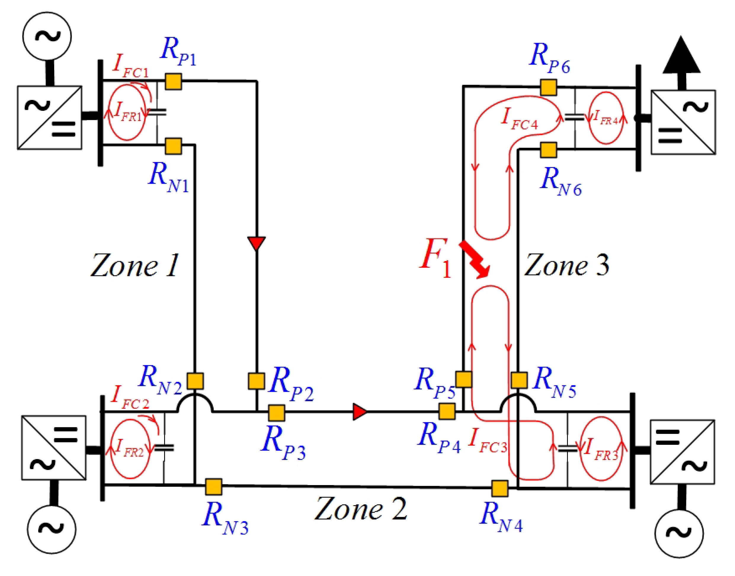
Figure 1. Analyse of FCFH current flow for an external fault in VSC-MTDC grid.
Energies 12 01010 g001
Figure 2. Analyse of FCFH current flow for an internal fault in VSC-MTDC grid.
Energies 12 01010 g002
Figure 3. Flowchart of the proposed harmonic-based pilot protection scheme.
Energies 12 01010 g003
Figure 4. Construction of HVDC cable bundle used in simulation cases.
Energies 12 01010 g004
Figure 5. Simulation results for fault I. (a): RP3 current (b): RP4 (c): Instant amplitude for RP3 (d): Instant amplitude for RP4 (e): Instant frequency for RP3 (f): Instant frequency for RP4.
Energies 12 01010 g005
Figure 6. Simulation results for fault II. (a): RP3 current (b): RP4 (c): Instant amplitude for RP3 (d): Instant amplitude for RP4 (e): Instant frequency for RP3 (f): Instant frequency for RP4.
Energies 12 01010 g006
Figure 7. Simulation results for fault III. (a): RP3 current (b): RP4 (c): Instant amplitude for RP3 (d): Instant amplitude for RP4 (e): Instant frequency for RP3 (f): Instant frequency for RP4.
Energies 12 01010 g007
Figure 8. Simulation results for fault IV. (a): RP3 current (b): RP4 (c): Instant amplitude for RP3 (d): Instant amplitude for RP4 (e): Instant frequency for RP3 (f): Instant frequency for RP4.
Energies 12 01010 g008
Table 1. The parameters of the simulated HVDC model.
BusbarVoltage (kV)ParameterValue
Ba-B2380P/Vdc, Q±200 KV, 400 MW, 0 MVAR
Ba-B3380P/Vdc, Q±200 KV, −800 MW, 0 MVAR
B0-F1145P, Q500 MW, 0 MVAR
B0-E1145Vac/f145 KV, 50 HZ
R/X0.1SC Power30 GVA
Table 2. Defined fault cases to apply on CIGRE DCS2 VSC-MTDC grid.
Fault No.Fault ZoneFault TypeResistance (ohm)Location (km From Right Side)Duration (s)
I3P2P150Permanent
II2P2P1100Permanent
III3PP2G50500.5
IV2PP2G501000.5
Table 3. System and algorithm parameter values used in the simulation tests.
Sampling Frequency [kHz]Fault Inception Time [s] f HS [kHz] [35] N HS [20]IMF Number Used [31]
1001.91271
Table 4. Performance of the FCFH protection scheme for case 1.
Fault No.Relay No. I HM ( pu ) N HM ~OperateSample Delay
R P 3 0.00181--
I R P 4 0.00231--
R N 3 0.00121--
R N 4 0.00121--
R P 3 1.05729+2
II R P 4 1.189829+1
R N 3 0.869728+2
R N 4 0.965928+1
Table 5. Performance of the FCFH protection scheme for case 2.
Fault No.Relay No. I HM ( pu ) N HM ~OperateSample Delay
R P 3 0.0011--
III R P 4 0.00151--
R N 3 0.00111--
R N 4 0.00191--
R P 3 0.940536+3
IV R P 4 0.954731+3
R N 3 0.10079--
R N 4 0.10096--
Table 6. Sensitivity analysis for internal fault scenarios of zone 2.
F. No.ZoneTypeDurationImpedanceLocationRelay I HM ( pu ) Sample Delay
V2P2PPermanent11 R P 3 0.70456
R P 4 1.34520
R N 3 0.70456
R N 4 1.34410
VI2P2PPermanent150 R P 3 0.80014
R P 4 1.26451
R N 3 0.79943
R N 4 1.26401
VII2P2PPermanent1150 R P 3 1.24561
R P 4 0.85643
R N 3 1.11502
R N 4 0.82163
VIII2P2PPermanent1199 R P 3 1.29801
R P 4 0.76034
R N 3 1.44561
R N 4 0.69546
IX2P2PPermanent0.1100 R P 3 1.35691
R P 4 1.35601
R N 3 1.30221
R N 4 1.30240
X2P2PPermanent1100 R P 3 1.12542
R P 4 1.13561
R N 3 1.11871
R N 4 1.11881
XI2P2PPermanent100100 R P 3 0.95782
R P 4 0.95802
R N 3 0.95463
R N 4 0.95552
XII2P2PPermanent500100 R P 3 0.69803
R P 4 0.71723
R N 3 0.69684
R N 4 0.69544
Table 7. Comparison of detection delay time with other literature studies.
ReferenceUsed
Method
Detection Time
Delay (ms)
DCCB Delay
Included
Considerations
[15]ANN4.5The fault localization time delay is 26 ms
[39]DWT0.0375-Used for 2-level VSC-MTDC
[40]TW5Including operating time for DCCB
[41]Transient1.74-Time delay varies for different fault scenarios
[42]S-transform2-1 ms communication delay should be added
[43]TW3DWT is used for TW detection
[44]ROCOV<0.2-2 ms for DCCB should be added
[45]Transient1-The method uses distributed optical sensors