1. Introduction
The transition to a renewable, climate-friendly energy system requires increased flexibility on the supply-and-demand side of industrial processes, while at the same time increasing energy efficiency. An essential contribution to achieving these objectives is the coupling of different sectors (electricity, gas, heat, etc.) to an optimised overall energy supply. In general, the supply does not always follow the simultaneous consumption of an industrial production process. The challenge of utilising any form of energy, be it thermal, mechanical, chemical, or electrical [
1], is enormous. Various types of energy storage systems can make a significant contribution to solving this problem. To achieve this goal of higher flexibility through the integration of storage facilities into the process, it is therefore necessary to answer the questions about the boundary conditions of the storage facility in the process to be optimized with regard to the charging and discharging duration, the type of energy to be stored (e.g., electrical energy or thermal energy), grid connection, space conditions, and output before choosing the storage facility [
2,
3].
In industrial processes, which consume 25.9% of the energy produced throughout Europe [
4], there is great application potential for thermal energy storage, since around 66% of the energy used in the industry flows into the production of process heat at different temperature levels [
5]. Industrial processes are very diverse, and subject to various stationary and transient processes due to the individually produced product. Thermal energy storage systems ensure a more efficient use of process heat by smoothing out load cycles and evening peak loads, and utilizing waste heat [
6]. While the use of latent heat thermal energy storages (LHTES) is more established in building-, food- and medical-technology applications nowadays [
7], the full integration of latent heat storage systems into industrial processes is still in the process of being researched/is in the development phase, up to the prototype stage.
Mathematical methods for the simulation and optimization of storage systems can therefore make a significant contribution to ensuring an efficient and targeted design that utilises its full potential. Jian et al. [
8] optimized a form of solid sensible thermal energy storage with a tubular heat exchanger. For a given fluid outlet temperature and provided energy, the number of heat transfer pipes, length of the storage, mean velocity inside the heat transfer pipes, and the ratio between the inner and outer storage diameter were optimized by reducing storage costs. The problem was solved with a genetic and sequential quadratic programming algorithm provided from the MATLAB optimization toolbox. Beck and Hofmann [
9] presented the optimization of a pressurized water storage tank by using a quadratic cost function depending on the maximum storage temperature and storage volume. In the cost function, mass specific storage vessel material costs which considered manufacturing costs were used. An iterative step-by-step approach to find the optimal design in terms of costs of a molten salt storage was shown by Gabbrielli and Zamparelli [
10]. Besides the storage and insulation size, the shape of the roof was also optimized during the design procedure.
Ruths steam storages (RSS) are industrially well-established as they enable the process steam to be stored and made available for the production process (e.g., paper mill, steel production, food industry) at a later point in time [
11]. An advantage of the traditional RSS is its high rate of charge and discharge over time. In order to increase the energy efficiency of RSS and to enable power-to-heat applications in industrial steam processes, a hybrid storage concept was developed [
12,
13,
14,
15]. This includes the encapsulation of a conventional RSS with a LHTES, where the LHTES device can also be electrically heated as an alternative. Different phase change materials (PCMs) with different phase change temperatures can also be used to obtain the appropriate storage characteristics for the specific application. Conventional RSS are also referred to as gradient-steam storages, because they change their internal pressure when the process steam is injected and extracted. Since the RSS contains a two-phase mixture of liquid water and steam, the temperature of the storage is directly dependent on the pressure. Due to the different pressure levels of the storage tank in the full and empty state, there is a temperature difference between these two states which can reach into the three-digit range. LHTES consist mainly of PCM. Since PCMs can store and provide large amounts of heat in low temperature ranges due to phase change processes, it tries to increase the storage capacity of RSS by means of LHTES units attached to the vessel wall at the outer side of the pressure vessel. Furthermore, the application of the concept to existing steam storage tanks and to newly planned ones is considered.
Different combinations of RSS with PCM are mentioned in the scientific literature. The arrangement of PCM inside the RSS pressure vessel was mentioned by Steinmann and Eck [
16], Buschle et al. [
17], and Tamme et al. [
18]. Another approach to extending existing RSS is to use a tube register which is surrounded by PCM [
17,
18]. The tube register is therefore connected to the RSS, which acts as a reservoir and a separator. LHTES with water/steam as a heat transfer medium, which makes a phase change during charging and discharging, is often mentioned in combination with direct steam generation systems in the literature [
18,
19,
20,
21,
22]. A disadvantage of LHTES is the low thermal conductivity of most PCMs, and therefore, the limited heat-transfer rate inside the PCM. Different methods to realizing a higher level of heat transfer between the heat transfer fluid and the PCM have been investigated in the scientific literature. Xu et al. [
23] presented the possibility of increasing heat transfer by combining porous media with PCM. A thermal conductivity of 20 Wm
was reached with a graphite-salt composite of 15–20% wt graphite, which was also mentioned by Acem et al. [
24]. The usage of a graphite matrix filled with PCM was discussed by Marín et al. [
25]. The application of fins is also a method used for improving the performance of LHTES by increasing the heat transfer area between the PCM and the heat transfer fluid. For example, Laing et al. [
19] discussed this approach by finite element modelling and practical investigations. Also, Gharebaghi and Sezai [
26] discussed fin arrangements in their paper. Steinmann and Tamme [
27] presented a sandwich configuration, in which there was an alternating arranged PCM and a thin layer of material with high thermal conductivity. They also mentioned the usage of macro-encapsulation.
The industries that consume the most steam are in Austria, and for those, the types of hybrid storage which are particularly relevant are pulp and paper, chemicals and petrochemicals, and food and iron/steel production. However, the question arises as to whether such a component can be meaningfully designed to optimally fill and improve the supply and consumption of a process. Since it is not only the two-phase storage which is considered here, there is also the requirement of combining an LHTES with different time constants at the same time. This results in an optimization problem where the trade-off of capital expenditure (CAPEX) for the investment of the hybrid storage and operational expenditure (OPEX) for the cost savings in the process must be evaluated.
In the next section of this contribution, a non-linear optimization model for estimating the investment costs of a hybrid storage system is developed. Results of the optimization model for two different use cases compared to an optimized RSS system are presented in
Section 3. Moreover, a possible design for the real implementation of such a hybrid storage is derived in
Section 4. In
Section 5, economic analysis for the retrofitting of already implemented RSS vessels to hybrid storage vessels is discussed.
2. Optimization Model
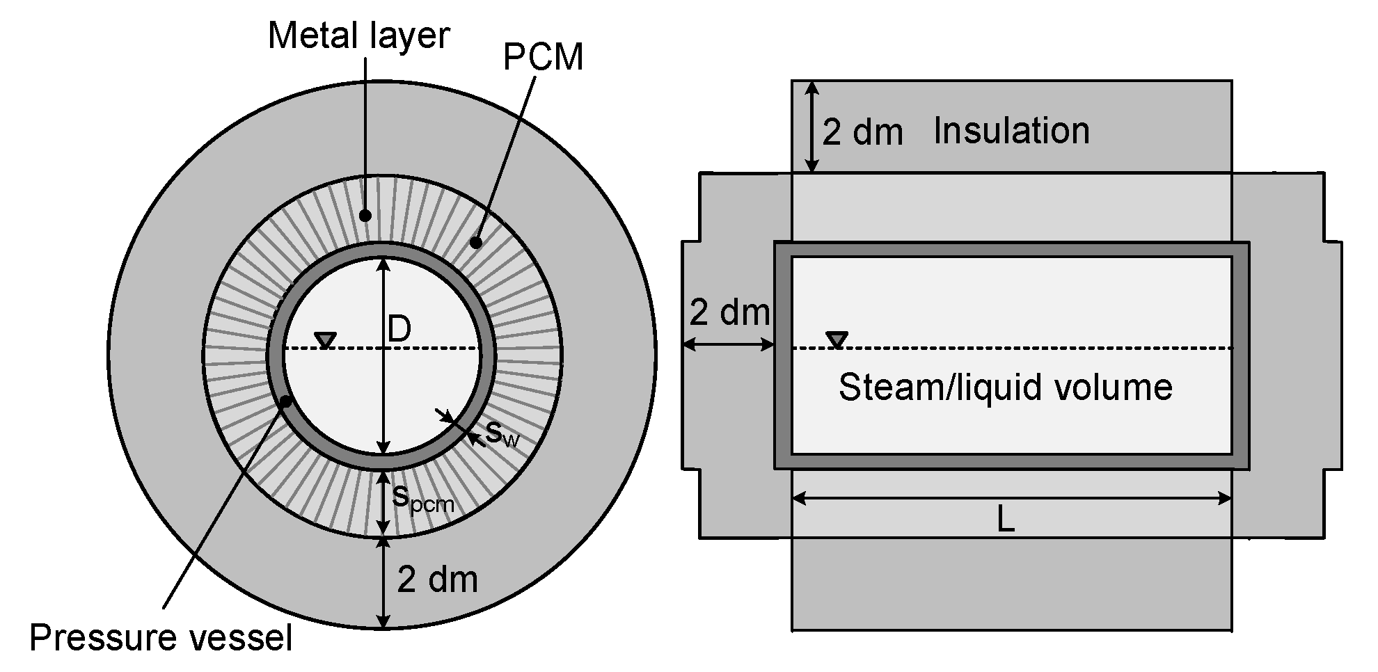
As a first step, a non-linear optimization model for designing a hybrid storage system will be presented in the following. In
Figure 1, the simplified storage geometry is shown. The pressure vessel was assumed as a cylinder with plane side faces. At the shell surface of the pressure vessel, a layer consisting of PCM and a highly thermally conductive material was arranged. A volume of highly thermally conductive material was used to increase the thermal conductivity of the PCM, where an ideal mixture of the two materials was assumed. The pressure vessel and the PCM/highly thermally conductive material layer is surrounded with an insulation layer of 2 dm thickness.
The model was created in MATLAB with the Optimization Toolbox [
28]. For solving the optimization problem, the
GlobalSearch algorithm was applied, which uses the local solver
fmincon. In this algorithm, several start points were used to increase the possibility of finding a global optimum. The start points were generated with a scatter search algorithm, where the first starting point had to be given. The designing tool was developed to find an optimal design of the hybrid storage system.
2.1. Storage Design Estimation Procedure
Before designing the storage component, the requirements had to be defined. First of all, maximum stored energy is needed, and the maximum and minimum allowable pressure for the storage component also must be known. The minimum pressure inside the liquid/steam volume is determined by the pressure level needed in the following industrial process. This pressure should be slightly higher to ensure a sufficient steam supply. The maximum pressure for the pressure vessel design is determined by the pressure of the charging steam. Furthermore, it was assumed that the liquid fill level at the maximum load state is predefined. The liquid fill level describes the ratio between liquid and total volume of the two-phase fluid. The value of the maximum fill level should be chosen while ensuring the steam quality needed for the following process, which means that a liquid water content in the discharging steam should be avoided. With the given liquid fill level and maximum pressure, the two-phase fluid at a maximum load state is defined. Moreover, a maximum time must be specified. This time is used to limit the maximum phase change time of the PCM. For example, the minimum of the charging and discharging time can be selected as the maximum time.
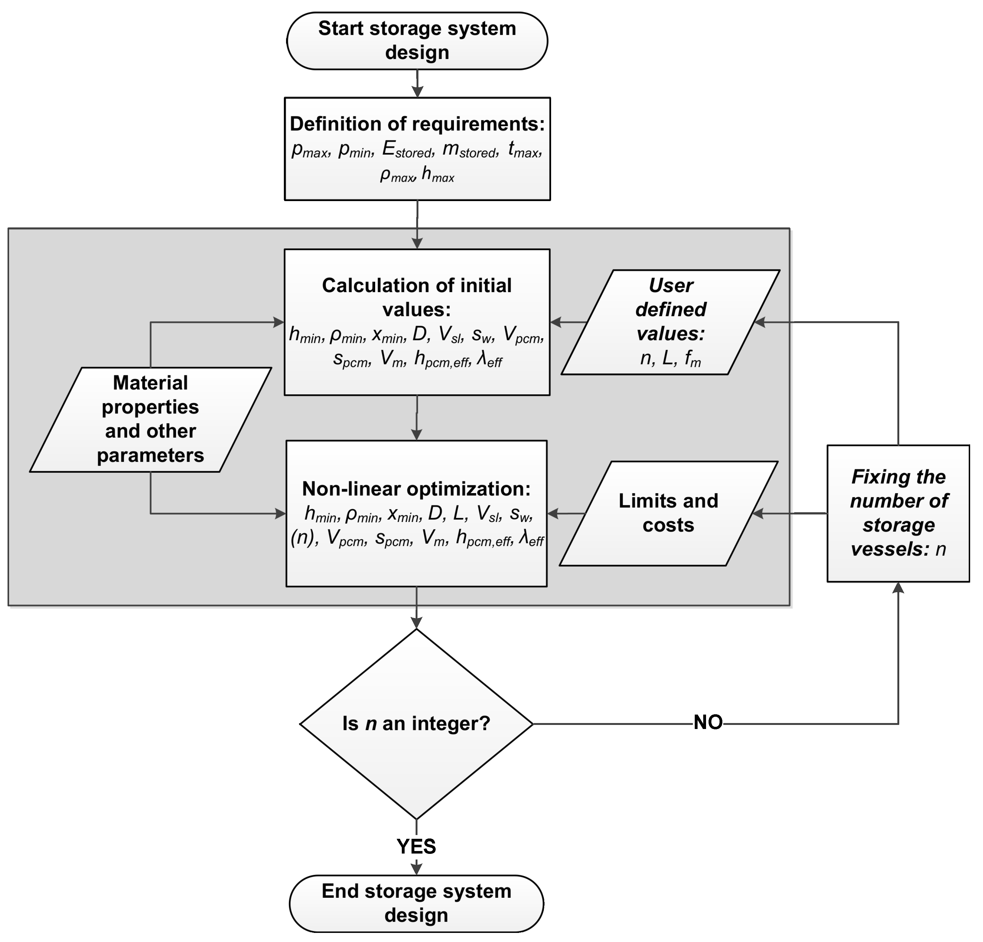
In
Figure 2, the procedure for evaluating an optimal storage design is presented. As it can be seen, after defining the storage requirements, a starting point is calculated, which will later be described in detail. After the start point is defined, the non-linear optimization is performed in the next step.
The optimization variables used in the model are summarized in
Table 1. The upper and lower bounds used in the model are also given in this table. As it can be seen in
Table 1, the number of storage vessels
n are also defined during optimization. Several storage tanks are then usually implemented into the process in the form of a storage line. However, since the optimization for this variable does not have to result in an integer value, two additional optimization runs are performed. Therefore, the number of storage vessels is fixed to an integer value by setting the corresponding upper and lower bound. For these two further optimization runs, the rounded up and down value for the number of storage tanks resulting from the first optimization run was used.
2.2. Constraints
The optimization model consists of equality and inequality constraints. First of all, the equality constraints are presented. The volumes of the different storage parts were calculated using Equations (
1) and (
2).
In Equation (
2), the side walls are neglected because no PCM is arranged at the side faces; only the shell surface is surrounded by PCM. Therewith, the effective thermal conductivity of the ideal PCM/highly thermally conductive material mixture can be approximated by:
It was also assumed that the density of the mixture is equal to the density of the PCM. Therefore, the effective specific latent heat capacity was calculated as follows:
and used later to determine the phase change time. The phase-specific properties of the two phases at minimum pressure inside the pressure vessel are determined by using the CoolProp library [
29]. With the phase-specific properties and the Equations (
5) and (
6), the properties of the two-phase fluid at minimum pressure could be calculated:
The mass balance equation was applied to calculate the needed liquid/steam volume, as follows:
The first inequality constraint used in the optimization model was the energy balance equation (Equation (
8)), meaning that the defined total stored energy was less than or equal to the sum of the energy stored in the liquid/steam volume, PCM volume, and highly thermally conductive material volume. The energy stored in the PCM is equal to the sum of the sensible and the latent stored energy. Depending on the operation strategy, the stored sensible energy will be lower in reality because there will be no temperature balance between the liquid/steam volume and the PCM volume at any time. This also applies to the amount of sensible stored energy in the highly thermally conductive material volume. The energy stored in the pressure vessel wall volume will be neglected. Also, heat losses to the surrounding of the storage vessel was neglected in the optimization model, due to its low impact in contrast to the total stored energy.
The low thermal conductivity of the most PCMs limits the performance of the PCM part of the hybrid storage component in terms of time-constant. The right side of Equation (
9) is a quasi-stationary approximation of the solidification time for a cylinder surrounded by PCM, which, for example, is presented in Baehr and Stephan [
30]. The phase-change time calculated with this equation must be lower or equal to the defined maximum time.
This equation is valid under the following assumptions:
At the initial state, the whole PCM is liquid and the temperature is equal to the phase-change temperature;
The PCM properties are constant and equal for the solid and liquid phase;
Inside the PCM, only heat conduction is taken into account;
The sensible energy is neglected;
The temperature of the heat source is constant.
Contrary to the assumptions presented above, the sensible stored energy was considered in the energy balance equation (Equation (
8)), which led to an underestimation of the complete phase-change time. In addition, the heat source corresponds to the two-phase fluid in the pressure vessel whose temperature is not constant during operation. Therefore, a constant temperature or temperature difference was chosen in order to get realistic results. This will be described in
Section 3.2. With Equations (
9) and (
10), the highly thermally conductive volume was determined.
In the steam/liquid volume, a minimum liquid fill level was used. This resulted in the following inequality constraint:
To ensure the storage geometry would be designed as a horizontal cylinder, a minimal value for the length diameter ratio was given by:
The minimum required wall thickness of the pressure vessel was calculated using Equation (
13). The equation applies to vessels where the ratio of outer to inner diameter is less than or equal to 1.7, and is presented, for example, by Wagner [
31].
Therein, the factor
z denotes the weld seam factor, which was set to 1 for the examples examined in this article. For safety reasons, the maximum pressure used to calculate the minimal wall thickness was increased by 1 bar. The allowable stress is the minimal value of the 20%-yield strength and the mean tensile strength divided by a safety factor each defined as follows, where the safety factors were taken from Wagner [
31],
2.3. Cost Function
The objective of optimization is to minimize the total investment cost of the storage system. The cost function consists of the costs of: (1) the pressure vessel material, (2) the phase change material, and (3) the highly thermally conductive material, as well as (4) other costs. Highly thermally conductive material, such as aluminum or graphite, can be chosen. In examples presented in the following chapters, aluminum was chosen as a highly thermally conductive material. The other costs include insulation, transport, and assembly costs. In
Table 2, some practical experience values for the costs of classical Ruths steam storage vessels are presented.
Based on the values given in
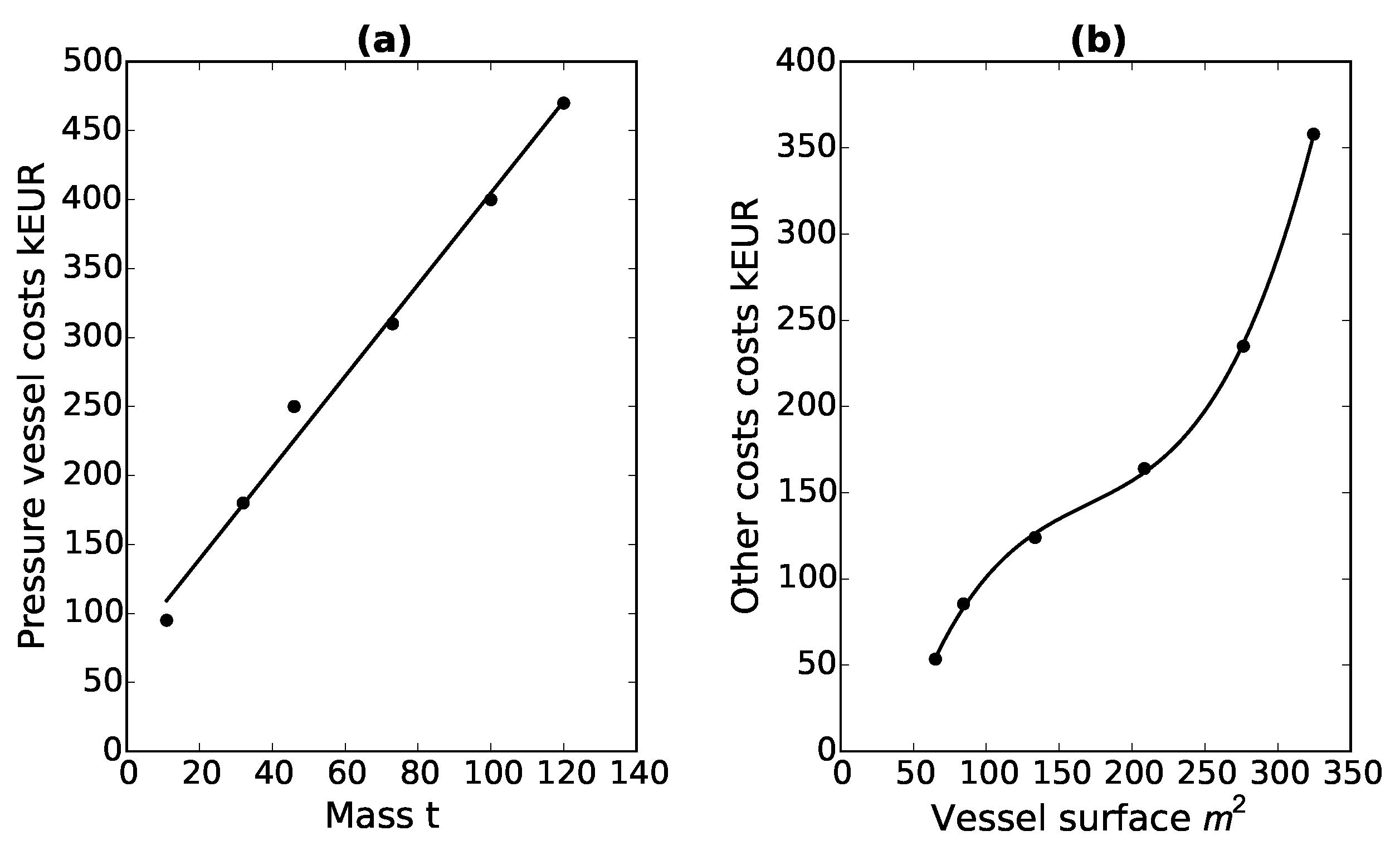
Table 2, a linear approximation function for the pressure vessel costs depending on mass was derived (Equation (
15)). The approximation function and the practical experience values are shown in
Figure 3a.
The mass of the pressure vessel used in Equation (
15) was assumed to be equal to the steel mass and was calculated with Equation (
16):
Figure 3b shows some practical experience values and the corresponding approximation function (Equation (
17)) for the other costs as a function of the storage surface area. This approximation function is a third-order polynomial equation.
It must be pointed out that the cost function for the other costs was derived from experience values for RSS vessels. The hybrid storage surface used in the cost function was calculated by Equation (
18). Therein, the PCM layer thickness was also considered.
The maximum deviation between the practical experience values and the approximation function of the pressure vessel costs is calculated with 15%. For the approximation function of the other costs, a maximum deviation of 2% will be realized. The coefficients of the approximation functions Equations (
15) and (
17) are given in
Table 3.
The cost coefficient used for considering the costs of the PCM
and the highly thermally conductive material
in dependence on the mass was calculated based on the costs of
-
and aluminum by Laing et al. [
32]. These cost coefficients are also shown in
Table 3.
The entire cost function used in the design tool was finally defined as follows:
As previously mentioned, the design tool also takes into account the fact that more than one storage vessel may be considered to optimally meet the process requirements. Therefore, the number of storage vessels
n also occurs explicitly in the cost function (Equation (
19)).
2.4. Ruths Steam Storage Design
RSS design optimization is applied using a reduced hybrid storage model that does not take into account the constraints and variables affecting the PCM portion. This means that in the energy balance equation (Equation (
8)) and the cost function (Equation (
19)), the terms concerning the PCM and the highly thermally conductive material mass do not occur. Thus, the used variables are reduced to 8 and the last five optimization variables in
Table 1 do not occur in this model. Therefore, Equations (
2) to (
4) and Equations (
9) and (
10) are not needed for the design optimization of the RSS system. Therefore, the optimized hybrid storage system can be compared with an optimized RSS system.
2.5. Model Verification
For the plausibility-check of the results, a developed dynamic model of the hybrid storage component was used. This model was created in Modelica/Dymola Version 2015 FD01 [
33] with the TIL 3.3-library (library for thermal components and systems) [
34] and is similar to the model presented by Dusek and Hofmann [
12,
13]. An extended version of the hybrid storage model and the validation of the RSS part with measurement data from an industrially applied RSS system is presented by Dusek and Hofmann [
14]. However, the model used in this article differs in the type of modelling, especially of the PCM part. The PCM volume was therefore divided into several equal volumes in the radial direction. For the following examples, the PCM volume is divided in 20 volumes. At the mean diameter of each volume, there is a node that takes into account the stored energy for each partial volume. For the heat transfer between these nodes, only heat conduction in radial direction is considered, and this approach was also presented by Mehling and Cabeza [
35]. The stored sensible energy was calculated with:
To determine the latent heat stored inside the PCM partial volume, a function depending on the node temperature was created with Equation (
21). The parameter
e is equivalent to 0.0001 and realizes a very small melting range around the phase change temperature
.
For modelling the two-phase fluid volume, both the energy and mass balance equations are needed. With the TILMedia 3.3-library [
34] the properties of the two-phase fluid can be calculated at any time-step. The pressure vessel wall and the insulation layer are also considered in the model. In all these layers, only heat conduction is considered as the heat transfer mode. At the outer diameter of the insulation layer, the heat flow is set to zero; therefore, the heat loss to the environment is neglected.
Depending on the temperature difference between the liquid/steam volume and the surrounding wall, different heat transfer coefficients are used for each phase in the liquid/steam volume. If the temperature of the surrounding wall is lower than the temperature of the liquid/steam volume, the steam condenses at the wall. Therefore, a heat transfer coefficient for condensing steam is used. For the liquid phase, a heat transfer coefficient for liquid water was used in this case. These heat transfer coefficients occur, for example, during charging. During discharging, the temperature of the surrounding wall is higher than the temperature of the liquid/steam volume. Therefore, the liquid water will evaporate, and a corresponding heat transfer coefficient is selected. Moreover, a corresponding heat transfer coefficient is also used for the steam phase. This results in four different heat transfer coefficients which must be given. In this model, a mean heat transfer coefficient between the two occurring heat transfer coefficients is calculated as a function of the current liquid fill level.
3. Use Cases
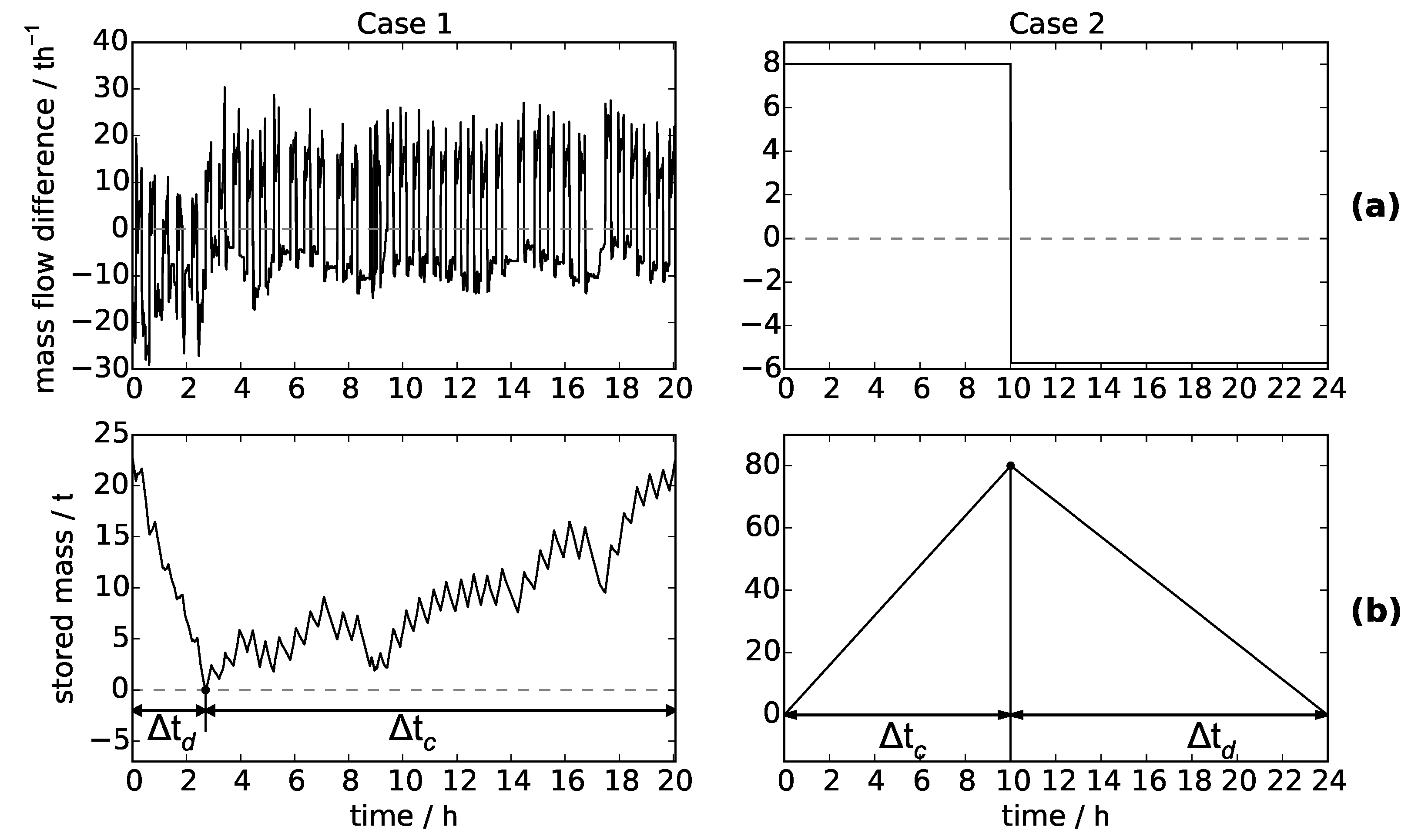
The optimization model was tested for two very different use cases. It is assumed that a typical charging/discharging cycle for the storage system which should be integrated into the process is given for both cases. In the first case (Case 1), the charging and discharging mass flows are not constant. In the second case (Case 2), a constant charging and discharging mass flow is applied. The difference between charging and discharging mass flow at any time and the resulting stored steam mass for both cases are presented in
Figure 4. It shows that in Case 1, the storage system is mostly discharged in the first three hours. This means that the storage system has to be fully charged from the beginning. From the diagrams (below) in
Figure 4 the maximum stored steam mass can be derived, and the assumed charging and discharging times for the PCM part are plotted. In Case 1, it is assumed that small fluctuations of charging and discharging demands are covered by the liquid/steam volume part. The PCM part is used to cover the long-term charging and discharging demand. The time which is used in the designing tool is the minimum value of the charging and discharging time. For Case 1, the discharging time is used, whereas the charging time is more critical in Case 2. At Case 2, the stored mass and also the maximum time is significantly higher when compared to Case 1.
In
Table 4, the pressure of the charging steam is given. In the examples, the specific enthalpy of the charging steam is set constant and equal to the specific enthalpy of dry saturated steam at the charging steam pressure. For safety reasons, the maximum pressure for the storage vessel was set 0.5 bars lower than the charging steam pressure.
The values for the maximum stored mass, as well as the additionally assumed parameters for both cases are summarized in
Table 4.
The specific enthalpy of the discharging steam decreases with the pressure reduction. The maximum stored energy is calculated by multiplying the maximum stored mass by the specific enthalpy of the charging steam. All used properties’ values of the applied materials are shown in
Table 5. Also, the four heat transfer coefficients used in the models are given. On the contrary to the verification model, in the design optimization model a constant heat transfer coefficient is used. In these examples, depending on whether the charging or discharging time is shorter, the corresponding heat transfer coefficients (
Table 5) were used to form a heat transfer coefficient weighted to the given maximum liquid fill level, which results in a heat transfer coefficient of 851.5 Wm
for Case 1, since the discharged is in the foreground here. In Case 2, the loading time is shorter, so a heat transfer coefficient of 1345 Wm
was used.
3.1. Initial Condition and Limits
The limits which were used to design the hybrid storage system are presented in
Table 6. As mentioned above, the stored mass in Case 2 is higher than in Case 1. Therefore, the maximum number of storage vessels chosen was higher for Case 2 than for Case 1.
The non-linear optimization problem was solved using the MATLAB
GlobalSearch algorithm. The start values for the optimization variables can be defined, where the calculation of the start values is done by assuming the aluminum content and the number of storage vessel equal to the corresponding upper limit. Also, for the storage length, a value of 15 m was assumed. With the assumed values and Equations (
1)–(
10) and (
13), the initial values for all optimization variables were calculated using the MATLAB function
fsolve. The same was done for designing the Ruths steam storage vessel with the corresponding simplifications.
3.2. Results
Different fractions of the maximum-occurring temperature difference were tested. In the event of charging, the maximum temperature difference is equal to the difference between the maximum temperature in the steam/liquid volume and the phase change temperature. For discharging, the difference between the minimum temperature inside the liquid/steam volume and the phase change temperature was used as maximum temperature difference. In
Table 7, the optimization results for both cases and different temperature fractions are presented. The adjustment of the temperature difference was also used to correct the error that occurs due to the assumption that the PCM has a phase change temperature at the beginning (Equation (
9)). Contrary to this assumption, the PCM must first be heated or cooled to the phase change temperature which also needs time. In
Table 7, the optimization results for both cases and different temperature fractions are presented. It can be seen that the result for the number of storage vessels is not an integer value after the first optimization run for all examples. Two further optimization runs were accomplished, whereby the upper and lower bound for the number of storage vessels was set to be equal to the rounded value resulting from the first optimization run.
It should be noted that
GlobalSearch cannot guarantee global optimum. Similarly, neither the second nor the third optimization run must necessarily provide the optimal result for an integer value of the number of storage vessels. An integer value different from the value rounded up or down for the number of storage vessels resulting from the first optimization run could provide lower costs. However,
Table 7 shows that the results of the optimization runs performed with a fixed integer value for the number of storage vessels differ only slightly from the first optimization run in terms of total costs. Therefore, the results are sufficient for a first rough estimation.
For example, in Case 1, the number of storage vessels was calculated with 1.79 for the RSS system after the first optimization run. Therefore, further optimization runs were needed. In the second optimization run, the number of storage vessel should be equal to 1, and in a subsequent third run, equal to 2. In
Table 7, there are no solutions for the second optimization run of Case 1 given. The reason for this is that for all examples of Case 1 in the second optimization run, the number of storage vessel should be equal to 1. For one storage, however, the stored energy or steam mass is too large within the assumed limits. Therefore, in Case 1 only the second optimization run with the assumption of a storage system consisting of two identical storage tanks provides a possible storage vessel design.
In Case 2, the number of RSS storage tanks is 6.3 after the first optimization run. Thus, two optimization runs should be performed with a fixed number of storage tanks of 6 and 7. It turns out that for the RSS system, only the higher number of storage vessels provides a possible design. A system of six RSS vessels is not possible for the assumed storage demand in Case 2. In
Table 7, it is also noticeable that in Case 2, the integer number of storage vessels is very different for the resulting RSS and hybrid storage system. For the RSS system, seven storage tanks seems to be the optimal solution. For the hybrid storage system with a temperature difference fraction of 0.4 and 0.3, five storage vessels provide the lowest cost. The lowest cost for the hybrid storage system with a temperature difference fraction of 0.2 results from six storage vessels. Furthermore, the thicker PCM layer thickness in Case 2 than in Case 1 is also clearly recognizeable. Moreover, the resulting diameters of the RSS pressure vessels are higher compared to the hybrid storage pressure vessels, and the hybrid storage vessels are longer than the RSS vessels. For the same total PCM, the PCM layer thickness decreases with increasing length of the storage vessel.
With the model from
Section 2.5, the geometries resulting from the design optimization are checked for the best result in terms of cost (second or third optimization run) for both cases, whereby these geometries serve as input for the dynamic model. Moreover, with the predetermined charging and discharging mass flows and the necessary input parameters, the simulation results were then checked regarding whether the pressure limits were met. In
Table 8, the maximum deviation of the pressure limits are presented. In this table, the costs, the number of storage vessels, storage system’s total volume, and the cost reduction compared to the RSS system are also shown for the best results.
As it can be seen in
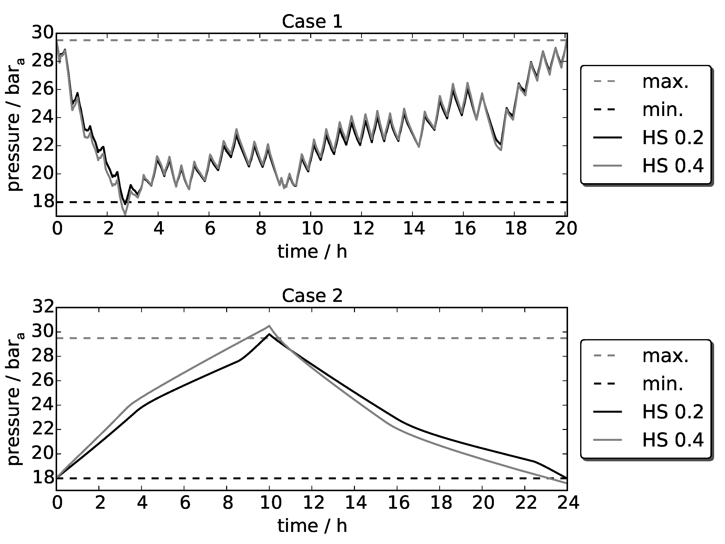
Table 8, the pressure in the hybrid storage systems more or less exceeds or falls below the pressure limit values, depending on the selected temperature difference fraction. This can also be seen in
Figure 5 for both cases. With a temperature difference fraction of 0.4, the pressure drops more clearly compared to a chosen temperature difference fraction of 0.2. The same applies to Case 2. The pressure exceeding it is more critical with a temperature difference fraction of 0.4 than 0.2. For the resulting RSS storage vessels, the pressure inside the vessel never exceeds or falls below the maximum and minimum pressure limits.
In addition, the minimum values for the liquid fill levels resulting from the design tool in the fully discharged state are almost equal to the minimum liquid fill level that occurs during the simulations for all examples.
For Case 1, the cost reduction for a hybrid storage system compared to the RSS system is not as significant as it is for Case 2, and with a selected temperature difference fraction of 0.2, a cost reduction of 20% was reached. The results, presented in
Table 8, also show that the total volumes (without insulation) of the hybrid storage systems are smaller than those of the RSS system, resulting in less space requirements. In Case 2, for the RSS system, one more storage vessel is needed than in the hybrid storage system, with an assumed temperature difference fraction of 0.2. This is advantageous, as each storage vessel requires equipment such as meters and valves, resulting in additional costs. These costs are not included in the cost function. Further investigation is required to identify all cost drivers. In addition, the resulting effective thermal conductivity for each example is listed in
Table 7. The increase is very high compared to the PCM thermal conductivity. Among other things, practical investigations must be carried out for studying the increase of heat transfer in the PCM for a given aluminum content. Depending on these results, the tool has to be adapted. Moreover, the real design of the hybrid storage must be known in order to make a clear statement about the cost advantages of a hybrid storage system over an RSS system.
4. Hybrid Storage Design
Once the mathematically optimized hybrid storage concept with its individual components is determined, the next step is to transfer it to a possible construction design that is practicable for implementation in real industrial applications.
The evaluated optimized hybrid storage component consists of an RSS volume, a highly thermally conductive material volume (layers), and a LHTES volume. The PCM is placed at the inside of small metal containers of the same length as the pressure vessel, meaning that the PCM is not in direct contact with the pressure vessel, which is positive for safety reasons. This introduced the concept of installing an LHTES on the outer shell surface of the pressure vessel, which also enables the possibility of retrofitting existing Ruths-type steam storage systems.
Various PCMs with different phase change temperatures can also be used to obtain the appropriate storage characteristics for the specific application. This means that a single, or even multiple PCMs of different melting temperatures can be used, arranged in a supporting structure. On the one hand, this supporting construction is designed to prevent leakages of the PCM and, on the other hand, to enable the Ruths steam storage to provide the best possible form for press-fit and heat conduction.
4.1. Requirements
In addition to the general requirements on the PCM material selection, special economical, technical, and physical demands were identified for the LHTES with regard to its use in the hybrid storage concept:
Economic requirements: (simple production, modular design, and easy ex-changeability of PCM). This takes into account the simplest possible production of the LHTES in order to reduce production costs. The modular design is necessary in the long term to manufacture the LHTES in large quantities. This requires a design that does not have to be completely specially adapted to every kind of storage geometry. In addition, the hybrid storage concept enables the use of different PCMs. This requirement can be easily met with a modular design. Also, simple exchangeability is required due to the degradation of the PCM and its maximum number of charging cycles—see also [
41]. The subsequent removal of the PCM cells by simple replacement is therefore a necessary condition for keeping costs as low as possible.
Technical requirements: (high elasticity of the PCM shell, resistance of the shell against corrosion by the PCM). The elasticity of the PCM casing is essential to withstand volume expansions during phase change. If this is not considered, the container cover will be subjected to strong cyclic loads, which can fatigue the material and lead to thermal stretching. In addition, the internal pressure changes the characteristics of the PCM, which can lead to a change in the phase change properties. To ensure a long latent-heat storage life, the PCM must be prevented from corroding its shell.
Physical requirements: (good heat transfer between the container and PCM, high thermal conductivity of the PCM). The heat exchange between the water of the liquid/steam volume and the PCM of the LHTES tank should be as large as possible. For this purpose, good heat-conducting casing of the PCM must be used on the one hand, and contact resistance must be minimized on the other. In the present design principle, the use of heat conducting foils is necessary for this purpose. Another essential criterion is the high thermal performance of the PCM. If the thermal conductivity of the PCM is too low, the heat cannot be stored and released quickly enough. This requires the selection of a suitable system to increase thermal conductivity. In addition, the voltage series must be taken into account and prevented when selecting different materials that are in direct contact with each other.
4.2. Consideration Concerning the Hybrid Storage Design
When coupling LHTES with the very fast-reacting RSS units, sufficient heat transfer between the PCM and the associated heat source or heat sink must be ensured. The measures to improve the heat transfer were carried out taking into account their feasibility for the hybrid storage concept. Due to the external mounting of the LHTES on the shell surface of the steam storage, it serves as a heat transfer surface. From the point of view of the LHTES unit, the water in the storage tank itself serves as heat transfer fluid. In LHTES, a heat transfer fluid is used for this purpose, which causes a heat exchange by free or forced convection. The PCM and the heat transfer fluid are usually not in direct contact with each other. Since solid-liquid PCMs are mainly used, the indirect contact prevents mixing of PCM and heat transfer fluid. An ideal simulation with ideal defined phase front within the PCM will deviate from reality. The construction design will decisively determine whether and how the melting front moves through the PCM part of the storage system in each individual container. Depending on the design and gravity, this can lead to multidimensional effects.
If the heat transfer capacity of the LHTES is not sufficiently high, it can be increased by various measures, such as:
Increase of overall heat transfer coefficient: the overall heat transfer coefficient between the water in the RSS and the phase-interface in the LHTES is of great interest for the hybrid storage concept. In addition to the temperature difference, it determines the current heat flow between the two thermal storages. Between water and PCM, the vessel wall and the shell of the PCM is arranged. The container cover of the PCM must be corrosion-resistant and highly thermally conductive. Therefore, alumina is suggested for this purpose, and the resistance of the aluminum to the PCM must be checked. The thickness of the vessel wall of a steam storage depends itself on the diameter as well as the maximum permissible pressure, and is usually made of steel. In the case of thick-walled components, two-dimensional heat conduction phenomena that will influence the heat-affected zone must also be taken into account.
Increase the thermal conductivity of the PCM: numerous methods have been investigated to try and improve the thermal conductivity of PCM. Of the many possibilities for improving heat transfer across the phase change zone that have a high potential for the hybrid storage concept, two are particularly promising in this context: (1) the sandwich concept presented by Steinmann and Tamme [
27], and (2) a composite material. Bayon et al. [
42], carried out experiments with the sandwich concept consisting of graphite foil (1 mm) and PCM (10 mm), whereby significant improvements in heat transport were observed. In the present concept, a combination of aluminum and PCM is preferred for cost reasons to keep the CAPEX as low as possible.
Enlargement of the heat transfer surfaces: Approaches for increasing the heat transfer surface area also provides good results with regard to improving the heat transfer. One option is to increase the heat transfer surfaces by attaching fins. Since the steam storage tank is a pressure vessel which is operated at elevated temperatures, a precise strength analysis of the welded joints must be carried out and the fatigue strength ensured before fins are attached to the inside or outside of the pressure vessel. A strength analysis for welded joints of the external ribs has to be carried out to a different extent when using a sandwich concept, since with this LHTES type, a material connection with the pressure vessel is not absolutely necessary.
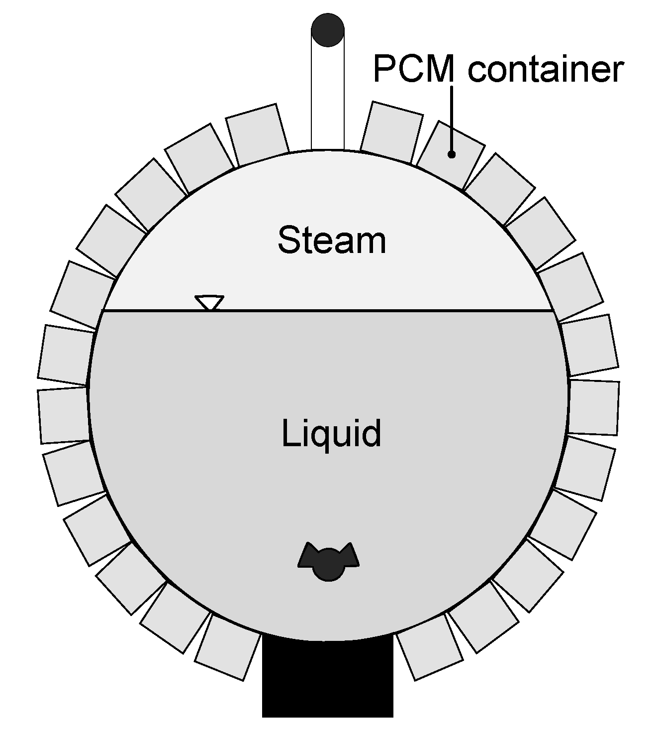
In order to meet the requirements mentioned above for simple production, modular design, and easy exchangeability, a design of the LHTES, as shown in
Figure 6, is proposed. For this purpose, the PCM is arranged in several containers around the RSS. Between the PCM and the RSS, a heat conducting foil is mounted to provide optimal contact resistance. The individual PCM modules are evenly distributed around the circumference. Finally, the hybrid storage (RSS and LHTES) is finished with insulating material and aluminum casing to prevent heat loss to the environment.
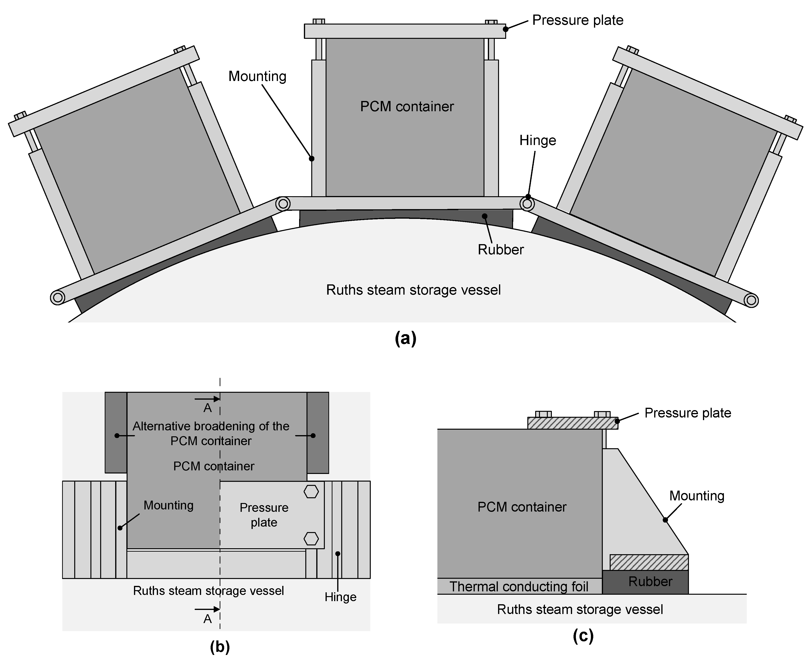
As supporting construction for each of these modules, a design according to
Figure 7 is proposed. For each module, a mounting clamp is provided at both ends. These clamping elements are connected by bolts. For a stable positioned fit of the holder at the surface of the pressure vessel, the deviation has to compensated. The difference in shape between the PCM modules and the outer surface is compensated by a graphite heat-conducting foil (see
Figure 7c). In order to reduce manufacturing costs, a straight-edged design of the PCM modules is provided. Since there are limits between a flat and a curved surface to the compensation of the shape difference by means of thermal conducting foil, the width of the PCM modules must be selected according to the curvature of the cylinder surface. The PCM modules are pressed against the surface of the RSS via the pressure plate. The contact pressure can be adjusted as required by means of the screws. As can be seen in the illustration, two different versions of the PCM modules are possible despite the cuboid shape selected. On the one hand, the PCM modules can be kept as geometrically simple as possible in order to save manufacturing costs, while on the other hand, the PCM modules can alternatively be widened outside the holder (see
Figure 7b, dark grey area) in order to wrap as high a percentage of the outer surface as possible with PCM modules. The implementation of the theoretical ideal design proposal into the direction to reality must be carried out step by step from the calculation to the functional model and further from the test bench to the prototype in compliance with the corresponding safety regulations and must comply with all regulations of the existing strength guidelines, as well as the construction and operating requirements. In addition, the vessels manufactured must fulfil the requirements for approvals, tests, examinations, and inspections.
6. Conclusions
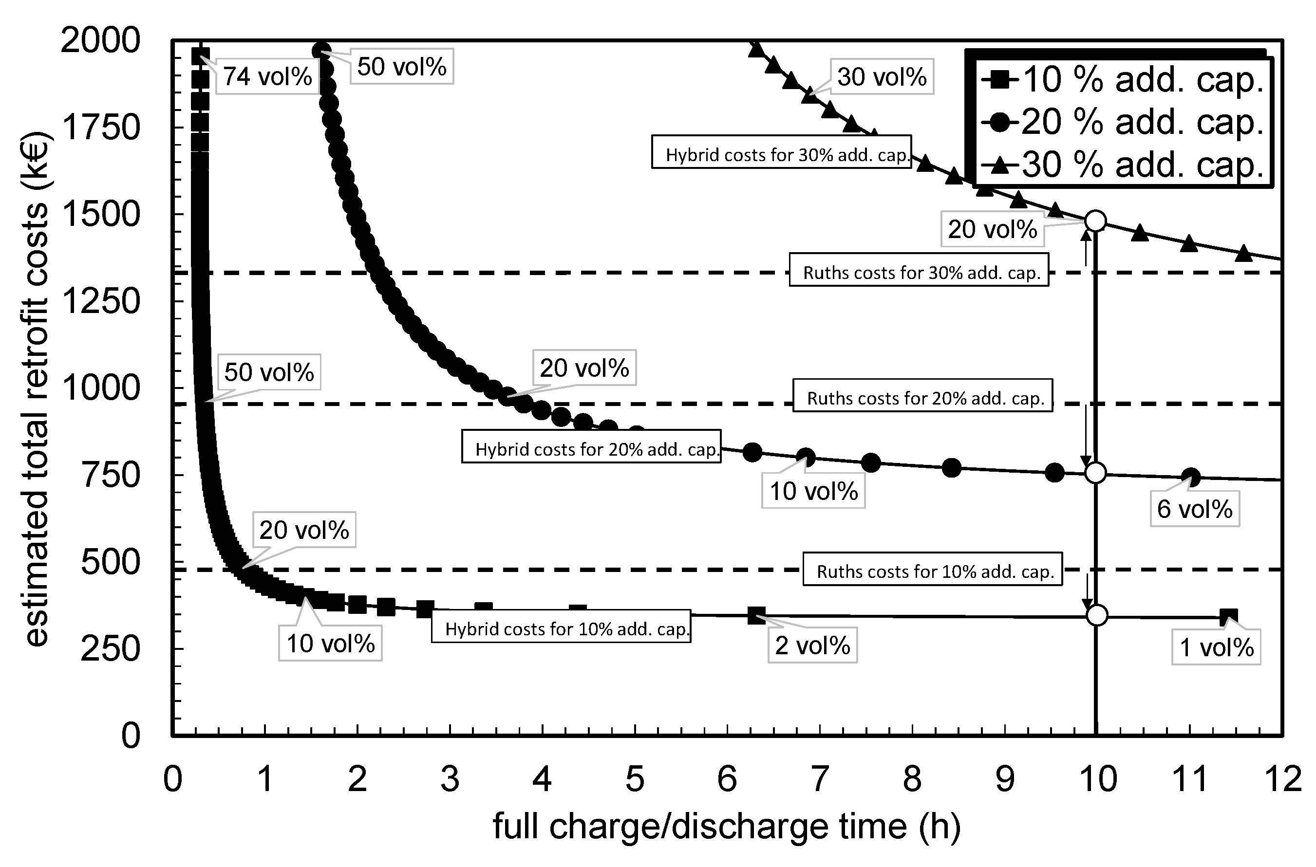
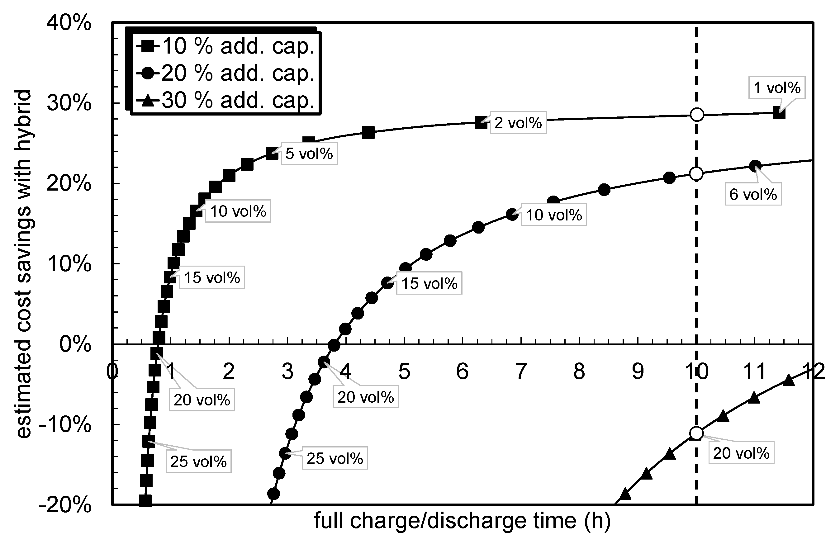
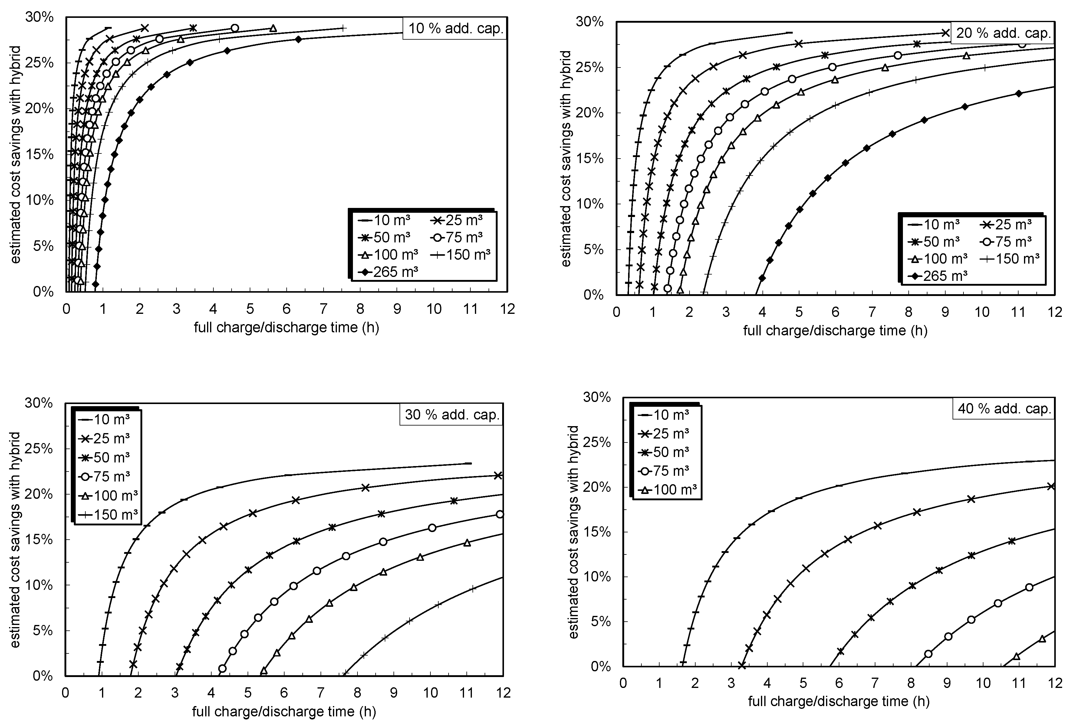
This paper presented the design of a hybrid storage system by non-linear optimization for two different cases. The designed hybrid storage system was compared to a RSS system developed for the same conditions. Under the assumptions used, the results show that the hybrid storage system can be more or less cheaper than an equivalent RSS system. The amount of cost savings depends strongly on the process requirements, particularly on the needed charging or discharging time of the hybrid storage LHTES part. If the charging or discharging time is longer, the hybrid storage system may be cheaper than a comparable RSS system. For example, at a maximum time of 10 h under the assumptions used, where only the material costs for the PCM part of the hybrid storage system are taken into account, a cost savings amount of 20% results. In order to also consider the manufacturing and assembly costs, the actual design of the hybrid storage concept must be known. In this paper, one possible design suggestion for a hybrid storage tank was presented. In addition, an estimation of the benefits of retrofitting existing RSS systems to a hybrid storage system was presented. Therefore, it can be concluded that retrofitting RSS devices with PCM becomes economically more feasible with: long charge/discharge times (e.g., charge/discharge times of 10 h allow for a 150 m storage to be retrofitted with 30% additional storage capacity), small storage sizes (e.g., a 10 m RSS can be retrofitted with up to 40% additional capacity and keep charge/discharge times below 3 h), and small additional storage capacity (e.g., a RSS of any size can be retrofitted with 10% additional capacity and keep charge/discharge times below 1 h).


