A 36-Pulse Diode Rectifier with an Unconventional Interphase Reactor


School of Electrical Engineering and Automation, Harbin Institute of Technology, Harbin 150001, China
*
Author to whom correspondence should be addressed.
Energies 2019, 12(5), 820; https://doi.org/10.3390/en12050820
Submission received: 19 January 2019
/
Revised: 22 February 2019
/
Accepted: 24 February 2019
/
Published: 1 March 2019
Abstract
:This paper proposes a simple 36-pulse diode rectifier with an unconventional interphase reactor (IPR) and single-phase full-wave rectifier (SFR). The primary winding of the unconventional IPR is double tapped and the secondary winding is connected with SFR. The operation mode of the unconventional IPR is analyzed, and the optimal tap ratio and turn ratio of the unconventional IPR are designed from both viewpoints of input line current and load voltage. With the optimal parameters of the unconventional IPR, the proposed rectifier extends the conventional 24-pulse rectifier operation to 36-pulse operation and draws near sinusoidal input line currents, the total harmonic distortion (THD) of which is about 5.035%. The kVA rating of the unconventional IPR is about 2.6% of the output power. Compared with the conventional 36-pulse rectifier with triple-tapped IPR, the proposed 36-pulse rectifier is easy and simple to implement instead of using control circuits. Experiment results are provided to verify the theoretical analysis.
1. Introduction
The multipulse rectifier (MPR) technique is one of the most important and commonly used methods in electrochemical, high-voltage dc transmission, aircraft converter systems, plasma torches, and so on [1,2,3]. MPRs are fed from a three-phase utility resulting in a higher total harmonic distortion (THD) and other power quality problems. Modern MPRs are expected to draw sinusoidal input current form the utility [4]. The MPR pulse number determines the harmonic reduction ability [5], therefore, increasing the pulse number is one of the most effective methods in MPR.
There are two common ways to increasing the pulse number, one is to augment the output phase number of phase-shift transformer, and the other way is to install the auxiliary harmonic reduction circuit at the dc or ac side of the MPR. Presently, the use of 6-pulse/12-pulse MPR-based phase-shift transformers in industrial applications exhibits high THD. Several MPRs with phase-shift transformers are proposed through various phase-shift transformer connections to increase the output number of the phase-shift transformer [6,7,8,9]. These MPR-based phase-shift transformers are of either isolated or non-isolated type with symmetric configurations. An increase in pulse number using an autoconnected transformer is achieved by augmenting the output phases with a suitable phase shift between the output and supply voltages [10,11]. However, with the increasing number of output windings in a phase-shift transformer, the phase-shifting transformer structure becomes complicated and the utilization ratio of turn coils is depressed, causing difficulties in design and manufacture. Because the 12-pulser rectifier is the simplest and the most popular MPR, several circuit topologies with active or passive auxiliary circuits are proposed to install at the dc or ac side of 12-pulse rectifier, which can effectively lower the input line current harmonics [12,13,14,15,16,17,18,19,20,21,22]. The harmonic reduction at the dc-side is carried out by injecting current through an interphase reactor (IPR) [12]. For achieving sinusoidal input current and regulated dc output voltage, a power factor correction circuit connected at the output of uncontrolled rectifiers is presented in [13]. Among the numerous novel auxiliary harmonic reduction circuits, using a multitapped IPR to replace the IPR is the most common approach in harmonic reduction [16,17,18]. When the double-tapped IPR is used, the rectifier can effectively eliminate (12k ± 1)th (k is odd number) harmonics, the theoretical THD of input line current is about 7.6%, and the output voltage is 24 pulses under ideal condition. If the tap number is 3, the MPR needs control circuits and behaves as a 36-pulse rectifier. Though increasing the tap number can improve the pulse number and harmonic reduction ability, the additional diodes or thyristors linked with the taps are in series with the load and the total currents through the additional diodes or thyristors are equal to the load current. The conduction losses of the diodes or thyristors are serious, especially in low-voltage and high-current applications. In [19], a novel 24-pulse rectifier is proposed, in which the proposed IPR is unconventional and different from the multi-tapped IPR. An auxiliary single-phase full-wave rectifier is installed with the secondary winding of the proposed IPR, and the primary winding is central tapped. This modification extends the conventional four-star 12-pulse operation to 24-pulse operation.
In this paper, a 36-pulse diode rectifier with simple circuit configuration and low diode conduction losses is proposed. It consists of a three-phase bridge parallel 12-pulse rectifier, an unconventional IPR, and secondary rectifier circuit. The primary winding of the unconventional IPR and two diodes constitute a conventional double-tapped IPR, which is the first harmonic reduction method. The secondary winding connects secondary rectifier circuit to formulate the second harmonic reduction method. The secondary rectifier circuit is either a single-phase full-wave rectifier (SFR) or a single-phase diode-bridge rectifier. When the unconventional IPR is designed optimally, the proposed 36-pulse rectifier operates normally and simultaneously increases the pulse number of the load voltage and step number of the input line current. The theoretical THD of input current is about 5.035%. Compared with other 36-pulse rectifiers, the proposed rectifier is totally passive components without control circuits, and the conduction losses of the secondary rectifier circuit are very low because of the output of secondary rectifier circuit is connected in parallel with the load. In application, the THD of input line current is less than 4% due to the leakage inductance of autotransformer and inductance of IPR.
2. Proposed 36-Pulse Rectifier with Unconventional IPR
Figure 1 shows the circuit configuration of the proposed 36-pulse diode rectifier. It consists of a delta-connected autotransformer, two three-phase diode-bridge rectifiers, a zero sequence blocking transformer (ZSBT), an unconventional IPR, and a SFR. The delta-connected autotransformer is used to be the phase-shifting transformer. Figure 2a shows the winding configuration of delta-connected autotransformer. Figure 2b shows the phasor diagram of delta-connected autotransformer.
The proposed 36-pulse diode rectifier contains two three-phase diode-bridge rectifiers, the phase-shifting angle of the phase-shift transformer should be π/6 from the viewpoint of eliminating 5th and 7th harmonics [22]. As discussed in [23], when the phase-shifting angle is π/6, the winding configuration of delta-connected autotransformer shown in Figure 2a is the simplest and the delta-connected autotransformer has the least kVA rating. Figure 2b shows the phasor diagram of delta-connected autotransformer. When the delta-connected autotransformer has the simplest winding configuration, the angle α is equal to half of the phase-shifting angle [24]. Therefore, as discussed in [24], the angle is equal to be π/12 and the winding turns of autotransformer in Figure 2 should satisfy:
ZSBT can generate high impedance for three frequency multiplication current to ensure that three-phase diode-bridge rectifier operates independently with 2π/3 conduction of each diode. Because of the delta-connected autotransformer is not isolated, the ZSBT is necessary. The ZSBT exhibits significant impedance for zero-sequence current components, thereby eliminating unwanted conduction sequence of the rectifier diodes in an autoconnected system [5]. As discussed in [5], with a properly designed ZSBT, the voltage across the ZSBT contains only triple frequency components and it impedes the flow of triple harmonic currents to ensure independent six-pulse operation of the two three-phase diode-bridge rectifiers REC I and II. The primary double-tapped winding of the unconventional IPR can absorb the instantaneous difference of the output voltage of the two three-phase diode-bridge rectifiers. The secondary windings of the unconventional IPR have a center tap to install SFR. The ac side of the SFR connects the secondary windings, and the dc side of SFR connects the load. When the double-tapped position and turn ratio of the unconventional IPR meet some condition, the proposed 36-pulse rectifier operates normally.
Figure 3a,b show the tap structure and the winding configuration of the unconventional IPR. The tap ratio αm is defined as:
The turn ratio of the primary and the half secondary windings of the unconventional IPR is:
where NP and NS are the numbers of turn of the primary and half secondary windings of the unconventional IPR, respectively.
3. Operation Mode and Optimal Design of Unconventional IPR
3.1. Operation Mode
In order to demonstrate the operation mode of the unconventional IPR, the following assumptions are given below:
- (1)
- The load of proposed rectifier is a large inductance loading and the load current id can be view as a constant Id.
- (2)
- The leakage inductances and resistances of autotransformer and unconventional IPR are neglected.
- (3)
- Assume that the input voltage of the proposed 36-pulse rectifier is:where Um is the amplitude of the input phase voltage, ω is the angular frequency of the input phase voltage.
- (4)
- Assume that the voltage across the secondary winding of the unconventional IPR is us, and the load voltage is ud. The output voltage of the two three-phase diode-bridge rectifiers is ud1 and ud2, respectively.
The operation mode of the unconventional IPR is determined by the relation of us and ud, and the relation of ud1 and ud2. Therefore, there are four operation modes, as shown in Figure 4:
Mode I: When and , the unconventional IPR operates under mode I, as shown in Figure 4a. In this mode, the diodes of the SFR are reverse-biased and OFF, the current if is equal to zero, and the SFR does not work. Diode Dp of the primary winding is forward-biased and ON, and diode Dq is reverse-biased and OFF. The unconventional IPR operates as a double-tapped IPR. The output currents of the two three-phase diode-bridge rectifiers are:
The load voltage is:
Mode II: When and , the unconventional IPR operates under mode II, as shown in Figure 4b. In this mode, the diodes of the SFR are reverse-biased and OFF, the current if is equal to zero, and the SFR does not work. Diode Dq of the primary winding is forward-biased and ON, and diode Dp is reverse-biased and OFF. The unconventional IPR operates as a double-tapped IPR. The output currents of the two three-phase diode-bridge rectifiers are:
The load voltage is:
Mode III: When and , the unconventional IPR operates under mode III, as shown in Figure 4c. In this mode, diode Dm is forward-biased and turned ON, current im is positive, and it is injected to the load. Diode Dn is reverse-biased and OFF. Simultaneously, diode Dp is ON and diode Dq is OFF. During this time interval, because the load voltage ud is greater than the voltage ud2, the current id2 is equal to zero.
The MMF relationship of the unconventional IPR for this mode is:
According to Kirchhoff’s current law (KCL), the relation among im, if, ip and id is:
Substituting Equations (2), (3) and (9) into Equation (10), Equation (10) is transformed to:
From Equations (9)–(11), the currents id1 and if are obtained as:
According to Kirchhoff’s voltage law (KVL), the voltage ud1 and ud2 meet:
Substituting Equation (3) into Equation (13) yields:
Mode IV: When and , the unconventional IPR operates under mode IV, as shown in Figure 4d. In this mode, diode Dn is forward-biased and turned ON, current in is positive, and it is injected to the load. Diode Dm is reverse-biased and OFF. Simultaneously, diode Dq is ON and diode Dp is OFF. During this time interval, because the load voltage ud is greater than the voltage ud1, the current id1 is equal to zero.
The MMF relationship of the unconventional IPR for this mode is:
The analysis is similar as the mode III, the currents id2 and if are obtained as:
The voltage ud and ud1 are obtained as:
From the above analysis, it is noted that the output currents id1 and id2 of the two three-phase diode-bridge rectifiers under operation modes III and IV are different from that of under operation modes I and II because of the SFR output current. When the parameters αm and αn of the unconventional IPR meet some conditions, the proposed MPR operates as a 36-pulse rectifier and reduces the harmonic in the input line current effectively.
3.2. Necessary Condition
According to the operation mode, if the maximum value of the voltage us is less than the minimum value of load voltage ud, the unconventional IPR operates as double-tapped IPR and the MPR operates as 24-pulse rectifier. In order to make the unconventional IPR operate normally, the following necessary condition should meet:
From Figure 2a,b, the output voltages of the delta-connected autotransformer can be expressed as:
Furthermore, from the modulation theory, the output voltage of the two three-phase diode-bridge rectifiers can be written as:
where Sa1, Sb1, Sc1, Sa2, Sb2, and Sc2 are the switching functions. The switching function Sa1 can be expressed as:
and the relation among the switching functions is:
Therefore, the output voltages ud1 and ud2 can be expressed as:
From Figure 1, the voltage across the primary winding of the unconventional IPR can be calculated as:
According to the definition of αn, the voltage us can be expressed as:
From Equation (26), the maximum of the absolute value of us is calculated as:
Under the operation modes I and II, the unconventional IPR operates as conventional double-tapped IPR and the load voltage ud24 can be obtained as:
from Equation (28), the minimum load voltage is determined by parameter αm, and can be calculated as:
From Equations (18), (27), and (29), it is obtained that:
Therefore, when the parameters αm and αn satisfy the above necessary condition, the unconventional IPR can operate normally.
3.3. Optimal Parameters Design
Actually, the above necessary condition is essential and critical but cannot ensure the proposed MPR operating as 36-pulse rectifier. In this section, the optimal turn ratio of the unconventional IPR is designed in order to ensure the proposed MPR operating as 36-pulse rectifier and minimize the input line current THD.
Assume that the first phase angle when the absolute value of us is equal to load voltage ud to be θ, and it meets:
Since the voltage us is symmetrical and its period is π/6, the phase angle θ meets:
From Equations (26), (28), and (31), the resulting equation is:
Solving the above equation, the first phase angle θ is:
According to the operation mode of unconventional IPR, the output currents of the two three-phase diode-bridge rectifiers can be expressed as follows:
From Figure 1, the input currents of the two three-phase diode bridge rectifiers can be expressed by switching functions as:
In Figure 1 and Figure 2, according to the Ampere turns balance principle and Kirchoff’s current law, it is obtained that:
Substituting Equations (35) and (36) into Equation (38), the input line current ia of the proposed rectifier can be calculated in the time interval of [0, π/2]:
In Equation (39), the input line current ia is obviously dependent on the parameters αm and αn. The time interval of [0, π/2] is selected because the input line current ia is symmetrical and it is sufficient to determine the THD of input line current. We define the THD of the input line current as:
where Ia is the rms value of the input line current ia, I1 is the rms value of the fundamental of the input line current ia.
From Equation (39), the Fourier series of the input line current ia is calculated as:
where Bn meets:
Furthermore, the rms value of the input line current ia is calculated as:
and the rms value of the fundamental of the input line current ia is calculated as:
Substituting (42) and (43) into (40), the THD of input line current ia can be obtained. Figure 5 shows the variation in THD of ia for different parameters αm and αn.
In Figure 5, when the parameter αm and αn cannot satisfy the necessary condition, the proposed MPR operates as 24-pulse rectifier and THD of ia is changing from 7.52% to 15.15% as parameter αm changes. When the necessary condition is satisfied, the proposed MPR operates as a 36-pulse rectifier and THD of ia is changing from 5.035% to 7.52% as parameters αm and αn change. Especially, when αm = 0.1637 and αn = 10.74, the minimum THD of ia is shown to be 5.035%. Under the optimal parameters, the first phase angle θ is obtained as:
According to operation mode of the unconventional IPR and substituting the optimal parameters into Equations (35), (36) and (39), we can obtain the waveform of currents im, in, ip, iq id1, id2 and ia, as shown in Figure 6.
Figure 7 shows the spectrum of input line current ia under the optimal parameters. From Figure 6, the input line current of the proposed rectifier only includes (36h±1) th (h: integer) harmonics and the proposed rectifier behaves as a 36-pulse rectifier under the optimal parameters.
Actually, there is another way to determine the optimal parameters from the viewpoint of the load voltage. According to the operation mode of the unconventional IPR, the load voltage can be divided into four parts. If the proposed 36-pulse rectifier works normally, the load voltage should have 36 pulses with equal width and equal height per power supply cycle. Therefore, assume that the theoretical waveform of load voltage under the optimal parameters shows as Figure 8. In addition, assume that the first phase angle θ is π/18.
From Equation (34), the parameters αm and αn satisfy the equation:
In the interval of [0, π/18], the unconventional IPR operates under mode II and the load voltage ud is expressed as Equation (28). This part of the waveform ud-part1 is different when the parameter αm changes, as Figure 9a shows. The maximum value of Equation (28) can be calculated as:
In the interval of [π/18, 2π/18], the unconventional IPR operates under mode IV. From Equations (17) and (24), the load voltage ud is expressed as:
Furthermore, this part of the waveform ud-part2 is also different when the parameter αm changes, as Figure 9b shows. The maximum value of the load voltage in this interval can be calculated as:
In order to realize the theoretical waveform of load voltage, the Equation (46) should be equal to the Equation (48). From Equations (45), (46) and (48), the parameters αm and αn can be calculated as αm = 0.1637 and αn = 10.74. The results are same as the above analysis from the viewpoint of the THD of the input line current.
3.4. KVA Rating of the Unconventional IPR
From Figure 3b, according to the MMF relationship, the voltage of the primary winding AT, BT’, and TT’ of the unconventional IPR can be expressed as:
From Figure 4, after the unconventional IPR is designed optimally, the output voltage of the two-phase diode-bridge rectifiers can be obtained. The voltage across the primary winding of the unconventional IPR can be calculated as:
From Equation (51), the rms value of the uAB under the optimal parameters is calculated as:
The rms value of the voltage across the secondary winding can be expressed as:
From Equations (35) and (36), according to the operation mode of the unconventional IPR, the rms value of the current through the primary winding AT or BT’ of the IPR can be calculated as:
The rms value of the current through the primary winding TT’ of the IPR can be calculated as:
Furthermore, the rms value of current through the secondary winding of IPR can be calculated as:
Therefore, the kVA rating of the unconventional IPR is calculated as:
3.5. KVA Rating of the ZSBT
As discussed in [5], the voltage across the ZSBT is expressed as:
Furthermore, the rms value of voltage across the ZSBT is calculated as:
Therefore, according to Equations (54) and (59), the kVA rating of the ZSBT is calculated as:
4. Experimental Results
In order to validate the theoretical analysis, an experimental setup with 3 kW is designed. Table 1 shows the rectifier specifications and components.
The input rectifier is from a programmable 61511 AC source (Chroma, Bellows Falls, VT, USA) and the power quality analyzer is a HIOKI 3196 (HIOKI, Ueda, Nagano, Japan).
Under the rated conditions listed in Table 1, Figure 10a shows the input line currents and their THD when the unconventional IPR operating as double-tapped IPR. The proposed rectifier behaves as a 24-pulse rectifier and the input line current THD is about 6.5% which is slightly less than the theoretical value. Because the tapped ratio αm = 0.16 is not the optimal parameter for 24-pulse rectifier with double-tapped IPR, there are also 11th and 13th harmonic components in the spectrum of the input line current.
Figure 10b shows the input line currents and their THD when the unconventional IPR has the optimal parameters. The proposed rectifier behaves as a 36-pulse rectifier and the experimental value of THD is about 4.3%. Whether the unconventional IPR operates as a double-tapped IPR or under optimal condition, the experimental value of THD is less than that of the theoretical value due to the filtering effect of leakage inductance of autotransformer and inductance of IPR and ZSBT. Compared with Figure 10a, the unconventional IPR is effective on reducing harmonic distortion of the rectifier input currents.
Figure 11 shows the measured waveforms. Figure 11a shows the primary diodes currents ip and iq of the unconventional IPR. Figure 11b shows the secondary diodes currents im and in of the unconventional IPR, and the output current if of SFR. Compared with the primary diodes currents, the secondary diodes currents are very small. Figure 11c shows the output currents id1 and id2 of the two three-phase diode-bridge rectifier. The currents id1 and id2 are modulated obviously when the unconventional IPR with optimal parameters. The waveforms of these currents basically coincide with the theoretical analysis in Figure 6. Figure 11d shows the input currents ia1 and ib1 of the three-phase diode-bridge rectifier I (REC I in Figure 1). Figure 11e shows the output voltages ud1 and ud2 of the two three-phase diode-bridge rectifier. Figure 11f shows the load voltage, which are smothered in the experimental results due to the load filtering inductance.
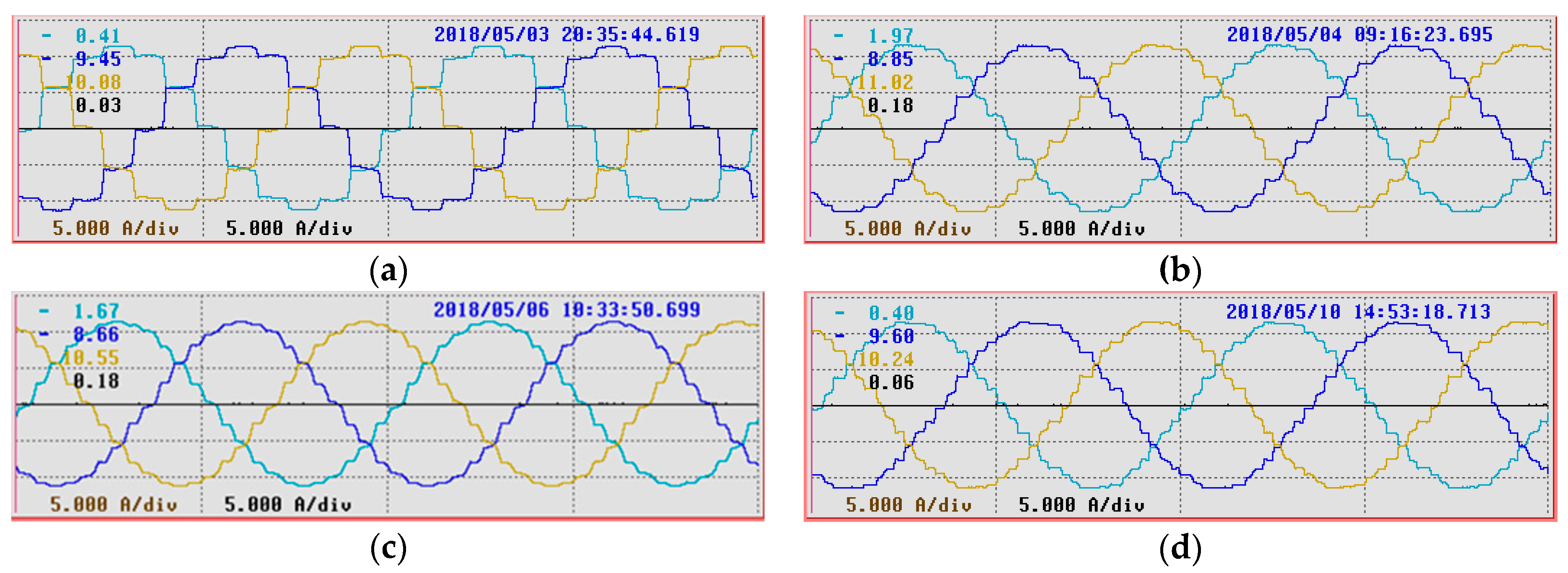
Figure 12 shows the waveforms of input line currents of MPRs under the rated conditions listed in Table 1. Table 2 shows the comparison of input line current THD, IPR kVA rating, load power and efficiency.
From Figure 12a, the input line current of conventional 12-pulse rectifier contains 12 steps with equal width per power supply cycle and the experimental THD is about 12.23%. Figure 12b shows the input line current of 24-pulse rectifier with double-tapped IPR. Compared with Figure 11a, the experimental THD is small because the double-tapped IPR is designed optimally. Figure 12c shows the input line current of 24-pulse rectifier with unconventional IPR designed optimally according to [19]. From Figure 12b,c, the step number of input line currents of both 24-pulse rectifiers is increased from 12 to 24. From Figure 12d, the input line current of proposed 36-pulse rectifier contains 36 steps with equal width per power supply cycle when the unconventional IPR designed optimally. From Table 2, the experimental THD of input line current is decreased as the pulse number of load voltage and the step number of input line current increasing. Though the IPR kVA rating in 24-pulse rectifier with double-tapped IPR is small, the kVA rating of other magnetic components will increase. From the experiment results, the efficiency of proposed 36-pulse rectifier with unconventional IPR is slightly improved.
5. Conclusions
This paper proposes an unconventional IPR to extend the conventional 24-pulse diode rectifier with double-tapped IPR to a 36-pulse rectifier. The primary winding of the unconventional IPR is double-tapped and the secondary winding is connected with SFR. When the unconventional IPR is designed optimally, under ideal conditions, the proposed rectifier operates as a 36-pulse rectifier and draws near sinusoidal input line currents. The operation mode, the optimal parameters and kVA rating of the unconventional IPR are analyzed and derived in this paper. Under optimal parameter conditions, the THD of input line currents is about 5.035% and the current through the secondary winding of the unconventional IPR is very small. Above all, compared with the conventional 36-pulse rectifier using the three-tapped IPR, the proposed rectifier is easy to realize instead of control circuit.
Author Contributions
Under the supervision of S.Y., Y.L. carried out this research work. S.Y. proposed the main idea and analysis method. Y.L. was responsible for the theoretical derivation and manuscript writing. H.B. proposed suggestions and right directions to design the experimental work. W.Y. carried out the simulation and helped Y.L. to perform the experiments.
Funding
This work was supported by National Natural Science Foundation of China (Grant No.51677036).
Conflicts of Interest
The authors declare no conflict of interest.
References
- Rodriguez, J.; Pontt, J.; Silva, C.; Wiechmann, E.; Hammond, P.; Santucci, F.W.; Álvarez, R.; Musalem, R.; Kouro, S.; Lezana, P. Large current rectifiers: State of the art and future trends. IEEE Trans. Ind. Electron. 2005, 52, 738–746. [Google Scholar] [CrossRef]
- Singh, B.; Gairola, S.; Singh, B.; Chandra, A.; Al-Haddad, K. Multipulse AC-DC converters for improving power quality: A review. IEEE Trans. Power Electron. 2008, 23, 260–281. [Google Scholar] [CrossRef]
- Das, J. Harmonic Reduction at the Source; IEEE Press: New York, NY, USA, 2015. [Google Scholar]
- Prakash, P.S.; Kalpana, R.; Singh, B.; Bhuvaneswari, G. A 20-pulse asymmetric multiphase staggering autoconfigured transformer for power quality improvement. IEEE Trans. Power Electron. 2018, 33, 917–925. [Google Scholar]
- Choi, S.; Lee, B.; Enjeti, P. New 24-pulse diode rectifier systems for utility interface of high-power AC motor drives. IEEE Trans. Ind. Appl. 1997, 33, 531–541. [Google Scholar] [CrossRef]
- Abdollahi, R.; Gharehpetian, G. Inclusive design and implementation of novel 40-pulse ac-dc converter for retrofit application and harmonic mitigation. IEEE Trans. Ind. Electron. 2016, 63, 667–677. [Google Scholar] [CrossRef]
- Khan, S.; Zhang, X.; Saad, M.; Ali, H.; Khan, B.; Zaman, H. Comparative analysis of 18-pulse autotransformer rectifier unit topologies with intrinsic harmonic current cancellation. Energies 2018, 11, 1347. [Google Scholar] [CrossRef]
- Singh, B.; Bhuvaneswari, G.; Garg, V. T-connected autotransformerbased 24-pulse AC–DC converter for variable frequency induction motor drive. IEEE Trans. Energy Convers. 2006, 21, 663–672. [Google Scholar] [CrossRef]
- Mon-Nzongo, D.L.; Ipoum-Ngome, P.G.; Jin, T.; Song-Manguelle, J. An improved topology for multipulse AC/DC converters within HVDC and VFD systems: Operation in degraded Modes. IEEE Trans. Ind. Electron. 2018, 65, 3646–3656. [Google Scholar] [CrossRef]
- Yang, T.; Bozhko, S.; Asher, G. Functional modeling of symmetrical multipulse autotransformer rectifier units for aerospace applications. IEEE Trans. Power Electron. 2015, 30, 4704–4713. [Google Scholar] [CrossRef]
- Singh, B.; Bhuvaneswari, G.; Kalpana, R. Autoconnected transformer based 18-pulse ac-dc converter for power quality improvement in switched mode power supplies. IEEE Trans. Power Electron. 2010, 3, 525–541. [Google Scholar] [CrossRef]
- Meng, F.; Yang, W.; Zhu, Y.; Gao, L.; Yang, S. Load adaptability of active harmonic reduction for 12-pulse diode bridge rectifier with active interphase reactor. IEEE Trans. Power Electron. 2015, 30, 7170–7180. [Google Scholar] [CrossRef]
- Biela, J.; Hassler, D.; Schönberger, J.; Kolar, J.W. Closed-loop sinusoidal input-current shaping of 12-pulse autotransformer rectifier unit with impressed output voltage. IEEE Trans. Power Electron. 2011, 26, 249–259. [Google Scholar] [CrossRef]
- Sandoval, J.J.; Krishnamoorthy, H.S.; Pitel, I. Reduced active switch front-end multipulse rectifier with medium-frequency transformer isolation. IEEE Trans. Power Electron. 2017, 32, 7458–7468. [Google Scholar] [CrossRef]
- Young, C.; Chen, M.; Lai, C.; Shih, D. A novel active interphase transformer scheme to achieve three-phase line current balance for 24-pulse converter. IEEE Trans. Power Electron. 2012, 27, 1719–1731. [Google Scholar] [CrossRef]
- Pan, Q.; Ma, W.; Liu, D.; Zhao, Z.; Meng, J. A new critical formula and mathematical model of double-tap interphase reactor in a six-phase tap-changer diode rectifier. IEEE Trans. Ind. Electron. 2007, 54, 479–485. [Google Scholar]
- Meng, F.; Yang, S.; Yang, W. Modeling for a multitap interphase reactor in a multipulse diode bridge rectifier. IEEE Trans. Power Electron. 2009, 24, 2171–2177. [Google Scholar] [CrossRef]
- Singh, B.; Garg, V.; Bhuvaneswari, G. Polygon-connected autotransformer-based 24-pulse AC–DC converter for vector-controlled induction-motor drives. IEEE Trans. Ind. Electron. 2008, 55, 197–208. [Google Scholar] [CrossRef]
- Yang, S.; Wang, J.; Yang, W. A Novel 24-Pulse Diode Rectifier with an Auxiliary Single-Phase Full-Wave Rectifier at DC Side. IEEE Trans. Power Electron. 2017, 32, 1885–1893. [Google Scholar] [CrossRef]
- Chivite-Zabalza, F.J.; Forsyth, A.J.; Araujo-Vargas, I. 36-Pulse Hybrid Ripple Injection for High-Performance Aerospace Rectifiers. IEEE Trans. Ind. Appl. 2009, 45, 992–999. [Google Scholar] [CrossRef]
- Li, X.; Xu, W.; Ding, T. Damped high passive filter—A new filtering scheme for multipulse rectifier systems. IEEE Trans. Power Deliv. 2017, 32, 117–124. [Google Scholar] [CrossRef]
- Paice, D.A. Power Electronic Converter Harmonic Multipulse Methods for Clean Power; IEEE Press: New York, NY, USA, 1996. [Google Scholar]
- Meng, F.; Gao, L.; Yang, S.; Yang, W. Effect of phase-shift angle on a delta-connected autotransformer applied to a 12-pulse rectifier. IEEE Trans. Ind. Electron. 2015, 62, 4678–4690. [Google Scholar] [CrossRef]
- Meng, F.; Yang, W.; Yang, S. Effect of voltage transformation ratio on the kilovoltampere rating of delta-connected autotransformer for 12-pulse rectifier system. IEEE Trans. Ind. Electron. 2013, 60, 3579–3588. [Google Scholar] [CrossRef]
Figure 1.
Schematic diagram of the proposed 36-pulse diode rectifier.
Figure 2.
(a) Winding configuration of the delta-connected autotransformer; (b) Phasor diagram of the delta-connected autotransformer.
Figure 2.
(a) Winding configuration of the delta-connected autotransformer; (b) Phasor diagram of the delta-connected autotransformer.

Figure 3.
(a) Tap structure of the unconventional IPR; (b) Winding configuration of the unconventional IPR.
Figure 3.
(a) Tap structure of the unconventional IPR; (b) Winding configuration of the unconventional IPR.

Figure 4.
Operation modes of the unconventional IPR. (a) Operation mode I; (b) Operation mode II; (c) Operation mode III; (d) Operation mode IV.
Figure 4.
Operation modes of the unconventional IPR. (a) Operation mode I; (b) Operation mode II; (c) Operation mode III; (d) Operation mode IV.

Figure 5.
Variation in THD of ia for different parameter αm and αn.

Figure 6.
Theoretical currents waveforms. (a) Current im. (b) Current in. (c) Current ip. (d) Current iq. (e) Current id1. (f) Current id2. (g) Input line current ia.
Figure 6.
Theoretical currents waveforms. (a) Current im. (b) Current in. (c) Current ip. (d) Current iq. (e) Current id1. (f) Current id2. (g) Input line current ia.

Figure 7.
The spectrum of input line current ia under the optimal parameters.
Figure 8.
Theoretical waveform of load voltage under the optimal parameters.
Figure 9.
The first part and second part of load voltage waveform with different parameter αm. (a) The first part waveform ud-part1; (b) The second part waveform ud-part2.
Figure 9.
The first part and second part of load voltage waveform with different parameter αm. (a) The first part waveform ud-part1; (b) The second part waveform ud-part2.
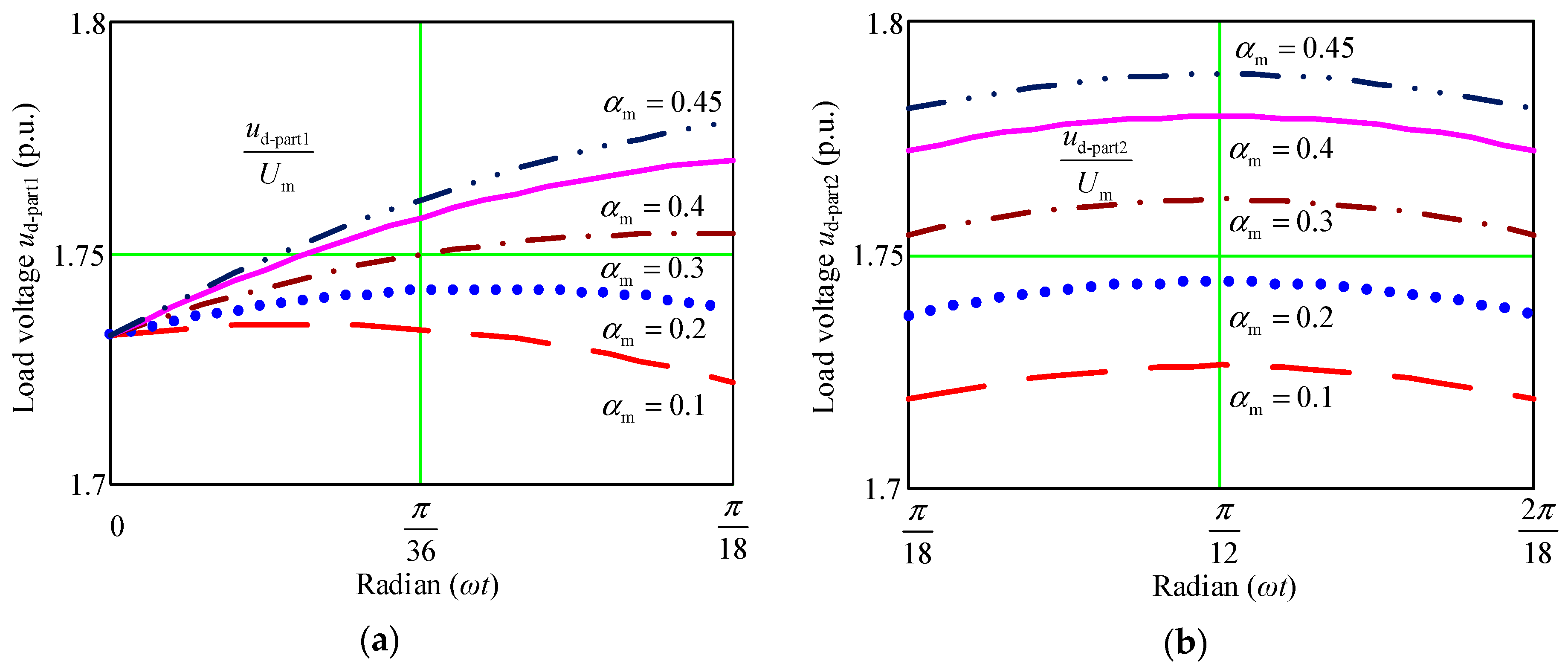
Figure 10.
Input line currents and their spectrums. (a) When the unconventional IPR operating as double-tapped IPR. (b) When the unconventional IPR with the optimal parameters.
Figure 10.
Input line currents and their spectrums. (a) When the unconventional IPR operating as double-tapped IPR. (b) When the unconventional IPR with the optimal parameters.
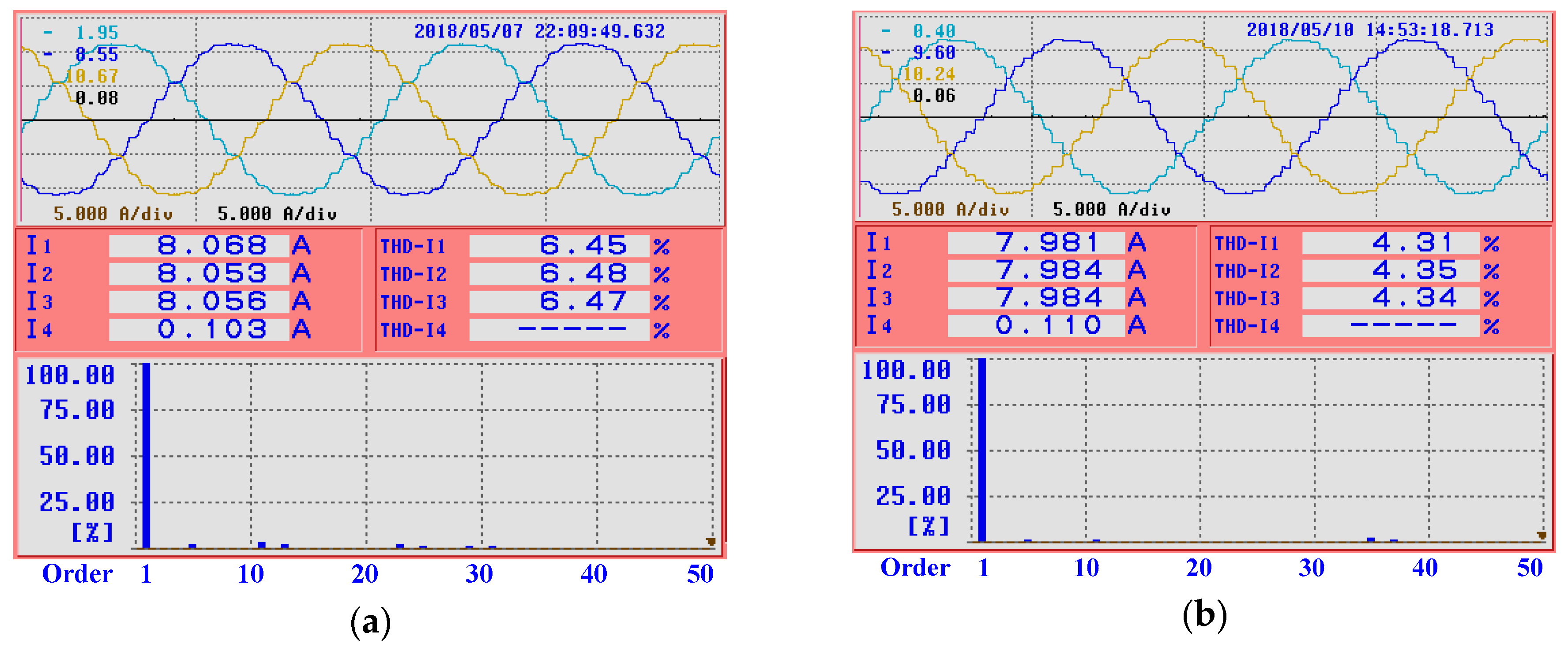
Figure 11.
Measured waveforms of the proposed rectifier. (a) Currents ip and iq of diodes Dp and Dq. (b) Currents im and in of diodes Dm and Dn, and output current if of SFR. (c) Output currents id1 and id2 of the two three-phase diode-bridge rectifier. (d) Input currents ia1 and ib1 of the three-phase diode-bridge rectifier I. (e) Output voltages ud1 and ud2 of the two three-phase diode-bridge rectifier. (f)Load voltage.
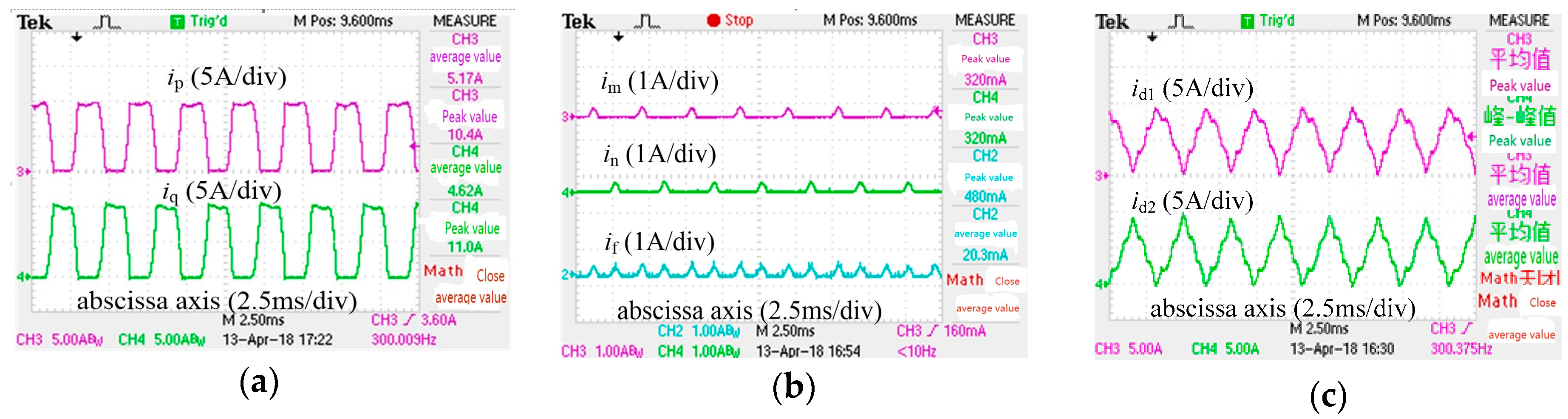

Figure 12.
Waveforms of input line currents. (a) Conventional 12-pulse rectifier. (b) 24-pulse rectifier with double-tapped IPR. (c) 24-pulse rectifier with unconventional IPR. (d) Proposed 36-pulse rectifier with unconventional IPR.
Figure 12.
Waveforms of input line currents. (a) Conventional 12-pulse rectifier. (b) 24-pulse rectifier with double-tapped IPR. (c) 24-pulse rectifier with unconventional IPR. (d) Proposed 36-pulse rectifier with unconventional IPR.

Table 1.
Rectifier specifications and components for experiments.
| Parameter | Value |
|---|---|
| Input phase voltage (rms) | 120 V |
| Line frequency | 50 Hz |
| Load filtering inductance | 10 mH |
| Primary tapped ratio (αm) of the unconventional IPR | 0.16 |
| Turn ratio (αn) of the unconventional IPR | 10.74 |
| Rated output power | 3 kW |
| Rated output current | 10 A |
Table 2.
Comparison of the Proposed Rectifier with Other MPRs.
| Topologies | Input line Current THD | IPR kVA Rating | Load Power | Efficiency |
|---|---|---|---|---|
| 12-pulse rectifier with conventional IPR | 12.23% | 2.04% UdId | 2932.1 W | 96% |
| 24-pulse rectifier with double-tapped IPR | 5.93% | 1.65% UdId | 2941.2 W | 96.3% |
| 24-pulse rectifier with unconventional IPR | 5.62% | 3.11% UdId | 2944.3 W | 96.4% |
| 36-pulse rectifier with unconventional IPR | 4.34% | 2.60% UdId | 2965.6 W | 97.1% |
© 2019 by the authors. Licensee MDPI, Basel, Switzerland. This article is an open access article distributed under the terms and conditions of the Creative Commons Attribution (CC BY) license (http://creativecommons.org/licenses/by/4.0/).
Share and Cite
MDPI and ACS Style
Lian, Y.; Yang, S.; Ben, H.; Yang, W. A 36-Pulse Diode Rectifier with an Unconventional Interphase Reactor. Energies 2019, 12, 820. https://doi.org/10.3390/en12050820
AMA Style
Lian Y, Yang S, Ben H, Yang W. A 36-Pulse Diode Rectifier with an Unconventional Interphase Reactor. Energies. 2019; 12(5):820. https://doi.org/10.3390/en12050820
Chicago/Turabian StyleLian, Yuxin, Shiyan Yang, Hongqi Ben, and Wei Yang. 2019. "A 36-Pulse Diode Rectifier with an Unconventional Interphase Reactor" Energies 12, no. 5: 820. https://doi.org/10.3390/en12050820
Note that from the first issue of 2016, this journal uses article numbers instead of page numbers. See further details here.