Article

A Novel Design of Static Electrostatic Generator for High Voltage Low Power Applications Based on Electric Field Manipulation by Area Geometric Difference

Department of Electrical Engineering, King Fahd University of Petroleum and Minerals (KFUPM), Dhahran 31261, Saudi Arabia
*
Author to whom correspondence should be addressed.
These authors contributed equally to this work.
Energies 2019, 12(5), 802; https://doi.org/10.3390/en12050802
Submission received: 18 January 2019 / Revised: 14 February 2019 / Accepted: 22 February 2019 / Published: 28 February 2019

Abstract

:
An electrostatic generator is an electromechanical device that produces static charges at high voltage and low current. This technology is mature enough, as it has existed for many centuries. Nevertheless, the working principle of most of the commonly used electrostatic generators is still based on typical mechanical methods, which consequently makes them bulky and limits their controllability on the generated charges, e.g., Van de Graaff generator that uses the friction between two different materials to generate electrostatic charges. In this paper, a novel design of a static electrostatic generator (SEG) is presented based on a completely different idea compared to existing electrostatic generators, which offers several potential benefits. The idea originates from the study of a parallel plates capacitor—for instance, if a voltage is applied to two plates of a capacitor, then according to Gauss’s law, both of the plates must have an equal and opposite charge. Suppose one of the plates has a different geometry, with a shorter length than the other, then the number of the charges on both plates will not be equal. Thus, by manipulating the geometrical area of the device, a different number of charges will be generated on both metal conductors. Therefore, a different number of charges are generated on both conductors; hence, by connecting both conductor plates of the capacitance, excess charges will remain on the device. The proposed idea was assessed with computer simulations using finite element and finite difference methods for a variety of different scenarios to determine the optimal design of the proposed device. The device offers several advantages over traditional electrostatic generators, such as that it can generate either positive or negative charges by merely reversing the polarity of the DC source; additionally, it is very simple, lightweight, and easy to manufacture. In particular, the principal advantage of the proposed device is that it is a static one, and no mechanical movement is required to produce charges. Further, the design is general enough and scalable. The simulation results demonstrate the performance of the proposed device.

1. Introduction

In the early 1900s, physics researchers needed a high-voltage DC source, in millions of volts, with low current to accelerate electrons and ions to investigate the internal atom construction. However, with the available equipment at that time, it meant installing a costly, huge, and well-insulated transformer and a high-voltage rectifier to provide high DC voltage for the particles accelerator [1]. In Reference [2], Van de Graff presented a simple and economical solution to produce a high DC voltage source with low current. Ever since the inception of an electrostatic generator and its impact on nuclear physics research, it has been gaining much attention in research.
In the renewable energy sector, electrostatic generation plays an important role as well. With the increasing energy demands worldwide and the effects to the earth ecosystem, such as global warming and pollution caused by traditional energy sources, such as oil, coal, and nuclear, the need for renewable energy sources increases. The increasing demands of renewable energy sources, capital cost reduction, and efficient renewable energy systems were some of the motivations that help to propel the world to investigate, research, and improve renewable energy to make it a more viable economic option. In Reference [3], Matthew presented a variable capacitor—which is an electrostatic generator—as a power source for space applications using electrets. More recent work done by O’Donnell, Schofield, Smith, and Cullen in Reference [4] on electrostatic power generation for wind turbine showed promising results for power grid generation. Since an offshore wind farm mostly uses High Voltage Direct Current (HVDC) to transmit power efficiently, the proposed generator eliminated the need for an AC to DC converter, since the electricity generated was DC. In a more recent technique from 2005 [5], Djairam, Hubacz, Morshuis, Marijnissen, Smit, in harvesting the wind energy, used an electrostatic wind converter (EWICON) instead of the traditional wind generator. EWICON generates the electrical power by forcing the charges to move in the opposite direction of the electric field by the wind to increase the energy of the system. In 2014 [6], the authors presented a high-efficiency ballistic electrostatic generator using microdroplets. The presented electrostatic generator has a conversion efficiency that reaches up to 48% in converting mechanical energy to electrical energy.
In energy harvesting, in 2011, de Queiroz and Domingues used an electrostatic generator known as a "doubler of electricity" as an energy harvesting device and a battery charger [7].
One of the major applications of electrostatic is bio-MEMS (biological microelectromechanical system). These electrostatic bio-MEMS actuators are designed for aqueous environments and benefit from the relativity permittivity factor of water, which is usually greater than 1. In Reference [8], The authors demonstrated a high-speed gap-closing actuator (GCA) with a low voltage level (6 V). The presented actuator was designed to generate up to 4.6mN force. In Reference [9], a curved electrode electrostatic actuator’s design, fabrication, and characterization were presented. The presented curved electrode actuator works with low voltage (±8 V) in an underwater environment, which resulted in large displacement and forces due to the high relative permittivity of water. In Reference [10], an actuator was fabricated without gold/chromium conductive layers to improve adhesion with minimal effect on the actuator displacement and force.
Electrostatic has a wide range of applications, such as precipitators, electrostatic air cleaning, inkjet printers, electrostatic painting, xerography, ion thrusters, and ion acceleration in nuclear research. In 2014, Wang, Yan, Hu, and Qian [11] investigated and tested the application of rotational speed measurement using electrostatic sensing. With a vast range of applications of an electrostatic generator, a highly efficient and more reliable electrostatic generator is required.
Whether in energy harvesting or renewable energy sources, the working principles of most of the electrostatic generators are based on mechanical force—either moving a belt, microdroplets or rotating capacitors plates—to move a medium, liquid or solid, which absorbed the charges to a higher potential. Thus, they have lower efficiency, they are bulky, and it is difficult to control the quantities of charges they produce. In this paper, the presented novel static electrostatic generator (SEG) can convert electrical energy with a low potential to a high potential. Consequently, the device can operate as a DC to DC voltage converter. Furthermore, the presented SEG can function as an electrostatic generator—similar to a Van de Graff generator—but unlike all other electrostatic generators, the device input and output energy is purely electrical energy. The proposed SEG can play a significant role in the renewable power sector as well. In fact, the proposed SEG can function as a high-voltage source, which is required by the electrostatic wind energy converter (EWICON) as in Reference [5]. For example, instead of connecting EWICON directly to a high-voltage source, it can be connected to a low-voltage source with SEG, which in turn can generate the high voltage required by the generator. Consequently, this will reduce the insulation required for the high voltage supply, which in turn reduces the cost.
A DC-to-DC converter is a type of electric power converter which converts a DC source voltage from one level to another. The DC-to-DC converter is one of an elemental circuit block in many electrical devices. It is an essential part of modern system development to maximize the energy harvest for a photovoltaic system and wind turbines. In the early days, before the development of power semiconductors, conversion of a DC voltage from one level to another was carried out through the conversion of a DC voltage to AC, then back again to DC. Consequently, these converters were relatively inefficient and expensive due to the uses of different electric components. The introduction of power semiconductors and integrated circuits made it economically viable to use different techniques to acquire the needed voltage level—for instance, one method which has been used to convert the DC power supply to high-frequency AC through the usage of semiconductors. Since the transformer voltage is a function in the frequency, then by feeding the generated high-frequency AC to a transformer, a high voltage level can be obtained. Since the obtained high voltage is an AC, a rectifier circuit is needed to convert the voltage back to DC.
Many electronic devices, such as cellular phones and laptop computers, which are powered by batteries, use DC to DC converters. These electronic devices often have several sub-circuits, each with its voltage level, which can be different from the voltage supplied by the battery or an external supply. As energy is drained from the battery, the voltage level starts declining. Therefore, DC to DC converters using high-frequency switching offer a method to increase voltage from a partially lowered battery voltage, thereby saving space instead of using multiple batteries to accomplish the same thing.
Walker and Sernia [12] showed the advantages of using many small DCAC converters over the usage of a single DCAC converter in residential photovoltaic (PV) applications. In Reference [13], the authors discussed the main disadvantage of the PV system, which is its variable voltage. They proposed a Matlab-based model for an intermediate DCDC converter which can increase the efficiency of the system by providing an impedance match between the PV system and load.
A comprehensive review was presented in Reference [14] to demonstrate various high-voltage gain DCDC converter topologies, control strategies, and recent trades. The paper covered and classified into several categories different numbers of topologies which have a high voltage conversion ratio, low cost, and high-efficiency performance. To optimize the output power of the photovoltaic system, it must operate at the maximum power point (MPP), as suggested in Reference [15]. The Maximum power point tracking (MPPT) algorithm allows the increase of the output power, and it commonly works with a DCDC converter. Additionally, the authors presented the analysis and the essential features of different topologies of DCDC converters which were designed and simulated for solar photovoltaic (PV) applications. Moreover, two conventional MPPT algorithms were evaluated by computer simulation to analyze their efficiency in different environmental conditions.
In Reference [16], Deihimi and Mahmoodieh reconfigured a high step-up DCDC converter and integrated it with conventional DCDC converters simultaneously with a battery. The proposed reconfiguration of a battery-integrated DCDC converter, BIC, with the linear quadratic regulator (LQR), was verified through simulations and experimental results. Das and Agarwal [17] presented a new high voltage gain and high-efficiency DCDC converter based on coupled inductors, an intermediate capacitor, and a leakage energy recovery scheme. It used the mutual coupling between conductors to store the energy in a magnetic field. The mutually coupled conductors are connected to capacitors of the output stage in a lossless manner. The high efficiency and high gain converter presented in Reference [17] has a high efficiency of 96% for low-output voltage sources.
A high-voltage gain DCDC converter for PV systems was presented in Reference [18]. The proposed converter can set up the voltage up to 311 V with the achievement of maximum power. The converter used coupled conductors and sets of capacitors and semiconductors. The converter is suitable for low-input voltages and low-power applications. In Reference [19], the authors presented a novel multiport high-voltage-gain DCDC converter with two boost stages at the input. The output voltage of the presented model can gain up to 20 times the input voltage. Lin and Dong [20] presented a novel soft-switching DCDC converter for renewable energy conversion systems with a solar PV cell or fuel cell stack as an input to achieve zero-voltage switching (ZVS), a turn-on for active switches and zero-current switching (ZCS), a turn-off for fast recovery diodes. The proposed converter achieved high step-up voltage conversion ratio using a boost converter and a voltage-doubler configuration with a coupled inductor.
A high-efficiency dual-mode resonant converter topology with a detailed theoretical analysis of the converter operation and its DC gain features was presented in Reference [21]—a converter which can maintain high efficiency for a wide input range at different output power levels by changing resonant modes depending on the panel operation conditions. The integration of two technologies, a switched capacitor and a switched coupled inductor, into one converter to increase voltage gain was presented in Reference [22]; the developed DCDC converter configuration has an efficiency of 93.6% at full load. Ardi, Ajami, and Sabahi [23] proposed a DCDC converter with high voltage gain, zero current switching of the main switch, and low-voltage stress of the main switches. Even though the presented converter shows a high voltage gain, it employed fewer components than a traditional converter.
A high-conversion-ratio bidirectional DCDC converter with maximum efficiency reaching up to 96.41% was presented in Reference [24], using a coupled inductor with a lower turn ratio and high conversion ratio. In Reference [25], Chen, Lu, Hung, and Liang used an interleaved boost converter to achieve a high step-up voltage conversion ratio with a maximum efficiency of 94.5%. A bidirectional DCDC converter using only two switches and an inductor–capacitor LC resonant transformer capable of controlling the power flow with a high efficiency of 92% was shown in Reference [26], while in Reference [27], a converter using the techniques of a switched-capacitor, coupled-inductor, and multiplier capacitor to achieve high voltage gain was presented. In Reference [28], multilevel DCDC converters were presented for interconnecting medium-voltage DC networks. In Reference [29], Ahrabi, Ardi, Elmi, and Ajami presented a multi-input DCDC converter with a control method for hybrid electric vehicles to enhance the efficiency and performance of the converter, while in Reference [30], a multi-input DCDC converter was presented as a solution for galvanic isolation for ACDC using an isolation transformer. In Reference [31], a compact and lightweight design of onboard electric vehicle (EV) charger which uses a bidirectional ACDC single-stage converter was presented.
In this paper, the proposed electrostatic generator (SEG) is small, lightweight, easy to manufacture, and scalable. SEG can be resized to generate electrostatic charges more efficiently with different voltage levels. Additionally, SEG is more reliable, since it does not depend on any mechanical movement to generate static charges. Moreover, SEG can produce charges in controllable quantities. The proposed SEG can work as an electrostatic generator, such as the Van de Graaff generator, with efficiency reaching up to 46.95%. The efficiency of the presented SEG is considered among the highest in electrostatic generation. Further, SEG does not require any gas or liquid to be under high pressure to generate charges with high efficiency. Unfortunately, using the device in a DCDC converter with an efficiency of 46.95% is not preferable, even though the device did not require any inductor, which means it is not temperature-sensitive, nor did it use many capacitors to achieve the same high voltage level required by different applications.
The remainder of the paper is organized as follows. Section 2 discusses the working principle of SEG which will show a different perspective on how static charges can be generated, which may help in understanding some of the phenomena associated with the static charges generations. Section 3 presents the proposed methodology. Results and Discussions are presented in Section 4, and Section 5 concludes the paper.

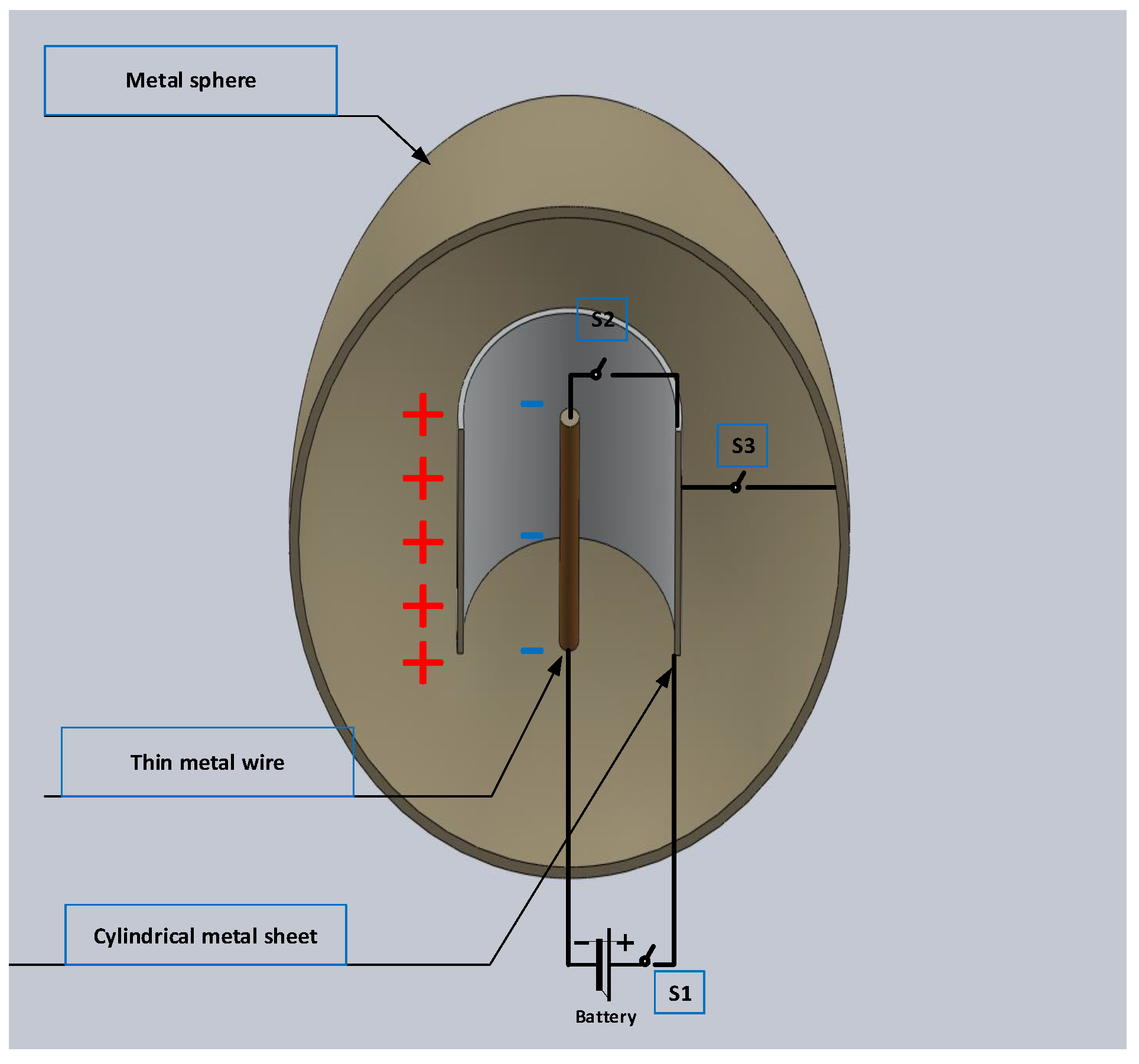
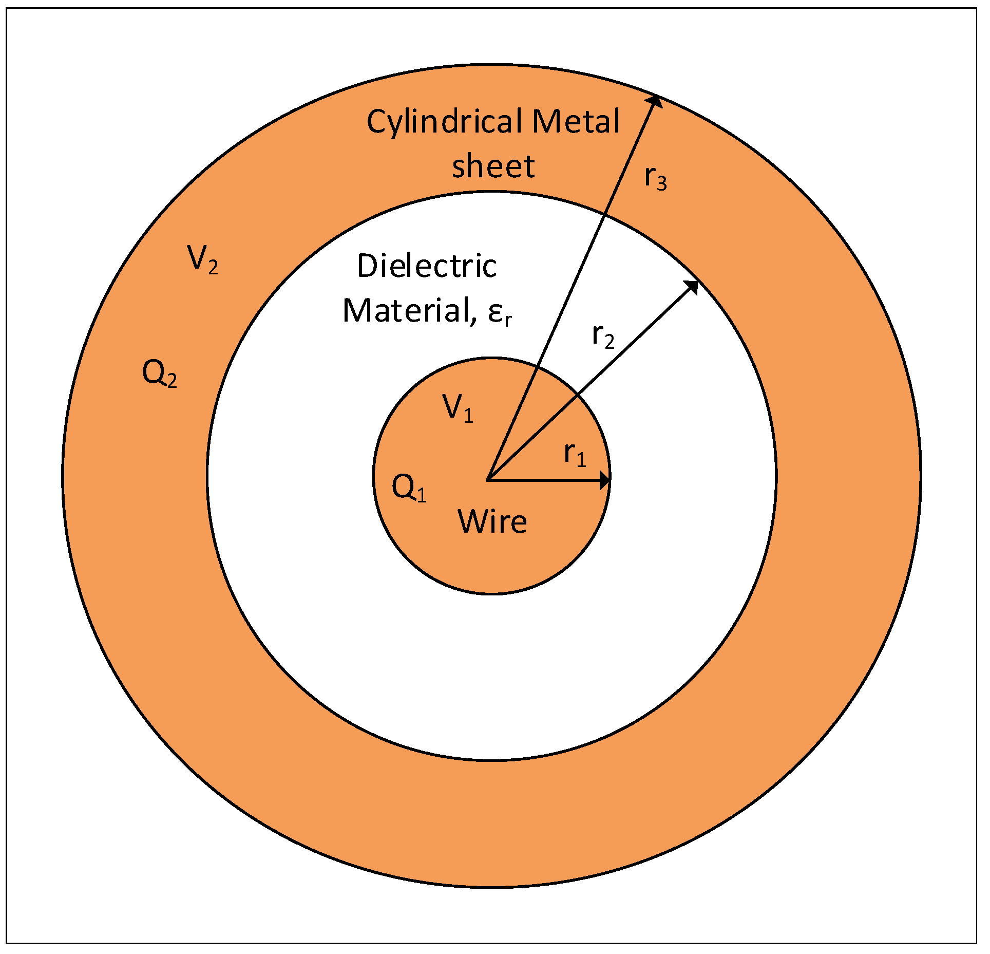
2. Proposed Device Working Principle

Figure 1 shows the basic construction of the proposed device, which is similar to a coaxial cable, with a thin wire, a metal sheet surrounding the thin wire, and a dielectric material between them. Three assumptions should be made at the beginning: (1) There should not be any charges on any of the conductors; (2) the dielectric material, initially, should have no dipoles, and; (3) the applied voltage should be DC Voltage. These assumptions are necessary to ease understanding but will not affect the outcomes.
When the cylindrical metal sheet is connected to a positive voltage source and the metal wire is connected to a negative voltage source, the charges start to accumulate on the surfaces of the conductors. Since the area of the thin metal wire is significantly smaller than the area of the cylindrical metal sheet, more charges will accumulate on the cylindrical metal sheet. After charging both conductors with different amount of charges due to surface area geometric difference between them, switch S1 is opened and switch S2 is closed, see Figure 2. By closing S2, the same number of charges on the thin wire will cancel the same number of charges on the cylindrical metal sheet. Since the electric field which was binding the remaining extra charges on the cylindrical metal sheet is gone when S2 is connected, the remaining charges on the cylindrical metal sheet are set free. Thus, the number of free charges can be calculated by:
Q F r e e = Q C y l i n d e r i c a l M e t a l S h e e t Q W i r e .
The free charges cannot move to the thin wire, since the static charges are not allowed to be inside a metal. The metal sphere shown in Figure 2 acts as a charge collector, since no static charges are allowed to be inside a conductor. The charges start to accumulate once switches S2 and S3 are closed while S1 is opened. The metal sphere prevents any voltage difference across S1 except for the battery voltage. Any enclosed metal surface will be sufficient to act as a charge accumulator surface, whether spherical or cylindrical.
To estimate the device efficiency, firstly, the total energy stored (TES) within the device after it is fully charged must be calculated. Then, by forcing the number of charges on the cylindrical metal sheet to equal the number of charges on the thin wire, the energy lost (EL) can be calculated. Thus, the efficiency can be calculated by:
η = T E S E L T E S × 100
The novel SEG presented in this paper has many advantages over existing ones. It is capable of fast charge generation using fast switching transistors. Additionally, it can generate either positive or negative charges by merely reversing the battery polarity. Moreover, it can control the number of charges generated by controlling the voltage and the switching time of the transistors. Furthermore, it does not require any mechanical method to generate electrostatic charges, as it is a static device. The efficiency of the presented device cannot reach a higher level than 46.95%, as will be shown in the Results section, where many different scenarios were tested to optimize the device output and efficiency. The simulation of the device was carried out in MATLAB (R2017a, MathWorks, Inc, Natick, MA, USA)using the finite difference method (FDM), and FEMM ( version 4.2, David Meeker, QinetiQ North America, MA, USA) [32] using the finite element method (FEM) to ensure the obtained results are in a good agreement.

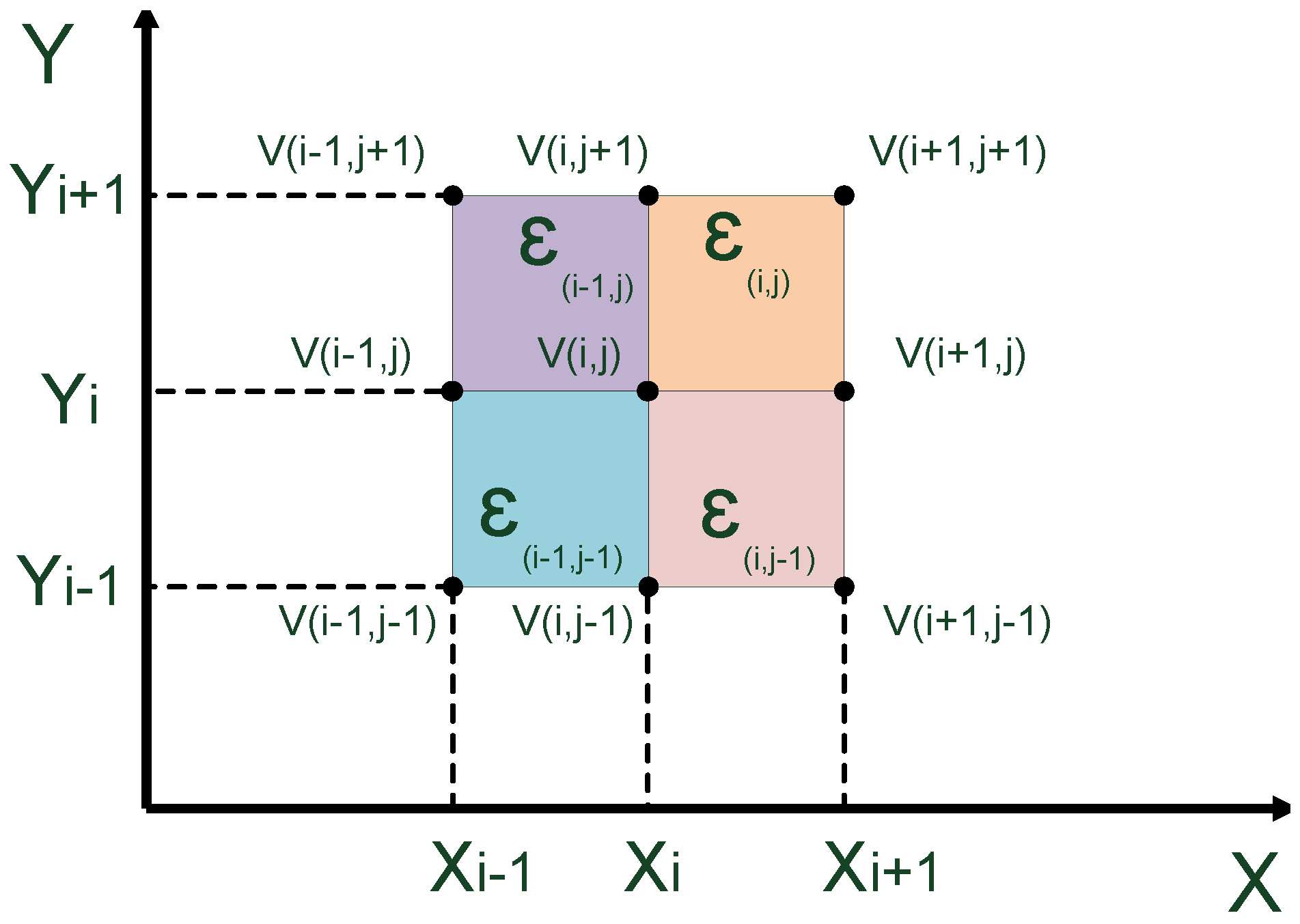
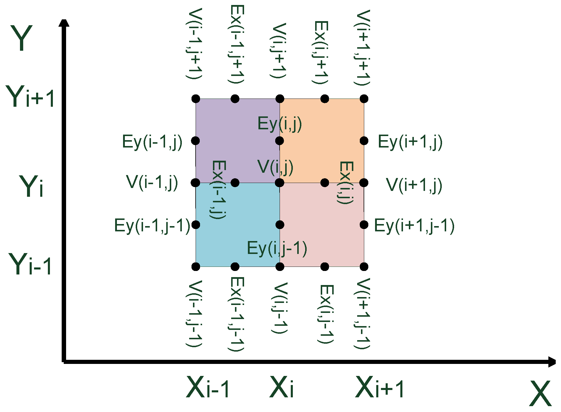
3. Finite Difference Method

One of the numerical solutions used in simulating the proposed device was FDM. FDM is one of the numerical solution methods to solve complex problems that are difficult to solve analytically or by linearizing differential equations [33]. It is a numerical approximation solution that converts differential equations to finite-difference equations, and through iterations of algebraic equations, a solution of a complex differential equation can be obtained [34].
Laplace’s equation and Poisson’s equation are powerful tools to represent an electrostatic system. Solving these differential equations for complex geometry in order to represent the behavior of the electrostatic model must be carried out through a numerical solution. There are many methods of finite difference that can be applied to solve Laplace’s and Poisson’s equations; the method used in this paper of finite difference is the five-point star (leapfrog) [35].

3.1. Laplace’s Equation

To solve the differential equation of the proposed device, we must convert the differential equation to a finite difference equation:
· D ^ = 0 ,
since:
D ^ = ε 0 ε r E ^ ,
then:
· ε 0 ε r E ^ = 0 ,
2 V = 0 ,
since:
2 = 2 x 2 + 2 y 2 + 2 z 2 .
Under the assumption that there are no changes in the z-components, we only solve for x and y, thus:
2 V = 2 V x 2 + 2 V y 2 .
To solve the Laplace differential equation, firstly, the area of interest to study and simulate the behavior of electrostatic must be divided into a fine mesh using the five-point star configuration as shown in Figure 3.
2 V x 2 V ( i + 1 , j ) 2 V ( i , j ) + V ( i 1 , j ) h 2
2 V y 2 V ( i , j + 1 ) 2 V ( i , j ) + V ( i , j 1 ) h 2
Uniform grid case:
2 V = V ( i + 1 , j ) + V ( i 1 , j ) + V ( i , j + 1 ) + V ( i , j 1 ) 4 V ( i , j ) h 2 = 0
V ( i , j ) = 1 4 V ( i + 1 , j ) + V ( i 1 , j ) + V ( i , j + 1 ) + V ( i , j 1 )
Varying dielectrics case:
a 0 = ϵ ( i , j ) + ϵ ( i 1 , j ) + ϵ ( i , j 1 ) + ϵ ( i 1 , j 1 )
a 1 = 1 2 ϵ ( i , j ) + ϵ ( i , j 1 )
a 2 = 1 2 ϵ ( i 1 , j ) + ϵ ( i , j )
a 3 = 1 2 ϵ ( i 1 , j 1 ) + ϵ ( i 1 , j )
a 4 = 1 2 ϵ ( i , j 1 ) + ϵ ( i 1 , j 1 )
a 0 V ( i , j ) + a 1 V ( i + 1 , j ) + a 2 V ( i , j 1 ) + a 3 V ( i 1 , j ) + a 4 V ( i , j + 1 ) = 0
V ( i , j ) = 1 a 0 [ a 1 V ( i + 1 , j ) + a 2 V ( i , j 1 ) + a 3 V ( i 1 , j ) + a 4 V ( i , j + 1 ) ]

3.2. Poisson’s Equation

Using Poisson’s equation, the charges on each plate can be calculated. Since:
· D = ρ c
a 0 V ( i , j ) + a 1 V ( i + 1 , j ) + a 2 V ( i , j 1 ) + a 3 V ( i 1 , j ) + a 4 V ( i , j + 1 ) = Q ( i , j ) ϵ 0

3.3. Electric Field

The electric field is calculated as shown in Figure 4.
E = V
E = x ^ V x y ^ V x
E = E x ( i , j ) + E y ( i , j )
E x ( i , j ) = V ( i + 1 , j ) V ( i , j ) h
E y ( i , j ) = V ( i , j + 1 ) V ( i , j ) h
After obtaining the potential for each point on the unified mesh, the electric field can be calculated using a gradient function in MATLAB. The magnitude of the net electric field can be calculated as:
E = E x 2 + E y 2 .
After obtaining the electric field of the unified mesh, the energy for each cell in the mesh can be calculated using:
E n e r g y = 1 2 ϵ 0 E 2 V c e l l .

4. Simulation Results

The simulation of the device was carried out in MATLAB using FDM and FEMM software [32] using FEM. The proposed device and its dimensions are shown in Figure 5 and Table 1. The proposed dimensions are based on the applied DC voltage and the breakdown voltage of the dielectric material between the thin wire and the metal sheet. The applied DC voltage must as high as possible and below the breakdown voltage of the dielectric material between the thin wire and the metal sheet. Different scenarios were studied to find the optimum design, maximum output charges, and maximum efficiency.
To determine the number of charges freed from the outer metal sheet, first, a voltage must be applied between the wire and the metal sheet (see Table 2, Case 0). Then, the difference in the number of charges between the wire and the metal sheet, which is due to the area geometric difference between both of the conductors, is the number of free charges. Figure 6 shows the electric potential distribution of the proposed device. Figure 7 shows the electric field distribution of the proposed device.
To estimate the efficiency of the proposed device, first, an equal amount of the charges are forced on both the wire and the metallic sheet, which is the number of charges on the thin wire since those charges will be canceled out with an equal number of charges on the metallic sheet. Then, by comparing the total amount of energy stored within the device with the amount of energy associated with an equal number of charges, the efficiency of the device can be calculated. Thus, by forcing:
Q 2 = Q 1 ,
and by calculating the energy associated with the charges, efficiency can be calculated.

4.1. CASE I: Effects of the Dielectric Material

In this case, the dielectric material between the conductors is replaced with a material which has ϵ r = 10, to study the effects on charge production and the efficiency of the device, see Table 2, Case I. Figure 8 shows the electric potential distribution of the proposed device. Figure 9 shows the electric field distribution of the proposed device.
Table 2, Case I shows that the number of freed charges is slightly lower, and the efficiency of the device is dropped dramatically. This is due to the loss of the energy stored within the dielectric material.

4.2. CASE II: Effects of the Applied Voltage

In this case, the applied voltage between the conductors is reduced by half of the original value (500V) to study the effects on charge production and the efficiency of the device, see Table 2, Case II. Figure 10 shows the electric potential distribution of the proposed device. Figure 11 shows the electric field distribution of the proposed device.
Table 2, Case II shows that the number of freed charges and the efficiency dropped about half the values of Case 0, see Table 2. Thus, increasing the potential will help in improving both the efficiency of the device and the number of generated charges. The breakdown voltage and the maximum switching voltage must be considered in the design.

4.3. CASE III: Effects of the Thin Wire Diameter

In this case, the diameter of the thin wire is doubled to study the effects on charge production and the efficiency of the device, see Table 2, Case III. Figure 12 shows the electric potential distribution of the proposed device. Figure 13 shows the electric field distribution of the proposed device.
Table 2, Case III shows that the number of freed charges is slightly higher due to the slight decrements of distance between the conductors, while the efficiency of the device is dropped dramatically.

4.4. CASE IV: Effects of the Thin Metal Sheet Diameter

In this case, the diameters of the thin metal sheet are doubled to study the effects on charge production and the efficiency of the device, see Table 2, Case IV. Figure 14 shows the electric potential distribution of the proposed device. Figure 15 shows the electric field distribution of the proposed device.
Table 2, Case IV shows that the number of freed charges increases due to the increase in the surface area of the thin metal sheet, while the efficiency of the device is slightly decreased.

4.5. CASE V: Effects of the Thin Metal Sheet Thickness

In this case, the thickness of the thin metal sheet is doubled to study the effects on charge production and the efficiency of the device, see Table 2, Case V. Figure 16 shows the electric potential distribution of the proposed device. Figure 17 shows the electric field distribution of the proposed device.
Table 2, Case V shows that the number of freed charges is slightly lower than in Case 0; this is because the number of charges on the thin wire is slightly higher, while the charges on the metal sheet are slightly lower. This will lead to lower freed charges and lower efficiency. The higher the thickness of the metal shell, the more charges are allowed to be on the metal, which will lead to higher energy stored within the device.
From the previous results, the optimum design of the proposed device must have a higher metal sheet area for the outer conductor, while the area of the thin metal wire must be as small as possible. In addition, the applied voltage must be as large as possible, taking the breakdown voltage and the maximum withstand voltage of the transistors into account. Furthermore, the thickness of the metal sheet must be as small as possible, so fewer charges are allowed to be on the thin metal sheet and lower energy is stored within the device.

5. Conclusions

In this paper, a novel design of a static electrostatic generator was presented with an overall efficiency reaching up to 46.95%, especially in cases of ideal switching transistors. The device consists of thin wire and a thin metallic sheet and is enclosed by a metal to act as a charge-collector. The free charges are delivered to the enclosed metal surface in a chunk, which is actually a set of charges with each operation. The amplitude of the DC voltage and the geometric design of the device can control the number of freed charges. Thus, if a set of desired charges is required to be deposited on the enclosed metal, these charges must be a multiplication of each chunk generated. Therefore, the proposed device gives a certain degree of control over how many charges can be enclosed on metal surface. Further, the proposed device can generate negative or positive charges by simply reversing the polarity of the DC voltage source. The device is tested intensively using simulations based on standard finite element and finite difference methods for a variety of scenarios to obtain the highest efficiency and also to determine key parameters affecting the device efficiency. It was concluded that the efficiency of the proposed device is heavily dependent on the applied voltage and the geometric design, and the claimed efficiency might not be the highest as presented in literature, but it is rather a relatively simple design, static, controllable, lightweight, small, and it does not require any mechanical moving parts, which is a huge advantage over many other electrostatic generators.

Author Contributions

The authors’s contributions are given as follows: “conceptualization, H.A. and M.K.; methodology, H.A.; software, H.A.; validation, H.A., M.K., and M.A.; formal analysis, H.A., M.K. and M.A.; investigation, H.A., M.K. and M.A.; resources, M.K.; data curation, H.A.; writing—original draft preparation, H.A., M.K. and M.A.; writing—review and editing, H.A. and M.K.; visualization, H.A., M.K. and M.A.; supervision, M.K. and M.A.; project administration, H.A. and M.K.; funding acquisition, M.K.”.

Funding

The authors would like to acknowledge the support provided by the Deanship of Research (DSR) at King Fahd University of Petroleum and Minerals (KFUPM) for funding this work through Project No. RG171009.

Conflicts of Interest

The authors declare no conflict of interest.

Abbreviations

The following abbreviations are used in this manuscript:
WEnergy [J]
wEnergy density [ J m 3 ]
DElectric filed density [ C m ]
EElectric filed [ V m ]
ε r Relative permittivity
ε 0 Permittivity of Vacuum [ F m ]
VVoltage [V]
ρ c Charge density [ C m 2 ]
eelectron charge [C]
QTotal charge [C]
V c e l l Volume of cubic cell [ m 3 ]
D C Direct current
A C Alternating current
S E G Static electrostatic generator
E W I C O N Electrostatic wind converter
M P P Maximum power point
M P P T Maximum power point tracking
P V Solar photovoltaic
D C D C DC to DC converter
L Q R Linear quadratic regulator
Z V S Zero-voltage switches
Z C S Zero-current switches
E V electric vehicles
S 1 , S 2 , S 3 Switches
T E S Total energy stored
E L Energy lost
F D M Finite difference method
F E M Finite element method
η Efficiency

References

  1. Fortescue, R.L.; Hall, P.D. The High-Voltage Electrostatic Generator at the Atomic Energy Research Establishment. Proc. IEE—Part I Gen. 1949, 96, 77–85. [Google Scholar] [CrossRef]
  2. van de Graaff, R.J.; Compton, K.T.; van Atta, L.C. The Electrostatic Production of High Voltage for Nuclear Investigations. Phys. Rev. 1933, 43, 149–157. [Google Scholar] [CrossRef]
  3. Matthew, R.E. The use of electrets in electrostatic generators for space. Electr. Eng. 1962, 81, 850–854. [Google Scholar] [CrossRef]
  4. O’Donnell, R.; Schofield, N.; Smith, A.C.; Cullen, J. Design Concepts for High-Voltage Variable-Capacitance DC Generators. IEEE Trans. Ind. Appl. 2009, 45, 1778–1784. [Google Scholar] [CrossRef]
  5. Djairam, D.; Morshuis, P.H.F.; Smit, J.J. A novel method of wind energy generation-the electrostatic wind energy converter. IEEE Electr. Insul. Mag. 2014, 30, 8–20. [Google Scholar] [CrossRef]
  6. Xie, Y.; Bos, D.; de Vreede, L.J.; de Boer, H.L.; van der Meulen, M.J.; Versluis, M.; Sprenkels, A.J.; van den Berg, A.; Eijkel, J.C.T. High-efficiency ballistic electrostatic generator using microdroplets. Nat. Commun. 2014, 5, 3575. [Google Scholar] [CrossRef] [PubMed] [Green Version]
  7. de Queiroz, A.C.M.; Domingues, M. The Doubler of Electricity Used as Battery Charger. IEEE Trans. Transp. Electrif. 2011, 58, 797–801. [Google Scholar] [CrossRef]
  8. Shih, R.M.; Contreras, D.S.; Massey, T.L.; Greenspun, J.T.; Pister, K.S.J. Characterization of electrostatic gap-closing actuator arrays in aqueous conditions. In Proceedings of the 2018 IEEE Micro Electro Mechanical Systems (MEMS), Belfast, UK, 21–25 January 2018; pp. 596–599. [Google Scholar] [CrossRef]
  9. Preetham, B.S.; Lake, M.A.; Hoelzle, D.J. A curved electrode electrostatic actuator designed for large displacement and force in an underwater environment. J. Micromech. Microeng. 2017, 27, 095009. [Google Scholar] [CrossRef]
  10. Burugupally, S.P.; Mangels, J.A. Performance evaluation of a curved electrode actuator fabricated without gold/chromium conductive layers. Microsyst. Technol. 2018, 24, 3479–3485. [Google Scholar] [CrossRef]
  11. Wang, L.; Yan, Y.; Hu, Y.; Qian, X. Rotational Speed Measurement Through Electrostatic Sensing and Correlation Signal Processing. IEEE Trans. Instrum. Meas. 2014, 63, 1190–1199. [Google Scholar] [CrossRef]
  12. Walker, G.R.; Sernia, P.C. Cascaded DC-DC converter connection of photovoltaic modules. IEEE Trans. Power Electron. 2004, 19, 1130–1139. [Google Scholar] [CrossRef]
  13. Marodkar, M.; Adhau, S.; Sabley, M.; Adhau, P. Design and simulation of DC-DC converters for Photovoltaic system based on MATLAB. In Proceedings of the 2015 International Conference on Industrial Instrumentation and Control (ICIC), Pune, India, 28–30 May 2015; pp. 1478–1483. [Google Scholar] [CrossRef]
  14. Savakhande, V.B.; Bhattar, C.L.; Bhattar, P.L. Voltage-lift DC-DC converters for photovoltaic application-a review. In Proceedings of the 2017 International Conference on Data Management, Analytics and Innovation (ICDMAI), Pune, India, 24–26 February 2017; pp. 172–176. [Google Scholar] [CrossRef]
  15. Soriano, L.A.; Ponce, P.; Molina, A. Analysis of DC-DC converters for photovoltaic applications based on conventional MPPT algorithms. In Proceedings of the 2017 14th International Conference on Electrical Engineering, Computing Science and Automatic Control (CCE), Mexico City, Mexico, 20–22 October 2017; pp. 1–6. [Google Scholar] [CrossRef]
  16. Deihimi, A.; Mahmoodieh, M.E.S. Analysis and control of battery-integrated dc/dc converters for renewable energy applications. IET Power Electron. 2017, 10, 1819–1831. [Google Scholar] [CrossRef]
  17. Das, M.; Agarwal, V. Design and Analysis of a High-Efficiency DC DC Converter With Soft Switching Capability for Renewable Energy Applications Requiring High Voltage Gain. IEEE Trans. Ind. Electron. 2016, 63, 2936–2944. [Google Scholar] [CrossRef]
  18. Freitas, A.A.A.; Tofoli, F.L.; Júnior, E.M.S.; Daher, S.; Antunes, F.L.M. High-voltage gain DC–DC boost converter with coupled inductors for photovoltaic systems. IET Power Electron. 2015, 8, 1885–1892. [Google Scholar] [CrossRef]
  19. Prabhala, V.A.K.; Fajri, P.; Gouribhatla, V.S.P.; Baddipadiga, B.P.; Ferdowsi, M. A DC DC Converter With High Voltage Gain and Two Input Boost Stages. IEEE Trans. Power Electron. 2016, 31, 4206–4215. [Google Scholar] [CrossRef]
  20. Lin, B.R.; Dong, J.Y. New zero-voltage switching DC-DC converter for renewable energy conversion systems. IET Power Electron. 2012, 5, 393–400. [Google Scholar] [CrossRef]
  21. Liang, Z.; Guo, R.; Li, J.; Huang, A.Q. A High-Efficiency PV Module-Integrated DC/DC Converter for PV Energy Harvest in FREEDM Systems. IEEE Trans. Power Electron. 2011, 26, 897–909. [Google Scholar] [CrossRef]
  22. Chen, S.M.; Lao, M.L.; Hsieh, Y.H.; Liang, T.J.; Chen, K.H. A Novel Switched-Coupled-Inductor DC DC Step-Up Converter and Its Derivatives. IEEE Trans. Ind. Appl. 2015, 51, 309–314. [Google Scholar] [CrossRef]
  23. Ardi, H.; Ajami, A.; Sabahi, M. A Novel High Step-Up DC–DC Converter With Continuous Input Current Integrating Coupled Inductor for Renewable Energy Applications. IEEE Trans. Ind. Electron. 2018, 65, 1306–1315. [Google Scholar] [CrossRef]
  24. Liu, H.; Wang, L.; Ji, Y.; Li, F. A Novel Reversal Coupled Inductor High-Conversion-Ratio Bidirectional DC DC Converter. IEEE Trans. Power Electron. 2018, 33, 4968–4979. [Google Scholar] [CrossRef]
  25. Chen, Y.T.; Lu, Z.X.; Liang, R.H.; Hung, C.W. Analysis and implementation of a novel high step-up DC DC converter with low switch voltage stress and reduced diode voltage stress. IET Power Electron. 2016, 9, 2003–2012. [Google Scholar] [CrossRef]
  26. Ishigaki, M.; Shin, J.; Dede, E.M. A Novel Soft Switching Bidirectional DC DC Converter Using Magnetic and Capacitive Hybrid Power Transfer. IEEE Trans. Power Electron. 2017, 32, 6961–6970. [Google Scholar] [CrossRef]
  27. Chen, Y.T.; Lu, Z.X.; Liang, R.H. Analysis and Design of a Novel High-Step-Up DC DC Converter With Coupled Inductors. IEEE Trans. Power Electron. 2018, 33, 425–436. [Google Scholar] [CrossRef]
  28. Du, S.; Wu, B.; Tian, K.; Xu, D.; Zargari, N.R. A Novel Medium-Voltage Modular Multilevel DC DC Converter. IEEE Trans. Ind. Electron. 2016, 63, 7939–7949. [Google Scholar] [CrossRef]
  29. Ahrabi, R.R.; Ardi, H.; Elmi, M.; Ajami, A. A Novel Step-Up Multiinput DC DC Converter for Hybrid Electric Vehicles Application. IEEE Trans. Power Electron. 2017, 32, 3549–3561. [Google Scholar] [CrossRef]
  30. Jou, H.L.; Huang, J.J.; Wu, J.C.; Wu, K.D. Novel Isolated Multilevel DC DC Power Converter. IEEE Trans. Power Electron. 2016, 31, 2690–2694. [Google Scholar] [CrossRef]
  31. Prasanna, U.R.; Singh, A.K.; Rajashekara, K. Novel Bidirectional Single-phase Single-Stage Isolated AC DC Converter With PFC for Charging of Electric Vehicles. IEEE Trans. Transp. Electrif. 2017, 3, 536–544. [Google Scholar] [CrossRef]
  32. Meeker, D.C. Finite Element Method Magnetics, Version 4.2. Finite Element Method Magnetics. Available online: http://www.femm.info/wiki/HomePage (accessed on 27 February 2019).
  33. Sadiku, M.N. Numerical Techniques in Electromagnetics with MATLAB; CRC Press: Boca Raton, FL, USA, 2009. [Google Scholar]
  34. Kraus, J.D. Electromagnetics; McGraw-Hill Companies: New York, NY, USA, 1992. [Google Scholar]
  35. Nagel, J.R. Numerical Solutions to Poisson Equations Using the Finite-Difference Method [Education Column]. IEEE Antennas Propag. Mag. 2014, 56, 209–224. [Google Scholar] [CrossRef]
Figure 1. Internal construction of the proposed static electrostatic generator (SEG).
Energies 12 00802 g001
Figure 2. Field interaction of the proposed SEG.
Energies 12 00802 g002
Figure 3. The potential interaction of the proposed SEG.
Energies 12 00802 g003
Figure 4. The electric field interaction of the proposed SEG.
Energies 12 00802 g004
Figure 5. Cross-section of the inner and outer conductors of the proposed device.
Energies 12 00802 g005
Figure 6. The electric potential distribution of the proposed device.
Energies 12 00802 g006
Figure 7. The electric field distribution of the proposed device.
Energies 12 00802 g007
Figure 8. The electric potential distribution of the proposed device when ϵ r = 10.
Energies 12 00802 g008
Figure 9. Tlectric field distribution of the proposed device when ϵ r = 10.
Energies 12 00802 g009
Figure 10. The electric potential distribution of the proposed device when the voltage is halved.
Energies 12 00802 g010
Figure 11. The electric field distribution of the proposed device when the voltage is halved.
Energies 12 00802 g011
Figure 12. The electric potential distribution of the proposed device when the diameter of the thin wire is doubled.
Energies 12 00802 g012
Figure 13. The electric field distribution of the proposed device when the diameter of the thin wire is doubled.
Energies 12 00802 g013
Figure 14. The electric potential distribution of the proposed device when the thin metal sheet diameter is doubled.
Energies 12 00802 g014
Figure 15. The electric field distribution of the proposed device when the thin metal sheet diameter is doubled.
Energies 12 00802 g015
Figure 16. The electric potential distribution of the proposed device when the thickness of metal sheet is doubled.
Energies 12 00802 g016
Figure 17. The electric field distribution of the proposed device when the thickness of metal sheet is doubled.
Energies 12 00802 g017
Table 1. System parameters.
Dimension of the Simulated Volume
X (mm)Y (mm)Z (mm)
2020100
Device Parameters
r 1 (mm) r 2 (mm) r 3 (mm) ϵ r V DC (Volt)
0.0411.111000
Table 2. The device performance comparisons.
Case 0Case ICase IICase IIICase IVCase V
V 1 (Volt)500500250500500500
V 2 (Volt)−500−500−250−500−500−500
ϵ r 1101111
r 1 (μm)404040804040
r 2 (mm)111121
r 3 (mm)1.11.11.11.12.11.2
Q 1 (Coulombs)1.74644 × 10 9 1.73631 × 10 8 8.7322 × 10 10 2.19035 × 10 9 1.3409 × 10 9 1.77257 × 10 9
Q 2 (Coulombs)−3.22398 × 10 9 −1.88247 × 10 8 −1.61199 × 10 9 −3.66845 × 10 9 −3.4159 × 10 9 −3.13439 × 10 9
Q f r e e (Coulombs)−1.47754 × 10 9 −1.4616 × 10 9 −7.3877 × 10 10 −1.4781 × 10 9 −2.075 × 10 9 −1.36182 × 10 9
Energy Stored (J)1.17827 × 10 6 9.03654 × 10 6 2.94569 × 10 7 1.41549 × 10 6 1.14532 × 10 6 1.19127 × 10 6
When Q 1 = − Q 2
Energy Stored (J)6.25078 × 10 7 8.63198 × 10 6 2.18325 × 10 7 1.0802 × 10 6 6.2438 × 10 7 8.98687× 10 7
Efficiency46.950%4.48%25.88%23.69%45.48%24.56%

