Article

A Thermo-Hydro-Mechanical-Chemical Coupling Model and Its Application in Acid Fracturing Enhanced Coalbed Methane Recovery Simulation

1
College of Mining, Liaoning Technical University, Fuxin 123000, China
2
Center of Technology, Shanxi Lu’an Mining (Group) Limited Liability Company, Changzhi 046299, China
3
State Key Laboratory Cultivation Base for Gas Geology and Gas Control, Henan Polytechnic University, Jiaozuo 454003, China
*
Authors to whom correspondence should be addressed.
Energies 2019, 12(4), 626; https://doi.org/10.3390/en12040626
Submission received: 9 January 2019 / Revised: 10 February 2019 / Accepted: 14 February 2019 / Published: 15 February 2019

Abstract

:
The reservoir permeability dominates the transport of gas and water in coal seam. However, coal seams rich in gas usually contain various pores and fractures blocked by a large amount of minerals, which leads to an ultra-low permeability and gas extraction rate, and thus an increase of drilling workload. We first propose a thermo-hydro-mechanical-chemical coupled model (THMC) for the acid fracturing enhanced coalbed methane recovery (AF-ECBM). Then, this model is applied to simulate the variation of key parameters during AF-ECBM using a 2D geometry. The effect of different extraction schedules are comparatively analyzed to give an insight into these complex coupling responses in coal seam. Result confirms that the AF-ECBM is an effective way to increase the reservoir permeability and improve the gas production using the proposed model. The range of permeability increment zone increases most dramatically in the way of acid fracturing, followed by none-acid fracturing and acidizing over time. The gas production in order is: acid fracturing (AF-ECBM) > fracturing (F-ECBM) > acidification (A-ECBM)> direct extraction (D-CBM).

1. Introduction

Coalbed methane, an unconventional source of clean energy, also poses a risk of disasters (gas explosions, outbursts) to coal mining workers [1,2]. The pores and fractures within coal seams are the storage and migration places for methane. The pore structure is the main transport pathway for gas and formation water during coalbed methane recovery. Therefore, the permeability of coal reservoirs is the key parameter that dominates gas and water migration [3]. Most coal reservoirs in China are characterized by low permeability (~0.001‒~0.1 mD), which has largely restricted coal seam degassing processes, especially when the mining moves towards deeper depths [4,5,6,7]. In order to guarantee safe mining and CBM production, the reservoir permeability should be further improved to increase the efficiency of coalbed methane extraction.
Several methods for increasing the permeability have been put forward [8,9,10], including physical methods such as hydraulic fracturing, water slotting, explosions within deep holes, and chemical methods. Hydraulic fracturing is considered a primary and commonly used technology among the physical methods. It is proved that by injecting water, fracturing liquid and proppant into coal reservoir to cause fresh fractures and open the preexisted fractures hydraulic fracturing can improve the permeability [11,12,13]. Also, foreign gases can be injected into coal seams to prompt gas transport from the reservoir to the production well, a process known as CO2/N2- ECBM recovery [14]. Due to the greater competitive adsorption capacity of CO2, CH4 is replaced by injected CO2 on the pore surfaces. By this means, CH4 production is enhanced and also CO2 is stored in coal seam, and a good economic and environmental benefit can be achieved [10,15,16,17,18,19]. The wave shock and heating methods are also applied to increase reservoir permeability, however they are limited because of the range of the damage zone induced by shock and heating is restricted. More efforts should be done on these methods [20]. Injection of acid solutions into coal seam to dissolve the minerals contained within fractures was introduced to improve the permeability by chemical methods [21,22], as it is known that minerals such as carbonate and silicate coexist with coal, which will narrow the aperture of fractures and also block the migration of gas and water [23,24]. The dissolution of minerals may link up the blocked channels and increase reservoir permeability. However, the effect of acid injection alone is usually not significant due to the slow transport of liquid injectants in a coal seam with low initial permeability. The acid fracturing is proposed as a physico-chemical composite method for increasing the permeability increment, which is considered as potentially available in coal seams. The complex process of acid fracturing-enhanced CBM recovery involves coupling the responses of chemical reactions, and mass migration in the form of two-phase flow, along with heat transfer (thermal conduction and convection), and coal deformation. However, few applications and field tests of this technique have led to a poor understanding of this complex process. The mechanism and the key parameters of acidification, such as acid mass fraction and acidification time, are still unknown [25]. More endeavors need to be carried out to deal with this.
In this paper, we establish a thermo-hydro-mechanical-chemical coupled model for AF-ECBM recovery on the basis of previous studies. The model is applied to simulate the variation of key parameters during AF-ECBM using a 2D geometry. The effect of different extraction schedules are comparatively analyzed to give an insight into these complex coupling responses in the coal seam. These can provide a scientific basis for increasing coal permeability and ensure mining safety.

2. Mechanism of AF-ECBM and THMC Coupling Responses

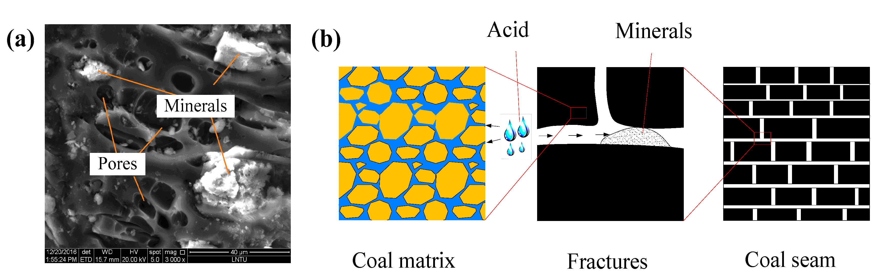
2.1. Permeability Enhancement by Acid Fracturing

Cleats in coal reservoirs are the place and channels where materials exchange with the outside, which significantly impact coal permeability. However, cleats in coal reservoirs are full of carbonate minerals and silicate minerals, like calcite, dolomite, hematite, pyrite, quartz, and kaolinite (Figure 1). For the acid fracturing technology, the coal seam is first fractured using one or several acid liquids, then the injected acid will spread to dissolve or corrode cements, minerals in pores and fractures. By means of chemical reactions, the connectivity between pores and fractures is enhanced, and thus the permeability of the coal reservoir is improved.
The principles of chemical reactions between different minerals and acid types vary. According to the type of reaction between minerals and injected acid in coal seam, acid fracturing can be divided into two main types, namely the hydrochloric acid (HCl) fracturing, and the hydrofluoric acid (HF) fracturing.
During the HCl acidification process a large amount of HCl is injected into the coal seam to react with the minerals. In the reaction of HCl and minerals, H+ migration in acid solution is mainly controlled by flow, filtration, etc. For a certain coal seams, the acid-coal reaction is constant and the acid is generally in excess, so the acid volume of the acid coal reaction is basically unchanged. Therefore, the H+ transfer coefficient and H+ mass fraction gradient are the key factors to control the rate of acid-coal reactions (Figure 2).
In the HCl-HF system, HF has the priority to react with all minerals in coal. The HCl reaction order is mostly zero, and the HF reaction order is 1. In the reaction with feldspar, HCl does not participate in the reaction, but it catalyzes the reaction between HF and feldspar, and its reaction rate increases with the mass fraction of HCl. From the view of this point, acid systems with low fractions of HF and high fractions of HCl are used to acidify coal seam containing abundant aluminosilicates [25].

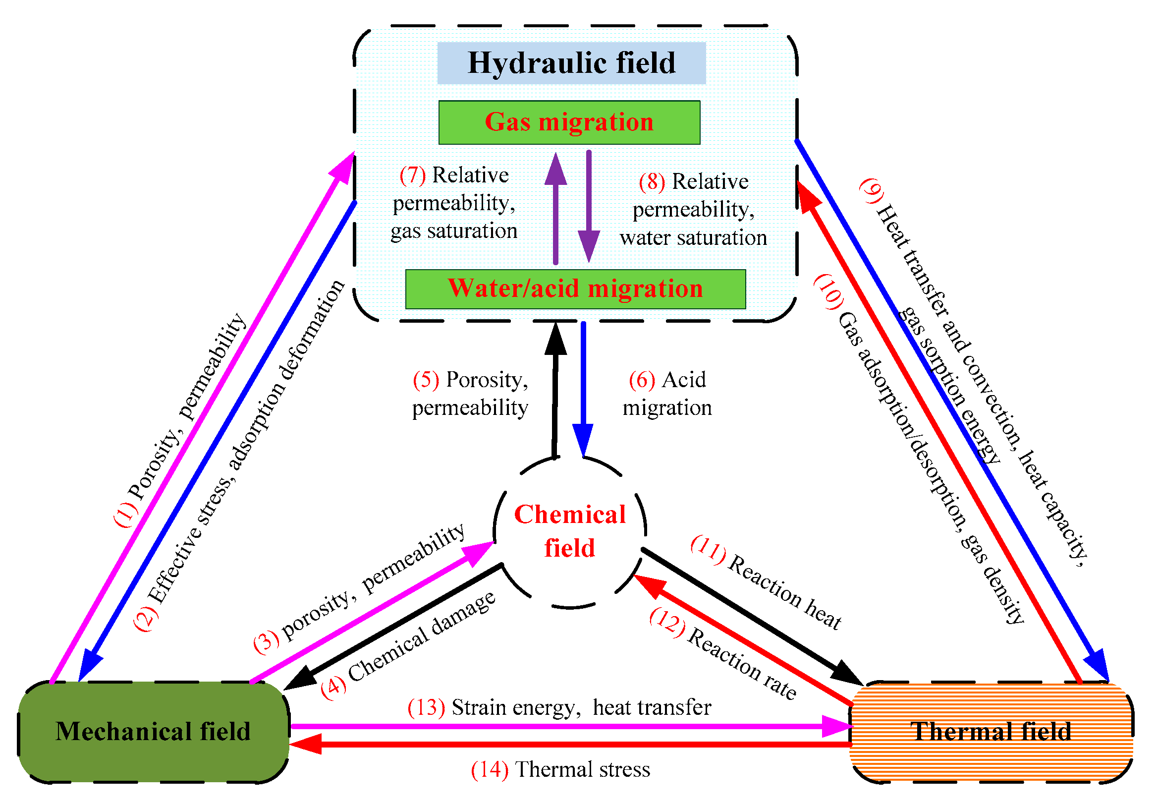
2.2. THMC Coupling Responses

The process of acid fracturing in coal seams involves the coupling responses of thermal transfer (T), hydraulic migration (H), coal deformation under mechanical stress (M), and chemical reactions (C), and these four fields interact with each other, as shown in Figure 3. We will give some insight into these interaction relationships among the various fields to reveal the mechanism of acid fracturing and further apply this technology to improve reservoir permeability, and thus enhance CBM recovery. The coupling responses can be described as follows:
  • For the mechanical field, the stress mainly determine the initiation and development of fractures in coal and rock, thus affecting their porosity and permeability, as well as the fluid (gas and water) seepage in coal seams. The improvement of the fracture network induced by mechanical stress provides more sites for chemical reactions. The change of strain energy is one of the forms for thermal transfer.
  • For the hydraulic field, the fluid migration controls the process of mass (gas, acid) transport and heat transfer. The reservoir pressure and two phase flow during AF-ECBM will affect the physical properties and effective stress of the coal seam, as well as the mechanical field. The seepage rate of fluid will affect the speed and spatial scope of chemical reactions between acid and minerals. The heat transfer by means of heat conduction and convection within a coal seam is promoted by hydraulic migration.
  • For the chemical field, the chemical reaction will consume minerals or blockages in coal seam, and increase the porosity and permeability. The strength of the corroded coal is reduced, and the stress field in coal seam is redistributed. Meanwhile, the chemical reaction process is accompanied by the consumption or generation of heat, and thus the temperature distribution is affected.
  • For the thermal field, the density and viscosity of fluids vary with the change of temperature in the coal seam, which significantly influences the fluid flow characteristics. The higher the temperature, the greater the activation energy and the more intense the molecular activity is. This promotes the desorption of adsorbed gas from the coal matrix and increases the rate of chemical reactions. Due to the change of temperature, the coal skeleton will also be deformed, which generates thermal stress and further affects the distribution of the stress field in the coal.

3. THMC Coupling Model for AF-ECBM Recovery Simulation

3.1. Basic Hypothesis

According to the above coupling relationships and occurrence conditions of the coal seam, the THMC coupling model is established for AF-ECBM recovery on the basis of the following assumptions:
(i) Coal mass is a dual-porosity medium composed of large number of pores and fractures. Both adsorbed and free gas coexist in the pores, while only free gas exists in fractures. The process of gas ad/desorption occurs instantaneously. Aqueous solution (water) only exists in fractures. The migration of gas and liquids in the fractures satisfies Darcy’s law, and the gas migration in pores satisfies Fick’s diffusion law. The gas sorption on the coal surface satisfies the Langmuir law. There is no phase transition between the gas, liquid and solid phases in the coal mass, and gas conforms to the ideal gas law.
(ii) Coal strength is controlled by both mechanical damage and chemical damage. Coal is characterized by strong heterogeneity, and the elastic modulus of coal obeys a Weibull distribution [26]:
f ( E ) = m E 0 ( E E 0 ) m 1 exp [ ( E E 0 ) m ]
where E is the Young’s modulus of coal, GPa; E0 is the average Young’s modulus of coal, GPa; m is the coefficient of heterogeneity.
(iii) The acid reaction rate is only related to the solute concentration and temperature. Minerals in the coal mass are uniformly distributed in the fractures. The reaction products of minerals and acids are soluble, which can be discharged out of coal seam in the back-flow process.
(iv) The tensile stress is positive, the compressive stress is negative. The gravity force of gas can be neglected.

3.2. Governing Equations of THMC Model

The entire process of acid fracturing in a coal seam is simulated using the THMC coupling model which consists of governing equations of coal deformation (mechanical), gas and liquid migration (hydraulic), heat transfer (thermal) and chemical reaction (chemical) fields, together with the coupling terms of porosity and permeability.

3.2.1. Governing Equations of Mechanical Field

Assume coal mass is an ideal linear elastic material, satisfying the generalized Hooke’s law. The action of fracturing and acidification on coal during AF-ECBM recovery will cause coal deformation. Considering the thermal expansion induced by the temperature change, and the matrix swelling induced by gas adsorption, the stress-strain relationship of coal can be expressed as [4,27]:
ε i j = 1 2 G σ i j ( 1 6 G 1 9 K ) σ k k δ i j + 1 3 α T ( T T 0 ) δ i j + 1 3 K α p p f δ i j + 1 3 ε s δ i j
where εij is the total strain; δij is the Kronecker delta with 1 for i = j and 0 for ij; G is the shear modulus, G = E*/2(1 + ν), MPa; E* is the equivalent Young’s modulus of coal, MPa; ν is the Poisson’s ratio, K is the volume modulus of coal, K = E*/3(1 − 2ν), MPa; αT is the thermal expansion coefficient, 1/K; T is the temperature of coal seam, K; T0 is the temperature of coal seam at initial state, K; αp is the Biot coefficient, αp = 1 − K/Ks; Ks is the volume modulus of coal skeleton, Ks = Es/3(1 − 2ν), MPa; εs is the volumetric strain of matrix swelling/shrinkage induced by gas sorption/desorption [28], εs = εLpm/(pL + pm), εL is the expansion coefficient of Langmuir adsorption; pL is the Langmuir pressure constant, MPa, pm is matrix gas pressure, MPa; pf is fluid pressure in fracture, MPa; pf = swpw + sgpg; pg is gas pressure, MPa; pw is the liquid pressure, MPa; sw is water saturation, sg is gas saturation, sw + sg = 1.
Based on damage mechanics, the equivalent elastic modulus of coal under damage conditions can be obtained [29]:
E = ( 1 D ) E 0
where D is the damage variable, E0 is the initial modulus of elasticity, GPa. The damage variable can be obtained using the maximum tensile stress criterion, and Mohr–Coulomb criterion.
According to the Cauchy formula, the relationship between strain and displacement is [8]:
ε i j = 1 2 ( u i , j + u j , i )
The static equilibrium relation of coal mass is shown as follows [30]:
σ i j , j + f i = 0
where fi is the volume stress in the i direction, MPa.
Combining Equations (2)–(5), the governing equation for mechanical field can be obtained:
G u i , j j + G 1 2 υ u j , j i α T K ( T T 0 ) , i α p p f , i K ε a , i + f i = 0

3.2.2. Governing Equation of Hydraulic Field

In the process of acid fracturing, the mass transport mainly consists of two parts—gas migration and acid liquid migration. The gas migration includes the following steps: the adsorbed gas desorbs from the pore surface to the pore space, and then diffuses from pores to fractures, and finally seeps from coal fractures to the extraction borehole [17]. The process of acid seepage mainly includes the acid fluid is first pumped into the coal fractures from the fracking borehole, and then spreads into the coal seam. The back-flowing process of acid fluids is the opposite.
According to the law of mass conservation, the mass balance equation of the fluid in the coal seam [31] is as follows:
m f l o w t + ( ρ f l o w × u f l o w ) = Q s
where mflow is the fluid content in unit volume coal, kg/m3; ρflow is the fluid density, kg/m3; t is time variable, s; uflow is fluid velocity, m/s; Qs is fluid source/sink term, kg/(m3·s).
The fluid content in the matrix and fractures of coal mass per unit volume is [32,33]:
{ m f w = s w ϕ f ρ f w m f g = s g ϕ f ρ f g = s g ϕ f M g p f g R T m m g = ϕ m ρ m g + ρ s ρ a V L p m P L + p m = ϕ m M g p m g R T + ρ s M g p a R T a V L p m P L + p m
where subscripts f, m represent the fractures and matrix pores, respectively, and the subscripts w, g represent acid fluid and gas, respectively; m is the fluid content, kg/m3; φf is fracture porosity and φm is matrix porosity; ρfw is the water density, kg/m3; ρfg and ρmg are the gas density in fracture and matrix respectively, kg/m3; ρa is the gas density under standard condition, kg/m3; ρs is coal skeleton density, kg/m3; Mg is the gas molar mass, kg/mol; VL is the Langmuir volume constant, m3/kg; PL is the Langmuir pressure constant, Pa; pa is atmospheric pressure, Pa; Ta is the reference temperature, K.
In the permeability enhancement process of acid fracturing in coal seams, the fluid in the coal mass is a gas-liquid two-phase flow [30]. According to the general Darcy’s law for multiple flows, the velocity for each fluid can be expressed as follows [34,35]:
{ u f w = k f k r w μ w p w u f g = k f k r g μ g p g
where kf is the absolute permeability of the coal mass, m2; krw, krg are the relative permeability for acid liquid (water) and gas respectively; μ is the dynamic viscosity, Pa·s; p is the fluid pressure, Pa; subscripts f, m represent fractures and pores and subscripts w, g represent acid liquid (water) and gas respectively. Substituting Equations (8) and (9) into Equation (7), we can obtain:
{ s w ρ w ϕ f t + s w ϕ f ρ w t ( k f k r w μ w ρ w p w ) = 0 s g ρ f g ϕ f t + s w ϕ f ρ f g t ( k f k r g μ g ρ f g p f g ) = 1 τ M g R T ( p m g p f g ) [ ϕ m T + ( 1 ϕ m ) ρ s ρ a V L P L T a ( P L + p m ) 2 ] p m t + [ p m T p a ρ s T a V L p m P L + p m ] ϕ m t ϕ m p m T 2 T t = 1 τ M g R T ( p m g p f g )
where τ is the desorption time of gas, which reflects the time taken for diffusion to progress between coal matrix and fractures to desorb 63.2% of the total adsorbed gas [36].

3.2.3. Governing Equation of Chemical Field

The chemical field mainly involves the consumption of acid solution and minerals during the acidification process. According to the mass conservation law, the change of acid with time is the total consumption of seepage, diffusion and chemical reactions. The governing equation of the chemical field can be obtained as follows [37]:
d ( φ f s w C A j ) d t ( C A j k f k w μ w p w ) D A j ς C A j + J A j = 0
where C A j is concentration of substance Aj, mol/l; ∇pw is pressure gradient of acid fluids, MPa; DAj is diffusion coefficient of acid fluids, ζ is shape factor, 1/m; J A j is chemical reaction rate of substance Aj, mol/(L·h).
According to the kinetic characteristics of chemical reaction, the reaction rate of the substance can be obtained as [25,38]:
J A j = k j C A j α j C B j β j = w j e E A j R T C A j α j C B j β j
where kj is reaction rate constant, (mol/L)0.5/h; wj is the frequency factor; αj, βj are concentration index of each substance in chemical reaction, E A j is the reaction activation energy, J/mol; R is the gas constant, where R = 8.314, J/(mol·K); T is the temperature, K.
By substituting Equations (9) and (12) into Equation (11), the governing equation of the chemical field can be obtained as follows:
d ( φ f s w C A j ) d t k f k w μ w p w C A j + w j e E A j R T C A j α j C B j β j = 0
Substances Aj and Bj are interrelated and mutually restricted, and the consumption of substances with reaction time can be expressed [39]:
C B j t = b j M B j a j M A j w j e E A j R T C A j α j C B j β j
The place where the acidification reaction occurs is determined by the shape of fracture extension caused by hydraulic fracturing, and the depth of acid solution immersed in the coal reservoir is controlled by the initial permeability, pressure gradient, acid viscosity and other properties of the coal reservoir.

3.2.4. Governing Equation of Temperature Field

Gas ad/desorption in coal seams is accompanied by the release/adsorption of heat. With the increase of mining depth, the temperature of the coal seam increases, which promotes gas desorption. The acidification reaction will consume/generate heat. Under the combined actions of thermal conduction and convection, an energy transfer occurs within the coal seam, thus the temperature distribution in the coal seam changes. The types of energy affecting the temperature distribution include internal energy, strain energy induced by coal deformation, energy caused by gas sorption, heat generated by fluid thermal convection, heat caused by heat conduction, and heat generated by the acidification reaction.
The total specific heat capacity of coal mass is a linear combination of the specific heat capacity of the coal skeleton, acid liquid, and gas [30,32]. It can be expressed as:
( ρ C ) t = ( 1 φ m φ f ) ρ s C s + φ m ρ m g C m g + s g φ f ρ f g C f g + s w φ f ρ w C w
where Cs, Cmg, Cfg, Cw are the specific heat capacities of coal skeleton, gas in matrix, gas and acid solution in fractures respectively, J/(kg·K).
The strain energy induced by coal deformation is mainly related to the volume strain, bulk modulus and thermal expansion coefficient of coal mass [40]:
Q T = T α T K v ε v t
where T is the temperature of coal, K; αT is thermal expansion coefficient of coal skeleton, 1/K; Kv is the volume modulus, MPa; εv is the volume strain.
The energy generated by gas adsorption is a function of the equivalent adsorption heat and the amount of adsorbed gas. The amount of gas adsorption is the intrinsic property of coal, which can be obtained by the Langmuir isothermal adsorption equation [32]:
Q a = q s t ρ c s ρ a V L p m P L + p m
where qst is equivalent adsorption heat, kJ/mol; ρcs is coal density, kg/m3; ρa is gas density under standard condition, kg/m3; pm is the gas pressure at the current temperature, Pa.
The heat generated by thermal convection via gas and acid migration in the coal mass is mainly the result of the interaction of fluid pressure and temperature gradients [30]:
Q t r = [ ( k f k f g μ g p f g ρ f g C f g + k f k w μ w p w ρ w C w ) T ]
The heat caused by thermal conduction in coal seam is the combined result of temperature gradient and coal conductivity [40]:
Q c = ( λ t T )
λ t = ( 1 φ f φ m ) λ c + ( φ m + s g φ f ) λ g + s w φ f λ w
where λc, λg and λw are the thermal conductivity coefficients of coal skeleton, gas and acid solution respectively, W/(m·K).
According to the energy conservation law, the governing equation of temperature field can be expressed as [30,32,40]:
[ ( ρ C ) t Δ T ] t + T α T K ε v t + q s t ρ c s ρ a V L p m P L + p m + Q t r + ( λ t T ) + Q c = Q T
In the above equation, the terms from the left to right correspond to the internal energy, strain energy, gas desorption induced energy, heat convection, heat conduction, and the heat generated by acidifizing reaction, and the energy source/sink term.

3.2.5. Porosity and Permeability

We assume that the acid solution cannot enter the micro-pores within coal, in other words, the acid solution only migrates in fractures. The porosity is considered to relate to the change of temperature, stress and gas adsorption. The porosity in matrix is defined as [33]:
d ϕ m = ϕ m α p 1 + b 0 K / a 0 K f ( d ε s + α T d T d ε v )
where Kf is to modified fracture stiffness, N/m; Kf = aKn; a0 is the initial matrix width, m; b0 is the initial fracture width, m.
After integrating and arranging Equation (22), we can recover:
φ m = α p 1 + ( φ m 0 α p 1 ) exp [ ( 1 + b 0 K a 0 K f ) 1 Δ ε e ]
where Δεe = −εs + εs0αTT + αT T0εv + εv0.
Fracture porosity is the ratio of fracture volume to total coal mass volume, which is closely related to the width of the fracture. A large number of new fractures are generated in the process of acid fracturing, thus the fracture porosity is greatly improved. In addition, the acid fluid reacts with the minerals in fracture, and depletes the minerals to open the fracture aperture, and increases the fracture porosity. The fracture porosity can be expressed as [30]:
φ f = φ f 0 + ( α φ f 0 ) [ ( ε v + p m K s ε s α T T ) ( ε v 0 + p m 0 K s ε s 0 α T T 0 ) ] + Δ m ρ r o c k
where Δm is the dissolved mineral mass per volume, kg; ρrock is the density of dissolved mineral, kg/m3.
The relationship between permeability and fracture porosity of porous media is basically subject to kozeny-carman equation, and the permeability can be obtained as [7]:
k f k f 0 = ( φ f φ f 0 ) 3 = [ 1 + ( α φ f 0 - 1 ) ( Δ ε v + Δ p / K s Δ ε a Δ α T T ) + Δ m ρ r o c k φ f 0 ] 3
Considering the mechanical damage, the permeability during AF-ECBM recovery can be expressed as [26,29]:
k = k 0 ( 1 + D ξ ) [ 1 + ( α φ f 0 - 1 ) ( Δ ε v + Δ p / K s Δ ε a Δ α T T ) + Δ m ρ r o c k φ f 0 ] 3
where ξ is the jump factor of mechanical damage in fracturing process, D is the damage variable.
Combing the governing equations of Equations (6), (10), (13), (21)–(24) and (26), the THMC coupled model for acid fracturing in coal seams is proposed.

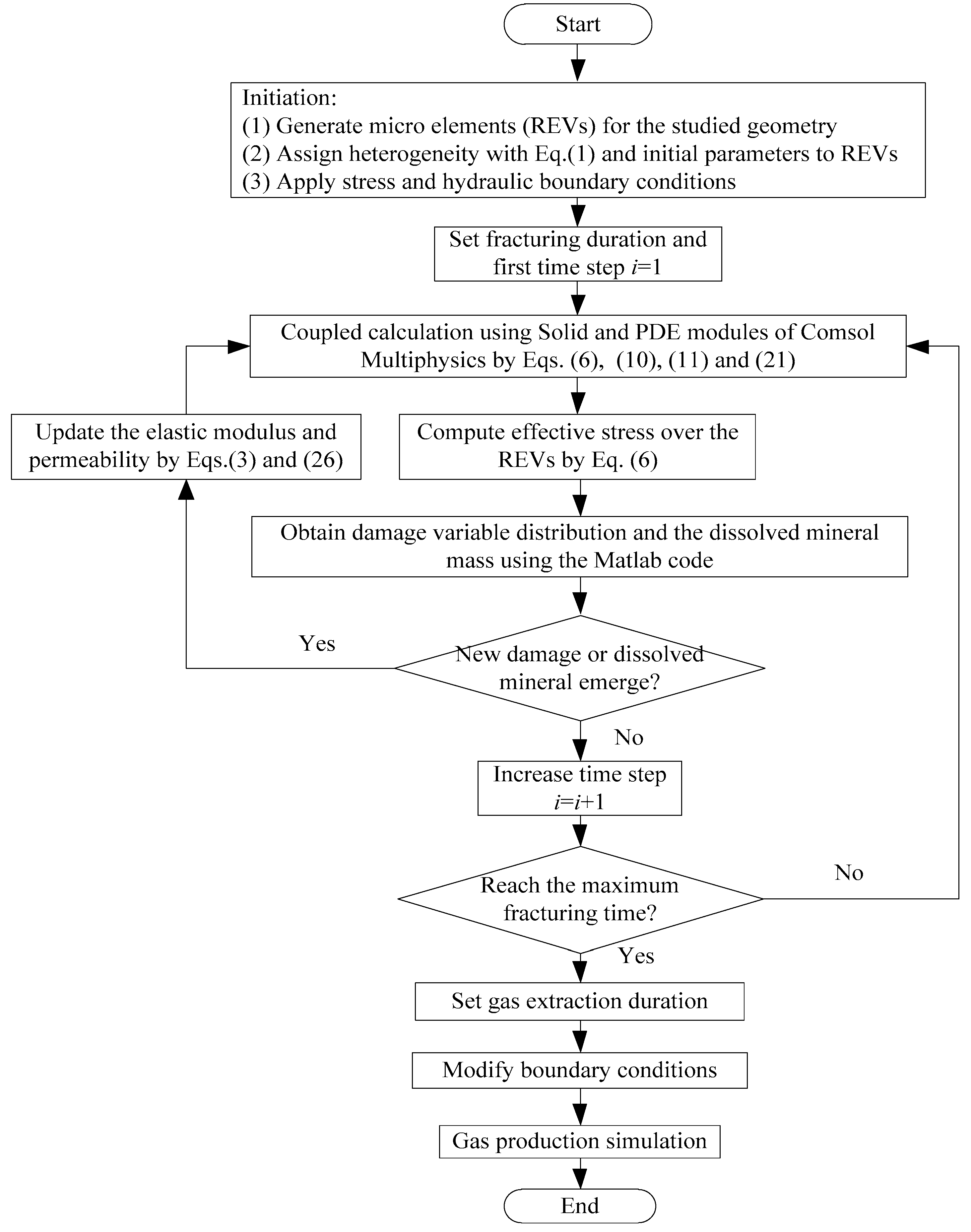
3.2.6. Solving Process of the THMC Coupled Model

According to the determined governing equations of the mechanical, hydraulic, chemical and thermal fields, the PDE equation of each field is customized. The large-scale iterative calculation is realized by linking COMSOL with MATLAB, and finally reproduced the coupling responses of acid fracturing to improve reservoir permeability. This finite element method approach requires that the damage state and the damage-induced alteration of elastic modulus and permeability are continually updated with new damage occurs. Figure 4 shows a flow chart for the THMC coupled modeling approach [8].
The basic procedures are summarized as follows:
(i) After the studied geometry has been built, the model is discretized into a set of microscopic elements (REVs). Then the Monte-Carlo method is utilized to generate the initial elastic modulus distribution by Equation (1). The initial parameters are assigned to REVs as well as the stress and acid hydraulic boundary conditions. Acid fracturing is a transient process, so that the duration of this process is defined and divided into several steps.
(ii) For the first step i = 1, a coupled calculation is performed using Solid module and PDE modules by Equations (6), (10), (11) and (21). The effective stresses and pore pressure for each of the REVs are computed.
(iii) Then, the damage tensor is calculated using the maximum tensile stress criterion (tensile stress state), and the Mohr–Coulomb criterion (compressive stress state). The dissolved mineral mass per volume is also checked in these processes. Furthermore, if new damage and dissolved mineral emerges compared with the former damage variable and dissolved mineral mass, the elastic modulus and the permeability are modified following Equations (3) and (26).
(iv) The updated material parameters are used to define a new equilibrium and steps (ii) and (iii) are repeated to examine the damage state. During the acid fracturing process, fractures will propagate along the damage zone. If there no new damage emerges, the next time step is loaded until the maximum fracturing time is reached.
(v) Finally, when the fracturing is finished, we set gas extraction duration and change the corresponding boundary condition to simulate the gas production process.

4. Numerical Simulation of Acid Fracturing Enhanced CBM Recovery

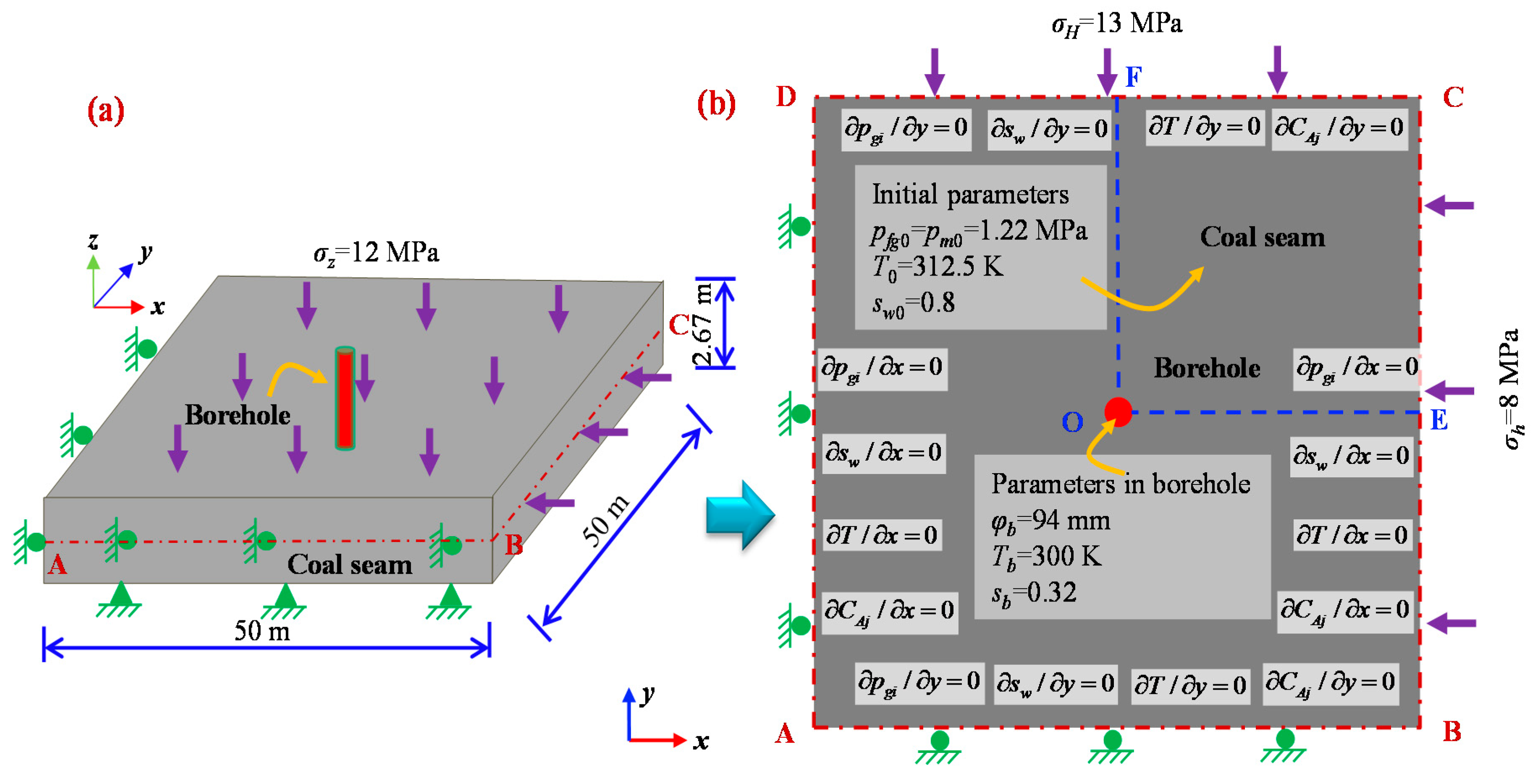
4.1. Physical Model Setting

The Sihe coal mine located in Shanxi Province, China, mainly recovery coal from the Shanxi group (P1s) and Taiyuan group (C2t-P1t) of Carboniferous-Permian coal-bearing strata. The total thickness of the coal is 14.67 m with 15 seams, showing a coal-bearing coefficient of 10.8%. Among these coal seams, the #3 and #15 seams have large and stable thickness. Coal seam #15 is located at the top of the Taiyuan group, with a main roof of K2 limestone and an average distance of 36.38 m from the #3 coal seam, 76 m from K7 sandstone and 36.38 m from the #9 coal seam. The thickness of coal seam #15 ranges from 1.08 m to 5.45 m, with an average of 2.67 m. The dip angle of the coal seam ranges from 2° to 10°.
According to the geological background of coal seam #15, a three-dimensional geometry of 50 m × 50 m× 2.67 m is adopted, as shown in Figure 5a. To simplify the calculations, we use the central slice of this 3D geometry, namely a two-dimensional area of 50 m × 50 m as shown in Figure 5b, to carry out the simulation of AF-ECBM recovery using the established THMC coupled model. In this study, the initial values of reservoir pressure, temperature, permeability and water saturation are 1.22 MPa, 312.5 K, 0.151 mD and 0.8, respectively. A borehole with 94 mm in diameter is located in the center of the simulated domain. This borehole is first used as the fracking hole, and then is applied as the extraction hole. During the acid fracturing stage, the pressure around the borehole is set as 24 MPa with HCl and HF concentrations of 3.60 mol/L and 0.9 mol/L, respectively, within the injected fluid, and this stage is continued for 8000 s. After that, during the stage of gas extraction, the bottom pressure is changed to 0.15 MPa to recovery the coalbed methane, and this stage is continued for 300 days. The bottom and left sides of the geometry are set as the roller boundary, the top and right sides are subject to a maximum horizontal stress of 13 MPa and a minimum horizontal stress of 8 MPa. The 2D geometry in Figure 5b taken out is a slice parallel to the horizontal plane of 3D geometry in Figure 5a. Accordingly, the maximum and minimum horizontal stresses are applied to the boundary to obtain an approximate set of boundary conditions in situ. If we applied the same stress to the opposite pairs of edges of the model, it would be difficult to achieve the stress balance of the model because none of the points in the model are fixed. In this way, the problem becomes a dynamic problem rather a static problem, for which it is difficult to obtain a numerical solution. Hence, the bottom and left sides of the geometry are set as the roller boundary, and it is relatively accurate for the solution around a borehole far from the boundary. The cylindrical polar geometry may avoid the non-physical boundary conditions at the edges of the model, but it cannot reflect the direction of different horizontal stresses, which limits the expansion direction of induced cracks. Therefore, we use a square geometry rather than a cylindrical polar geometry. The sections O-E and O-F are designed to measure the variation of gas pressure. As shown in Figure 5, all the external boundaries are insulated for mass transport and heat transfer, except for the fracking/extraction hole. 1256 elements and 25,647 degrees of freedom are generated for the entire domain by a distributed tetrahedral mesh method. The parameters involved in the simulation are obtained from the results of laboratory experiments and related literatures, as shown in Table 1. The experiments are carried out in the mining engineering laboratory of Liaoning Technical University. The tensile strength of coal is measured by indirect tensile strength method using a servo-controlled rock mechanics test system. The Poisson’s ratio, cohesion, and internal friction angle of coal are recovered by the uniaxial compressive strength method using the same test system.

4.2. Simulation Schemes

In order to explore the enhancement effect of acid fracturing, four scenarios with different permeability improving methods have been proposed to carry out these simulations. The evolution of key parameters including damage variable (mechanical, chemical), reservoir permeability, gas pressure, gas production of the four scenarios are comparatively analyzed:
Scenario I (D-CBM): Coalbed methane recovery is directly carried out without acidizing or fracturing stimulation.
Scenario II (A-ECBM): Enhanced coalbed methane recovery is carried out with acidizing stimulation only. Under this condition, the reservoir permeability is improved by injection of acid liquid without hydraulic fracturing.
Scenario III (F-ECBM): Enhanced coalbed methane recovery is carried out with hydraulic fracturing stimulation only. Under this condition, the reservoir permeability is improved by hydraulic fracturing without injection of acid.
Scenario IV (AF-ECBM): Enhanced coalbed methane recovery is carried out with both acid injection and hydraulic fracturing. Under this condition, the reservoir permeability is improved by both hydraulic fracturing and acid injection.

4.3. Results and Discussion

The parameters such as damage variable, reservoir permeability, gas pressure and gas production are important indexes to evaluate the effect of permeability improvement for a specific stimulation method. The simulated results of these four scenarios are shown as follows:

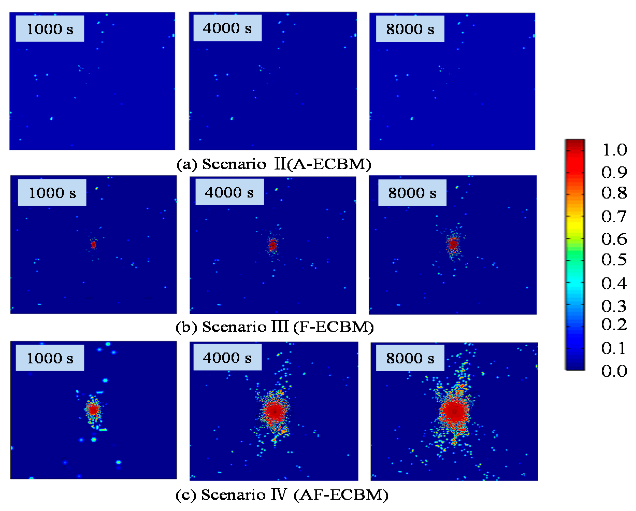
4.3.1. Distribution of Damage Variable

The increase of coal permeability is essentially caused by mechanical/chemical damage on coal, which leads to large amount of pores and fractures initiation, and connection with each other. Undoubtedly, the scope of damage zone in coal seam is a reasonable index to evaluate the effect of different permeability enhancement methods. Under the same conditions, a larger scope of damage zone corresponds to a better effect of permeability enhancement. The damage distribution of scenarios II-IV at different time periods is shown in Figure 6.
The blue area represents the intact coal mass, and the red area represents the complete damaged coal mass. The damage zones around the borehole of the three stimulation methods are obvious. The scope of damage zone varies for different permeability stimulation methods. The damage variable ranges from 0 to 1. The scattered damage zones in the figures are caused by the heterogeneity of coal mass under the mechanical stress.
In Figure 6, the range of the damage zones of different stimulation methods increases with the treatment time. The acid fracturing (AF-ECBM) method shows the most obvious change in damage zone, followed by the hydraulic fracturing (F-ECBM) method, and the acidification (A-ECBM) method has the least obvious change. The reason is that the acid fluid mainly penetrates into the coal mass by means of diffusion in the A-ECBM process. However, the diffusion rate is relatively low, which leads to a weak chemical damage in coal seam, with only ~20 cm depth after immersed 2 h, but for F-ECBM recovery, the high-pressure fracturing water forces coal mass to experience mechanical damage, and accelerates the propagation of fractures, and finally leading to an obvious change of the damage zone. For AF-ECBM recovery, the hydraulic fracturing is combined with acidification. The distribution of variable damage for this method includes both mechanical and chemical aspects. These two damages influence and promote each other to form the effect of “1 + 1 > 2”.
At the same time, the ranges of the damage zones induced by different stimulation methods are quite different. After treatment for 100 s, all three stimulation methods show no significant differences in the damage zone due to the short treatment time. With the increase of time, the differences in the damage zones between different stimulation methods (A-ECBM, F-ECBM, AF-ECBM) is enlarged. The longer the action time, the greater the differences will be.
The distribution of the damage zones of F-ECBM and AF-ECBM is characterized by obvious directivity. The damage zone is along the vertical direction—the same as the maximum stress. This shows that the development pattern of the damage zone is controlled by the direction of the maximum stress in the coal seam.

4.3.2. Distribution of Elastic Modulus

The elastic modulus is an important physical parameter reflecting the strength of coal. In general, the greater the elastic modulus of coal, the higher the strength will be. The change of elastic modulus is similar to that of damage (Figure 7). The elastic modulus has a linear relationship with the damage variable, as presented in Equation (3). The elastic modulus of coal seam ranges from 0 to 4.5 GPa. When damage occurs in a coal mass, the elastic modulus will decrease at the corresponding position. The reduction variation of elastic modulus is positively correlated with the damage variable, namely, greater damage in the coal seam corresponds to more a larger decrease in the elastic modulus. Due to the heterogeneity of the initial elastic modulus, the elastic modulus is scattered in coal reservoir. Similar with the distribution of damage variable, the AF-ECBM has the largest area of reduction in elastic modulus, followed by F-ECBM and A-ECBM. The reduction zone of elastic modulus spreads along the direction of the maximum horizontal stress.

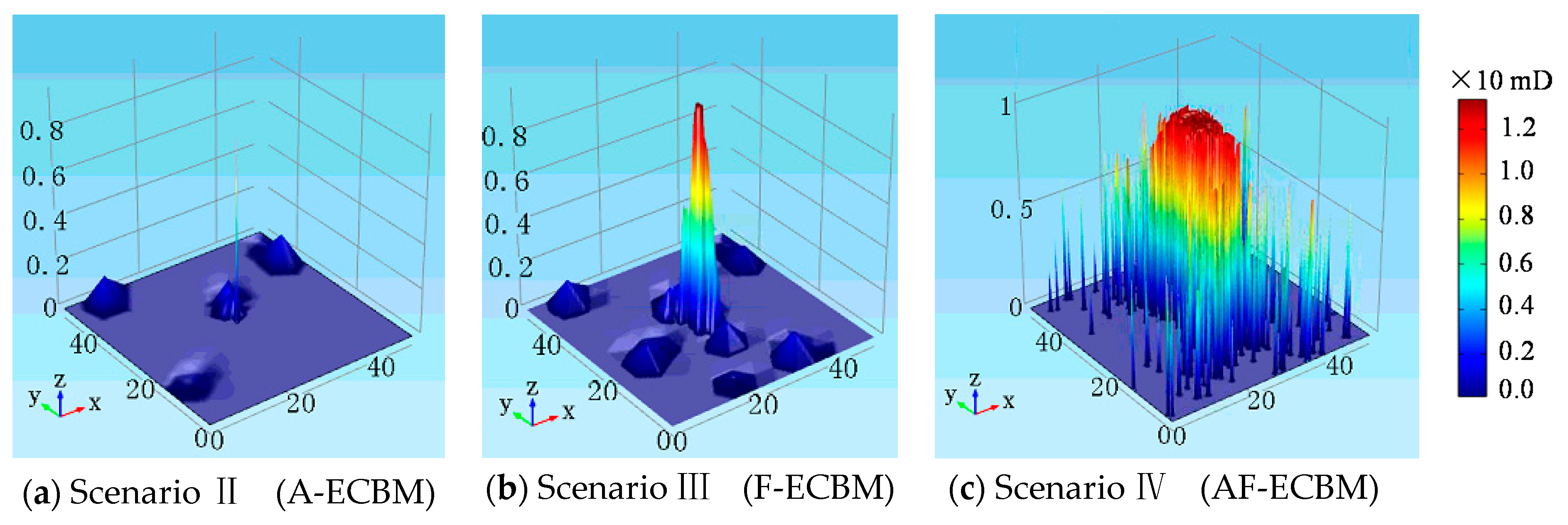
4.3.3. Distribution of Reservoir Permeability

The resulting coal permeability is the most direct index to evaluate the enhancement effect of a stimulation method. To visually compare the differences between different stimulation methods (A-ECBM, F-ECBM, AF-ECBM), post-processing was used to generate the 3D distribution map of reservoir permeability after treatment for 8000 s (~2 h), as shown in Figure 8. The reservoir permeability ranges from 0.151 mD to 12 mD. In terms of both the magnitude and distribution range of reservoir permeability, the acidification fracturing (AF-ECBM) is obviously greater than the hydraulic fracturing (F-ECBM) and acidification (A-ECBM), indicating a better enhancement effect of the acidification fracturing method. As mentioned in Section 3.2.5, the reservoir permeability is the combined result of coal deformation, temperature changes, gas sorption, mechanical and chemical damage. Comparing Figure 6c and Figure 7 with Figure 8, the permeability distribution is almost located in the damaged zone, illustrating that the mechanical and chemical damage dominate the evolution of permeability when the coal seam is fractured. When acid fracturing is applied in a coal seam, the reservoir permeability gradually increases with the decrease of distance from the fracking borehole. With the heterogeneity of coal seams and the directivity of the applied stress, the distribution of permeability fluctuated along the fracture expansion direction. The stress around the fracking borehole is redistributed, with a stress concentration occurs within the range of 0~5 m, resulting in the greater increment of permeability, as shown in Figure 8.

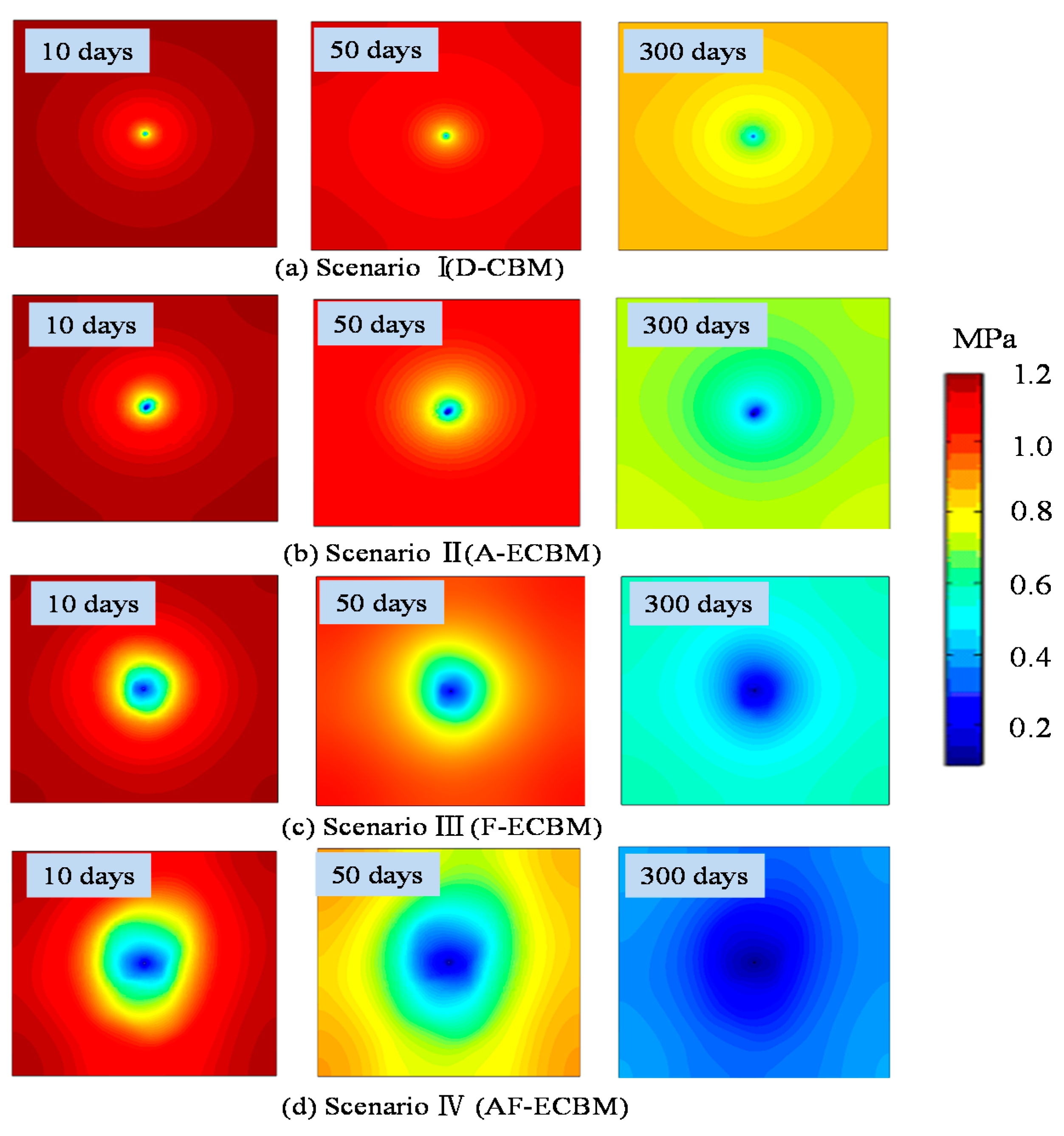
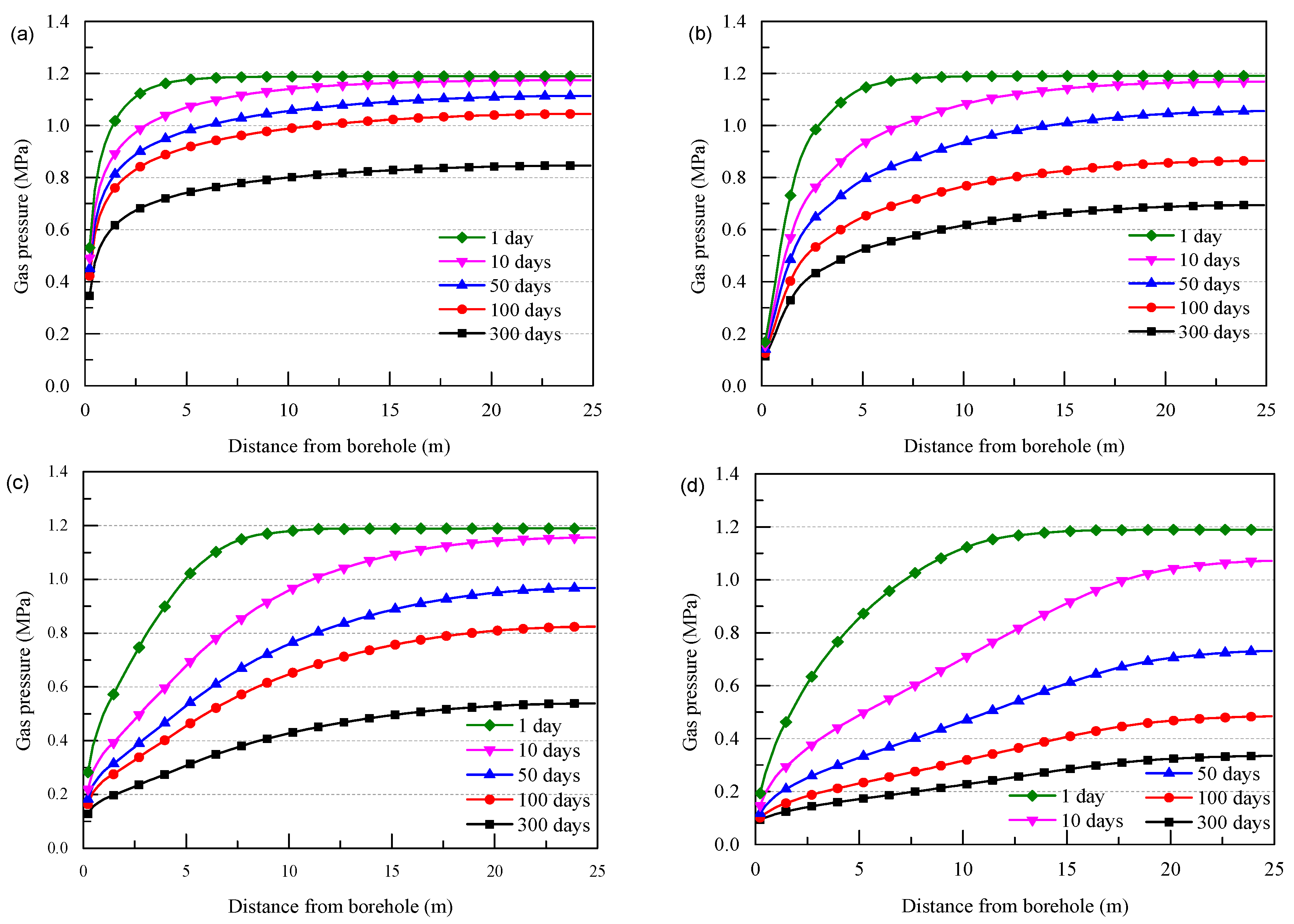
4.3.4. Evolution of Gas Pressure

The main purpose of permeability enhancement is to effectively recovery coalbed methane from coal seams. Hence, the evolution of gas pressure in coal seams during gas extraction is a primary criterion for evaluating the stimulation effect in engineering practice.
After treating the coal seam for 8000 s with different stimulation methods (A-ECBM, F-ECBM, AF-ECBM), the gas extraction process is then simulated. Considering the scenario of gas extraction without stimulation, the distribution contour of gas pressure for different recovery schemes after 10, 50 and 300 days’ extraction are shown in Figure 9, respectively.
In Figure 9, the reduction range of gas pressure in the recovery schemes permeability stimulations (A-ECBM, F-ECBM, AF-ECBM) is larger than that of direct extraction (D-CBM) without treatment for the same extraction time. With the increase of extraction time, the difference gradually enlarges. After 10 days of extraction, the pressure drop zone of all stimulated schemes has reached the edge of the geometry, except for the direct extraction scheme. The pressure drop zones of D-CBM and A-ECBM recoveries were distributed in concentric circles, while these of F-ECBM, AF-ECBM recoveries were distributed in an irregular shape with an obviously directional pressure drop range. After 50 days of extraction, the gas pressure drop zone of the D-CBM recovery scheme gradually reaches the edge of the geometry, while the gas pressure drop range and magnitude of the other three stimulation schemes are further enlarged. The gas pressure in the entire geometry for the scheme of extraction after acid fracturing (AF-ECBM) was reduced to less than 0.8 MPa, indicating a high AF-ECBM recovery efficiency. After 100 days of extraction, the effective extraction area of the direct extraction scheme (D-CBM) and the acidification extraction (A-ECBM) is still small, while the effective extraction area of hydraulic fracturing (F-ECBM) and acid fracturing (AF-ECBM) is large. After extraction for 300 days, the gas pressure of all extraction schemes is further reduced, especially after treatment with acid fracturing with gas pressure <0.4 MPa. The above results show that the efficiency of gas extraction after acid fracturing (AF-ECBM) is the highest, followed by hydraulic fracturing (F-ECBM) and acidification (A-ECBM), and the efficiency of direct extraction (D-CBM) is relatively poor.
Comparing Figure 9 with Figure 8, the acid fracturing can induce a large area of permeability increase near the borehole, which greatly improves the migration of coalbed methane towards the borehole during gas extraction. The larger the area of permeability increase, the greater the reduction of gas pressure in the coal seam will be. That is reason why acid fracturing (AF-ECBM) has a high gas extraction efficiency.
In order to quantitatively study the variation law of gas pressure at different places in coal seam, the gas pressure of different extraction schemes on reference line O-B at 1, 10, 50, 100 and 300 days are extracted and plotted in Figure 10.
As shown in Figure 10a, the gas pressure of the direct extraction scheme (D-CBM) gradually decreases with the increase of extraction time. At the same time, the gas pressure near the extraction borehole is lower than that near the edge of the geometry, forming a pressure drop funnel. Here, we take 10% reduction of gas pressure as the reference value of the pressure drop funnel. The radius of the pressure drop funnel increased from ~2.5 m (day 1) to ~25 m (300 days).
In Figure 10b, the radius of the pressure drop funnel of acidification-enhanced recovery (A-ECBM) has reached ~5.0 m after 1 day of gas extraction, compared to ~2.5 m with direct extraction. After the same extraction time, the gas pressure decreases more rapidly, especially in the initial period of 10–50 days. After 300 days’ extraction, the gas pressure within the entire geometry has been reduced to <0.6 MPa.
As presented in Figure 10c, the gas pressure of hydraulic fracturing enhanced recovery (F-ECBM) decreases more rapidly with time due to its greater permeability enhancement. However, the shape of the gas pressure curve is obviously different from that of the D-CBM and A-ECBM recoveries. The radius of the pressure drop funnel at day 1 is 8.0 m, which is larger than that of the previous two schemes. During the initial period of extraction (10~50 days), an obvious fast gas pressure drop is observed. After 300 days of extraction, the gas pressure in the entire geometry has been decreased to <0.55 MPa.
In Figure 10d, the gas pressure of acid fracturing-enhanced recovery (AF-ECBM) gradually decreases with the extraction time, and the shape of the gas pressure curve is basically similar to that of F-ECBM recovery. After 1 day or recovery, the radius of the pressure drop funnel is ~15.0 m, which is larger than that of the other three schemes. At the initial period of 10–50 days, gas pressure drops more rapidly than in the other schemes. After 300 days of extraction, the gas pressure in the entire simulated geometry has been reduced to <0.3 MPa.
To summarize, the effect of enhancement is as follows: AF-ECBM > F-ECBM > A-ECBM > D-CBM, according to the gas pressure change range and speed during gas extraction.

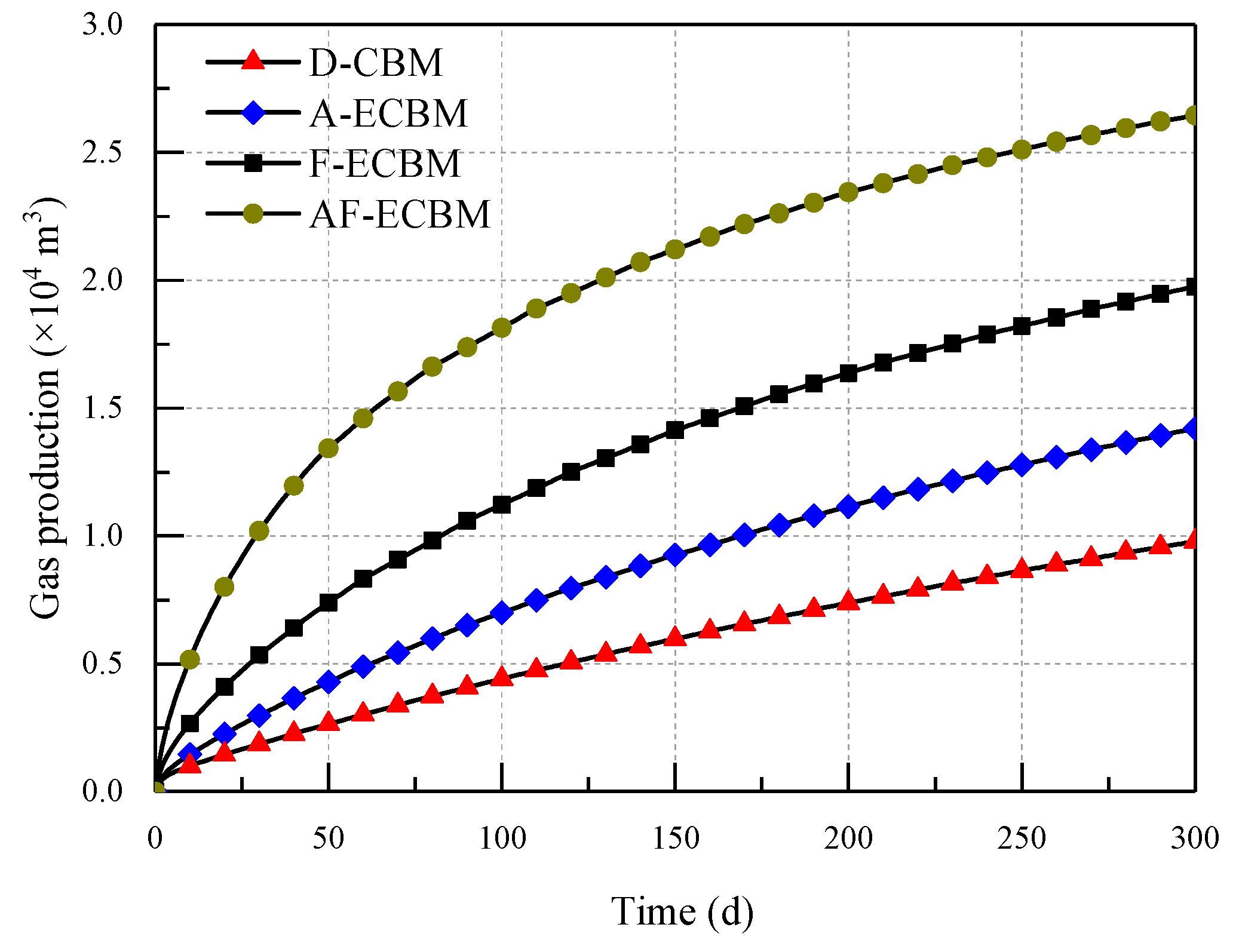
4.3.5. Variation of Gas Production

After implementing acidification measures to enhance the permeability, hydraulic fracturing and acid fracturing, gas extraction simulations are carried out. The variation of gas production with time of different schemes (D-CBM, A-ECBM, F-ECBM, AF-ECBM) are calculated and shown in Figure 11.
It can be seen from Figure 11, the gas production increases with the increase of extraction time. The gas production rate during the initial extraction period is larger than that in the later period according to the curve slope of gas production, showing the reduction trend of gas production rate with the increase of time. As far as gas production is concerned, the order is AF-ECBM > F-ECBM > A-ECBM > D-CBM for the same time. For instance, the gas production after 300 days for these schemes is 26,454 m3, 19,760 m3, 14,205 m3 and 9,788 m3, respectively. The gas production rate in the first 100 days of acid fracturing (AF-ECBM) and hydraulic fracturing (F-ECBM) is obviously greater than with the other two schemes (A-ECBM, D-CBM). After 100 days, the gas production rate is basically similar due to the huge gas pressure drop and thus low pressure gradient between reservoir and borehole.
In summary, the degree of coal mass damage caused by acidification, hydraulic fracturing and acid fracturing increases successively, causing an increasing improvement of reservoir permeability, and accordingly an increased efficiency of gas recovery from the coal seam. The acid fracturing enhancement method in coal seams is characterized by both mechanical and chemical damage, which is more likely applied to increase gas recovery ratio in ultra-low permeability reservoir.

5. Conclusions

(1) This numerical simulation, calibrated by laboratory data, suggests that acid fracturing is an efficient way to enhance reservoir permeability. The complex process of acid fracturing-enhanced coalbed methane recovery involves coupling responses among chemical reactions, mass migration in the form of two-phase flow, along with heat transfer (thermal conduction and convection), and coal deformation.
(2) Based on the laws of mass and energy conservation, the THMC coupling model for acid fracturing-enhanced CBM recovery is derived, including the governing equations of the thermal field, hydraulic field, mechanical field and chemical field, as well as the coupling terms of permeability and porosity. Numerical simulations based on this THMC model using a 2D geometry can accurately simulate and reproduce the process of acid fracturing.
(3) Several key parameters including damage variable, elastic modulus, permeability, gas pressure and gas production of different enhancement schemes are comparatively analyzed to explore the permeability enhancement effect. The gas production order is AF-ECBM > F-ECBM > A-ECBM > D-CBM, showing the priority of acid fracturing method for gas recovery from ultra-low permeability coal seams.

Author Contributions

All authors contributed equally to this work. C.F., M.L., H.Z., Z.Y., Z.L. and S.L. are the main authors of this work. C.F., H.Z., Z.Y. and Z.L. wrote the paper. S.L., M.L. and C.F. supported the research in terms of both scientific and technical expertise. All authors have been involved in the manuscript preparation.

Funding

This research was funded by the National Natural Science Foundation of China (Grant Nos. 51674132 and 51874159), the Project supported by the Postdoctoral Science Foundation of China (Grant No. 2018M641675), the Open Projects of State Key Laboratory of Coal Resources and Safe Mining, CUMT (Grant No. SKLCRSM15KF04), the Research Fund of State Key Laboratory Cultivation Base for Gas Geology and Gas Control (Henan Polytechnic University) (Grant No. WS2018B05), and the Basic Research Project of Key Laboratory of Liaoning Provincial Education Department (Grant No. LJZS004).

Acknowledgments

The authors would like to thank all editors and anonymous reviewers for their comments and suggestions.

Conflicts of Interest

The author, Mingkun Luo, is financially supported by the Postdoctoral Science Foundation of China rather than the Center of Technology, Shanxi Lu’an Mining (Group) Limited Liability Company. The authors declare no competing financial interest with all the institutions.

References

  1. Beamish, B.B.; Crosdale, P.J. Instantaneous outbursts in underground coal mines: An overview and association with coal type. Int. J. Coal Geol. 1998, 35, 27–55. [Google Scholar] [CrossRef]
  2. Fan, C.; Li, S.; Luo, M.; Du, W.; Yang, Z. Coal and gas outburst dynamic system. Int. J. Min. Sci. Technol. 2017, 27, 49–55. [Google Scholar] [CrossRef]
  3. Wang, G.; Li, W.; Wang, P.; Yang, X.; Zhang, S. Deformation and gas flow characteristics of coal-like materials under triaxial stress conditions. Int. J. Rock Mech. Min. Sci. 2017, 91, 72–80. [Google Scholar] [CrossRef]
  4. Liu, T.; Lin, B.; Yang, W.; Zhai, C.; Liu, T. Coal permeability evolution and gas migration under non-equilibrium state. Transp. Porous Media 2017, 118, 393–416. [Google Scholar] [CrossRef]
  5. Lv, Y.M.; Tang, D.Z.; Xu, H.; Luo, H.H. Production characteristics and the key factors in high-rank coalbed methane fields: A case study on the Fanzhuang Block, Southern Qinshui Basin, China. Int. J. Coal Geol. 2012, 96–97, 93–108. [Google Scholar] [CrossRef]
  6. Yang, Y.; Zhang, C.W.; Tian, H.J.; Chen, W.G.; Peng, X.D.; Zhang, H. The pilot appraisal of acid fracturing of coalbed methane reservoir in southeast Qinshui Basin, China. Earth Sci. Res. J. 2016, 20, C1–C6. [Google Scholar] [CrossRef]
  7. Wang, G.; Wang, K.; Wang, S.; Elsworth, D.; Jiang, Y. An improved permeability evolution model and its application in fractured sorbing media. J. Nat. Gas. Sci. Eng. 2018, 56, 222–232. [Google Scholar] [CrossRef]
  8. Fan, C.; Li, S.; Luo, M.; Yang, Z.; Lan, T. Numerical simulation of hydraulic fracturing in coal seam for enhancing underground gas drainage. Energ. Explor. Exploit. 2019, 37, 166–193. [Google Scholar] [CrossRef]
  9. Gao, J.F.; Xing, H.L.; Turner, L.; Steel, K.; Sedek, M.; Golding, S.D.; Rudolph, V. Pore-Scale Numerical Investigation on chemical stimulation in coal and permeability enhancement for coal seam gas production. Transp. Porous Media 2017, 116, 335–351. [Google Scholar] [CrossRef]
  10. Wang, G.; Chu, X.; Yang, X. Numerical simulation of gas flow in artificial fracture coal by three-dimensional reconstruction based on computed tomography. J. Nat. Gas Sci. Eng. 2016, 34, 823–831. [Google Scholar] [CrossRef]
  11. Ji, L.; Settari, A.; Sullivan, R.B. A novel hydraulic fracturing model fully coupled with geomechanics and reservoir simulation. SPE J. 2009, 14, 423–430. [Google Scholar] [CrossRef]
  12. Huang, B.X.; Huang, C.M.; Cheng, Q.Y. Hydraulic fracturing technology for improving permeability in gas-bearing coal seams in underground coal mines. J. S. Afr. I. Min. Metall. 2012, 112, 485–495. [Google Scholar]
  13. Adachi, J.; Siebrits, E.; Peirce, A.; Desroches, J. Computer simulation of hydraulic fractures. Int. J. Rock Mech. Min. Sci. 2007, 44, 739–757. [Google Scholar] [CrossRef]
  14. Song, Y.; Jiang, B.; Lan, F.J. Competitive adsorption of CO2/N2/CH4 onto coal vitrinite macromolecular: Effects of electrostatic interactions and oxygen functionalities. Fuel 2019, 235, 23–38. [Google Scholar]
  15. Wong, S.; Law, D.; Deng, X.; Robinson, J.; Kadatz, B.; Gunter, W.D.; Fan, Z. Enhanced coalbed methane and CO2 storage in anthracitic coals—micro-pilot test at South Qinshui, Shanxi, China. Int. J. Greenh. Gas Control 2007, 1, 215–222. [Google Scholar] [CrossRef]
  16. Kumar, H.; Elsworth, D.; Mathews, J.P.; Liu, J.; Pone, D. Effect of CO2 injection on heterogeneously permeable coalbed reservoirs. Fuel 2014, 135, 509–521. [Google Scholar] [CrossRef]
  17. Wu, Y.; Liu, J.S.; Elsworth, D.; Chen, Z.W.; Connell, L.; Pan, Z.J. Dual poroelastic response of a coal seam to CO2 injection. Int. J. Greenh. Gas Control 2010, 4, 668–678. [Google Scholar] [CrossRef]
  18. Durucan, S.; Shi, J.Q. Improving the CO2 well injectivity and enhanced coalbed methane production performance in coal seams. Int. J. Coal Geol. 2009, 77, 214–221. [Google Scholar] [CrossRef]
  19. Yan, F.Z.; Lin, B.Q.; Zhu, C.J.; Shen, C.M.; Zou, Q.L.; Guo, C.; Liu, T. A novel ECBM extraction technology based on the integration of hydraulic slotting and hydraulic fracturing. J. Nat. Gas Sci. Eng. 2015, 22, 571–579. [Google Scholar] [CrossRef]
  20. Lu, C.P.; Dou, L.M.; Zhang, N.; Xue, J.H.; Liu, G.J. Microseismic and acoustic emission effect on gas outburst hazard triggered by shock wave: A case study. Nat. Hazards 2014, 73, 1715–1731. [Google Scholar] [CrossRef]
  21. Vassilev, S.V.; Kitano, K.; Takeda, S.; Tsurue, T. Influence of mineral and chemical-composition of coal ashes on their fusibility. Fuel Process. Technol. 1995, 45, 27–51. [Google Scholar] [CrossRef]
  22. Balucan, R.D.; Turner, L.G.; Steel, K.M. Acid-induced mineral alteration and its influence on the permeability and compressibility of coal. J. Nat. Gas Sci. Eng. 2016, 33, 973–987. [Google Scholar] [CrossRef]
  23. Laubach, S.E.; Marrett, R.A.; Olson, J.E.; Scott, A.R. Characteristics and origins of coal cleat: A review. Int. J. Coal Geol. 1998, 35, 175–207. [Google Scholar] [CrossRef]
  24. Ward, C.R. Analysis and significance of mineral matter in coal seams. Int. J. Coal Geol. 2002, 50, 135–168. [Google Scholar] [CrossRef]
  25. Zhao, B.; Wen, G.; Sun, H.; Zhao, X. Experimental Study of the pore structure and permeability of coal by acidizing. Energies 2018, 11, 1162. [Google Scholar] [CrossRef]
  26. Zhu, W.C.; Wei, C.H.; Li, S.; Wei, J.; Zhang, M.S. Numerical modeling on destress blasting in coal seam for enhancing gas drainage. Int. J. Rock Mech. Min. Sci. 2013, 59, 179–190. [Google Scholar] [CrossRef]
  27. Xia, T.; Zhou, F.; Liu, J.; Kang, J.; Gao, F. A fully coupled hydro-thermo-mechanical model for the spontaneous combustion of underground coal seams. Fuel 2014, 125, 106–115. [Google Scholar] [CrossRef]
  28. Harpalani, S.; Schraufnagel, R.A. Shrinkage of coal matrix with release of gas and its impact on permeability of coal. Fuel 1990, 69, 551–556. [Google Scholar] [CrossRef]
  29. Xu, T.; Tang, C.A.; Yang, T.H.; Zhu, W.C.; Liu, J. Numerical investigation of coal and gas outbursts in underground collieries. Int. J. Rock Mech. Min. Sci. 2006, 43, 905–919. [Google Scholar] [CrossRef]
  30. Li, S.; Fan, C.; Han, J.; Luo, M.; Yang, Z.; Bi, H. A fully coupled thermal-hydraulic-mechanical model with two-phase flow for coalbed methane extraction. J. Nat. Gas Sci. Eng. 2016, 33, 324–336. [Google Scholar] [CrossRef]
  31. Rutqvist, J.; Wu, Y.S.; Tsang, C.F.; Bodvarsson, G. A modeling approach for analysis of coupled multiphase fluid flow, heat transfer, and deformation in fractured porous rock. Int. J. Rock Mech. Min. Sci. 2002, 39, 429–442. [Google Scholar] [CrossRef]
  32. Fan, Y.; Deng, C.; Zhang, X.; Li, F.; Wang, X.; Qiao, L. Numerical study of CO2-enhanced coalbed methane recovery. Int. J. Greenh. Gas Control 2018, 76, 12–23. [Google Scholar] [CrossRef]
  33. Wu, Y.; Liu, J.; Chen, Z.; Elsworth, D.; Pone, D. A dual poroelastic model for CO2-enhanced coalbed methane recovery. Int. J. Coal Geol. 2011, 86, 177–189. [Google Scholar] [CrossRef]
  34. Corey, A.T. The interrelation between gas and oil relative permeability. Prod. Mon. 1954, 31, 533–546. [Google Scholar]
  35. Ma, T.; Rutqvist, J.; Oldenburg, C.M.; Liu, W.; Chen, J. Fully coupled two-phase flow and poromechanics modeling of coalbed methane recovery: Impact of geomechanics on production rate. J. Nat. Gas Sci. Eng. 2017, 45, 474–486. [Google Scholar] [CrossRef] [Green Version]
  36. Lin, J.; Ren, T.; Wang, G.; Nemcik, J. Simulation investigation of N2-injection enhanced gas drainage: Model development and identification of critical parameters. J. Nat. Gas Sci. Eng. 2018, 55, 30–41. [Google Scholar] [CrossRef]
  37. Li, Q. The study for kinetics behavior of high viscosity acid-rock reaction. Ph.D Thesis, Chengdu University of Technology, Chengdu, China, 2013. (In Chinese). [Google Scholar]
  38. Turner, L.G.; Steel, K.M. A study into the effect of cleat demineralisation by hydrochloric acid on the permeability of coal. J. Nat. Gas Sci. Eng. 2016, 36, 931–942. [Google Scholar] [CrossRef] [Green Version]
  39. Xu, Y. Chemical Reaction Kinetics; Chemical Industry Press: Beijing, China, 2004. (In Chinese) [Google Scholar]
  40. Zhu, W.C.; Wei, C.H.; Liu, J.; Qu, H.Y.; Elsworth, D. A model of coal-gas interaction under variable temperatures. Int. J. Coal Geol. 2011, 86, 213–221. [Google Scholar] [CrossRef]
  41. Xue, Y.; Dang, F.; Liu, F.; Li, R.; Ranjith, P.G.; Wang, S.; Cao, Z.Z.; Yang, Y. An elastoplastic model for gas flow characteristics around drainage borehole considering post-peak failure and elastic compaction. Environ. Earth Sci. 2018, 77, 669. [Google Scholar] [CrossRef]
  42. Fan, K.; Li, Y.; Elsworth, D.; Dong, M.; Yin, C.; Li, Y.; Chen, Z. Three stages of methane adsorption capacity affected by moisture content. Fuel 2018, 231, 352–360. [Google Scholar] [CrossRef]
  43. Ni, X.M.; Li, Q.Z.; Wang, Y.B.; Gao, S.S. Experimental study on chemical permeability improvement of different rank coal reservoirs using multi-component acid. J. China Coal Soc. 2014, 39, 433–440. (In Chinese) [Google Scholar]
Figure 1. Minerals and acid in coal seam: (a) minerals, and (b) reaction between acid and mineral.
Energies 12 00626 g001
Figure 2. Reaction mechanism of minerals and acids.
Energies 12 00626 g002
Figure 3. THMC coupling relation during acid fracturing enhanced CBM recovery.
Energies 12 00626 g003
Figure 4. Solving process of the THMC coupled model for acid fracturing enhanced CBM recovery.
Energies 12 00626 g004
Figure 5. Geometry model and boundary setting for simulating acid fracturing in coal seam, (a) the 3D geometry of coal seam, (b) the simplified 2D geometry for simulation.
Energies 12 00626 g005
Figure 6. Damage distribution of different stimulation methods after treated different times.
Energies 12 00626 g006
Figure 7. Elastic modulus distribution of different stimulation methods after treated 8000s.
Energies 12 00626 g007
Figure 8. Permeability 3D distribution of different stimulation methods after treated 8000s.
Energies 12 00626 g008
Figure 9. Distribution of gas pressure for different recovery schemes after different extraction duration.
Energies 12 00626 g009
Figure 10. Variation of gas pressure on reference line O-B with extraction time: (a) D-CBM, (b) A-ECBM, (c) F-ECBM, (d) AF-ECBM.
Energies 12 00626 g010
Figure 11. Gas production of different recovery schemes.
Energies 12 00626 g011
Table 1. Related parameters for numerical simulation of AF-ECBM recovery.
VariableParametersValueUnitRemark
τAdsorption time9.2 d[8]
σtTensile strength of coal1.38 MPaExperimental data
EElastic modulus of coal4.2GPa[33]
EsElastic modulus of skeleton8.4 GPa[33]
KnFracture stiffness4.8 GPa/m[33]
νPossion’s ratio0.29MPaExperimental data
cCohesion of coal2.54 Experimental data
φInternal friction angle of coal32.2°Experimental data
CsSpecific heat capacity of skeleton1350J/(kg·K)[30]
CgSpecific heat capacity of gas2160J/(kg·K)[30]
CwSpecific heat capacity of water4200 J/(kg·K)[30]
pcgwCapillary pressure0.05 MPa[30]
μgDynamic viscosity of gas1.84 × 10−5 Pa·s[40]
μwDynamic viscosity of water1.01 × 10−3 Pa·s[30]
φm0Porosity of coal matrix0.055 [27]
φf0Porosity of coal fractures0.034 [27]
ρsDensity of skeleton1470 kg/m3[32]
ρwDensity of acid liquid1095 kg/m3[39]
ρgDensity of gas0.717kg/m3[41]
TbExperimental temperature300 K[40]
qstEquivalent adsorption heat33.4kJ/mol[30]
swrIrreducible water saturation0.32 [42]
EajReaction activation energy9180J/mol[43]
wjFrequency factor5.684 [43]
AMaterial coefficient0.3 [43]
BMaterial coefficient2.13 [43]
λsThermal conductivity of skeleton0.191 W/(m·K)[27]
λgThermal conductivity of gas0.031 W/(m·K)[27]
λwThermal conductivity of water0.598 W/(m·K)[27]
αTExpansion coefficient of skeleton2.4 × 10−5 1/K[40]
PLLangmuir pressure constant3.034 MPa[32]
VLLangmuir volume constant0.036 m3/kg[32]
εLExpansion coefficient for gas sorption0.032 [33]
d1Thermal coefficient of gas sorption0.071 1/MPa[40]
d2Thermal coefficient of gas sorption0.021 1/K[40]
sgrResidual gas saturation0.15 [8]
ξJump coefficient of permeability55 [2]

