Numerical Comparison of Thermohydraulic Performance and Fluid-Induced Vibrations for STHXs with Segmental, Helical, and Novel Clamping Antivibration Baffles


Key Laboratory of Thermo-Fluid Science and Engineering, MOE, Xi’an Jiaotong University, Xi’an 710049, China
*
Author to whom correspondence should be addressed.
Energies 2019, 12(3), 540; https://doi.org/10.3390/en12030540
Submission received: 3 January 2019
/
Revised: 26 January 2019
/
Accepted: 31 January 2019
/
Published: 9 February 2019
(This article belongs to the Section I: Energy Fundamentals and Conversion)
Abstract
:The most extensively used heat exchanger in numerous research fields and industrial processes is the shell and tube heat exchanger. The selection of the baffle plays a vital role to regulate and increase the thermohydraulic performance and also to decrease fluid-induced vibrations due to shell side flow. 3-D computational fluid dynamics (CFD) and fluid-structure interaction (FSI) have been done to analyze the pressure drop, heat transfer coefficient, vortex shedding, and tube deformation due to induced vibrations among the recently developed clamping antivibration baffles with square twisted tubes, helical baffles with cylindrical tubes, and conventional segmental baffles with cylindrical tubes at different shell side flow rates by using commercial software ANSYS. Complete heat exchangers are modeled for numerical comparison; the thermohydraulic performance of the numerical model shows the suitable agreement by validating it with already published results and Esso method for single segmental baffles. It is then used to compare the performance of the same heat exchangers with CBSTT and HBCT. Thermohydraulic performance of CBSTT-STHX is better than SGCT-STHX. The heat transfer coefficient of heat exchangers with tube-to-baffle-hole clearance is higher and there is a reduction in the pressure drop compared to the results of STHXs without tube-to-baffle-hole clearance. The deformation in the tubes and vortex-induced vibrations are minimum in STHX with CBSTT than in STHXs with HBCT and SGCT.
1. Introduction
Many applications of heat exchangers have been implemented to date. The STHX type is the preferred heat exchanger because it allows permissible designed fluid pressures and temperatures, rough and robust mechanical structures, and maintenance facilities [1]. Adaptability, robustness, and reliability are the factors exhibited by these shell-and-tube heat exchangers [2,3,4]. These exchangers accommodate tubes in the shells having their axes running along the shell. The working procedure incorporates the flow of one fluid in the tubes and another fluid on the other side of the tubes, i.e., over the tubes from shell-side, and baffles deployed to manipulate the flow direction on shell-side and to maximize heat transfer.
Experimental analysis and inspection show that the heat transfer process carried out by STHX is highly influenced by the shape of the baffles [5]. The form and the structure of baffles are the dictators for the performance and working of these heat exchangers. The shape of the baffle is the foremost parameter to be contemplated [6,7,8,9,10,11,12].
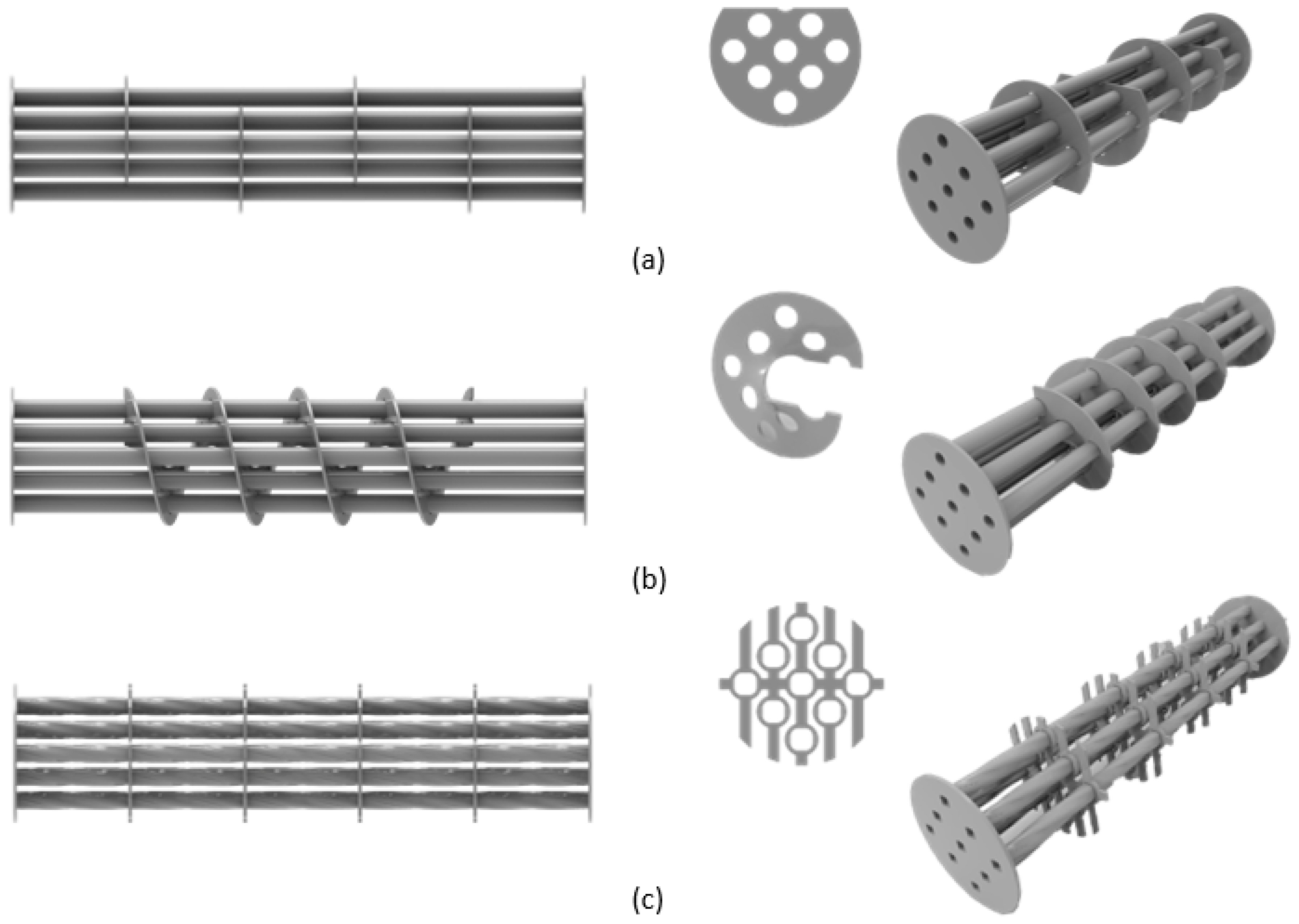
The standard type of baffles used is “segmental baffles”, which have a circle with a cut area called a baffle cut, as shown in Figure 1a, causing change in the direction of the flow as well as augmenting the fluctuation or variation in fluid flow in the shell-side fluid across the tubes. Thermal performance is amplified by enhancing turbulence and mixing in the fluid of the shell-side, resulting in loss of pressure in the shell-side, which demands high pumping power; owing to which, the energy consumption is multiplied [13]. However, there are some disadvantages in using conventional segmental baffles; the drawbacks of using segmental baffles are [14,15]: (1) pressure drop across the shell, (2) fouling resistance, (3) low efficiency in heat transfer for the reason of flow stagnation, and (4) the operation time of the STHXs is reduced due to the strong induced vibrations.
The use of baffles has utmost significance in performance of the heat exchangers. Diverse and many variations of different types of baffles have been incorporated to resolve problems such as to increase the heat transfer rates/pressure drop ratio in the shell-side fluid flow [9]. To enhance the thermohydraulic performance of the STHX, helical baffles are an alternative to conventional segmental baffles [16]. It can be seen in Figure 1b that the baffles are at an incline with helix angle ranging from 10 to 40 degrees, providing support to the tubes and making a helical flow pattern in the shell.
The benefits of helical baffles are less shell-side fouling, enhanced rate of heat transfer/pressure drop ratio in the shell-side, preventing flow induced vibrations, and less maintenance [17,18]. Our study emphasizes the use of continuous helical baffles because continuous helical baffles increase the heat transfer coefficient by 10% [19]. Though the majority of STHX use noncontinuous helical baffles; this is because of the inconvenience of manufacturing continuous helical baffles. Despite this, we are also familiar with the notion that noncontinuous helical baffles are subject to high fluid leakage ensuring drop in thermohydraulic performances contrasted with continuous helical baffles. [20,21].
Traditional STHXs using segmental baffles produce undesired vibrations due to the flow crossing the tube bundles vertically; whereas in helical baffles, the flow crosses the tube bundle at an angle relative to the axis, reducing induced vibrations [22]. These flow-induced vibrations in heat exchangers are the reason for failure of STHX, as many incidents have also been reported [23]. Acoustical resonance and flow-induced vibrations can cause critical damage to the system [24]. Researchers have been exploring ways to minimize these problems in heat exchangers and multiple solutions have been proposed to handle noise and vibration in heat exchangers. Reducing the shell-side flow rate, making a bypass in window area by removing the tubes, and reinstalling a new bundle are some of the methods to evade vibrations [25].
It is still an exigent demand to design and improve baffle structures for easy assembly and low pumping power consumption for energy perseverance. Although researchers have been successful in designing distinct and improved designs of baffles in STHX, these designs have been inadequate to meet the appropriate conditions for fouling, bundle vibration, heat transfer efficiency, assemblage, maintenance, and pumping power consumption. Eventually, this narrows the problem down to the conclusion that the current literature on shell-side flow structure has focused on the longitudinal, transverse, and helical flow patterns.
Clamping antivibration baffles with square twisted tubes as shown in Figure 1c is a new type of heat transfer device with no research as to evidence of their comparison with traditional baffles. They can effectively eliminate stagnant turbulent fluid flow zones and elude flow induced vibrations in contrast with the conventional STHXs involving segmental and helical baffle types by flowing the shell-side fluid longitudinally through the gaps in the baffles.
Amidst various experimental investigations, the thermohydraulic performance is considered to be accurate and potent. These experiments are expensive and time-consuming and it is not always practical to conduct experiments. Many researchers have conducted STHX studies based on CFD (Computational Fluid Dynamics) and secured convincing results. In this study, we will be implementing three different kinds of baffles to assess their effect on the thermohydraulic performance of STHX. Commercially proficient ANSYS FLUENT software was chosen to do numerical analysis on STHXs. The STHX parts: tubes, shells, baffles, and nozzles were built as CAD models for each scenario, i.e., using the segmental, helical, and clamping antivibration baffles.
The computational results were validated with data from traditional segmental baffles STHX. Then numerical model is used to calculate and compare the performance for the STHX with helical and clamping antivibration baffles. By using CFD analysis heat transfer characteristics and shell-side pressure drop were calculated. Two-way FSI analysis was used, in which the results of the CFD analysis are transferred to a mechanical model and the results of mechanical model are transferred back to the fluid model. This iterative process will continue until convergence is found or the process is stopped manually. By using this analysis shell side flow induced vibrations have been examined in this paper. Proper meshing strategy has been proposed for computing efficiency and meshing convenience. In this research there is a study of heat transfer rate, pressure drop, and control of the flow-induced vibrations.
2. Mathematical Modeling
2.1. CAD Models of the Three Types of Heat Exchangers
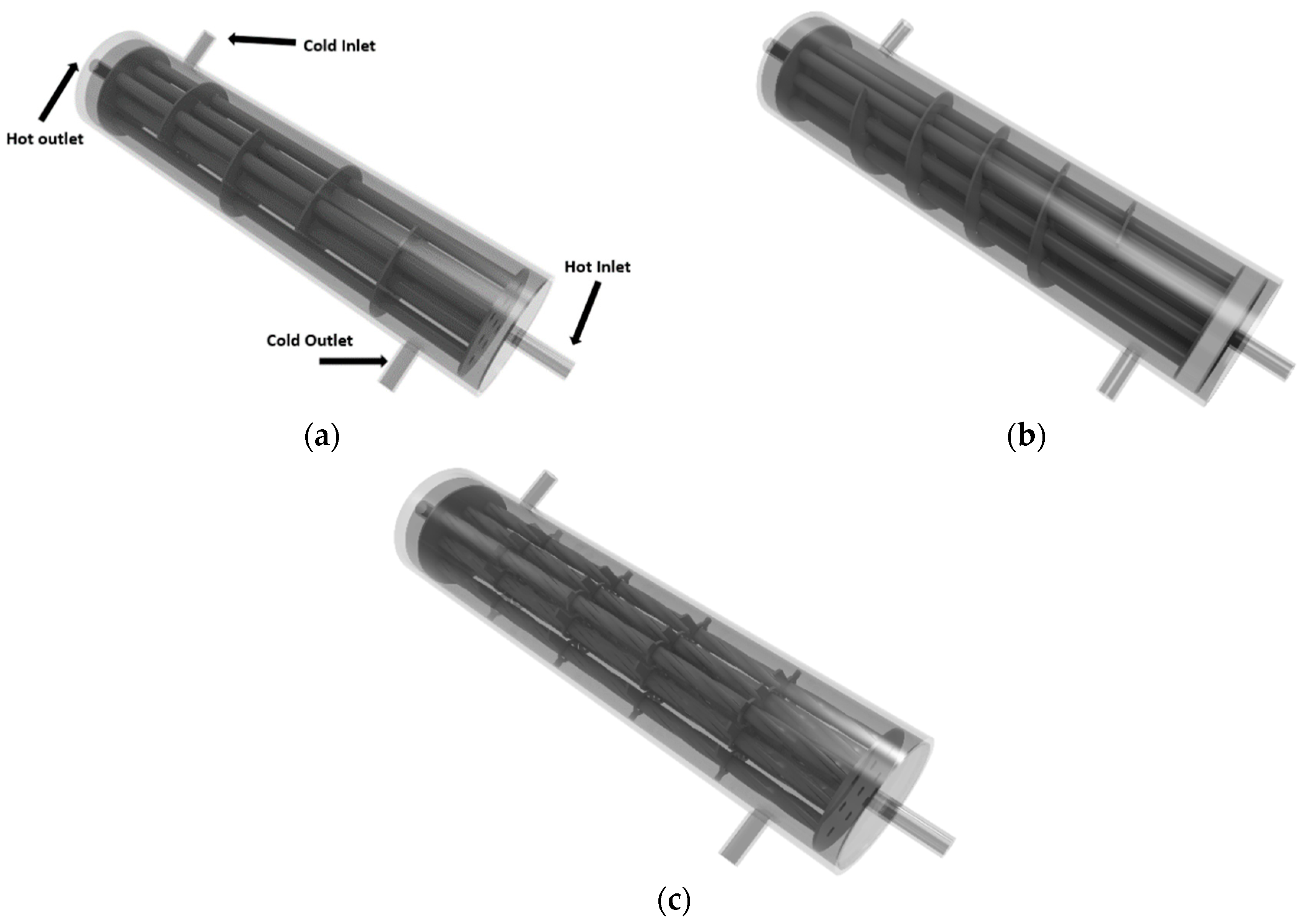
Figure 2 represents the configurations of the STHXs with segmental, helical, and clamping antivibration baffles. The size of the STHX model used in the study present is small; hence the modeling computational expense for various baffle types can be afforded.
The spacing of the baffles is retained the same in all the models to fortify the results for even comparison. Other than baffle type all the geometric parameters are kept consistent. With the same conditions and parameters, the comparison between the STHXs with three different baffles is more accurate [26]. Stainless steel with a thermal conductivity of = 15.2 W/(m K) was chosen as a material for different parts of STHXs. There is one solid domain (baffles and tubes) and two fluid domains (cold water in shell and hot water in tubes), for each computational domain. The fluid in both the shell-side and tube-side is in a counter current configuration. The shell has an external diameter: 50 mm; thickness: 3 mm; and length: 200 mm. More details are listed in Table 1.
2.2. Two-Way Fluid–Structure Interaction (FSI)
Vortex-induced vibration (VIV) is a phenomenon in which the structure and the flow field for the fluid are appraised to have direct effects on one another on aspects of being time-dependent. This problem is considered as a fluid structure interaction (FSI) type. We developed a combined fluid-structure, employing a two-way algorithm model using ANSYS Mechanical and FLUENT finite volume solvers. The algorithm is to focus on solving the fluid equations and the transfer of the hydrodynamic loads as an input loads to the mechanical model on the tubes, in each time step. Simultaneously, the tubes movement fed back into the fluid is calculated and the structural dynamic equations are solved. The diffusion equation used to compute the fluid mesh displacement and regularize motion of the dynamic grid [27]:
The above Equation (1) describes the diffusion of the boundary motion in the deforming mesh’s interior, stating that the differential operator ∇ is operated on the mesh displacement velocity and the diffusion coefficient . As per theory, the diffusion of boundary motion is uniform along the grid’s domain for constant , whilst there is a combined motion of high diffusivity nodes for nonuniform coefficient. For this study, nonuniform is adopted, as given by the following Equation (2).
in which is the area of element.
2.3. Subgrid Scale (SGS) and Turbulent Models
For the VIV problem, the different numerical approach methods used for simulation of the fluid field are mentioned as the Large-Eddy Simulation (LES), Direct Numerical Simulation (DNS), and the Reynolds-Averaged Navier-Stokes (RANS) [28]. However, DNS cannot approximate any data of the least energy dissipative scale type to the biggest kinetic energy types but can calculate directly using the Navier-Stokes equations, which have spatial and temporal properties as well. Because of such number of parameters, and the requirement of extremely fine 3-D modeled mesh for this method, the computational time is significantly high. However, to save the computational time and sources, the RANS approach is excluded of the turbulent fluctuations of the flow quantities. Thus, making this approach unsuitable for calculating the boundary layer transitions to turbulence.
The LES method, another method for the VIV problem, solves each scalar transport, momentum, and kinetic energy clearly, i.e., most of the turbulence motions of large-scale flow type. But the small-scale parameters are solved using a model known as the Subgrid Scale Model (SGS). Thus, the LES method got attention recently [29]. This proves that the LES method is more simplified and precise compared to RANS simulation method [30] and is also faster than the DNS approach in solving the VIV.
Varieties of SGS models have been proposed, e.g., the conventional algebraic Smagorinsky and the dynamic Smagorinsky–Lilly models, to get the full solution of LES [31]. Studies suggest that the dynamic Smagorinsky–Lilly model gives more accurate results in this approach. So, the dynamic Smagorinsky–Lilly model is used in this study.
2.4. Governing Equations
The STHX is presumed to have a minor shell-side fouling resistance, though it is ignored in the energy equation. We take water into account based on its characteristics of being a Newtonian and incompressible fluid. The fluid physical properties are constant and the effect of gravity is negligible. ANSYS is used to build hydrodynamic model based on the unstructured-grid finite volume method. The model is based on the solution of continuity, momentum, and energy equations [26,32]:
Continuity equation:
Momentum equation:
Energy equation:
where temperature, pressure, and fluid velocity are stated by T, p, and u, respectively. ν and Pr the fluid kinematic viscosity and Prandtl number, respectively, is the fluid density, and the subscript turb represents turbulent.
Earlier studies led the conclusion that the 2-D Navier-Stokes theory in solving/predicting the VIV turbulent flow does not give precise results. So to get precise results in the present study for the VIV responses, the combination of a dynamic Smagorinsky-Lilly SGS and the LES approach is suitable, to be solved with the incompressible Navier-Stokes equations, in a detailed model of turbulent flow in 3-D on the shell-side around the tubes. Implementing , which is volume filter function of space dependent type, provides us with the refined momentum and continuity equations [31]:
the grid filter width Δ is calculated from the cubic root of grid cell volume and is given as . Scales smaller than this are modeled with SGS, where as those that are larger can be solved directly and included in the flow.
The resolved large-scale strain rate tensor is related to the SGS stress by considering Boussinesq’s type approximation and a turbulent eddy viscosity as follows.
here δij is the Kronecker delta, with the condition that: δij = 1 if i = j and δij = 0 when i ≠ j. This makes sure that normal stresses are considered isotropic. Also, the SGS viscosity highlights only small scales as contrast to RANS model that depicts all turbulent scales with the eddy viscosity. The SGS viscosity in the conventional Smagorinsky model is represented as follows [31].
where represents the Smagorinsky constant, normally varying from 0.065 to 0.2 and is the norm of the strain rate tensor.
2.5. Domain Details, Boundary Conditions, and Meshes
The study comprises modeling of three different shell and tube heat exchangers with different types of baffles. Therefore, it is required to construct three different computational domains to study each of them individually. For each computational domain, the work is done keeping in mind the two fluid domains (water in the shell-side and tube-side) and one solid domain, i.e., baffles and tubes bundle. The geometries are constructed in Space Claim prior to the meshing. Clearance was designed in between the tube-to-baffle-hole as per TEMA RCB-4.2; hence the clearance between the tube-to-baffle-hole is 0.4mm [33].
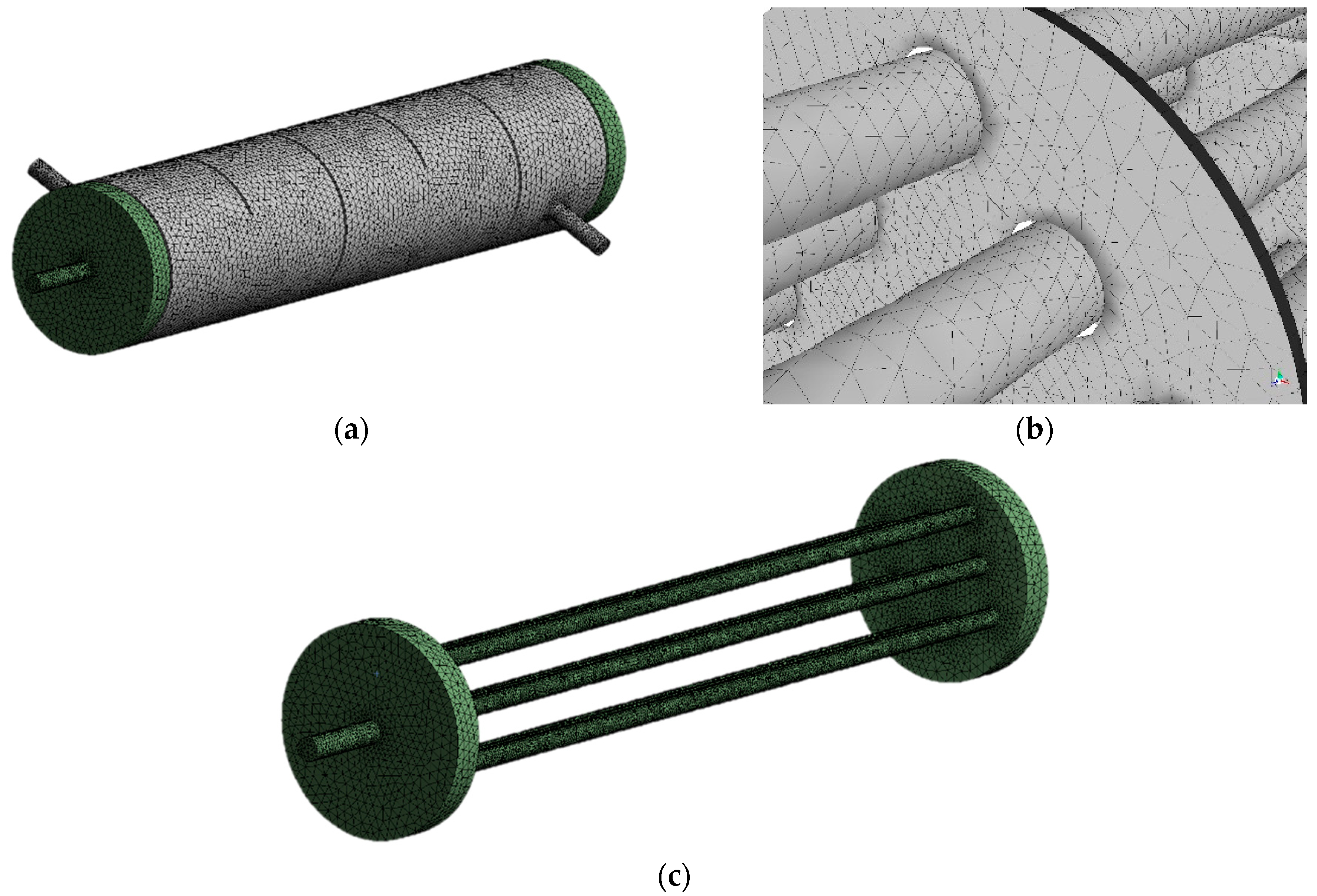
The ANSYS MESHING tool was utilized to mesh the fluid computational domain with unstructured tetrahedral grid. Built-in Mesh Metrics in ANSYS MESHING was employed to evaluate the quality of the mesh (skewness and elements quality) for each STHX Table 2. Fine cell sizing parameters are used to ensure good mesh around the narrow tubes and complicated baffle designs as shown in Figure 3.
The grid independency test is appraised to secure precision in the numerical results. To obtain the optimized computational mesh, many grid dependency tests were performed. In our study, we conducted multiple grid dependency trials, i.e., at 2.5 million, 3.9 million, and 4.5 million elements in the computation of the STHX-SGCT. The heat transfer rate observed between 3.9 million and 4.5 million is less than 2%. Consequently, the 3.9 million elements were endorsed for the grid system in the view for securing accuracy of solution and the time utilized for the convergence.
For the shell and tube side inlets the boundary conditions are set as velocity-inlet, and the outlets are applied as pressure-outlets. The pressure drop on both the tube and shell sides is equal to the inlet pressure because outlets are supposed to have zero pressure. All the solid walls are assumed to be nonslip boundary condition. There are five different inlet boundary conditions for each geometry design are performed at mass flow rate of 0.027 kg/s, 0.032 kg/s, 0.037 kg/s, 0.042 kg/s, and 0.047 kg/s. The shell wall is also assumed to have zero heat flux thermal boundary condition. The tube walls, baffles, and tube bundles are set to represent the solid-fluid interface to account for the heat transfer boundary condition.
The CFD simulation and two-way fluid-structure interaction (FSI) simulation were performed using ANSYS FLUENT and Mechanical software. The heat transfer process in between the fluid and solid structural tubes was computed. For FSI the clearance between the tube-to-baffle-hole is considered in the geometry
Fluid heat transfer calculations were achieved implementing finite volume methods by using the SIMPLE algorithm. The second-order upwind scheme is applied for the turbulence, energy, momentum, and dissipation rates. Default under relaxation factors of the solver are used, which are 0.3 for pressure, 0.7 for momentum, 0.8 for turbulent kinetic energy and turbulent energy dissipation. The standard scheme is applied to the pressure term.
3. Results and Discussion
3.1. Model Validation
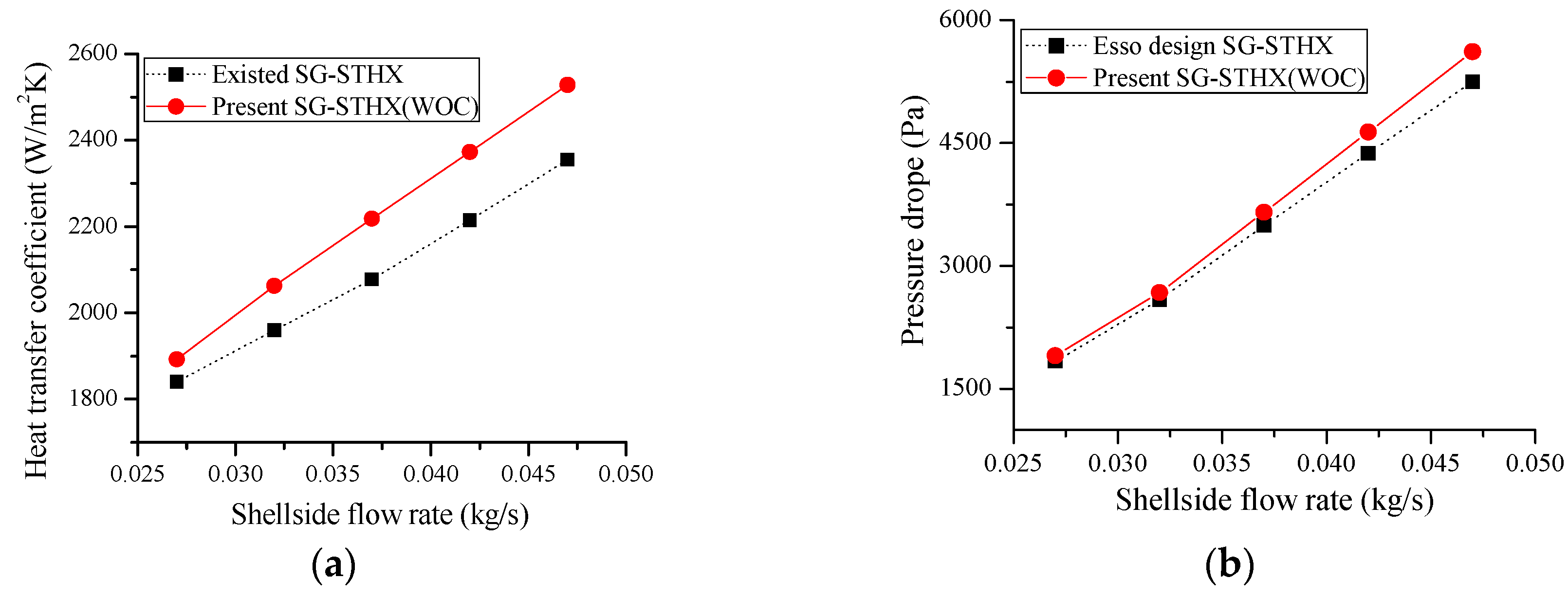
Already published results and the Esso method were used to validate the numerical model. To calculate the overall pressure drop Δp in the shell side of STHX with segmental baffles Esso method [33] is used, and for the overall shell side heat transfer coefficient existed results [34] are used. A comparison of the present results with the prediction of correlations is shown in Figure 4.
Present results show the better agreement with the already published results, deviation is found to be within 10%, and the average deviation of Esso design from the present results of pressure drop was also found to be less than 10%.
As far as the FSI results are concerned, there are three points.
- It was mentioned earlier that helical baffles flawlessly replaces segmental baffles hence maximizing the performance and by decreasing fluid-induced vibrations. It can be seen that the vortex shedding and deformation due to induced vibrations are more in STHX with segmented baffles than in STHX with helical baffles [22].
- Shell side fluid flow parallel to the tubes, propose much less pressure drop [35], and fluid-induced vibrations also reduce [36]. This is why the STHX with clamping antivibration baffles has minimum pressure drop and fluid-induced vibrations than other two heat exchangers because the shell side fluid flows longitudinal to the tubes in STHX with clamping antivibration baffles.
- In STHX the vibration of the tubes increases pressure drop [37]. It is evident that the STHX with clamping antivibration baffles has minimum pressure drop compared to the other two heat exchangers. Hence, the induced vibrations are less in STHX with clamping antivibration baffles.
3.2. Thermohydraulic Performances
Newton’s cooling law is used to compute the heat transfer coefficients on both tube and shell side. Heat transfer coefficient per unit pressure drop states the total thermohydraulic performance, i.e., the shell and tube side outlets of STHX are supposed to have zero pressure, hence, the pressure drop is equal to the inlets pressure for both tube and shell side.
3.3. Attributes of Flow Field
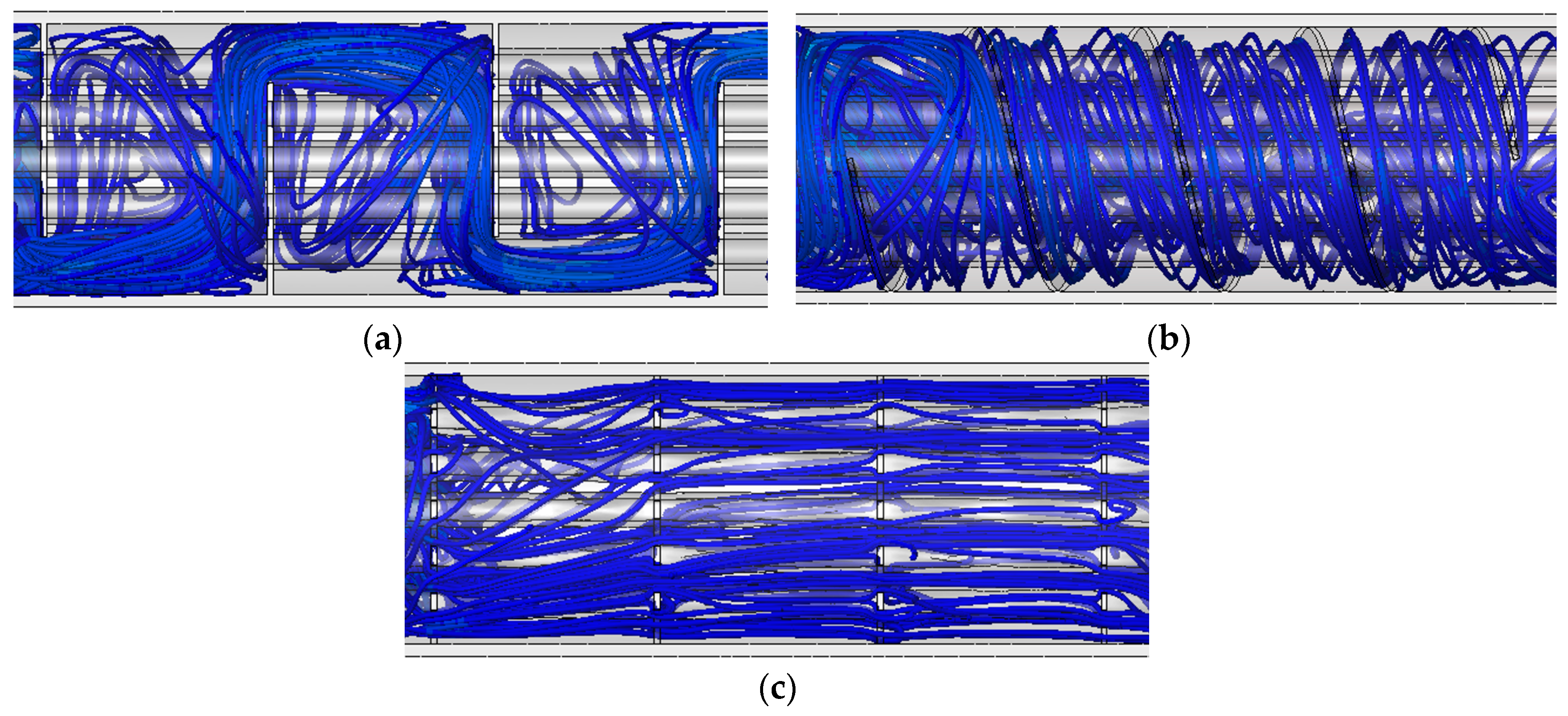
Baffle type defines the behavior of flow in the shell-side of shell and tube heat exchanger. Figure 5 depicts the streamline to show the attributes of flow in the shell side of STHXs with different baffle designs.
The zigzag flow pattern, as shown in the Figure 5a, for traditional segmental baffle causes large dead zones developed by large scale eddies. As a result, recirculation of fluid occurs at the back of the baffles. It causes a large amount of pressure drop in achieving sufficient heat transfer. It can be seen in Figure 5b with helical baffles the rotational flow pattern is achieved in the shell side of STHX. The shell side fluid rotates around the tubes, makes it perfect helical pattern. As fluid flow is moving without any disturbance there are very little dead zones near the baffles. This helical pattern offers a good mixing effect and therefore less pressure drop and greater heat transfer is attained compared to conventional segmental baffles.
The flow behavior of clamping antivibration baffle is also shown in Figure 5c, it can be seen that the streamlines are aligned in parallel to the tube bundle direction. Such parallel alignment increases the contact between hot fluid and cold fluid and is therefore expected to increase heat transfer performance and reduce pressure drop at the same flow rate.
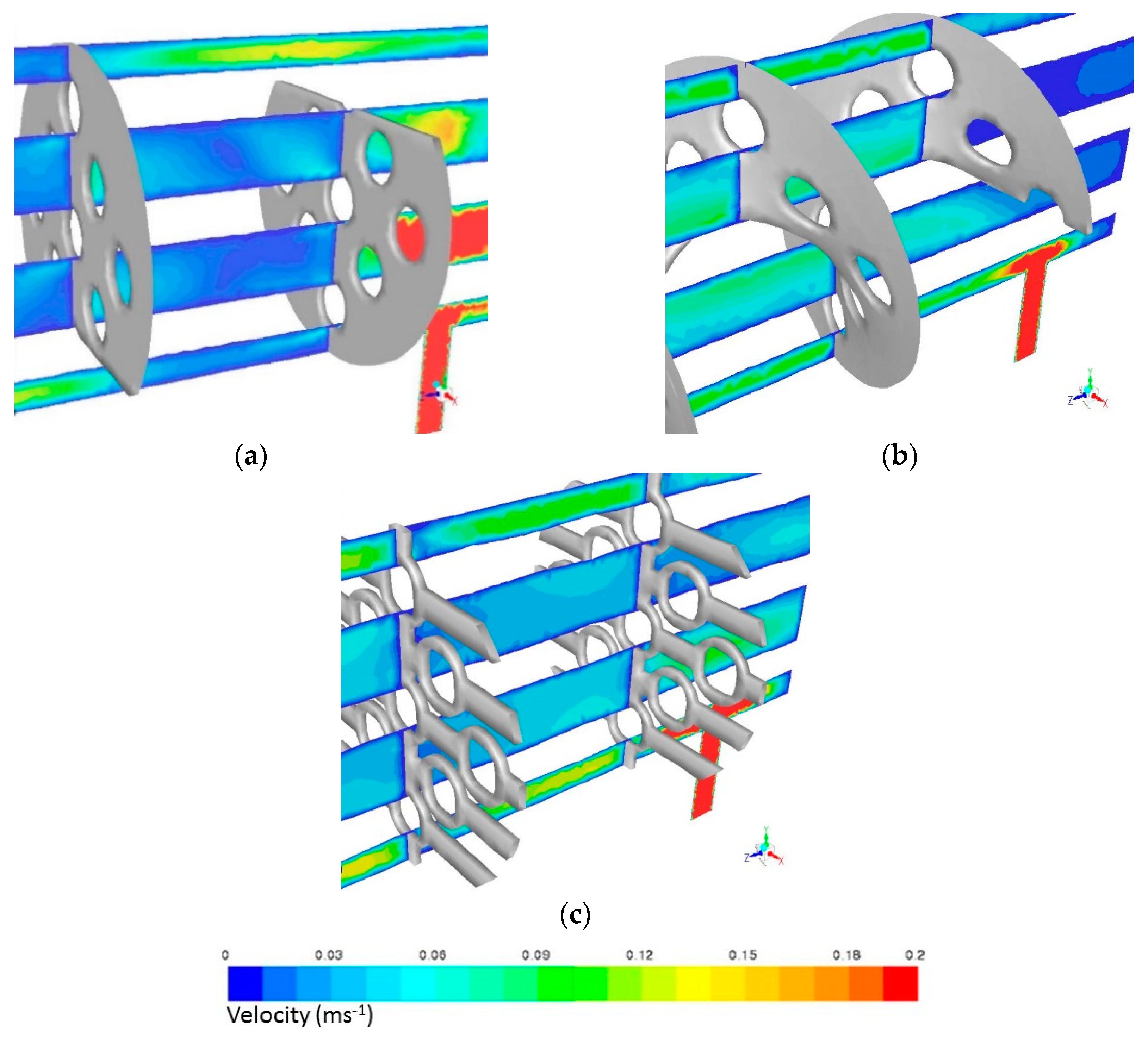
3.4. Pressure Drop
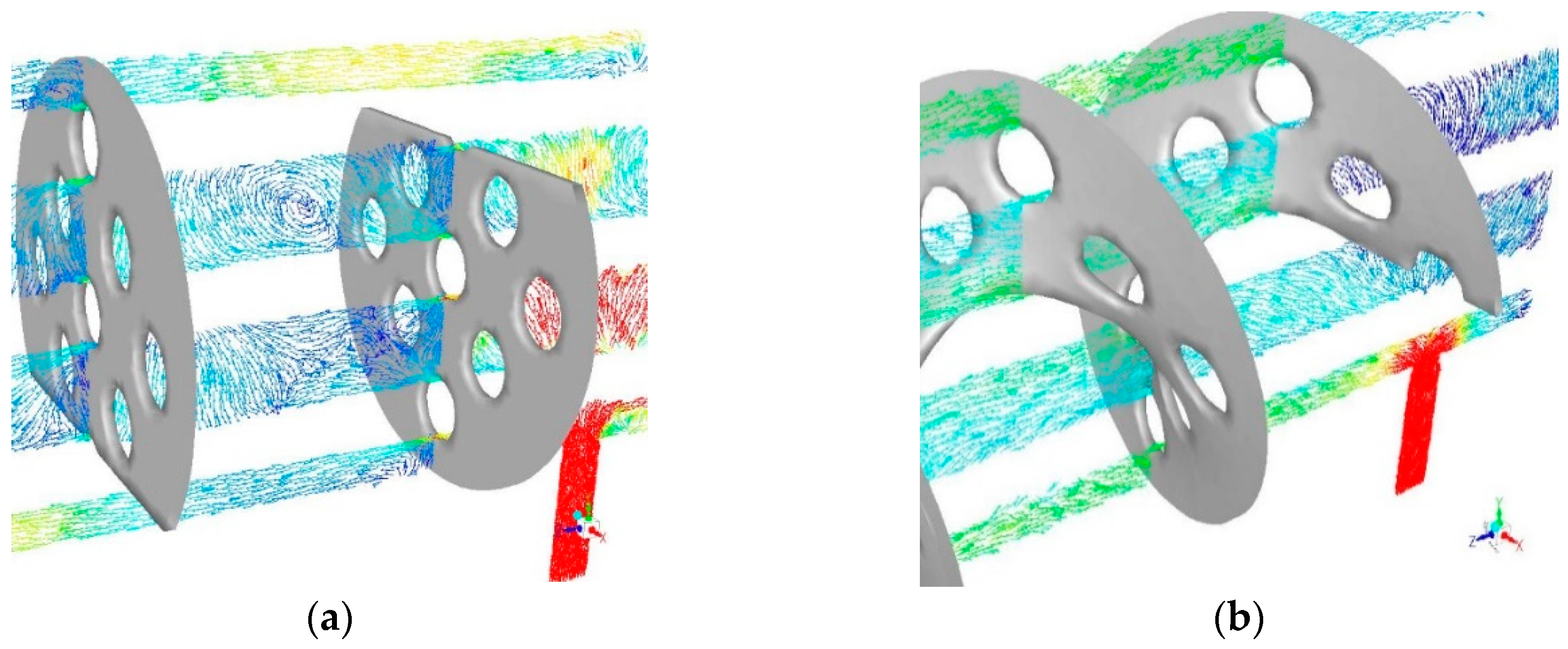
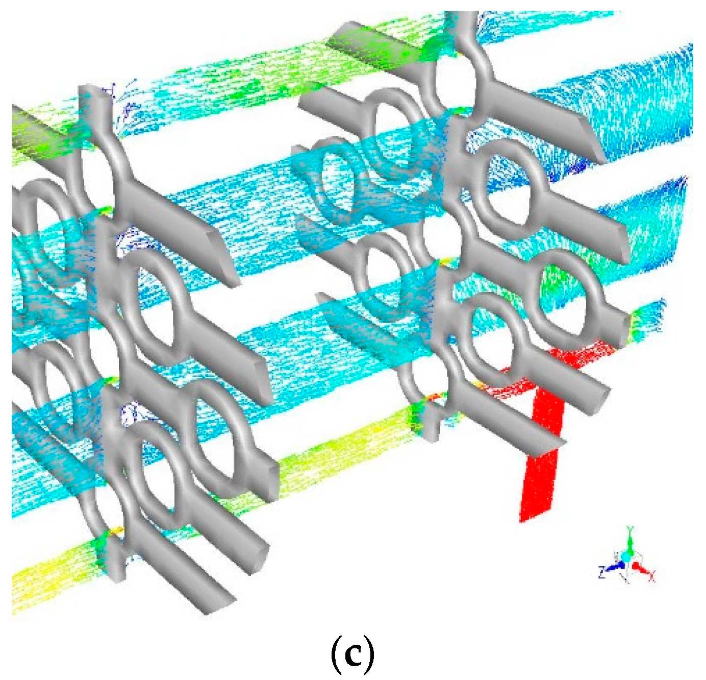
A smaller pressure drop results in a lower operating cost because pumping cost is highly linked with pressure drop. That is why in the design of STHX the pressure drop is of prime importance. Velocity distribution can be seen in Figure 6 at the shell side centerline plane for all of the three STHX configurations. The shell side maximum velocities are lower in helical and clamping antivibration baffles as compared to segmental baffles. Clamping antivibration baffles have the lowest shell side maximum velocities, located at the gaps between baffles and tubes. By comparison to clamping antivibration baffles, segmental and helical baffles produce greater shell side maximum velocities. It depicts that the pressure drop in clamping antivibration baffles is less as compared to the other two designs. Figure 7a depicts that the dead zones with lot of recirculation zones are created by segmental baffles. It can be seen in Figure 7c that the clamping antivibration baffle has better flow circulation, without dead zones. Pressure drop is increased due to dead zones, fluid recirculation and higher maximal velocities.
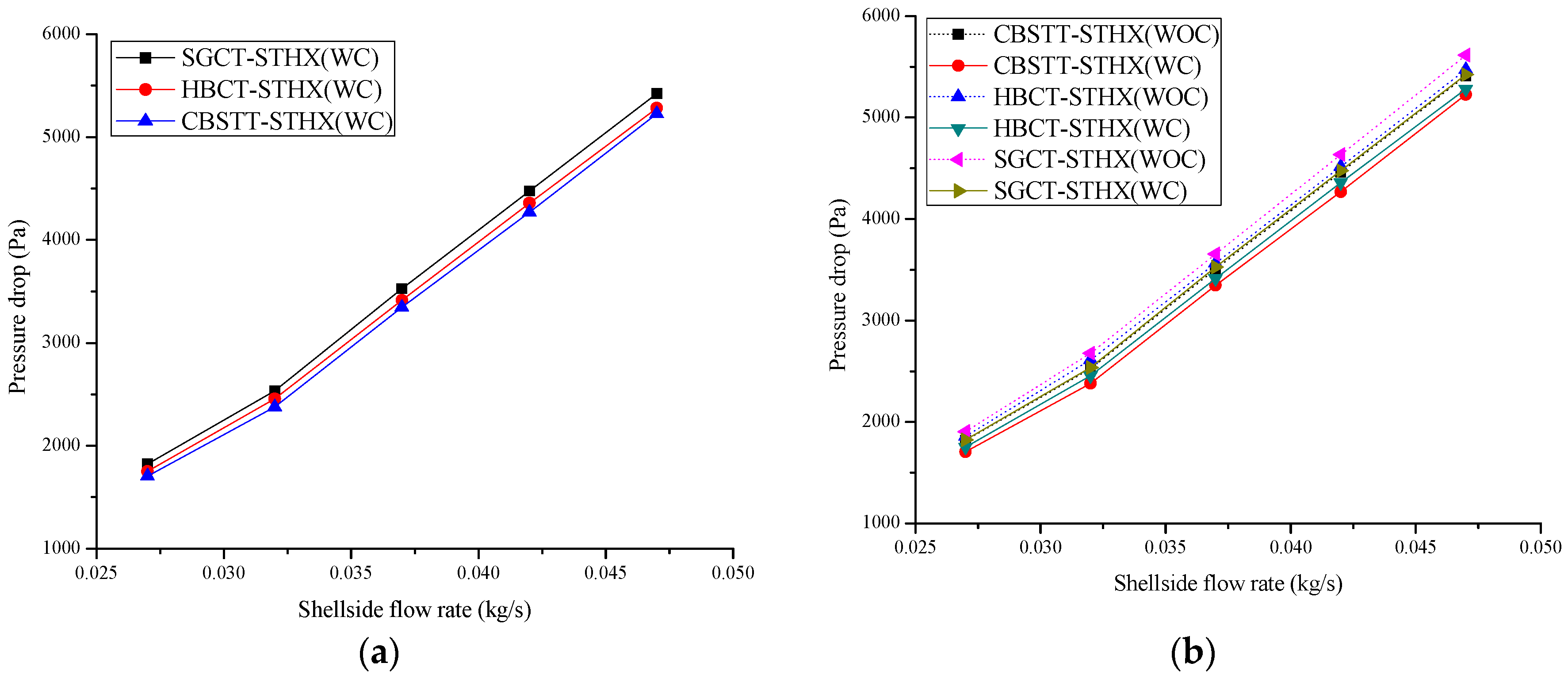
According to the analysis pressure drop will go from lowest to highest in the following order; clamping antivibration, helical, and segmental baffles. The change in pressure drop versus the shell side mass flow rate can be seen in Figure 8a for the three heat exchangers with tube-to-baffle-hole clearance.
For all three heat exchangers the pressure drop increases relative to the mass flow rate. As we discussed previously that the clamping antivibration baffles produce the lowest pressure drop compared to STHXs with segmental and helical baffles. The flow distribution in the shell side with segmental baffles is zigzag, causing sudden change in momentum and large pressure drop. While the flow direction of clamping antivibration baffles does not change intensely, causing less pressure drop.
It is evident in Figure 8b that the results of STHXs with tube-to-baffle-hole clearance show the reduction in pressure drop as compared to the STHXs without tube-to-baffle-hole clearance. STHXs with tube-to-baffle-hole clearance have less pressure drop because they allow the shell side fluid to pass easily and without resistance from the clearance. However, this clearance, after a certain limit, causes a negative effect and increases induced vibrations. That is why the CAD is designed according to the TEMA RCB-4.2.
3.5. Heat Transfer Performance
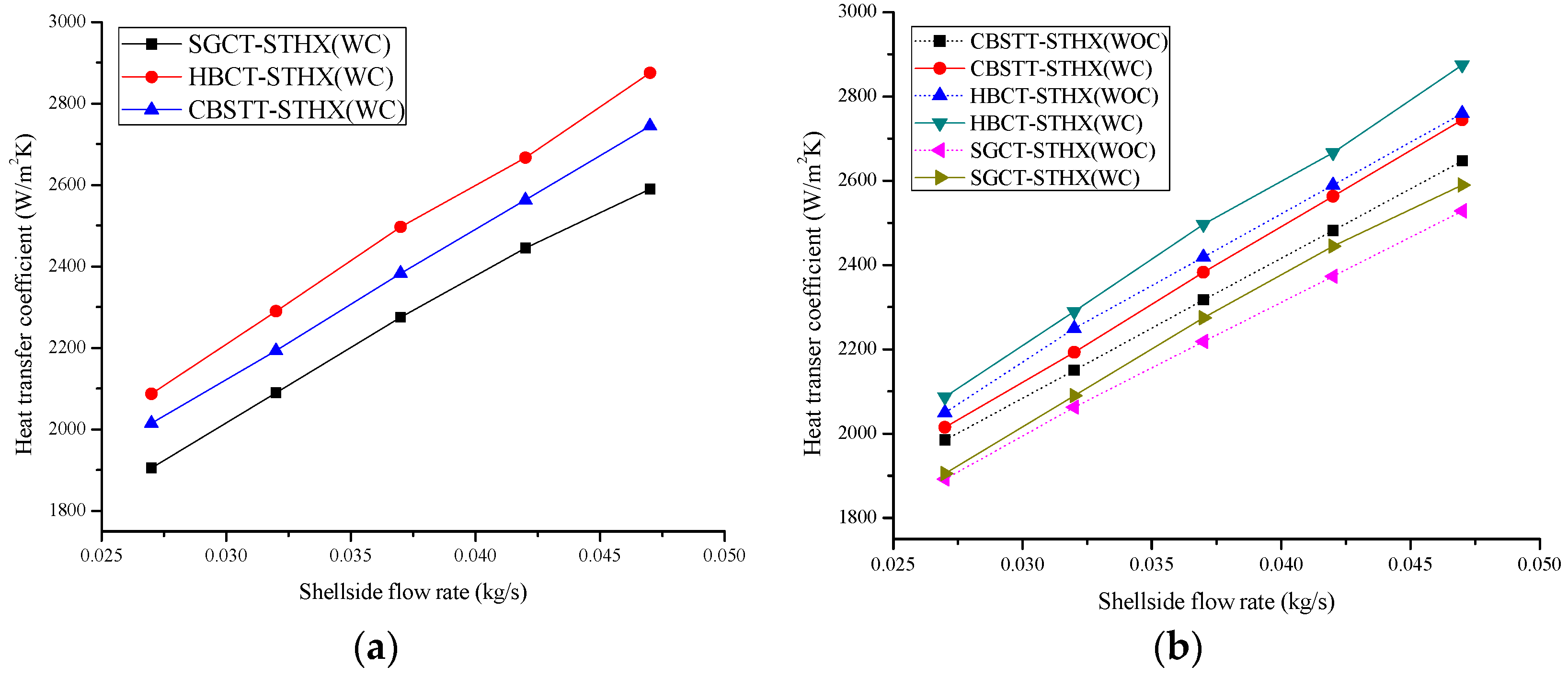
The evaluation of the shell side heat transfer coefficient for three STHXs with tube-to-baffle-hole clearance can be seen in Figure 9a. This figure also depicts that the shell side heat transfer coefficient is proportional to the mass flow rate. The heat transfer coefficient for STHX with helical baffles is greater than the STHXs with segmental and clamping antivibration baffles. SGCT-STHX presents a less heat transfer ability than other two types of STHXs.
Figure 9b shows that STHX with tube-to-baffle-hole clearance has greater heat transfer capacity compared to STHX without tube-to-baffle-hole clearance. This is because in the STHX with tube-to-baffle-hole clearance the shell side fluid and the tube have greater contact area for the transference of heat. As discussed earlier, the clearance must be according to the defined rules. If clearance increases a certain limit it causes decrease in heat transfer rate. As it reduces the turbulence in shell-side fluid and also increases flow induced vibrations because tubes get enough space to vibrate easily in baffle holes.
3.6. Vortex-Induced Vibrations (VIV)
The fluid flow vortex shedding, turbulent buffeting, acoustics resonance mechanism, and fluid elastic instability are the main causes of vibrations in the heat exchangers. Finite element method approach is modeled for the tube bundles to identify the vibration modes and natural frequencies of the tubes.
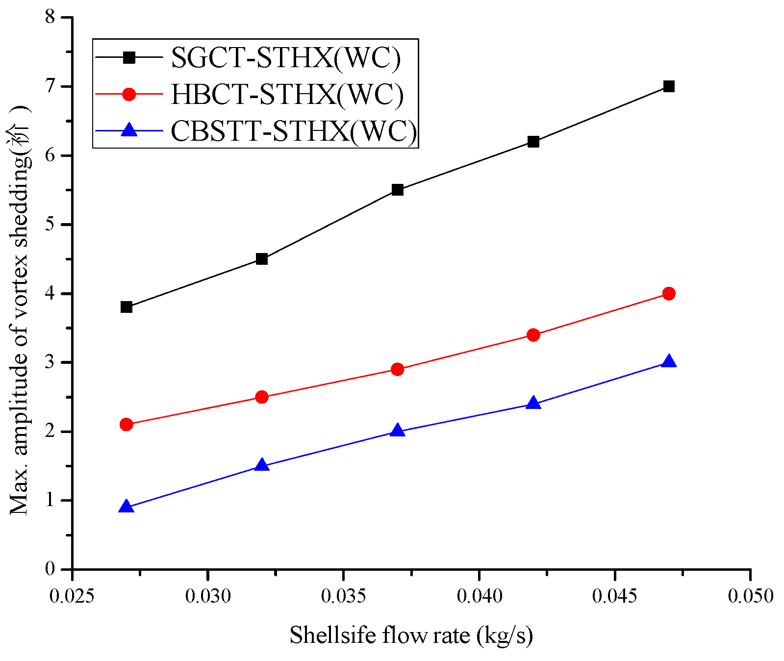
Vortex shedding leads to flow induced vibrations and failure. When a fluid stream flows over a body under certain operational conditions, the wake behind the mentioned body produces vortices, this vortex shedding produces lift and drag forces in the surface of the body with a certain excitation frequency. This phenomenon excites vibrations [38,39]. This may lead to unscheduled maintenance and possible performance penalties. A MATLAB code has been developed to perform a Fast Fourier Transform (FFT) analysis to find the maximum amplitude of the vortex shedding on five different mass flow rates. Figure 10 shows the comparison of vortex shedding amplitude versus mass flow rates of three different design configurations. Various fluid flow rate conditions have been studied for this comparison to understand the flow induced vibrations for these designs. It is seen that the STHX with clamping antivibration baffles has minimum amplitude of vortex shedding compared to the other two designs. It also shows that in STHX with clamping antivibration baffles, induced vibrations are less because of less vortex shedding. STHX with conventional segmental baffles has maximum amplitude of vortex shedding leading to maximum induced vibrations compared to other two designs.
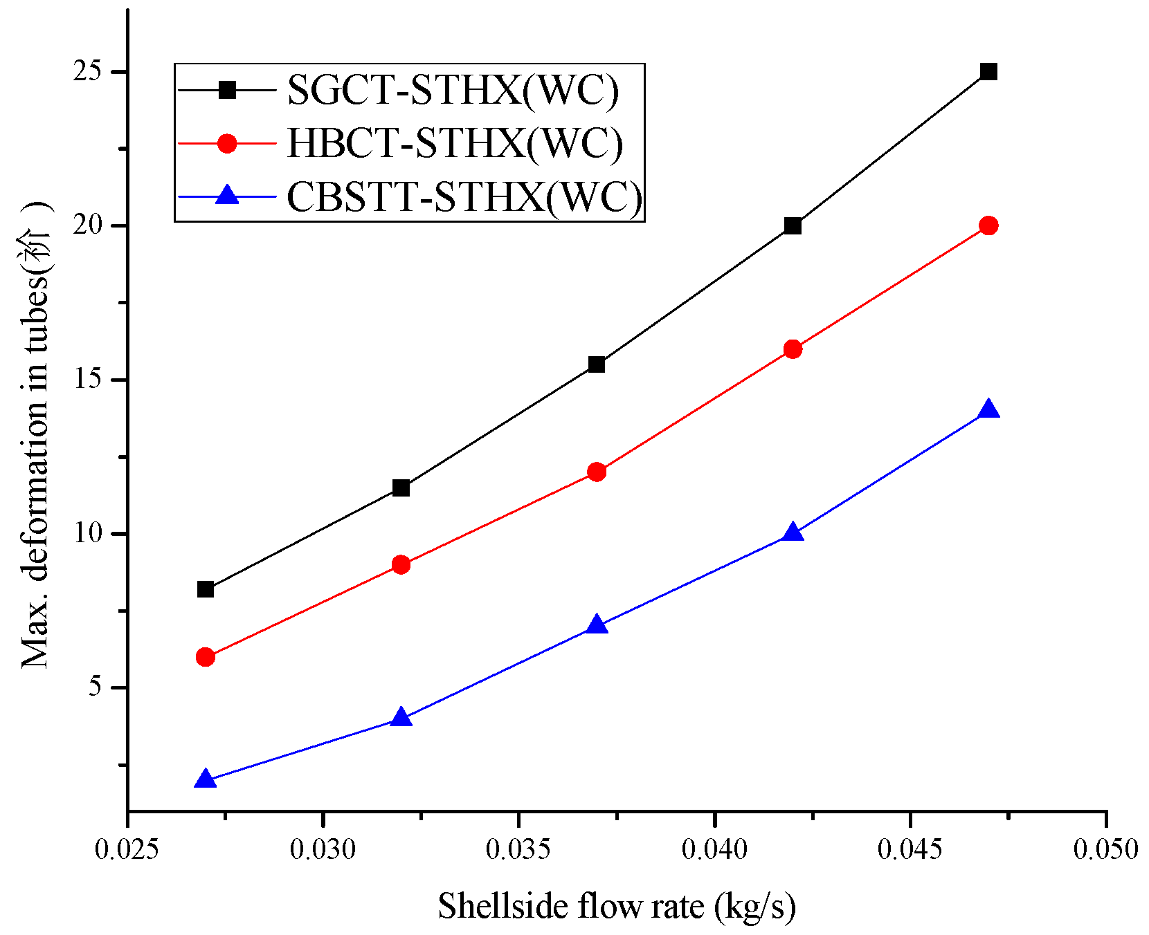
3.7. Maximum Tube Deformation
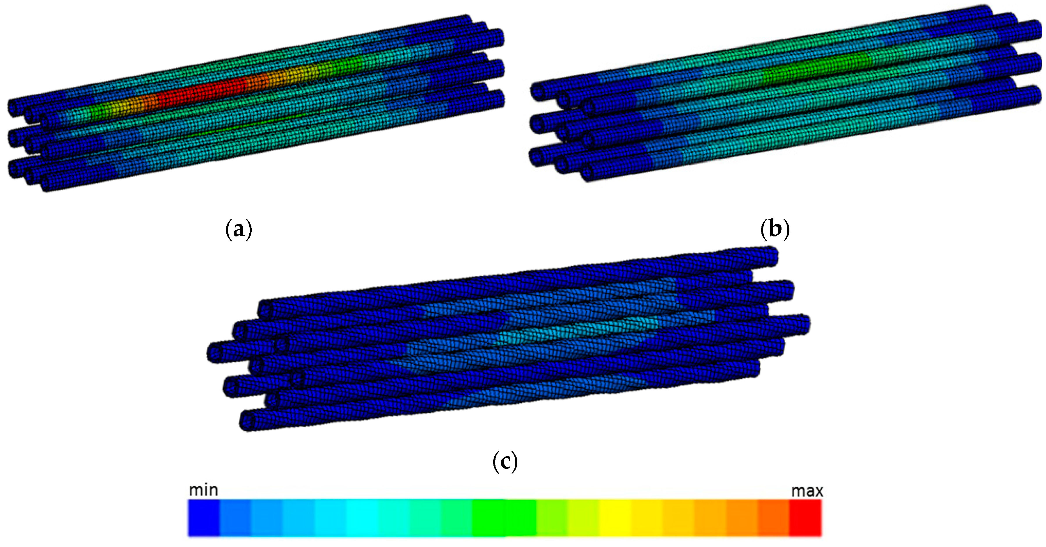
Figure 11 depicts the maximum tube deformation in three shell and tube heat exchangers. Figure 11a shows that STHX with segmental baffles has greater tubes deformation than two other STHXs.
As the segmented baffle design the total shell-side fluid, other than bypass streams and leakages, passes through the tubes between baffles in cross-flow, it causes maximum induced vibrations. Vortex shedding is also maximum in this design which causes greater deformation in tubes than other two STHXs. As already discussed, the STHX with clamping antivibration baffles the fluid flows in parallel direction to the tubes, so it induces minimum vibrations and causes minimum deformation in the tubes as shown in Figure 11c. Figure 12 represents maximum deformation in tubes versus mass flow rate, and shows that maximum deformation increases as mass flow rate increases. It also shows that the CBSTT-STHX has minimum tube deformation compared to the other two STHXs with segmental and helical baffles.
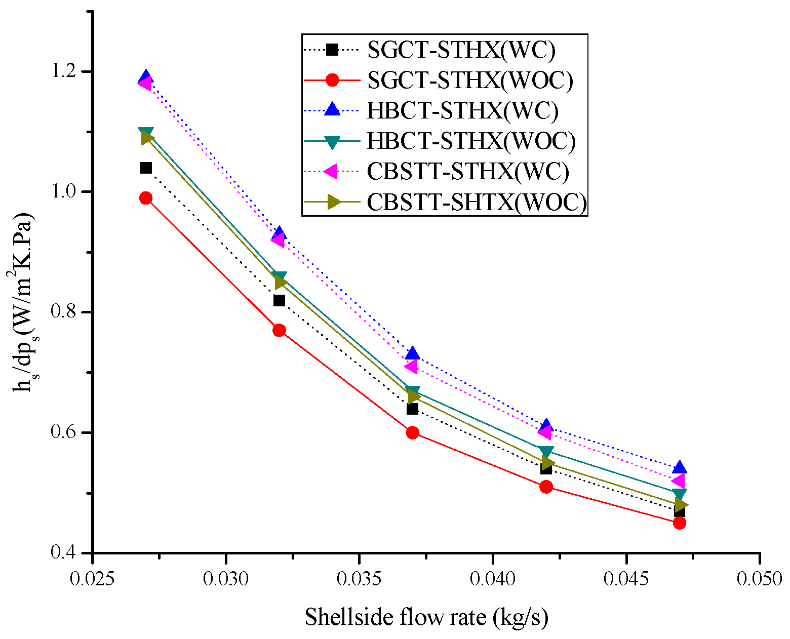
3.8. Comprehensive Performance Analysis ()
Considering both the pressure drop and heat transfer coefficient of the HXs are important to show the efficiency of HXs. These two factors are greatly dependent on each other. It is essential to increase the fluid velocities for better heat transfer coefficient but this also causes an increase in pressure drop. To improve the comprehensive performance, it is necessary to attain the higher heat transfer rate at the similar pressure drop. In the current study, the overall performance of the three STHXs is calculated by using the heat transfer coefficient per pressure drop.
Figure 13 illustrates the heat transfer coefficient per pressure drop versus shell-side mass flow rate for the three STHXs with tube-to-baffle-hole clearance and without tube-to-baffle-hole clearance. It can be seen that with the increase in shell-side mass flow rate, the heat transfer coefficient per pressure drop decreases for all HXs. It can be noticed that the overall thermohydraulic performance of STHX with CBSTT is higher than the STHX with SGCT. It can be concluded that the overall performance of both HBCT-STHX and CBSTT-STHX exhibits clear benefits compared to STHX with SGCT. The heat transfer rate of the new STHX with CBSTT is higher than the conventional STHX with SGCT at the same pressure drop. This is because the clamping antivibration baffles decrease the dead zones on the shell-side and smooth the fluid flow, hence causing the heat transfer enhancement. On other hand, the shell-side fluid flow direction in CBSTT-STHX does not change drastically that lessens the sudden change in momentum and pressure drop. Figure 13 also shows that the STHXs with a tube-to-baffle-hole clearance of 0.4 mm have greater performance than the STHXs without tube-to-baffle-hole clearance. This is because the clearance in the tube-to-baffle-hole increases heat transfer rate and reduces pressure drop.
4. Conclusions
This work comprises of a numerical model to evaluate and relate the use of different kinds of baffles and tubes to monitor the thermohydraulic performances and Fluid-induced vibrations of STHXs. The study is based on three different types of baffles and two different types of tubes: SGCT; HBCT; and CBSTT. Flow analysis attained by the flow equation proves that STHX with CBSTT is better than SGCT-STHX because of the pace at which the fluid flows and the constant and consistent distribution producing fewer dead zones and a reduced area inside the shell for fluid recirculation. Findings from the model show that helical baffles have the highest thermohydraulic performance outcome. Clamping antivibration baffles with square twisted tubes decrease the pressure drop compared to the other two heat exchangers and increase the heat transfer rate when compared to SGCT-STHX. It can be seen from the results that the STHXs with tube-to-baffle-hole clearance have higher heat transfer rate and reduction in pressure drop as compared to the STHXs without tube-to-baffle-hole clearance. It is because in the STHX with tube-to-baffle-hole clearance the shell side fluid and the tube have greater contact area for the transference of heat and they allow the shell side fluid to pass easily and without resistance from the clearance. We also conclude that the shell side fluid crosses the tubes vertically in SGCT-STHX which induces vibration in the tubes. However, in STHX with HBCT the fluid flow crosses the tube bundle at a certain angle relative to the axis and can reduce the induced vibration significantly. In CBSTT-STHX the shell side fluid flows longitudinally through the gaps in baffles; they eliminate stagnant recirculation zones and avoid flow induced vibration compared to the conventional STHXs with segmental and helical baffles. Tube deformation and vortex shedding is less in CBSTT-STHX than the other two types of shell and tube heat exchangers. Heat transfer augmentation and pressure drop reduction is minimal in the STHXs on two counts.
- The heat exchanger models used are small hence we can tolerate the modeling computational expense for the three baffle types and mass flow rate is also small to calculate the thermohydraulic performance. The changes in heat transfer rate and pressure drop will become much higher when industrial size heat exchangers with large mass flow rates are taken into consideration.
- Three things are taken into consideration simultaneously: heat transfer rate, pressure drop, and fluid-induced vibration. It is cumbersome to design a heat exchanger that is best in all aspects, so the pressure drop reduction and heat transfer enhancement rate are marginal but the thermohydraulic performance of novel baffle design is comparatively better than the conventional segmented baffles.
Author Contributions
S.M.A.N. performed the numerical simulation and wrote the paper. Q.W. supervised the work and revised the paper. All authors contributed to this work.
Acknowledgments
We would like to acknowledge financial support for this work provided by the Foundation for Innovative Research Groups of the National Natural Science Foundation of China (No.51721004) and the 111 Project (B16038).
Conflicts of Interest
The authors declare no conflict of interest.
Nomenclature
| Latin Symbols | |
| Across | cross-flow area at the shell centerline, mm2 |
| Ao | heat exchange area based on the external diameter of tube, mm2 |
| B | baffle spacing, mm |
| cp | specific heat capacity, J/(kg K) |
| ci | coefficients in k - ε model |
| Ds | internal shell diameter, mm |
| Do | external tube diameter, mm |
| h | average heat transfer coefficient, W/(m2 K) |
| k | turbulent fluctuation kinetic energy, m2/s2 |
| L | tube total effective length, m |
| mass flow rate, kg/s | |
| nt | number of tubes |
| Pt | tube pitch, mm |
| Pr | Prandtl number |
| Δp | pressure drop, Pa |
| Qave | average heat transfer rate, W |
| Re | Reynolds number |
| Tin | inlet temperature, K |
| Tout | outlet temperature, K |
| ΔT | logarithmic mean temperature difference, K |
| u | average velocity, m/s |
| x, y, z | Cartesian coordinate |
| turbulent eddy viscosity | |
| Cs | Smagorinsky constant |
| strain rate tensor | |
| Greek Symbols | |
| Γ | generalized diffusion coefficient |
| ε | turbulent kinetic energy dissipation rate, m2/s |
| λ | thermal conductivity, W/(m K) |
| μ | dynamic viscosity, kg/(m s) |
| ν | kinematic viscosity, m2/s |
| ρ | density, kg/m3 |
| σk | Prandtl number for k |
| Δ | grid filter width |
| Subscripts | |
| in | inlet |
| out | outlet |
| s | shell side |
| t | tube side |
| turb | turbulent |
| Abbreviations | |
| STHX | shell and tube heat exchanger |
| SGCT | segmental baffles with cylindrical tubes |
| HBCT | helical baffles with cylindrical tubes |
| CBSTT | clamping antivibration baffles with square twisted tubes |
| WOC | without tube to baffle hole clearance |
| WC | with tube to baffle hole clearance |
References
- Master, B.I.; Chunangad, K.S.; Boxma, A.J.; Kral, D.; Stehlík, P. Most frequently used heat exchangers from pioneering research to worldwide applications. Heat Transf. Eng. 2006, 27, 4–11. [Google Scholar] [CrossRef]
- Markowski, M.; Trafczynski, M.; Urbaniec, K. Identification of the influence of fouling on the heat recovery in a network of shell and tube heat exchangers. Appl. Energy 2013, 102, 755–764. [Google Scholar] [CrossRef]
- Yang, J.; Fan, A.W.; Liu, W.; Jacobi, A.M. Optimization of shell-and-tube heat exchangers conforming to TEMA standards with designs motivated by constructal theory. Energy Convers. Manag. 2014, 78, 468–476. [Google Scholar] [CrossRef]
- Pal, E.; Kumar, I.; Joshi, J.B.; Maheshwari, N.K. CFD simulations of shell-side flow in a shell-and-tube type heat exchanger with and without baffles. Chem. Eng. Sci. 2016, 143, 314–340. [Google Scholar] [CrossRef]
- Vukic, M.V.; Tomic, M.A.; Zivkovic, P.M.; Gradimir, S. Effect of segmental baffles on the shell-and-tube heat exchanger effectiveness. Hem. Ind. 2014, 68, 171e7. [Google Scholar] [CrossRef]
- Saffar-Avval, M.; Damangir, E. A general correlation for determining optimum baffle spacing for all types of shell and tube exchangers. Int. J. Heat Mass Transf. 1995, 38, 2501–2506. [Google Scholar] [CrossRef]
- Mukherjee, R. Effectively design shell-and-tube heat exchangers. Chem. Eng. Prog. 1998, 94, 21–37. [Google Scholar]
- Deng, X.H.; Den, S.J. Investigation of heat transfer enhancement of roughened tube bundles supported by ring or rod supports. Heat Transf. Eng. 1998, 19, 21–27. [Google Scholar]
- Stehlik, P.; Wadekar, V.V. Different Strategies to improve Industrial heat exchange. Heat Transf. Eng. 2002, 23, 36–48. [Google Scholar] [CrossRef]
- Bell, K.J. Heat exchanger design for the process industries. ASME J. Heat Transf. 2004, 126, 877–885. [Google Scholar] [CrossRef]
- Chen, Y.P.; Sheng, Y.J.; Dong, C.; Wu, J.F. Numerical simulation on flow field in circumferential overlap trisection helical baffle heat exchanger. Appl. Therm. Eng. 2013, 50, 1035–1043. [Google Scholar] [CrossRef]
- You, Y.H.; Chen, Y.Q.; Xie, M.Q.; Luo, X.B.; Jiao, L.; Huang, S.Y. Numerical simulation and performance improvement for a small size shell-and-tube heat exchanger with trefoil-hole baffles. Appl. Therm. Eng. 2015, 89, 220–228. [Google Scholar] [CrossRef]
- Kreith, F.; Manglik, R.M.; Bohn, M.S. Principles of Heat Transfer, 7th ed.; Cengage Learning: Boston, MA, USA, 2011. [Google Scholar]
- Wang, Q.; Chen, G.; Chen, Q.; Zeng, M. Review of improvements on shell-and tube heat exchangers with helical baffles. Heat Transf. Eng. 2010, 31, 836–853. [Google Scholar] [CrossRef]
- Li, H.; Kottke, V. Effect of the leakage on pressure drop and local heat transfer in shell-and-tube heat exchangers for staggered tube arrangement. Int. J. Heat Mass Transf. 1998, 41, 425–433. [Google Scholar] [CrossRef]
- Lei, Y.-G.; He, Y.-L.; Li, R.; Gao, Y.F. Effects of baffle inclination angle on flow and heat transfer of a heat exchanger with helical baffles. Chem. Eng. Process. 2008, 47, 2336–2345. [Google Scholar] [CrossRef]
- Stehlík, P.; Němčanský, J.; Kral, D.; Swanson, L.W. Comparison of correction factors for shell-and-tube heat exchangers with segmental or helical baffles. Heat Transf. Eng. 1994, 15, 55–65. [Google Scholar] [CrossRef]
- Kral, D.; Stehlik, P.; Van Der Ploeg, H.J.; Master, B.I. Helical baffles in shell-andtube heat exchangers, Part I: Experimental verification. Heat Transf. Eng. 1996, 17, 93–101. [Google Scholar]
- Peng, B.; Wang, Q.W.; Zhang, C.; Xie, G.N.; Luo, L.Q.; Chen, Q.Y.; Zeng, M. An experimental study of shell-and-tube heat exchangers with continuous helical baffles. J. Heat Transf. 2007, 129, 1425–1431. [Google Scholar] [CrossRef]
- Zhang, J.-F.; Li, B.; Huang, W.-J.; Lei, Y.-G.; He, Y.-L.; Tao, W.-Q. Experimental performance comparison of shell-side heat transfer for shell-and-tube heat exchangers with middle-overlapped helical baffles and segmental baffles. Chem. Eng. Sci. 2009, 64, 1643–1653. [Google Scholar] [CrossRef]
- Yang, J.-F.; Zeng, M.; Wang, Q.-W. Effects of sealing strips on shell-side flow and heat transfer performance of a heat exchanger with helical baffles. Appl. Therm. Eng. 2014, 64, 117–128. [Google Scholar] [CrossRef]
- Wang, Q.; Chen, Q. Numerical investigation on combined multiple shell-pass shell-and-tube heat exchanger with continuous helical baffles. J. Int. J. Heat Mass Transf. 2009, 52, 1214–1222. [Google Scholar] [CrossRef]
- Wootton, L.R. Industrial implications of flow induced vibrations. In Proceedings of the Institution of Mechanical Engineers, C 416/111, Brighton, UK, 20–22 May 1991; pp. 1–6. [Google Scholar]
- Gelbe, H.; Jahr, M.; Schrder, K. Flow-induced vibrations in heat exchanger tube bundles. Chem. Eng. Proc. 1995, 34, 289–298. [Google Scholar] [CrossRef]
- Goyder, H.G.D. Flow-induced vibration in heat exchangers. Chem. Eng. Res. Des. 2002, 80, 226–232. [Google Scholar] [CrossRef]
- Yang, J.-F.; Zeng, M.; Wang, Q.-W. Numerical investigation on combined single shell-pass shell-and-tube heat exchanger with two-layer continuous helical baffles. Int. J. Heat Mass Transf. 2015, 84, 103–113. [Google Scholar] [CrossRef]
- Zhao, M.; Cheng, L. Numerical simulation of two-degree-of-freedom vortex induced vibration of a circular cylinder close to a plane boundary. J. Fluids Struct. 2011, 27, 1097–1110. [Google Scholar] [CrossRef]
- Al-Jamal, H.; Dalton, C. Vortex induced vibrations using large eddy simulation at a moderate Reynolds number. J. Fluids Struct. 2004, 19, 73–92. [Google Scholar] [CrossRef]
- Zhiyin, Y. Large-eddy simulation: Past, present and the future. Chin. J. Aeronaut. 2015, 28, 11–24. [Google Scholar] [CrossRef] [Green Version]
- Catalano, P.; Wang, M.; Iaccarino, G.; Moin, P. Numerical simulation of the flow around a circular cylinder at high Reynolds numbers. Int. J. Heat Fluid Flow 2003, 24, 463–469. [Google Scholar] [CrossRef] [Green Version]
- Sagaut, P. Large Eddy Simulation for Incompressible Flows: An Introduction; Springer Science & Business Media: Berlin/Heidelberg, Germany, 2006. [Google Scholar]
- Fluent Inc. FLUENT User’s Guide; Fluent Inc.: Resource Park, Lebanon, 2006. [Google Scholar]
- Kuppan, T. Heat Exchangers Design Handbook; Marcel Dekker Inc.: New York, NY, USA, 2002. [Google Scholar]
- El Maakoul, A.; Laknizi, A.; Saadeddine, S.; El Metoui, M.; Zaite, A.; Meziane, M.; Abdellah, A.B. Numerical comparison of shell-side performance for shell and tube heat exchangers with trefoil-hole, helical and segmental baffles. Appl. Ther. Eng. 2016, 109, 175–185. [Google Scholar] [CrossRef]
- Lord, R.C.; Minton, P.E.; Sulusser, R.P. Design of exchangers. Chem. Eng. 1970, 96–118. [Google Scholar]
- Boyer, R.; Pase, G.K. The energy saving NESTS concept. Heat Transf. Eng. 1980, 2, 19–27. [Google Scholar] [CrossRef]
- Shokouhmand, H.; Sangtarash, F. The effect of flexible tube vibration on pressure drop and heat transfer in heat exchangers considering viscous dissipation effects. J. Heat Mass Transf. 2008, 44, 1435–1445. [Google Scholar] [CrossRef]
- Nikoo, H.M.; Bi, K.; Hao, H. Effectiveness of using pipe-in-pipe (PIP) concept to reduce vortex-induced vibrations (VIV): Three-dimensional two-way FSI analysis. Ocean Eng. 2018, 148, 263–276. [Google Scholar] [CrossRef]
- Di Domenico, N.; Groth, C. Fluid structure interaction analysis: Vortex shedding induced vibrations. Procedia Struct. Integr. 2018, 8, 422–432. [Google Scholar] [CrossRef]
Figure 1.
Model of tubes bundles with different baffles types: (a) segmental baffles; (b) helical baffles; and (c) clamping antivibration baffles.
Figure 1.
Model of tubes bundles with different baffles types: (a) segmental baffles; (b) helical baffles; and (c) clamping antivibration baffles.

Figure 2.
Isometric view of the computational domains for STHXs with: (a) segmental baffles; (b) helical baffles; and (c) clamping antivibration baffles.
Figure 2.
Isometric view of the computational domains for STHXs with: (a) segmental baffles; (b) helical baffles; and (c) clamping antivibration baffles.

Figure 3.
Mesh: (a) complete geometry; (b) baffle and tube; and (c) tubes.

Figure 4.
Model validation: (a) Comparison of the heat transfer coefficient of SGCT-STHX without tube-to-baffle-hole clearance with existed data and (b) comparison of the pressure drop of SGCT-STHX without tube-to-baffle-hole clearance with Esso design.
Figure 4.
Model validation: (a) Comparison of the heat transfer coefficient of SGCT-STHX without tube-to-baffle-hole clearance with existed data and (b) comparison of the pressure drop of SGCT-STHX without tube-to-baffle-hole clearance with Esso design.

Figure 5.
Shell path lines: (a) segmental baffles; (b) helical baffles; and (c) clamping antivibration baffles.
Figure 5.
Shell path lines: (a) segmental baffles; (b) helical baffles; and (c) clamping antivibration baffles.

Figure 6.
Velocity contours: (a) segmental baffles; (b) helical baffles; and (c) clamping antivibration baffles.
Figure 6.
Velocity contours: (a) segmental baffles; (b) helical baffles; and (c) clamping antivibration baffles.

Figure 7.
Velocity vectors: (a) segmental baffles; (b) helical baffles; and (c) clamping antivibration baffles.
Figure 7.
Velocity vectors: (a) segmental baffles; (b) helical baffles; and (c) clamping antivibration baffles.


Figure 8.
Pressure drop: (a) Shell side pressure drop versus mass flow rate and (b) pressure drop comparison of three STHXs, with and without tube-to-baffle-hole clearance.
Figure 8.
Pressure drop: (a) Shell side pressure drop versus mass flow rate and (b) pressure drop comparison of three STHXs, with and without tube-to-baffle-hole clearance.

Figure 9.
Heat transfer: (a) Shell side heat transfer coefficient versus mass flow rate and (b) heat transfer coefficient comparison of three STHXs, with and without tube-to-baffle-hole clearance.
Figure 9.
Heat transfer: (a) Shell side heat transfer coefficient versus mass flow rate and (b) heat transfer coefficient comparison of three STHXs, with and without tube-to-baffle-hole clearance.

Figure 10.
Maximum amplitude of vortex shedding versus mass flow rate.

Figure 11.
Maximum deformation in tubes at 0.027 kg/s: (a) SGCT-STHX; (b) HBCT-STHX; and (c) CBSTT-STHX.
Figure 11.
Maximum deformation in tubes at 0.027 kg/s: (a) SGCT-STHX; (b) HBCT-STHX; and (c) CBSTT-STHX.

Figure 12.
Max deformation in tubes versus mass flow rate.

Figure 13.
Heat transfer coefficient per pressure drop versus mass flow rate.


Table 1.
Structural parameters of the STHXs.
| Description | Numerical Value | Unit |
|---|---|---|
| Baffle-tube clearance | 0.4 | mm |
| Tube internal diameter | 4 | mm |
| Tubes number | 9 | - |
| Tube effective length | 186 | mm |
| Shell internal diameter | 44 | mm |
| Tube external diameter | 6 | mm |
| Number of Baffles | 4 | - |
| Baffle thickness | 1 | mm |
| Baffle spacing | 35.6 | mm |
| Baffle cut | 22% | - |
Table 2.
Mesh details.
| STHX Baffles Type | Nodes | Elements | Average Skewness | Average Element Quality | Average Orthogonal Quality |
|---|---|---|---|---|---|
| Segmental | 725,241 | 3,919,341 | 0.21173 | 0.82314 | 0.87445 |
| Helical | 729,574 | 3,938,738 | 0.21312 | 0.82174 | 0.87212 |
| Clamping | 746,784 | 3,957,572 | 0.21637 | 0.82531 | 0.87314 |
© 2019 by the authors. Licensee MDPI, Basel, Switzerland. This article is an open access article distributed under the terms and conditions of the Creative Commons Attribution (CC BY) license (http://creativecommons.org/licenses/by/4.0/).
Share and Cite
MDPI and ACS Style
Naqvi, S.M.A.; Wang, Q. Numerical Comparison of Thermohydraulic Performance and Fluid-Induced Vibrations for STHXs with Segmental, Helical, and Novel Clamping Antivibration Baffles. Energies 2019, 12, 540. https://doi.org/10.3390/en12030540
AMA Style
Naqvi SMA, Wang Q. Numerical Comparison of Thermohydraulic Performance and Fluid-Induced Vibrations for STHXs with Segmental, Helical, and Novel Clamping Antivibration Baffles. Energies. 2019; 12(3):540. https://doi.org/10.3390/en12030540
Chicago/Turabian StyleNaqvi, S.M.A., and Qiuwang Wang. 2019. "Numerical Comparison of Thermohydraulic Performance and Fluid-Induced Vibrations for STHXs with Segmental, Helical, and Novel Clamping Antivibration Baffles" Energies 12, no. 3: 540. https://doi.org/10.3390/en12030540
Note that from the first issue of 2016, this journal uses article numbers instead of page numbers. See further details here.