Article

An Improved UDE-Based Flux-Weakening Control Strategy for IPMSM

1
School of Electrical Engineering and Automation, Tiangong University, Tianjin 300387, China
2
School of Artificial Intelligence, Tiangong University, Tianjin 300387, China
*
Author to whom correspondence should be addressed.
Energies 2019, 12(21), 4077; https://doi.org/10.3390/en12214077
Submission received: 5 September 2019 / Revised: 23 October 2019 / Accepted: 25 October 2019 / Published: 25 October 2019
(This article belongs to the Special Issue Advances in Rotating Electric Machines)

Abstract

:
Interior permanent magnet synchronous motors (IPMSMs) are usually used in electric vehicle drives and in other applications. In order to enlarge the speed range of IPMSMs, the flux-weakening control method is adopted. The traditional flux-weakening control strategy degrades the control performance because of parameter mismatches caused by variation of motor parameters. An improved uncertainty and disturbance estimator (UDE)-based flux-weakening control strategy is proposed for IPMSM drives in this paper. The parameter tuning method in the UDE-based control is improved. In addition, a flux-weakening adjusting factor is put forward to reduce the torque fluctuation when the operation point switches between the constant torque region and the flux-weakening region. This factor can be adjusted online by a lookup table. Finally, the validity of proposed method is verified by the simulation and experimental results. The results show that the proposed control strategy can effectively enhance the robustness of the system in the flux-weakening region, and make the system switch more smoothly between the constant torque region and the flux-weakening region.

1. Introduction

Interior permanent magnet synchronous motors (IPMSMs) have been widely used in the electric vehicle (EV) drives due to their simple structure, wide speed range, high power, and torque density. IPMSMs often run above the rated speed in some applications, such as EVs, which is the maximum speed that the motor can obtain in the constant torque region. The flux-weakening control is usually adopted in an IPMSM system for acquiring higher speed and meeting the application demand. A negative d-axis current is injected to the stator windings in the flux-weakening control strategy. The air gap magnetic field of an IPMSM is reduced under the direct axis armature reaction caused by negative d-axis current. Then, the motor speed increases as the magnetic field reduction. The copper and iron losses of IPMSMs increase with an increase in speed, which results in the temperature rising. The parameters of IPMSMs, such as stator resistance and inductance, vary nonlinearity with the temperature rising. The control performance of the IPMSM system is degraded under uncertain parameter variation. Meanwhile, the torque fluctuation caused by switching between the constant torque region and the flux-weakening region bring adverse effects to the smoothness of IPMSMs.
An improved feedforward control strategy is proposed to reduce the impacts from parameter variation caused by flux-weakening control in [1,2,3,4]. The reference values of d-axis and q-axis currents are given by a lookup table. The parameter identification is adopted in flux-weakening control to enhance the systemic robustness in [5,6]. The parameters of the motor can be identified online using this method. The influence of magnetic saturation and stator resistance are considered in [7], and an optimal control strategy is proposed. However, the flux observation is limited by the rotor position in this strategy. A linearized and constrained model predictive control is put forward to the flux-weakening control in [8]. However, this method involves a large amount of calculation and is extremely sensitive to parameter variation. In order to suppress the influence of parameter variation on the system, a voltage feedback control strategy is applied in the flux-weakening region. A flux-weakening current output by a proportional integral (PI) controller is added to the d-axis current reference. The input of the PI controller is the difference between the output voltage amplitude and the maximum available voltage amplitude of inverter. This method is simple, independent of motor parameters, and has good robustness, but the dynamic performance needs to be improved. The conventional voltage feedback method is improved in [9]. The difference between DC link voltage and output voltage of current controller is used to calculate the phase angle of reference current space vector by an adaptive algorithm. However, the global stability of the IPMSM system cannot be guaranteed. A single current regulator is proposed to improve the voltage utilization of the DC bus in [10]. This method eliminates the poor effect caused by the coupling of the d and q axis current, but the decrease of efficiency and stability is still not to be ignored. A line modulation-based flux-weakening control was proposed to maximize the DC bus voltage utilization in [11].
The difference between the output voltage amplitude and the maximum voltage amplitude of the inverter is regarded as the judgment of whether to enter the flux-weakening region to reduce the switching fluctuation caused by different control algorithms in constant torque region and flux-weakening region in [2,8,12,13]. A variable coefficient is used to adjust the stator flux linkage which contributes to generating the maximum and most suitable torque and to achieve smooth switching [3]. The d-axis current reference is modified by comparing the switching period and summation of active switching times for inverter pulse width modulation control in the flux-weakening region, thus extending the hexagon of the space vector modulation in [14]. The smooth switching between the constant torque region and the flux-weakening region is realized by using the amplitude of inverter output voltage and d-axis current as input of set-reset flip-flop in [15].
Recently, an uncertainty and disturbance estimator (UDE)-based control has attracted much attention and has been applied to unknown time delay systems, nonlinear systems, and power converters [16,17,18,19,20,21,22]. The algorithm assumes that an unknown continuous signal can be estimated by an appropriate filter and compensated to the control system. It is helpful for solving the problem that the control performance deteriorates due to the parameter variations in flux-weakening control and has strong robustness. The UDE-based method is applied to the inverter for improving the output voltage quality of the inverter and reducing the total harmonic distortion in [16,17], and this method improves the stability of the system in nonaffine and nonlinear systems [18]. The UDE-based control is applied to surface permanent magnet synchronous motor and proposes a simple parameter tuning algorithm in [19], but does not analyze the operating condition in flux-weakening regions. The influence of different filters on the system has been discussed in detail [20]. The asymptotic tracking and disturbance suppression are realized under different types of reference values.
In this paper, an improved UDE-based flux-weakening control strategy for an IPMSM system is proposed to solve the poor robustness caused by parameter variation in the flux-weakening region, and the torque fluctuation when the operation point switches between the constant torque region and flux-weakening region. The motor model and flux-weakening control strategy are presented in Section 2. The UDE-based control is introduced and the parameter tuning method is improved in Section 3. The flux-weakening adjusting factor and its lookup table method are proposed in Section 4. The analysis of parameter mismatches is carried out in Section 5. The experimental validation of proposed method is carried out in Section 6. Finally, Section 7 comprises the summary.

2. Mode and Flux-Weakening Control Strategy

The model of an IPMSM in the synchronous rotating coordinate system is expressed as
u d = R s i d + L d d i d d t ω e L q i q ,
u q = R s i q + L q d i q d t + ω e L d i d + ω e ψ f ,
T e = 3 2 p [ ψ f i q + ( L d L q ) i d i q ] ,
where Rs, Ld, and Lq are the stator resistance, d-axis, and q-axis inductance, respectively; ψf is permanent magnet flux linkage; p is pole pairs; id and iq are d-axis and q-axis currents; ωe is the electric angular of rotor; and Te is the electromagnetic torque.
The maximum torque per ampere (MTPA) control strategy is often used in IPMSMs to achieve the optimal configuration of the given current when the IPMSM runs in the constant torque region. This strategy makes full use of the reluctance torque due to the difference between Ld and Lq. It can minimize the stator current at the same electromagnetic torque. In the MTPA, the d-axis current id*.MTPA is shown as
i d . MTPA * = ψ f 4 ( L q L d ) 2 ( i q * ) 2 ψ f 2 2 ( L q L d ) ,
where iq* stands for the q-axis current reference which is obtained by the output of the speed controller.
A valid operating point of the IPMSM is limited by the voltage and current constraints. Considering the influence of the stator resistance, the voltage and current constraints are shown as follows:
( L d i d + ψ f ) 2 + ( L q i q ) 2 ( U smax R s I smax ω e ) 2 ,
i d 2 + i q 2 I smax 2 ,
where Usmax and Ismax represent the maximum voltage and maximum current, and they are limited by the inverter and motor.
The reference voltage output obtained by the current controller can reach or exceed the maximum value of the inverter with the increase of motor speed. Thus, the MTPA control strategy cannot further improve the speed of the IPMSM. The flux-weakening control is usually adopted to solve this problem. The negative d-axis current is further increased in flux-weakening region. According to the Equations (5) and (6), the d-axis current i*d.FW in flux-weakening control is expressed as follows:
i d . FW * = ψ f + ( U smax R s I smax ω e ) 2 ( L q i q * ) 2 L d .
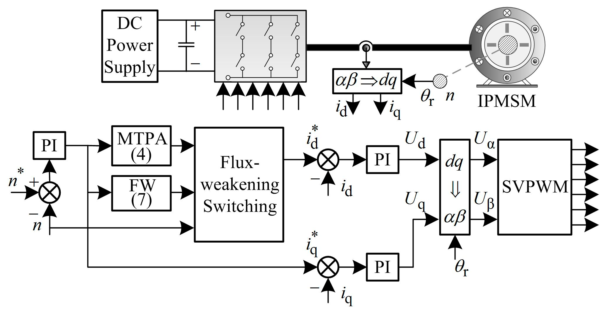
The MTPA control strategy is adopted when the motor is running in the constant torque region, and the motor is switched to flux-weakening control when the motor speed is higher than the maximum speed of the constant torque region. The traditional control strategy based on PI controller is shown in Figure 1.
It can be seen from Figure 1 that the d-axis current is calculated by formulas. The parameters of PI controller cannot match well with the variable motor parameter caused by flux weakening. This leads to the performance decline of the IPMSM system. In addition, the fluctuation caused by the switching between the constant torque region and flux-weakening region at a fixed speed is necessary to be solved.

3. The Design of UDE-Based Control

The uncertainty and disturbance are regarded as unknown signal in a UDE-based control system. A stable reference model is used to satisfy the desired tracking performance of the closed-loop system. Uncertainties and disturbances are compensated to the controller by using an appropriate filter. Thus, the control law of UDE-based control is obtained.
The motor parameter variations and systemic random disturbances are regarded as an unknown signal in the IPMSM control system. The current-loop model of UDE-based control under the synchronous rotating coordinate system is obtained as
d i d d t = R s L d i d + ω e L q L d i q + 1 L d u d + f d + D d ,
d i q d t = R s L q i q ω e L d L q i d + 1 L q u q 1 L q ω e ψ f + f q + D q ,
where Dd and Dq are the d-axis and q-axis systemic random disturbances; fd and fq are the d-axis and q-axis uncertainties caused by the variations of motor resistance, inductances, and flux linkage. The fd and fq are expressed as the average current ripple vector in sample period (0, Ts] and (Ts, 2Ts] are defined as follows:
{ f d = Δ R s L d i d Δ L d L d d i d d t + ω e Δ L q L d i q f q = Δ R s L q i q Δ L q L q d i q d t ω e Δ L d L q i d ω e Δ ψ f L q .
Equations (8) and (9) can be rewritten in matrix from as
x ˙ ( t ) = A x ( t ) + B u ( t ) + d 0 ( t ) + f ( t ) + D ( t ) ,
where x(t) = [id iq]T, u(t) = [ud uq]T, f(t) = [fd fq]T, D(t) = [Dd Dq]T,
d 0 ( t ) = [ 0 ω e ψ f L q ] , A = [ R s L d ω e L q L d ω e L d L q R s L q ] , B = [ 1 L d 0 0 1 L q ] .

3.1. The Reference Model

A stable reference model is used to achieve asymptotic tracking of the motor reference current in UDE-based control. The selection of reference model is related to control object. According to the structure of the IPMSM control system, the following linear reference model is adopted.
x ˙ m ( t ) = A m x m ( t ) + B m c ( t ) ,
where xm = [idm iqm]T is the d-axis and q-axis current reference state vector, c = [id* iq*]T is the d-axis and q-axis current reference command vector.
xm(t) and c(t) are the second-order matrices selected in the reference model for achieving the desired tracking performance of the control system. Due to the difference between the d-axis and q-axis inductances in IPMSMs, the coefficient matrix of reference model is given as
A m = [ α 0 0 β ] , B m = [ α 0 0 β ] ,
where α and β are two independent positive real numbers.
Based on the above reference model, the currents can asymptotically track the reference state vector of the d-axis and q-axis current by controlling the input voltage u(t) of the control system. The tracking error and dynamic error are expressed as
e ( t ) = x m ( t ) x ( t ) ,
e ˙ ( t ) = ( A m + K ) e ( t ) ,
where K is an error feedback gain matrix of the reference model which is used to guarantee the system stability.
When K is a zero matrix, the current state vector can be expressed as follows by combining Equations (12), (14) and (15).
x ˙ ( t ) = A m x ( t ) + B m c ( t ) ,
since matrix B and Bm are invertible as they are both diagonal matrices. By substituting (16) into (11), the input u(t) can be expressed as
u ( t ) = B 1 [ A m x ( t ) + B m c ( t ) A x ( t ) d 0 ( t ) f ( t ) D ( t ) ] .
If (17) is used as the input of the control system, by substituting (17) into (15), the error dynamics of current is obtained:
e ˙ ( t ) = A m e ( t ) .
The eigenvalues −α and −β of the matrix Am are negative, so the dynamic tracking error of current is asymptotically stable according to Lyapunov stability theory. The error feedback gain matrix K should be selected as a zero matrix. From Equation (17), the control input u(t) can maintain stability of the reference model tracking the current. However, u(t) cannot be directly used in the control system because of the parameter uncertainties and systemic random disturbances.

3.2. The UDE-Based Control Law

In [22], the uncertainty and disturbance are estimated and compensated in the linear time invariant system by a filter with desired bandwidth, and this method improves the robustness of the system. The parameter uncertainties and systemic random disturbances of motor can be defined as
u d e ( t ) = f ( t ) + D ( t ) .
According to the current state Equation (11), Equation (19) is further written as
u d e ( t ) = x ˙ ( t ) A x ( t ) B u ( t ) d 0 ( t ) .
From Equation (20), it can be seen that the motor parameter uncertainties and the systemic random disturbances can be represented by the known state variable x(t) and the control variable u(t). The filter gf(t) is designed with unity gain and zero phase shifts for estimating the parameters uncertainties and the systematic random disturbances. The estimating value can be expressed as
u ^ d e ( t ) = [ f ( t ) + D ( t ) ] g f ( t ) = [ x ˙ ( t ) A x ( t ) B u ( t ) d 0 ( t ) ] g f ( t ) ,
where “*” is the convolution operator.
The design of the filter is mainly related to the suppression ability of the parameter uncertainties and systemic random disturbances. A detailed discussion is made for the step and sinusoidal disturbances in [20], and the corresponding filter is designed to achieve asymptotic tracking. Considering that the disturbance of IPMSM control system is mainly step signals, it is sufficient to choose a first-order low-pass filter to meet the actual working conditions. The frequency domain transfer function of filter is
G f ( s ) = 1 T s + 1 = γ s + γ ,
where γ = 1/T and γ is the bandwidth for the selected first-order low-pass filter.
Therefore, the frequency domain form of the parameter uncertainties and systematic random disturbances can be expressed as
U d e ( s ) = [ X ˙ ( s ) A X ( s ) B U ( s ) D 0 ( s ) ] G f ( s ) .
The UDE-based control law can be obtained by substituting (23) into the frequency domain form of (17).
U ( s ) = B 1 [ 1 1 G f ( s ) ( A m X m ( s ) + B m C ( s ) ) A X ( s ) D 0 ( s ) s G f ( s ) 1 G f ( s ) X ( s ) ]
By simplification, Equation (24) can be rewritten as follows:
U ( s ) = B 1 [ A m X m ( s ) + B m C ( s ) ( A X ( s ) + D 0 ( s ) ) + K P E ( s ) + K I 1 s E ( s ) ] ,
where
K P = ( γ I A m ) = [ α + γ 0 0 β + γ ] , K I = γ A m = [ α × γ 0 0 β × γ ] = [ M d 0 0 M q ] .
From the Equation (25), the traditional UDE-based control without parameter tuning is shown in Figure 2. This structure is mainly divided into three parts, including differential feedforward, PI regulator, and model inversion.
The eigenvalues −α and −β of the matrix Am are influenced by the system itself, so the adjustable range of Am is small and γ plays an important role in asymptotic reference tracking. A simple dual-loop parameter tuning algorithm for PMSMs is adjusted by the current reference tracking performance in [19]. This method avoids the trial-and-error procedure, but is not suitable for IPMSMs.

3.3. Parameter Tuning Method

The rapidity of system response depends on KP, while the following performance depends on KI. The KP and KI can be adjusted by tuning α, β, and γ in order to achieve the asymptotic following of the current reference in UDE-based control. The tracking performance is not only related to known disturbances, but also influenced by unknown external disturbances. Therefore, the following performance can be further improved by tuning KI online when KP is determined. The KI is represented by intrinsic components Md and Mq and variable components Nd and Nq in this paper. The new integral gain K ˜ I is shown in (26).
K ˜ I = [ M d + N d 0 0 M q + N q ]
The intrinsic components Md and Mq can be determined by previous analysis. The variable components Nd and Nq can be obtained by the out of proportional component whose inputs are the d-axis and q-axis current tracking errors. Thus, the online tuning of KI can be achieved. The d-axis current is negative, and the q-axis current is positive in the control process. Therefore, the d-axis current tracking error is obtained by subtracting the given value from the feedback value. On the contrary, the q-axis current tracking error is obtained by subtracting the feedback value from the given value. This method can guarantee the positive output of proportional component during the bigger current errors. The coefficients KId and KIq are used to represent variation of Nd and Nq. Equation (26) is rewritten as follows:
{ M d + N d = α × γ + K Id ( i d i d * ) M q + N q = β × γ + K Iq ( i q * i q ) .
Therefore, the structure of the improved UDE-based control with parameter tuning is shown in Figure 3.

4. The Flux-Weakening Switching Control

4.1. Analysis of Switching Point

The two different d-axis current calculation methods need to be switched when the motor is switched between the constant torque region and the flux-weakening region. Considering the motor parameter variations, Equations (4) and (7) can be expressed as
i d . MTPA * = ψ ˜ f 4 ( L ˜ q L ˜ d ) 2 ( i q * ) 2 ψ ˜ f 2 2 ( L ˜ q L ˜ d ) ,
i d . FW * = ψ ˜ f + ( U smax R ˜ s I smax ω e ) 2 ( L ˜ q i q * ) 2 L ˜ d ,
where “~” represents a variable scalar.
It can be seen from (28) and (29) that the d-axis current of the smooth switching point fluctuates due to the motor parameter variations. The currents at the selected switching points are usually smaller than that of the ideal switching points for ensuring the stability. The voltage and current constraints are represented in the plane of d-q axis current, as shown in Figure 4.
The maximum speed of the MTPA control strategy can reach point A in the constant torque region, that is, the theoretical switching point, and the corresponding d-axis current is A′. The optimal switching point is the point which does not lead any fluctuation during the switching. The optimal switching point may deviate from A to B or C, which leads to corresponding current deviation from A′ to B′ or C′ because of the motor parameter variations. Thus, the deviation of flux-weakening current may result in fluctuations during switching. The d-axis current can be adjusted with the size of voltage limit ellipse in a small range.

4.2. Flux-Weakening Adjusting Factor

From the above analysis, it is known that the d-axis current can be regulated by changing the size of voltage limit ellipse in a small range so that the flux-weakening current can reach the optimal switching point.
The d-axis current is calculated by the (7) in flux-weakening region. The voltage-drop on the stator resistance RsIsmax is very small, so the RsIsmax/ωe can be ignored with the increase of motor speed. A flux-weakening adjusting factor k is introduced before the speed in (7) and the d-axis current in flux-weakening region i ˜ d . FW * can be written as
i ˜ d . FW * = ψ f + ( U smax k ω e ) 2 ( L q i q * ) 2 L d .
It can be seen from (30) that the size of voltage limit ellipse can be regulated by adjusting the factor k, so that the d-axis current reaches the optimal switching point.

4.3. Online Control Method

The error between the d-axis current reference under MTPA control and the d-axis current reference under flux-weakening control is defined as the reference error of d-axis current.
i d . error * = i d . MTPA * i d . FW *
The d-axis current under different methods can be reflected by the reference error of d-axis current considering the motor parameter variations, and the load torque can be regarded as the function of q-axis current reference. The flux-weakening adjusting factor k can be determined by the reference error of d-axis current i*d.error and the q-axis current reference iq*. Therefore, the i*d.error and iq* can reflect the switching situation in real time.
Due to the transience of switching period, it is significant to obtain the factor k in a current control cycle. The lookup table method is effective for getting the k value as quickly as possible. Figure 5 shows a 3D table of the factor k varies with i*d.error and iq*. The DC bus voltage range is from 270 to 320 V, with an interval of 5 V, and the given speed ramp range is from 0 to 1.1, with an interval of 0.1 in the table. The given speed ramp is defined as reached speed per unit time, where 1 represents the speed, that reaches 3000 r/min per second. The base value of i*d.error and iq* is 62.5 A.
From the above analysis, the improved UDE-based control strategy for IPMSMs is shown in Figure 6.

5. Analysis of Parameter Mismatches

The d-axis inductance, q-axis inductance, and flux linkage vary with the increase in speed, which results in parameter mismatches. The parameter mismatches between the controller and the motor reduce the systemic control performance. The mismatch of flux linkage is usually ignored in flux-weakening control. The robust analysis of parameter mismatches is implemented by combining with Bode plots of the transfer function in the traditional PI controller, the traditional UDE-based control without parameter tuning, and the improved UDE-based control with parameter tuning. The nominal parameters of an IPMSM in simulation are listed in Table 1, which are the same as for the experimental motor.
The variation of d-axis and q-axis inductance with 20% nominal value is utilized to analyze the robustness of parameter mismatches in the flux-weakening region. The speed of the motor is 6000 r/min, the angular velocity is 2513 rad/s, the q-axis current is 84 A, and the d-axis current is obtained using Formula (7). Figure 7 are the Bode plots of parameter mismatches in the traditional control strategy-based PI controller, the traditional UDE-based control without parameter tuning, and the improved UDE-based control with parameter tuning. The parameters in controller are nominal Ld and Lq. The actual motor parameters are Ld′ and Lq′.
It can be seen that the Bode plot of the traditional control strategy-based PI controller masks the Bode plot of the traditional UDE-based control without parameter tuning, which illustrates that the essence of traditional UDE-based control is same as the traditional control strategy. The improved UDE-based control optimizes the phase margin in the operation area compared with the traditional PI controller and traditional UDE-based control. The Bode plots of nominal parameters is shown by a black line in Figure 7, and the Bode plots considering the parameter mismatches are shown by green and red lines. The phase margin is reduced when the controller parameters are larger than the motor parameters, which is not conducive to the stability of the system. The phase margin is improved when the parameters of the controller are less than those of the motor, which is beneficial to the stability of the system.

6. Experimental Results and Analysis

Some experiments are carried out to verify the validity of the improved UDE-based flux-weakening control strategy for IPMSMs. The experimental system is shown in Figure 8. In the experimental system, a two-level voltage source inverter is utilized, and TMS320F28335DSP is used as the core controller. The speed and position signal are obtained by a photoelectric encoder. The control frequency is 10 kHz, which is the same as pulse width modulation (PWM) frequency. The nominal parameters of the test IPMSM in the experiments are listed in Table 1.

6.1. Tracking Performance in Constant Torque Region

The tracking performance experiments in constant torque region are carried out under the traditional PI control, the traditional UDE-based control without parameter tuning. The waveforms of d-axis current, q-axis current, speed, and torque under the three methods are respectively shown in Figure 9a–c. The given speed ramp is set to 1500 r/min per second, and the motor runs without loads. The parameters of reference model and filter are α = 5100, β = 8500, and γ = 0.00007 in the traditional UDE-based control without parameter tuning and improved UDE-based control with parameter tuning. The coefficients of variable components in the improved UDE-based control are KId = 0.0009 and KIq = 0.0004. The variable components Nd, Nq are shown in Figure 10.
It can be seen from above results that the traditional PI controller and the improved UDE-based control with parameter tuning meet the tracking performance of d-axis and q-axis current in the constant torque region. However, the traditional UDE-based control without parameter tuning cannot follow the reference currents closely and eliminate steady errors. Meanwhile, the improved UDE-based control avoids turning the parameters α, β, and γ by adjusting KId and KIq. The complexity of parameter turning is effectively reduced.
Thus, the traditional UDE-based control without parameter tuning is not suitable for the IPMSM drives. The traditional control strategy-based PI controller in Figure 1 and the improved UDE-based control strategy in Figure 6 are used to compare the tracking performance in the flux-weakening region of IPMSMs.

6.2. Tracking Performance in the Flux-Weakening Region

The tracking waveforms of the traditional control strategy-based PI controller and the improved UDE-based control strategy in the flux-weakening region are shown in Figure 11.
The given speed ramp is set to 600 r/min per second and the motor runs without loads. The speed of switching point is set at 4500 r/min which is the same as the simulation. The above KId and KIq are needed to adjust to suitable for the flux-weakening region. The adjusted KId and KIq are 0.0012 and 0.016. It indicates that increasing coefficients of variable components is helpful to improve the tracking performance.
It can be seen from Figure 11 that the two methods generate d-axis and q-axis current fluctuations in flux-weakening region, which leads to the increase in torque ripple. However, the d-axis current and torque fluctuation under the proposed method is obviously suppressed. The d-axis current fluctuation is reduced from 63 to 41 A, and the torque ripple is reduced from 30 to 19.75 Nm at 6000 r/min. The steady-state current fluctuation and torque ripple are lower after reaching 6000 r/min.
The standard deviation (SD) analysis of above experimental results is shown in Table 2. It can be seen that the standard deviation of steady-state d-axis current, q-axis current, speed, and torque are reduced by 24%, 41.24%, 0.785%, and 22.32% respectively. Thus, the proposed method reduces the current and torque ripples effectively in the flux-weakening region, which is consistent with the above theoretical analysis.
Figure 12 shows the loading and unloading waveforms of d-axis current, q-axis current, speed, and torque in the flux-weakening region at 6000 r/min by using the above two methods. The motor runs in 6000 r/min and 8 Nm load conditions. The dynamometer suddenly loads 20 Nm to the motor. After a period of stable operation, the dynamometer suddenly reduces to 20 Nm load to reach stability.
It can be seen from the Figure 12 that the improved UDE-based control strategy improves the tracking performance of current loop and reduces the current and torque fluctuations during sudden loading and unloading. In the meantime, the improved UDE-based control strategy has a certain ability to suppress the random interference in the system.

6.3. The Flux-Weakening Switching

It is evident that the switching fluctuation of d-axis current and torque is existent between the constant torque region and the flux-weakening region in Figure 11. The flux-weakening switching control-based lookup table method is adopted in the improved UDE-based control strategy for suppressing the switching fluctuations.
The waveforms of d-axis current, q-axis current, speed, and torque under different load torques are shown in Figure 13. The switching point is also set at 4500 r/min. The initial load torques in Figure 13a–c are 35, 26, and 21 Nm, respectively. The corresponding given speed ramps are set to 1500, 1000, and 750 r/min per second. The values of k are 0.85, 0.82, and 0.8, which are given by the 3D table shown in Figure 5.
Compared with the d-axis current and torque in Figure 11 and Figure 13, just as shown in the dotted line frame, the flux-weakening switching control-based lookup table method realizes smooth switching under different load torques. Since the essence of the proposed flux-weakening switching control based on lookup table is to control the reference error of d-axis current, the proposed switching control method thus makes the system switch more smoothly between the constant torque region and the flux-weakening region. The proposed switching method is simple compared with the traditional method. The lookup table method does not add additional computation to the control system. It is only necessary to establish a parameter table for the same type of motor, so as to avoid the complexity of establishing multiple parameter tables.

6.4. Analysis of Parameter Mismatches

Figure 11 and Figure 13 show the experimental waveforms with nominal parameters of IPMSMs in the controller. It can be seen that the control performance has degraded when the motor runs in the flux-weakening region. According to the analysis of parameter mismatches, the variation of d-axis inductance and q-axis inductance with 20% nominal value in controller is utilized to verify the robustness of parameter mismatches in flux-weakening control. The waveforms with Ld0 = 1.2Ld and Lq0 = 1.2Lq are shown in Figure 14. It can be seen that the traditional control strategy based on PI controller further increase the current and torque ripples because of parameter mismatches in Figure 14a. The improved UDE-based control strategy still effectively depresses the ripples in steady and transient states in Figure 14b. When the speed reaches 6000 r/min, the steady-state torque ripple decreases from 42 to 25 Nm, and the maximum transient-state torque ripple is reduced from 50 to 40 Nm.
The SD analysis of above experimental results is listed in Table 3 considering the parameter mismatches.
It can be seen from Figure 11 and Figure 14 that the fluctuations of d-axis current, q-axis current, and torque increase in both the traditional control strategy and proposed control strategy. This is the reason that the power of the motor reaches its limit in the flux-weakening region with an increase of rotational speed. The influences of dead time effect, high harmonics, and low carrier ratio on the system are serious. These factors play an important role in the fluctuation of motor in the flux-weakening region compared to the constant torque region. Therefore, the fluctuations of both traditional control strategy and proposed control strategy increase. However, the proposed control strategy reduces d-axis current, q-axis current, and torque fluctuations greatly in the case of parameter mismatches according to Table 3. Hence, the robustness of control system is improved effectively.

7. Conclusions

The two existing problems in the flux-weakening control for IPMSMs are discussed in this paper, including the decline of control performance with parameter mismatches and the switching fluctuation between the constant torque region and the flux-weakening region. An improved UDE-based flux-weakening control strategy for IPMSMs is proposed to solve them. It not only improves the tracking performance and reduces the torque ripple in flux-weakening region, but also realizes smooth switching between the constant torque region and the flux-weakening region. Compared to the computational burden, the traditional control strategy needs 23.13 μs and the proposed control strategy needs 30.99 μs when a control cycle contains 100 μs. It can be seen that there is not much difference between the execution time of the two control strategies and better control performance can be obtained. The proposed method also enhances the robustness of system effectively under parameter mismatches caused by the variation of parameters.

Author Contributions

Conceptualization, X.G., X.L. and Z.W.; methodology, X.G. and T.L.; software, X.L.; validation, X.L. and G.Z.; formal analysis, G.Z. and T.L.; writing—original draft preparation, T.L.; writing—review and editing, X.G. and Z.W., and; funding acquisition, X.G. and Z.W.

Funding

This research was funded by “The Natural Science Foundation of Tianjin, grant number 19JCYBJC21800 and 18JCQNJC74400” and “The National Natural Science Foundation of China, grant number 51977150”.

Conflicts of Interest

The authors declare no conflict of interest.

References

  1. Hoang, K.D.; Aorith, H.K.A. Online Control of IPMSM Drives for Traction Applications Considering Machine Parameter and Inverter Nonlinearities. IEEE Trans. Transp. Electrif. 2015, 1, 312–325. [Google Scholar] [CrossRef]
  2. Nalepa, R.; Orlowska-Kowalska, T. Optimum Trajectory Control of the Current Vector of a Nonsalient-Pole PMSM in the Field-Weakening Region. IEEE Trans. Ind. Electron. 2012, 59, 2867–2876. [Google Scholar] [CrossRef]
  3. Chen, Y.; Huang, X.; Wang, J.; Niu, F.; Zhang, J.; Fang, Y.; Wu, L. Improved Flux-Weakening Control of IPMSMs Based on Torque Feedforward Technique. IEEE Trans. Power Electron. 2018, 33, 10970–10978. [Google Scholar] [CrossRef]
  4. Liu, H.; Zhu, Z.; Mohamed, E.; Fu, Y.; Qi, X. Flux-Weakening Control of Nonsalient Pole PMSM Having Large Winding Inductance, Accounting for Resistive Voltage Drop and Inverter Nonlinearities. IEEE Trans. Power Electron. 2012, 27, 942–952. [Google Scholar] [CrossRef]
  5. Schoonhoven, G.; Uddin, M.N. MTPA- and FW-Based Robust Nonlinear Speed Control of IPMSM Drive Using Lyapunov Stability Criterion. IEEE Trans. Ind. Appl. 2016, 52, 4365–4374. [Google Scholar] [CrossRef]
  6. Uddin, M.N.; Chy, M.M.I. Online Parameter-Estimation-Based Speed Control of PM AC Motor Drive in Flux-Weakening Region. IEEE Trans. Ind. Appl. 2008, 44, 1486–1494. [Google Scholar] [CrossRef]
  7. Jo, C.; Seol, J.Y.; Ha, I.J. Flux-Weakening Control of IPM Motors with Significant Effect of Magnetic Saturation and Stator Resistance. IEEE Trans. Ind. Electron. 2008, 55, 1330–1340. [Google Scholar] [CrossRef]
  8. Mynar, Z.; Vesely, L.; Vaclavek, P. PMSM Model Predictive Control with Field-Weakening Implementation. IEEE Trans. Ind. Electron. 2016, 63, 5156–5166. [Google Scholar] [CrossRef]
  9. Bolognani, S.; Calligaro, S.; Petrella, R. Adaptive Flux-Weakening Controller for Interior Permanent Magnet Synchronous Motor Drives. IEEE J. Emerg. Sel. Top. Power Electron. 2014, 2, 236–248. [Google Scholar] [CrossRef]
  10. Ekanayake, S.; Dutta, R.; Rahman, M.F.; Rathnayake, R.M.H.M. A modified single-current-regulator control scheme for deep flux- weakening operation of interior permanent magnet synchronous motors. In Proceedings of the IECON 2016-42nd Annual Conference of the IEEE Industrial Electronics Society Florence, Florence, Italy, 23–26 October 2016; pp. 2624–2629. [Google Scholar] [CrossRef]
  11. Wang, W.; Zhang, J.; Cheng, M. Line-modulation-based flux-weakening control for permanent-magnet synchronous machines. IET Power Electron. 2018, 11, 930–936. [Google Scholar] [CrossRef]
  12. Chaoui, H.; Khayamy, M.; Aljarboua, A.A. Adaptive Interval Type-2 Fuzzy Logic Control for PMSM Drives with a Modified Reference Frame. IEEE Trans. Ind. Electron. 2017, 64, 3786–3797. [Google Scholar] [CrossRef]
  13. Dong, Z.; Yu, Y.; Li, W.; Wang, B.; Xu, D. Flux-Weakening Control for Induction Motor in Voltage Extension Region: Torque Analysis and Dynamic Performance Improvement. IEEE Trans. Ind. Electron. 2018, 65, 3740–3751. [Google Scholar] [CrossRef]
  14. Lin, P.Y.; Lai, Y.S. Voltage Control Technique for the Extension of DC-Link Voltage Utilization of Finite-Speed SPMSM Drives. IEEE Trans. Ind. Electron. 2012, 59, 3392–3402. [Google Scholar] [CrossRef]
  15. Stojan, D.; Drevensek, D.; Plantic, Ž.; Grcar, B.; Stumberger, G. Novel Field-Weakening Control Scheme for Permanent-Magnet Synchronous Machines Based on Voltage Angle Control. IEEE Trans. Ind. Appl. 2012, 48, 2390–2401. [Google Scholar] [CrossRef]
  16. Gadelovits, S.Y.; Zhong, Q.C.; Kadirkamanathan, V.; Kuperman, A. UDE-Based Controller Equipped with a Multi-Band-Stop Filter to Improve the Voltage Quality of Inverters. IEEE Trans. Ind. Electron. 2017, 64, 7433–7443. [Google Scholar] [CrossRef]
  17. Zhong, Q.C.; Wang, Y.; Ren, B. UDE-Based Robust Droop Control of Inverters in Parallel Operation. IEEE Trans. Ind. Electron. 2017, 64, 7552–7562. [Google Scholar] [CrossRef]
  18. Ren, B.; Zhong, Q.C.; Chen, J. Robust Control for a Class of Nonaffine Nonlinear Systems Based on the Uncertainty and Disturbance Estimator. IEEE Trans. Ind. Electron. 2015, 62, 5881–5888. [Google Scholar] [CrossRef]
  19. Ren, J.; Ye, Y.; Xu, G.; Zhao, Q.; Zhu, M. Uncertainty-and-Disturbance -Estimator-Based Current Control Scheme for PMSM Drives with a Simple Parameter Tuning Algorithm. IEEE Trans. Power Electron. 2017, 32, 5712–5722. [Google Scholar] [CrossRef]
  20. Ren, B.; Zhong, Q.C.; Dai, J. Asymptotic Reference Tracking and Disturbance Rejection of UDE-Based Robust Control. IEEE Trans. Ind. Electron. 2017, 64, 3166–3176. [Google Scholar] [CrossRef]
  21. Harnefors, L.; Nee, H.P. Model-based current control of AC machines using the internal model control method. IEEE Trans. Ind. Appl. 1998, 34, 133–141. [Google Scholar] [CrossRef]
  22. Zhong, Q.C.; Rees, D. Control of uncertain LTI systems based on an uncertainty and disturbance estimator. ASMEJ. Dyn. Syst. Meas. Control 2004, 126, 905–910. [Google Scholar] [CrossRef]
Figure 1. The traditional control strategy based on PI controller.
Energies 12 04077 g001
Figure 2. The traditional uncertainty and disturbance estimator (UDE)-based control without parameter tuning.
Energies 12 04077 g002
Figure 3. The improved UDE-based control with parameter tuning.
Energies 12 04077 g003
Figure 4. The voltage and current constrains.
Energies 12 04077 g004
Figure 5. The 3D table of k varying with i*d.error and iq*.
Energies 12 04077 g005
Figure 6. The improved UDE-based control strategy for interior permanent magnet synchronous motors (IPMSMs).
Energies 12 04077 g006
Figure 7. Bode plots of current loops.
Energies 12 04077 g007
Figure 8. Experimental platform.
Energies 12 04077 g008
Figure 9. Tracking performance in the constant torque region: (a) The traditional control strategy-based PI controller; (b) The traditional UDE-based control without parameter tuning; (c) The improved UDE-based control with parameter tuning.
Energies 12 04077 g009
Figure 10. Experimental waveform of Nd, Nq in the improved UDE-based control strategy.
Energies 12 04077 g010
Figure 11. Tracking performance in the flux-weakening region: (a) The traditional control strategy-based PI controller; (b) The improved UDE-based control strategy.
Energies 12 04077 g011
Figure 12. The loading and unloading waveforms in the flux-weakening region: (a) The traditional control strategy-based PI controller; (b) The improved UDE-based control strategy.
Energies 12 04077 g012
Figure 13. The flux-weakening switching waveforms under different load torque: (a) TL = 35 Nm; (b) TL = 26 Nm; (c) TL = 21 Nm.
Energies 12 04077 g013
Figure 14. Experimental waveforms with Ld0 = 1.2Ld, Lq0 = 1.2Lq: (a) The traditional control strategy-based PI controller; (b) The improved UDE-based control strategy.
Energies 12 04077 g014
Table 1. Motor parameters.
ParameterValueParameterValue
Rated power20 kWStator resistance11.4 mΩ
Rated voltage320 Vd-axis inductance0.2 mH
Rated current62.5 Aq-axis inductance0.555 mH
Rated speed3000 r/minFlux linkage0.07574 Wb
Rated torque64 NmPole pairs4
Rated frequency200 Hz
Table 2. The comparison of SD without parameter mismatches.
Steady-State ValueTraditional MethodProposed MethodReduction Rate
d-axis current4.35042.556441.24%
q-axis current3.15772.399824.00%
Speed83.5682.9040.79%
Torque2.297161.784422.32%
Table 3. The comparison of SD with parameter mismatches.
Steady-State ValueTraditional MethodProposed MethodReduction Rate
d-axis current12.597634.0765767.64%
q-axis current8.670913.5945158.55%
Speed76.667273.55044.07%
Torque4.731762.7796841.89%

