Trombe Wall Utilization for Cold and Hot Climate Conditions


1
Department of Mechanical and Manuf. Engineering, Schulich School of Engineering, CEERE, The University of Calgary, Calgary AB T2N 1N4, Canada
2
Institute of Thermal Power Engineering, Cracow University of Technology, 31-155 Cracow, Poland
*
Author to whom correspondence should be addressed.
Energies 2019, 12(2), 285; https://doi.org/10.3390/en12020285
Submission received: 2 December 2018
/
Revised: 11 January 2019
/
Accepted: 13 January 2019
/
Published: 17 January 2019
(This article belongs to the Special Issue Selected Papers from The XI International Conference on Computational Heat, Mass and Momentum Transfer (ICCHMT 2018))
Abstract
:In this paper, a novel design for heating and ventilating rooms using solar energy in the winter season and for reducing the cooling load in the summer season is suggested. The system utilizes a water tank, which is part of the building’s wall, for storage and hot water supply. The proposed passive system can be used for heating a room in the day and if the heat is available in excess, at night too. The excess heat can also be utilized to heat water for domestic applications. In the summer season, the excess heat can passively ventilate a room and be extracted out of the building. In addition, as mentioned earlier, the heated water by solar energy can be used for domestic purposes such as washing and taking showers. Hence, it helps in reducing the cooling load in the summer season. This article introduces an analysis of the feasibility of the suggested system. The proposed system has many advantages: The modified Tromble wall system is more thermally efficient, is lighter, and has a fast response for charging and discharging processes as compared to the conventional Trombe walls. The mathematical model of the modified Trombe wall was developed, and the effects of various parameters influencing the heat transfer processes were studied.
1. Introduction
Passive heating and cooling of a residential building saves a substantial amount of energy. As there is no need to use fossil fuel for this purpose, it helps in reducing the carbon footprint as well. In cold regions, heating is required in the winter season [1], while in hot regions, the effect of solar heating in the summer season needs to be reduced. The following section reviews and elaborates a few projects on utilizing solar energy with the integrated storage system (Trombe wall).
In 1960, French engineers Flix Trombe and Michel, at the Centre national de la recherche scientifique (CNRS) labs developed a passive mechanism used to heat a room at day and at night, utilizing solar energy [2]. It mainly consists of a solid block of a concrete or a brick with one layer of glass with its surface painted black. Akbarzadeh et al. [3] constructed a test cell of 0.235 m thick brick wall with vents. The distance between the wall and the glass sheet (air gap) can vary from 0.100 to 0.350 m. The flow visualization showed that the flow in the air gap considered turbulent natural convection. Ben Yedder and Bilgen [4] simulated natural convection in a room with partition, numerically by solving Navier Stokes equations. The partition with two vents, at the bottom and the top, simulates the Trombe wall. They assumed that the two vertical outside walls at different temperature and connecting walls are adiabatic. However, the simplified model resembles some features of the Trombe wall. Numerical simulation of a modified Trombe wall was performed by Tunc and Uysal [5]. The authors simulated the air gap between the storage slab and glass cover, filled with fluidized particles. Another modification for Trombe wall was done by Chen and Liu [6]. They performed a numerical analysis similar to that done by Yedder and Bilgen, with a porous wall added between the glass cover and the storage slab. It is assumed that the porous layer absorbs the solar energy. In addition, it is required that the porous layer is made of quartzite and storage wall is made of concrete. Unsteady 2-D laminar flow is assumed in solving Navier Stokes equations. The design of the Trombe wall for the Mediterranean region was considered by Jaber and Ajib [7]. The authors used TRNSYS software in the simulation of the wall, which is divided into nodes across its thickness. Duffie and Beckman [8] correlation is used in calculating the air velocity in the air gap between the glass cover and storage wall. They concluded that the Trombe wall is beneficial in the winter season. However, in the summer season, the wall needs to be shaded by roller shutters, to prevent excess heating. Performance of integrated Photovoltaic (PV)-Trombe wall was explored by Sun et al. [9]. The PVs are attached on the surface of the storage slab facing the glass sheet. Saadatian et al. [10] reviewed different Trombe wall configurations, and effects of different geometrical and physical parameters on the performance of the wall. The main conclusion from the review of the published articles is that the Trombe walls can provide substantial economic benefits and save energy in the winter season. Bajc et al. [11] used ANSYS FLUENT to simulate the air distribution and temperature field in a house with the Trombe wall. The authors concluded that the Trombe wall saves significant energy in the winter season. However, overheating is a problem in the summer season. He et al. [12,13] analyzed Trombe wall with Venetian blinds. They validated their predicted results with an experimental setup. The authors concluded that the integrated Trombe wall with Venetian blinds can reduce the heating with acceptable comfort in cold weather. Hernandez-Lopez et al. [14] used the finite volume method to simulate energy management in a building with Trombe wall, for conditions present in two cold Mexican cities. They concluded that the thermal efficiency of the system is less than 50%. Taffesse et al. [15] developed a mathematical model for the semitransparent photovoltaic thermal Trombe wall. They evaluated thermal load leveling for different thickness of the Trombe wall. The authors also studied the effect of packing factor and absorptivity on thermal heating of the room. The authors found that optimum thickness of the wall should be 0.3–0.4 m for thermal load leveling of 0.01 and decrement factor about zero for thermal heating. A modified Trombe wall with two glass sheets was analyzed by Duan et al. [16]. Two types of walls were investigated, conventional Trombe wall with two glass covers and a modified wall, where the absorbing plate is detached to the wall. They concluded that the modified Trombe wall is more efficient as the heat loss to the ambient by convection and radiation is less for the modified wall as compared with the conventional wall. Integration of PV with Trombe wall was considered by Jovanovic et al. [17] and He et al. [18,19]. However, their analysis showed that the use of PV is not that beneficial for generating electricity. An excellent review of published works was done on a few types and modifications to the wall reviewed by Yu et al. [20], hence there is no need to repeat it. More important, Yu et al. introduced another functionality for the solar-operated Trombe wall, which is air purification. They used catalyst MnOx-CeO2 for degrading indoor gaseous formaldehyde. Their experimental data showed that for total solar energy of 7.89 MJ, the air heating efficiency generated volume of fresh air and total formaldehyde degradation amount were 41.3%, 249.2 m3/(m2·day) and 208.4 mg/(m2·day), respectively. Detailed analysis of heat transfer by conduction, convection and radiation is considered by Rabani et al. [21]. Luo et al. [22] also considered the integrated Trombe wall with PV system. The authors presented an efficient and accurate system model for the simulation of Building Integrated Photovoltaic Thermoelectric Wall (BIPVTE) system. The authors adopted a five-parameter model for the PV module solved by the Lambert W function. The Peltier Effect was considered in an electric circuit and the resistance in the circuit was treated as a variable related to the temperature difference between the hot and cold side of TEM. In order to further improve model efficiency, the non-uniform time step method was implemented to upgrade the original analytical model of thermoelectric radiant panel system (TERP) and state-space solution of system heat transfer. The comparison between simulation results of non-uniform and uniform time step system model as well as the experimental data demonstrated the accuracy of the proposed model. It was found that the non-uniform time step solution can reach higher simulation accuracy for predicting system temperatures. Furthermore, Jayathissa et al. [23] also considered integrated wall with PV system. The authors presented a framework to model the energy performance of an adaptive photovoltaic envelope. This was achieved through the use of radiance for the radiation simulations, an electrical circuit simulation for the PV production taking into account the effects of self-shading, and a resistor-capacitor model for the building simulation. An exhaustive search optimization algorithm was proposed to compute the most energy efficient system configuration for control. This was done by minimizing the heating, cooling and lighting load, while simultaneously maximizing the PV electricity generation. The framework proposed by the authors can be applied to evaluate different PV system geometries, building systems, building typologies and climates. Another group from S. Korea [24] also considered utilizing PV system for dual purposes, heating a building, and generating electricity. The group proposed a bi-directional slat control method for a PV blind that combined a Venetian blind with a PV module. The method allows for the inflow of the skylight into the indoor space by excluding direct sunlight via the bi-directional slat control method. The bi-directional control method successfully reduced the lighting energy and optimized PV power generation. Also, the PV blind control method was simplified using a brief equation that calculates the slat angle according to the design of the blind (slat length and slat distance). Corasaniti et al. [25] studied three configurations of the modified Trombe-Michel Wall, with sharp edges, rounded edges and with the guided flow. For each configuration and glaze spacing, from 0.1 m up to 0.5 m, the velocity and mean air temperature in the channel, heat flux, exergy gain and conductive heat transfer through the massive wall were computed. Authors found that among the three configurations, the guided flow presents the highest energy and exergy efficiency. Leang et al. [26] modeled using Dymola/Modelica, a composite Trombe wall incorporating a concrete storage wall. The authors validated their model with experimental measurements. The numerical model was then used by the authors to simulate a composite solar wall where the concrete storage wall was replaced by a mortar mixed with microencapsulated phase change material (MPCM). The results particularly showed a large capacity of heat recovered by MPCM storage wall (+50% compared to the concrete storage wall).
The topic of energy saving in buildings utilizing the Trombe wall was also reviewed by Hu et al. [27]. The authors examined over 80 published papers on the topic. Similar to the previously mentioned works, they concluded that using the Trombe wall has a potential impact on energy savings. Recently, Ma et al. [28] published the results of numerical simulations of a house with the Trombe wall. The predicted that results of the simulation are comparable with the measurement data. Air was circulated by using a fan between the Trombe wall and rest of the air-conditioning system. Integration of solar water collector with the Trombe wall was considered by Long et al. [29]. A solar water collector is replaced between the glass cover and Trombe wall with air gaps. The system is tested experimentally, and a mathematical model is used to simulate the performance of the system. Most of the works consider a solid, opaque Trombe wall, constructed using concrete or brick. Souayfane et al. [30] deviated from the tradition and used translucent silica aerogel to store solar energy. The silica aerogel of 4 cm in thickness is sandwiched between two glass sheets without an air gap. From the inside, the system is attached to glass boxes filled with phase change material. The system was tested in Southern France. It was found that the system is efficient in the winter season. However, in the summer season, the heat through the wall causes overheating. Yu et al. [31] performed a comprehensive assessment of catalytic technology with Trombe wall (TC-Trombe) wall system in heating seasons under Hefei weather condition, which mainly focuses on the performance of space heating and formaldehyde degradation. They found that the TC-Trombe wall system with a sandwich structure is suitable for formaldehyde degradation and space heating, which has a significant potential for the application of renewable solar energy in buildings.
Bernardo et al. [32] studied four different systems for retrofit domestic hot water heaters in single-family houses in Sweden. Their simulations results quantify the impact of different configurations and control strategies on the annual solar fraction for one set of reference conditions. The results showed that it is appropriate to use forced circulation and an external heat exchanger for the retrofit. Fu et al. [33] performed a dynamic energy consumption simulation for passive houses with Design Builder software. The results indicated that the improvement of building airtightness and exterior wall insulation can reduce annual heating and cooling load effectively, and also that the effect is much stronger on heating loads than cooling loads. Hence, the authors proposed that the ratio of heating and cooling electricity consumption (r) should be adopted as an important index in energy efficiency evaluation of passive houses. Haggag et al. [34] studied the plant-shaded façades, and found that those façades can reduce the yearly cooling energy by up to 0.37 MWh, when compared to the unshaded façades. Huang and Zheng [35] performed simulation and economic analysis for both photovoltaic (PV) and thermal solar cooling systems compared to a reference system, which is composed of two electric heat pumps. Their results show that 30.7% and 30.2% of primary energy can be saved by using the PV and thermal system, respectively. They found that the payback time is 6–7 years for the PV system, but more than 20 years for the thermal system, based on current conditions in China. Lanahan and Tabares-Velasco [36] performed a review on the Borehole Thermal Energy Storage (BTES) system, including the modeling and system design for achieving higher efficiency. They concluded that energy storage is most effective when diurnal and seasonal storage are used in conjunction. They found no link between Computational Fluid Dynamics (CFD) models of BTES with the whole building energy analysis tools. In addition, they found that BTES has less geographical limitations than Aquifier Thermal Energy Storage (ATES) and lower installation costs that hot water tanks, and that BTES is often used for heating and cooling applications.
In summary and conclusion from the mentioned works, the Trombe has a potential application for heating purposes. However, in hot regions, utilizing the Trombe wall is not recommended in summer due to excess heating of the buildings. To overcome such a problem, we propose a novel type of Trombe wall that can be utilized for heating the building in the winter season and supply hot water in the summer season. This reduces the cooling load of heating a building. The key element in the proposed system is replacing the solid wall with a water tank. The details of the system analysis and performance will be provided in the following section.
2. The Modified Trombe Wall
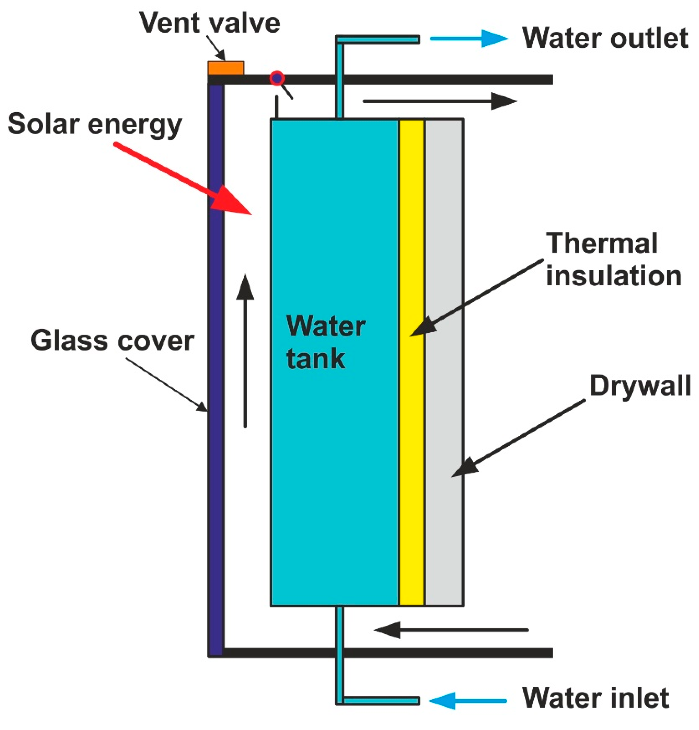
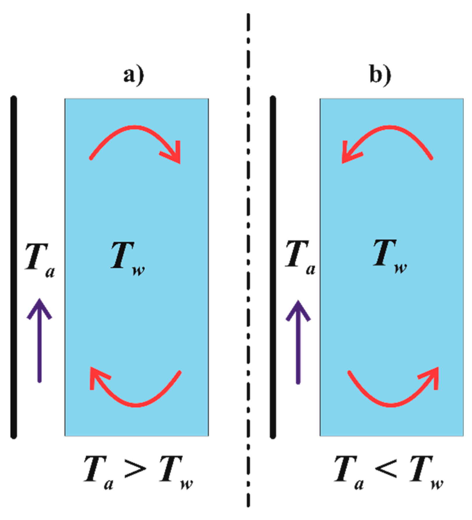
Figure 1 shows the schematic diagram of the proposed system. As the sun heats the absorber plate (outer side of the tank, painted matt back), the temperature of the absorber plate increases. Hence, the temperature of the water adjacent to the plate increases and its density decreases. The change in density enables water to circulate in a clockwise direction (charging process, Figure 2a). At night, the air temperature in the gap between the absorber plate and glass sheet is less than the water temperature. Therefore, the water in the tank circulates counterclockwise (discharging process, Figure 2b). Hence, the charging and discharging processes are controlled by a convection mechanism. In the conventional Trombe wall, the charging and discharging processes are controlled by heat diffusion mechanics. Since most materials used to construct the Trombe walls have low thermal diffusivity, the charging and discharging processes are slow, when compared to convection mechanisms. This is one of the advantages of the proposed system. To the authors’ knowledge, such a system has not been explored before.
For some reason, in the winter season, the room temperature may become higher than the air temperature in the gap. The one-way valve (thermal diode) that prevents reverse circulation is no more than a light sheet of a metal, such as aluminum, hinged at the top with a stopper at the bottom. The valve is operated by a pressure difference created due to the temperature difference. Hence, it must be very light. The valve prevents reverse circulation of the air.
The system works in the summer season, even in hot regions. The solar energy heats the water in the tank, which can be pumped for domestic uses, such as washing and/or taking showers. Hence, the effect of solar heating can be drastically reduced. Also, the vent valve can be opened so that the natural venting of air can take place by the chimney effect. We think that the proposed system can be efficiently utilized for heating and to some extent for the cooling of a building.
3. Comparison with the Conventional Trombe Walls
The proposed system has many advantages compared with conventional Trombe walls, which are summarized as follows:
- The specific heat and density of water are 4.186 kJ/(kg·K) and 1000 kg/m3, respectively. Hence, the heat capacity of water per unit volume is 4186 kJ/(m3·K). However, the specific heat and density of the concrete is about 0.880 kJ/(kg·K) and 2300 kg/m3, respectively. Hence, the heat capacity of the concrete per unit volume is about 2024 kJ/(m3·K). Therefore, for the same volume, the water tank can carry more than double the amount of thermal energy compared with concrete for the same temperature rise. The building brick has almost the same heating capacity as that of the concrete [37]. However, the water tank may need metal support, which adds extra weight.
- Heat losses in any thermal system are proportional to the temperature difference between the system and ambient temperature. Since the heat capacity of water is higher than the concrete, as mentioned above, the heat losses by convection and radiation from the water tank should be less than the concrete slab for the same amount of energy received from the sun.
- The charging and discharging processes from the proposed system occur by convection. While the charging and discharging processes from the concrete slab are done by the thermal diffusion process, it is a fact that convection heat transfer is a more efficient mechanism of heat transfer compared to the diffusion process.
- The main problem of conventional Trombe wall in the summer season is excessive heat, which overheats the building. However, in the proposed system, the water in the tank can be circulated. Hence, in the summer season, excess heat can be extracted out of the building.
- Furthermore, water is 2.3 times lighter than concrete (density ratio). Hence, the structure needed to support the water tank should be simpler. The metal cover of a water tank with a thickness of 6 mm can be used. Thus, the overall costs of the system may not be significant.
4. Thermal Modelling
The lumped capacity method is used to study the performance of the modified Trombe wall. Figure 3 shows the model cell. Staggered grid is used in dealing with advection term (the velocity nodes are shifted half control volume) compared with temperature nodes of water, absorbing plate and glass temperature nodes.
Glass cover:
Absorber:
Air:
Water:
where subscripts g, a, w, b and am stand for glass, air, water, absorber and ambient conditions, respectively. The heat transfer coefficient is represented by h. Glass transmissivity and absorptivity are denoted by τ and α, respectively. Density and specific heat are denoted by ρ and c, respectively. The last term in Equations (1) and (2) is due to the radiation heat transfer exchange between absorbing plate and glass cover, assuming the air is transparent. Stefan-Boltzmann constant, emissivity of glass, and emissivity of the absorber are denoted as σ, εg and εb, respectively.
In deriving the above equations, a few assumptions were made. It is assumed that air thermal capacity is negligible compared with water thermal capacity because the density of water multiplied by the heat capacity of the water is enormous (4186 kJ/(m3·K)) compared with that of air (1.0 kJ/m3·K). Also, it is assumed that the glass and absorber plate is very thin. Therefore, the effect of their thermal capacities is neglected. Furthermore, the axial heat conduction for the system is neglected compared with heat convection and advection.
Furthermore, the physical properties are assumed constants.
Initially, all elements of the system are set to the room temperature (20 °C), and the glass temperature is set to equal the ambient temperature (15 °C).
The explicit finite difference method is used to solve those equations iteratively because the air velocity is unknown prior to the solution.
The air flow velocity is calculated as:
where cd is the pressure drop coefficient that depends on the geometric shape of the opening. Its value is around 0.8 for wide openings. Ta,in, Ta,out, β and g are the air inlet temperature (room temperature), air outlet temperature, thermal expansion coefficient (1/(Troom, in K) and gravity acceleration, respectively.
Prior to the solution, the air outlet temperature is unknown. The procedure is to iterate the solution without updating the water temperature, which is a function of time. The air temperature increases due to solar energy heating. For each iteration, the velocity is updated until the outlet temperature does not vary considerably, less than 0.1 °C. Then, the water temperature is updated for each time step. The back of the tank is assumed to be perfectly insulated. Heat transfer coefficient between glass and ambient, ham, is set to 10 W/(m2·K), which is a typical value for moderate wind velocity conditions. The heat transfer coefficient between air and boundaries (glass sheet and absorber) is in the range of 20 W/(m2·K) to 50 W/(m2·K), depending on the air velocity. Heat transfer coefficient between the absorber and water is not well defined, because there is no reference temperature to calculate the Rayleigh number. The temperature varies with time. However, the heat transfer coefficient in the liquid side is higher than in the gaseous state. In this report, we used 100–200 W/(m2·K), as an educational guess, which is the typical range for natural convection in liquids. The sensitivity of the results for those coefficients is discussed in the results section.
Most of the published works use a width of 0.3–0.4 m for the storage tank and an air gap of 0.1 m. In our calculations, we used 0.3 m and 0.1 m for storage tank width and air gap, respectively. It is assumed that wall height is 3.0 m, which is a typical building wall height.
5. Results
The results are represented for the parameters summarized in Table 1, unless otherwise stated.
It is assumed that solar flux in term of the sine function:
where Imax is set to 1000 W/m2, and tmax = 36,000 s (10 h). The solar intensity reaches a maximum value after five hours.
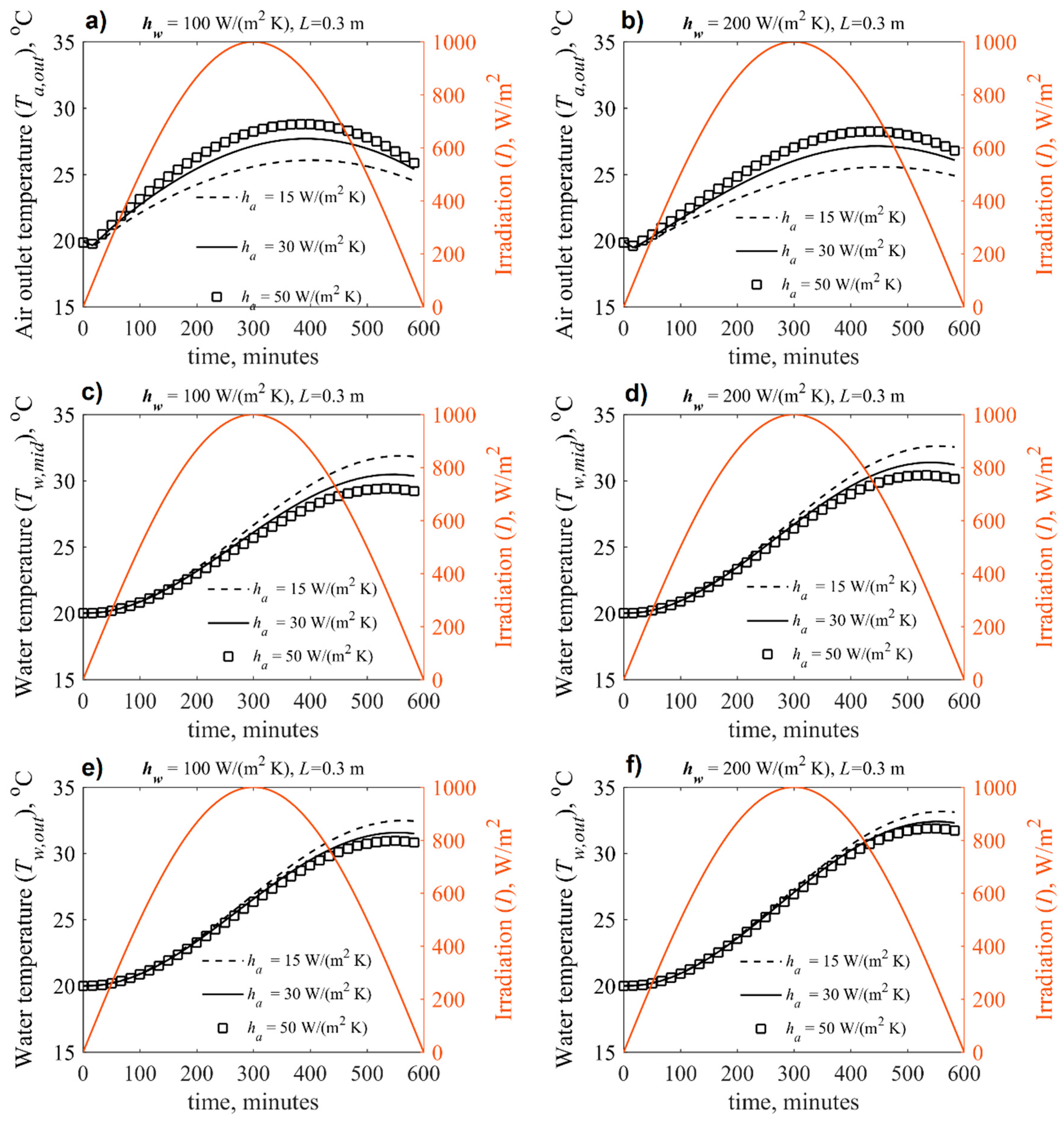
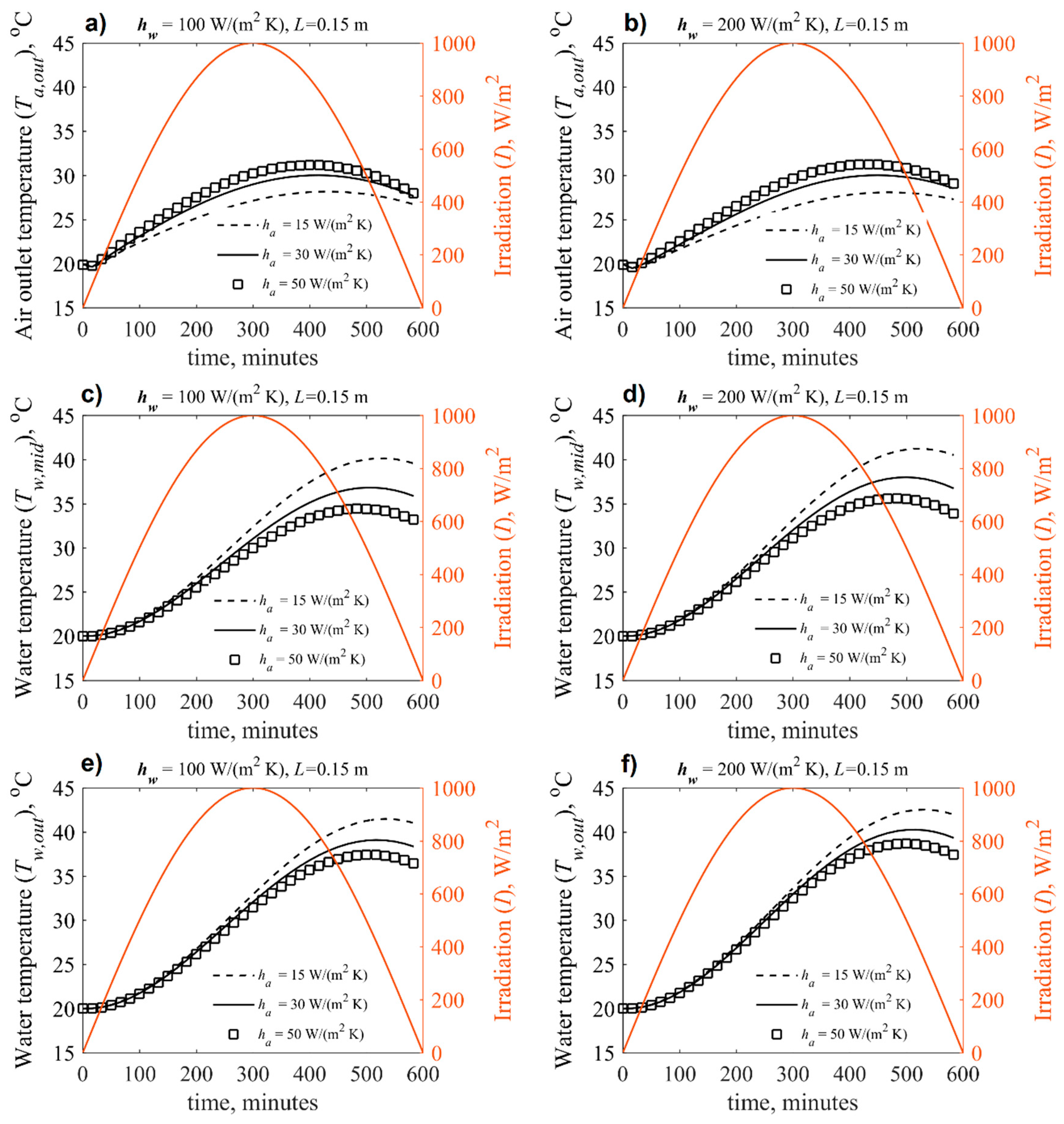
The transient response of the air outlet temperature, water temperature at the mid-height of the tank and water temperature at the top for the tank, for the tank width of 0.3 and 0.15 m, are shown in Figure 4 and Figure 5, respectively. The results are presented for different values of the heat transfer coefficient of air and two values of the heat transfer coefficient of water. From Figure 4 (width of tank = 0.3 m), the air temperature increases as the heat transfer coefficient of the air side increases, which is physically sound. The maximum increase in the outlet air temperature takes place after 350 min, while maximum solar heat intensity is at 300 min. The shift in the time of air outlet temperature is due to the water temperature increase with the solar flux. As long as the solar flux is not zero, energy added to the water is as shown in Figure 4c–f. The effect of increased heat transfer coefficient of the water side from 100 W/(m2·K) to 200 W/(m2·K) has a minimal impact on the air outlet temperature and water temperature. However, the tank size (width of tanks) has a significant impact on the system performance. This is expected because the water has high thermal capacity. For instance, the amount of energy stored in a tank with a width of 0.3 m will be doubled for the same increase in temperature compared with a tank of 0.15 m in width (half size). Of course, assuming that the length and height are the same for both tanks. Comparing Figure 4 and Figure 5, we can notice that the air outlet temperature increases by a few degrees for a tank of 0.15 m in width compared with a tank of 0.3 m width. However, the water in the tank showed a significant increase in temperature as the tank width decreased. Also, the effect of the air-side heat transfer coefficient is noticeable on the water temperature, especially after a decrease in solar intensity.
We can conclude from these results that optimizing the storage tank size is an essential factor and depends on the heating load and thermal characteristics of a given building. Also, the results reveal that the heat transfer coefficient of the air side should be correctly estimated for small tanks. In fact, the effective heat transfer coefficient can be controlled, for example, by adding extended surfaces (fins) or turbulent generators.
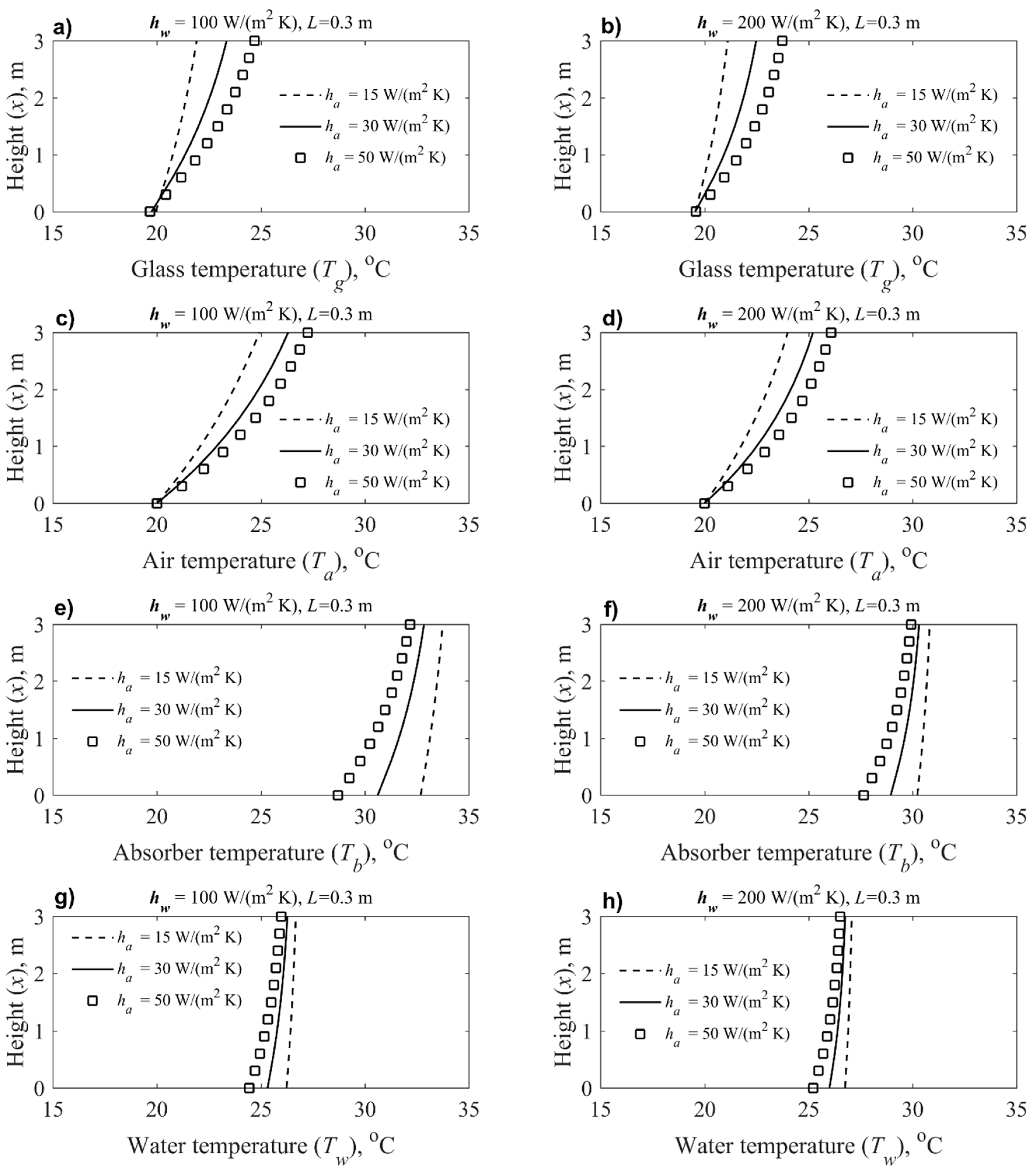
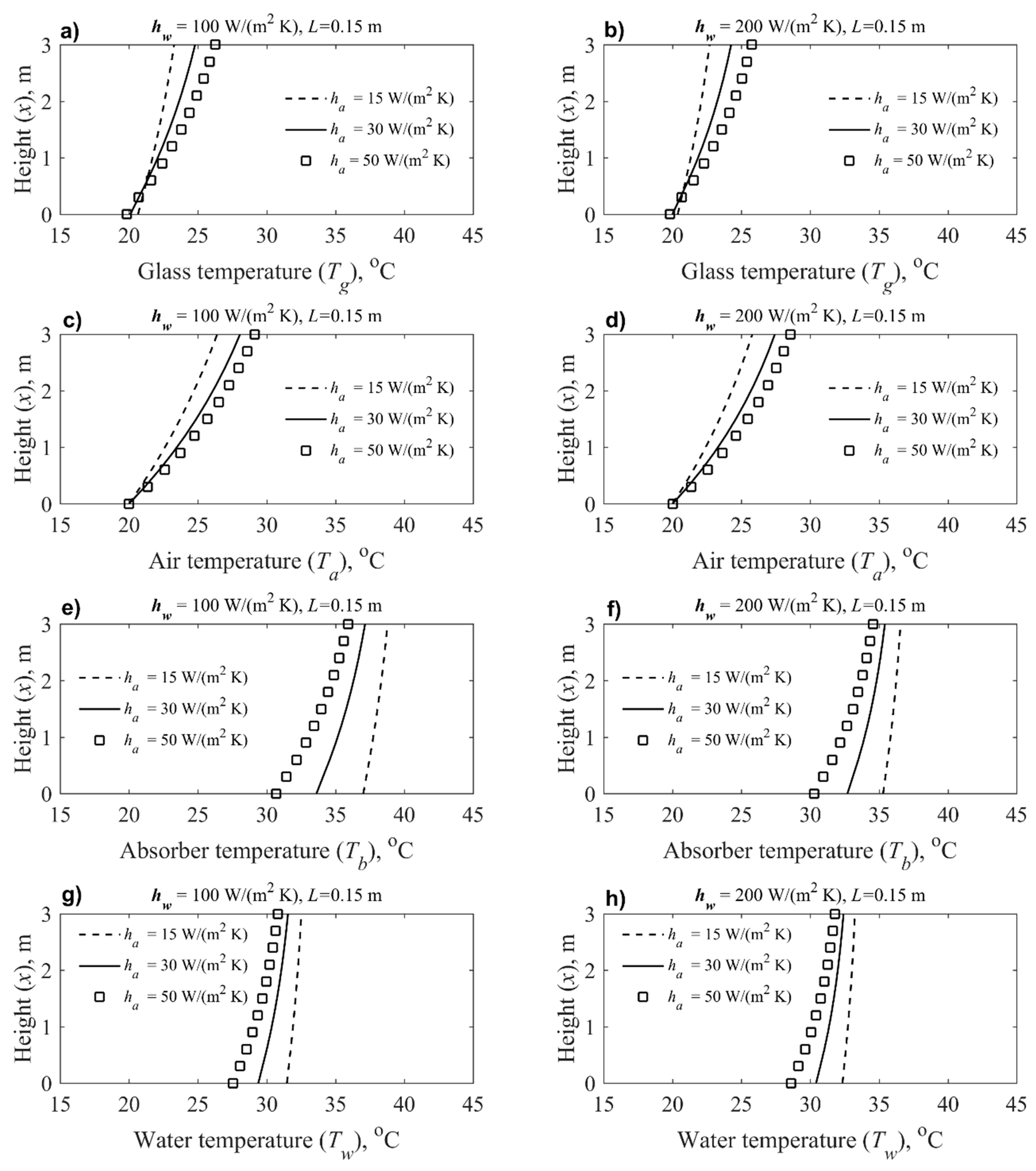
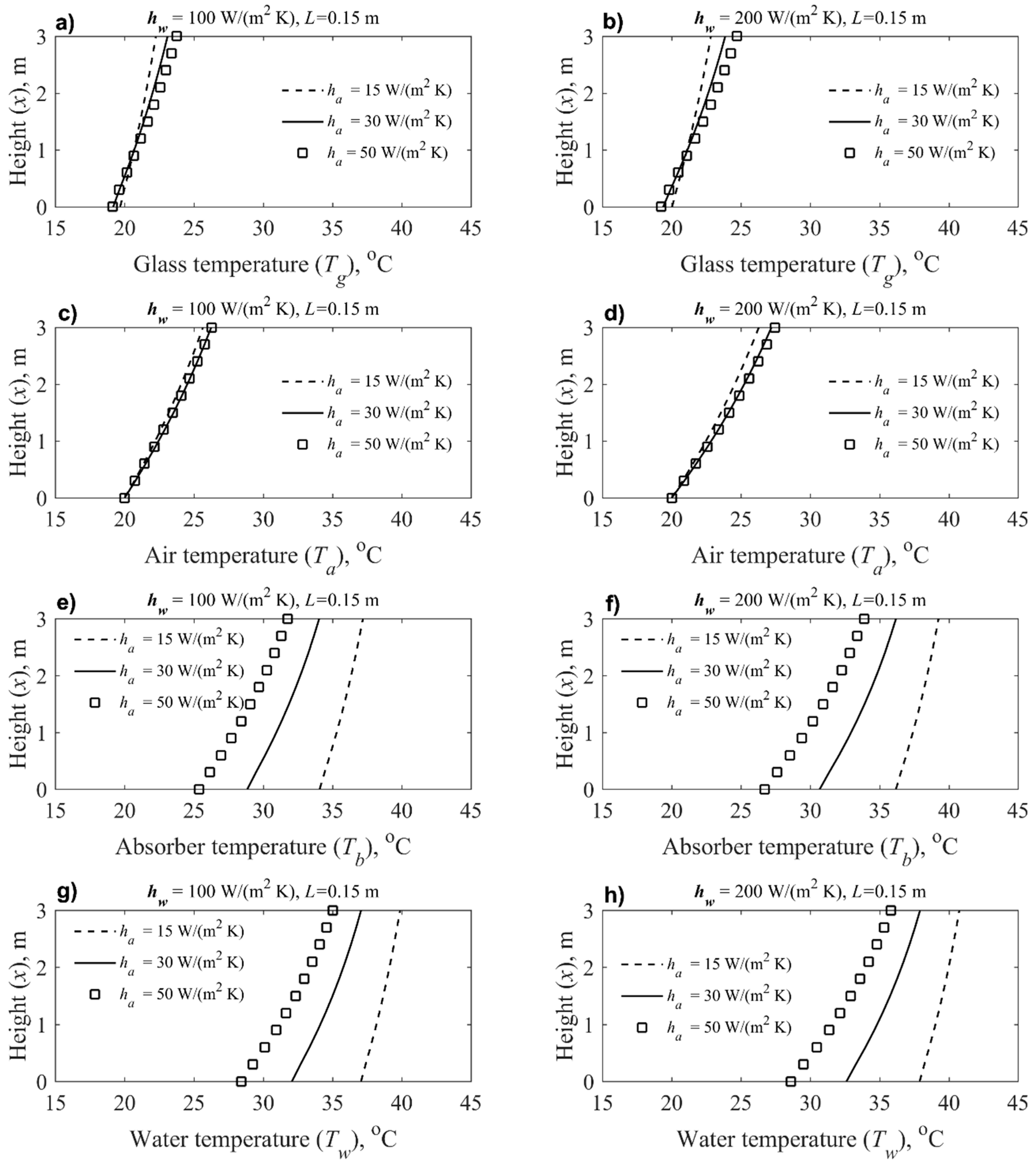
The performance of the system is further analyzed. Figure 6 and Figure 7 shows the temperature distribution of glass, air, absorber and water along the system for tank width of 0.3 m and 0.15 m, respectively. The glass temperature increases to almost room temperature at the bottom and its temperature increases along the x-axis (height of the system). It is sensitive to the air side of the heat transfer coefficient. In this instance, the glass temperature can reach 25 °C at the x = 3.0 m, for both sizes of the tank. Hence, heat transfer is lost as the ambient temperature increases. This suggested that using double glazing will be beneficial, especially in a windy environment.
The predictions of temperature distribution at the time of 300 min, where the solar flux is maximum, will be discussed in the following paragraph.
For tank width, equal to 0.3 m (let us call it tank I), the air temperature along the x-axis is not that sensitive to the heat transfer coefficient of the water side. However, it shows that as the heat transfer coefficient increases, the temperature increases. The difference between predictions of ha = 30 W/(m2·K) and 50 W/(m2·K) is about a few degrees at the outlet. The mentioned difference decreases as the tanks size decreases (compare Figure 6 and Figure 7).
The air outlet temperature can reach about 28 °C for tank I and about 30 °C for tank II (tank of 0.15 m in width). The absorber plate temperature can reach about 35 °C and 30 °C for hw of 100 W/(m2·K) and 200 W/(m2·K), respectively for tank I. However, for tank II, the plate temperature can reach 40 °C and about 37 °C, for hw of 100 and 200 W/(m2·K), respectively. The water in the tank showed slight stratification (variation of the temperature) along the x-axis for all the investigated parameters. As mentioned before, the temperature in the tank is significantly higher for tank II when compared with tank I. The amount of energy in the system for the period of 10 h is the same. Therefore, we should expect that the amount of energy stored in tank II and tank I will be the same, unless the loss of heat is the difference. Examining Figure 6 and Figure 7 shows that the average water temperature in tank I increased from an initial temperature of 20 °C to about 27 °C. However, the water temperature in tank II increases from an initial temperature of 20 °C to about 34 °C.
The energy stored in the system is equal to the mass of the water multiplied by the heat capacity of the water and to the temperature rise (Q = m·c·ΔT). The ratio of energy stored in the tank I (0.3 m in width) to energy stored in tank II (0.15 m in width) is (0.3·(27 − 20)/(0.15·(34 − 20)), which is about 1.0. This means that the heat loss is almost the same for both tanks.
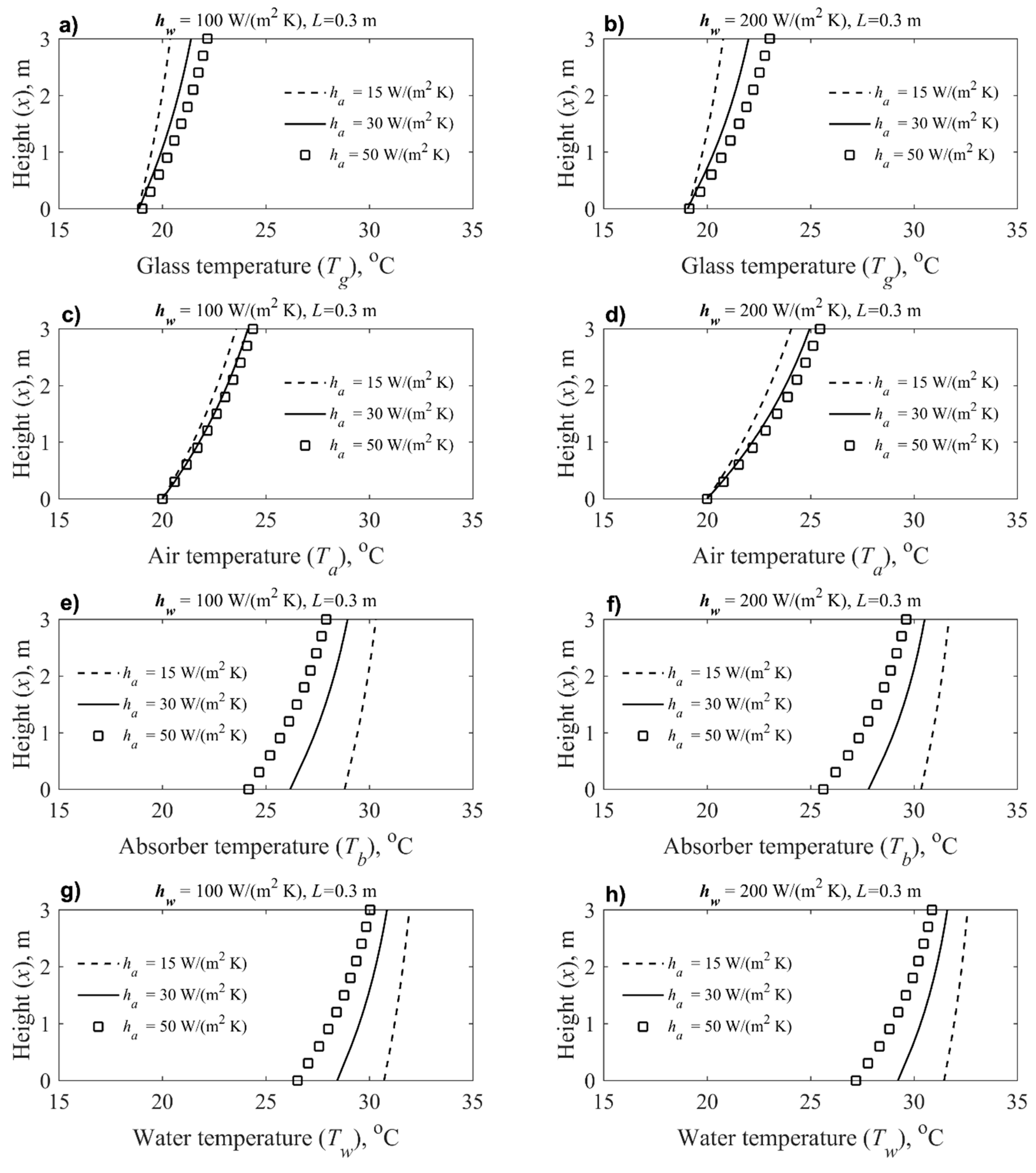
Figure 8 and Figure 9 show the temperature variations along the x-axis similar to Figure 6 and Figure 7 but after 10 h from system operation. At the time of 10 h (600 min), the solar flux reaches a minimum value (zero). It can be seen that the effect of the air side heat transfer coefficient becomes significant on the water and absorbing temperatures. Also, the temperature in the tank exceeds the absorber temperature by a few degrees.
6. Energy and Efficiency
The amount of solar energy (J/m) received by the system is:
where tt is the total time (10 h).
The energy absorbed by the water (J/m) is calculated as:
where Ti and Ti+1 are the initial and final temperature of the water.
The energy carried by air is calculated as:
The thermal efficiency of the system is defined as:
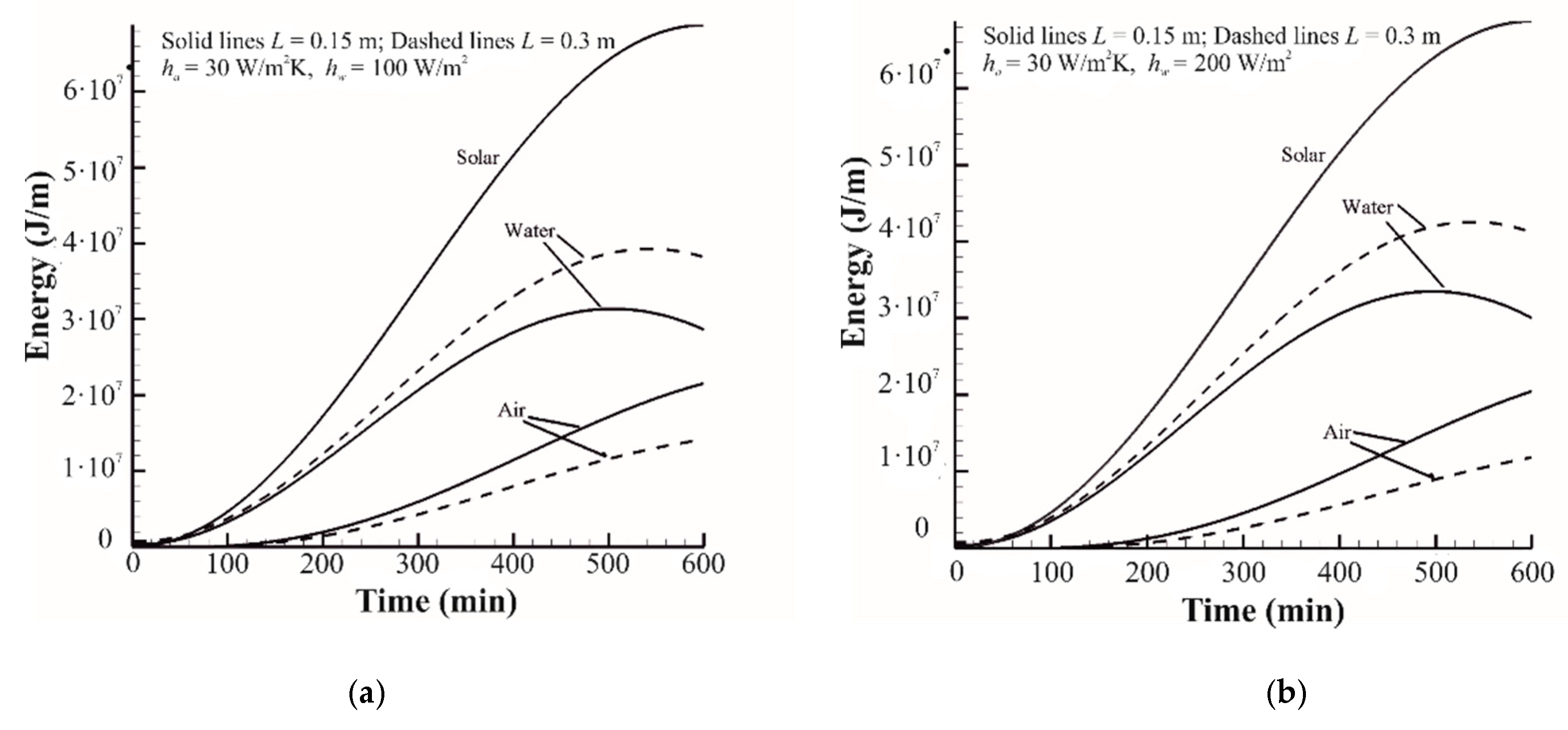
The total solar energy that hits the system during the 10 h time period requires integration of Equation (7), which is 68,755 × 103 kJ/m. Figure 10a,b, show the energy accumulated by the water and energy conveyed by air to the room, and total solar energy in the system (J/m) for hw = 100 W/(m2·K) and hw = 200 W/(m2·K), respectively. The tendency is that energy accumulated in the water tank increases as the solar energy increases and reaches peak value at 300 min. However, at the time of about 500 min, the total energy in the tank decreases. The solar energy is not enough to keep the absorber temperature more than the water temperature (see Figure 9). After this period, the water starts feeding air with energy, which ensures that the air’s outlet temperature is less affected by a drop in the solar intensity constant, Figure 8.
Examining Figure 10 shows that the energy accumulated in the water for a tank of width 0.3 m is higher than that for a tank of width 0.15 m, for the same amount of solar energy. For example, for hw = 100 W/(m2·K), the amount of energy accumulated in the tank of 0.3 m and 0.15 m in width are 38,186 × 103 kJ/m and 28,616 × 103 kJ/m, respectively. The results physically make sense. For the same amount of energy, the increase in temperature will be less for a large volume of water. Since the heat losses are a function of the temperature difference between the system and ambient, the heat losses are lower for the larger tank with L = 0.3 m. This fact is also reflected in Figure 11.
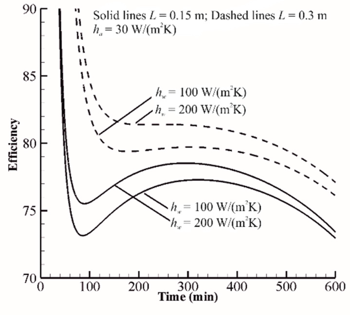
As is clear from Figure 11, efficiency is very high at the starting point of the system. This is because the temperature gradient between the system and ambient is very low. Accordingly, the heat losses are minimum. However, as the system temperature increases, the heat losses decrease. Later, the amount of energy accumulated in the system increases, enhancing efficiency.
From Figure 5, for a smaller tank with L = 0.15 m, the water temperature exceeds 30 C after 300 min, what is sufficient for washing or showering purposes. After 400 min, the water temperature reaches 38 °C for air heat transfer coefficient of 15 W/(m2·K), which is an ideal temperature for washing. From Figure 4, one can observe that at L = 0.3 m, the system does not work very well, and the temperature of water is lower than that at L = 0.15 m. The reason for this is that a larger volume of water needs to be heated. However, the heat losses for a ‘larger’ tank with L = 0.3 m are lower than for a ‘smaller’ tank with L = 0.15 m, and the efficiency of the larger tank is higher (Figure 11). Therefore, the large room exists on optimization of such a modified Tromble wall system.
7. Conclusions
A modified Trombe wall is introduced for energy saving in buildings. The system can be utilized for heating in the winter season. The system also reduces the effect of solar heating in the summer season. However, instead of venting the solar energy-heated air, the energy can be utilized for domestic water-heating purposes. Furthermore, the system can assist in ventilation by the chimney effect.
The first order analysis was performed to illustrate the sensitivity of the system for a few controlling parameters. The system showed that the air side heat transfer coefficient is an important parameter that needs to be estimated correctly. The effective heat transfer coefficient can be augmented by adding extended surfaces; however, it will be to the cost and weight of the system. Since the system receives the same amount of energy for a given period, reducing the tank size increases the temperature. However, the amount of energy stored in the tank is not significantly affected by the size of the tank, at least for the investigated range. The thermal storage efficiency is more than 70%, which demonstrates that the system is efficient in saving thermal energy. Further work on optimizing tank size, as a function of energy demand, is ongoing. An experimental setup is also in process.
Author Contributions
A.M. developed the concept and model of a modified Tromble wall, as well as prepared a draft of paper and a MATLAB code for Tromble wall simulation; J.T. performed manuscript editing and supported the development of the mathematical model of Tromble wall; P.O. performed a literature survey with A.M., checked the MATLAB model of the Tromble wall developed by A.M., and wrote a MATLAB code for visualization of temperature results (Figure 4, Figure 5, Figure 6, Figure 7, Figure 8, Figure 9 and Figure 10).
Funding
This reaserch was funded by Cracow Unviersity of Technology own Research Grant No. 2336/2018.
Conflicts of Interest
The authors declare no conflict of interest.
References
- Llovera, J.; Potau, X.; Medrano, M.; Cabeza, L.F. Desgin and performance of energy-efficient solar residential house in Andorra. Appl. Energy 2011, 88, 1343–1353. [Google Scholar] [CrossRef]
- Trombe, F.; Robert, J.F.; Cabanat, M.; Sesolis, B. Some performance characteristics of the CNRS solar house collectors. In Proceedings of the Passive Solar Heating and Cooling Conference and Workshop, Los Alamos Scientific Laboratory Report LA-6637-C, Albuquerque, NM, USA, 18–19 May 1976; pp. 201–202. [Google Scholar]
- Akbarzadeh, A.; Charters, W.W.S.; Lesslie, D.A. Thermocirucultation Characteristics of a Trombe Wall Passive Test Cell. Sol. Energy 1982, 28, 461–468. [Google Scholar] [CrossRef]
- Ben Yedder, R.; Bilgen, E. Natural convection and conduction in Trombe wall systems. Int. J. Heat Mass Transf. 1991, 34, 1237–1248. [Google Scholar] [CrossRef]
- Tunc, M.; Uysal, M. Passive solar heating of buildings using a fluidized bed plus Trombe wall system. Appl. Energy 1991, 38, 199–213. [Google Scholar] [CrossRef]
- Chen, W.; Liu, W. Numerical analysis of heat transfer in a composite wall solar-collector system with a porous absorber. Appl. Energy 2004, 78, 137–149. [Google Scholar] [CrossRef]
- Jaber, S.; Ajib, S. Optimum design of Trombe wall system in Mediterranean region. Sol. Energy 2011, 85, 1891–1898. [Google Scholar] [CrossRef]
- Duffie, J.; Beckman, W. Solar Engineering of Thermal Processes; John Wiley and Sons, Inc.: Hoboken, NJ, USA, 2006. [Google Scholar]
- Sun, W.; Ji, J.; Luo, C.; He, W. Performance of PV-Trombe wall in winter correlated with south façade design. Appl. Energy 2011, 88, 224–231. [Google Scholar] [CrossRef]
- Saadatian, O.; Sopian, K.; Lim, C.H.; Asim, N.; Sulaiman, M.Y. Trombe walls: A review of opportunities and challenges in research and development. Renew. Sustain. Energy Rev. 2012, 16, 6340–6351. [Google Scholar] [CrossRef]
- Bajc, T.; Todorovic, M.N.; Svorcan, J. CFD analyses for passive house with Trombe wall and impact to energy demand. Energy Build. 2015, 98, 39–44. [Google Scholar] [CrossRef]
- He, W.; Hu, Z.; Luo, B.; Hong, X.; Sun, W.; Ji, J. The thermal behavior of Trombe wall system with Venetian blind: An experimental and numerical study. Energy Build. 2015, 104, 395–404. [Google Scholar] [CrossRef]
- He, W.; Hong, X.; Wu, X.; Pei, G.; Hu, Z.; Tang, W.; Shen, Z.; Ji, J. Thermal and hydraulic analysis on a novel Trombe wall with Venetian blind structure. Energy Build. 2016, 123, 50–58. [Google Scholar] [CrossRef]
- Hernandez-Lopez, I.; Xaman, J.; Chavez, Y.; Henandez-Perez, I.; Alvarado-Juarez, R. Thermal energy storage and losses in a room-Trombe wall system located in Mexico. Energy 2016, 109, 512–524. [Google Scholar] [CrossRef]
- Taffesse, F.; Verma, A.; Singh, S.; Tiwari, G.N. Periodic modeling of semi-transparent photovoltaic thermal-Trombe wall (SPVT-TW). Sol. Energy 2016, 135, 265–273. [Google Scholar] [CrossRef]
- Duan, S.; Jing, C.; Zhao, Z. Energy and exergy analysis of different Trombe walls. Energy Build. 2016, 126, 517–523. [Google Scholar] [CrossRef]
- Jovana, J.; Sun, X.; Stevovic, S.; Chen, J. Energy-efficiency gain by combination of PV modules and Trombe wall in the low-energy building design. Energy Build. 2017, 152, 568–576. [Google Scholar]
- Hu, Z.; He, W.; Ji, J.; Hu, D.; Lv, S.; Chen, H.; Shen, Z. Comparative study on the annual performance of three types of building integrated photovoltaic (BIPV) Trombe wall system. Appl. Energy 2017, 194, 81–93. [Google Scholar] [CrossRef]
- Hu, Z.; He, W.; Hu, D.; Lv, S.; Wang, L.; Ji, J.; Chen, H.; Ma, J. Design, construction and performance testing of a PV blind-integrated Trombe wall module. Appl. Energy 2017, 203, 643–656. [Google Scholar] [CrossRef]
- Yu, B.; He, W.; Li, N.; Wang, L.; Cai, J.; Chen, H.; Ji, J.; Xu, G. Experimental and numerical performance analysis of a TC-Trombe wall. Appl. Energy 2017, 206, 70–82. [Google Scholar] [CrossRef]
- Rabani, M.; Kalantar, V.; Rabani, M. Heat transfer analysis of a Trombe wall with a projecting channel design. Energy 2017, 134, 943–950. [Google Scholar] [CrossRef]
- Luo, Y.; Zhang, L.; Wu, J.; Liu, Z.; Wu, Z.; He, W. Dynamical simulation of building integrated photovoltaic thermoelectric wall system: Balancing calculation speed and accuracy. Appl. Energy 2017, 204, 887–897. [Google Scholar] [CrossRef]
- Jayathissa, P.; Luzzatto, M.; Schmidli, J.; Hofer, J.; Nagy, Z.; Schlueter, A. Optimising building net energy demand with dynamic BIPV shading. Appl. Energy 2017, 202, 726–735. [Google Scholar] [CrossRef]
- Hong, S.; Choi, A.-S.; Sung, M. Development and verification of a slat control method for a bi-directional PV blind. Appl. Energy 2017, 206, 1321–1333. [Google Scholar] [CrossRef]
- Corasaniti, S.; Manni, L.; Russo, F.; Gori, F. Numerical simulation of modified Trombe-Michel Walls with exergy and energy analysis. Int. Commun. Heat Mass Transf. 2017, 88, 269–276. [Google Scholar] [CrossRef]
- Leang, E.; Tittelein, P.; Zalewski, L.; Lassue, S. Numerical study of a composite Trombe solar wall integrating microencapsulated PCM. Energy Procedia 2017, 122, 1009–1014. [Google Scholar] [CrossRef]
- Hu, Z.; He Ji, J.; Zhang, S. A review on the application of Trombe wall system in buildings. Renew. Sustain. Energy Rev. 2017, 70, 976–987. [Google Scholar] [CrossRef]
- Ma, Q.; Fukuda, H.; Lee, M.; Kobatake, T.; Kuma, Y.; Ozaki, A. Study on the utilization of heat in the mechanically ventilated Trombe wall in a house with a central air conditioning and air circulation system. Appl. Energy 2018, 222, 861–871. [Google Scholar] [CrossRef]
- Long, J.; Yongga, A.; Sun, H. Thermal insulation performance of a Trombe wall combined with collector and reflection layer in hot summer and cold winter zone. Energy Build. 2018, 171, 144–154. [Google Scholar] [CrossRef]
- Souayfane, F.; Biwole, P.H.; Fardoun, F. Thermal behavior of a translucent superinsulated latent heat energy storage wall in summertime. Appl. Energy 2018, 217, 390–408. [Google Scholar] [CrossRef]
- Yu, B.; Jiang, Q.; He, W.; Hu, Z.; Chen, H.; Ji, J.; Xu, G. The performance analysis of a novel TC-Trombe wall system in heating seasons. Energy Convers. Manag. 2018, 164, 242–261. [Google Scholar] [CrossRef]
- Bernardo, L.R.; Davidsson, H.; Karlsson, B. Retrofitting Domestic Hot Water Heaters for Solar Water Heating Systems in Single-Family Houses in a Cold Climate: A Theoretical Analysis. Energies 2012, 5, 4110–4131. [Google Scholar] [CrossRef] [Green Version]
- Fu, X.; Qian, X.; Wang, L. Energy Efficiency for Airtightness and Exterior Wall Insulation of Passive Houses in Hot Summer and Cold Winter Zone of China. Sustainability 2017, 9, 1097. [Google Scholar]
- Haggag, M.; Hassan, A.; Qadir, G. Energy and Economic Performance of Plant-Shaded Building Façade in Hot Arid Climate. Sustainability 2017, 9, 2026. [Google Scholar] [CrossRef]
- Huang, L.; Zheng, R. Energy and Economic Performance of Solar Cooling Systems in the Hot-Summer and Cold-Winter Zone. Buildings 2018, 8, 37. [Google Scholar] [CrossRef]
- Lanahan, M.; Tabares-Velasco, P.C. Seasonal Thermal-Energy Storage: A Critical Review on BTES Systems, Modeling, and System Design for Higher System Efficiency. Energies 2017, 10, 743. [Google Scholar] [CrossRef]
- Incropera, F.P.; DeWitt, D.P. Fundamentals of Heat and Mass Transfer, 5th ed.; John Wiley & Sons: New York, NY, USA, 2002. [Google Scholar]
Figure 1.
Schematic diagram of the modified Trombe wall.

Figure 2.
Charging (a) and discharging; (b) processes of the system.

Figure 3.
Computational scheme of the problem.
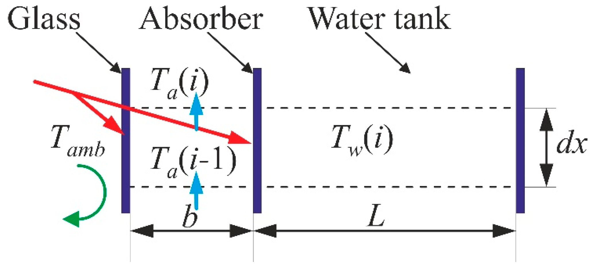
Figure 4.
The variations of air outlet temperature (a,b), at mid-height (c,d) and top (e,f) of the tank’s water temperature for tank width of 0.3 m. Subfigures (a,c and e) are obtained for hw = 100 W/(m2·K) while subfigures (b,d and f) are obtained for hw = 200 W/(m2·K).
Figure 4.
The variations of air outlet temperature (a,b), at mid-height (c,d) and top (e,f) of the tank’s water temperature for tank width of 0.3 m. Subfigures (a,c and e) are obtained for hw = 100 W/(m2·K) while subfigures (b,d and f) are obtained for hw = 200 W/(m2·K).

Figure 5.
The variations of air outlet temperature (a,b), at mid-height (c,d) and top (e,f) of the tank’s water temperature for tank width of 0.15 m. Subfigures (a,c and e) are obtained for hw = 100 W/(m2·K) while subfigures (b,d and f) are obtained for hw = 200 W/(m2·K).
Figure 5.
The variations of air outlet temperature (a,b), at mid-height (c,d) and top (e,f) of the tank’s water temperature for tank width of 0.15 m. Subfigures (a,c and e) are obtained for hw = 100 W/(m2·K) while subfigures (b,d and f) are obtained for hw = 200 W/(m2·K).

Figure 6.
The temperature variations of the different elements of the system: (a,b) glass temperature; (c,d) air temperature; (e,f) absorber temperature; (g,h) water temperature as a function of the system height for the tank of 0.3 m in width, after 5 h. Subfigures (a,c,e and g) are obtained for hw = 100 W/(m2·K) while (b,d,f and h) for hw = 200 W/(m2·K).

Figure 7.
The temperature variations of the different elements of the system: (a,b) glass temperature; (c,d) air temperature; (e,f) absorber temperature; (g,h) water temperature as a function of the system height for the tank of 0.15 m in width, after 5 h. Subfigures (a,c,e and g) are obtained for hw = 100 W/(m2·K) while (b,d,f and h) for hw = 200 W/(m2·K).

Figure 8.
The temperature variations of the different elements of the system: (a,b) glass temperature; (c,d) air temperature; (e,f) absorber temperature; (g,h) water temperature as a function of the system height for the tank of 0.3 m in width, after 10 h. Subfigures (a,c,e and g) are obtained for hw = 100 W/(m2·K) while (b,d,f, and h) for hw = 100 W/(m2·K).

Figure 9.
The temperature variations of the different elements of the system: (a,b) glass temperature; (c,d) air temperature; (e,f) absorber temperature; (g,h) water temperature as a function of the system height for the tank of 0.15 m in width, after 10 h. Subfigures (a,c,e and g) are obtained for hw = 100 W/(m2·K) while (b,d,f and h) for hw = 200 W/(m2·K).

Figure 10.
Energy versus time in the system, (a) for hw = 100 (W/m2·K) and (b) for hw = 200 W/(m2·K).
Figure 10.
Energy versus time in the system, (a) for hw = 100 (W/m2·K) and (b) for hw = 200 W/(m2·K).

Figure 11.
Efficiency versus time.


Table 1.
Parameters of the modified Trombe wall analysis.
| Parameters | Water Properties | Air Properties | Geometry |
|---|---|---|---|
| ham = 10 W/(m2·K) ha = 30 and 50 W/(m2·K) hw = 100 W/(m2·K), and 200 W/(m2·K) αp = 0.94 αg = 0.02 τg = 0.97 Tamb = 15 °C Troom = 20 °C | ρw = 1000 kg/m3 cw = 4186 J/(kg·K) | ρa = 1.0 kg/m3 ca = 1000 J/(kg·K) | b = 0.1 m L = 0.15 and 0.3 m H = 3.0 m |
© 2019 by the authors. Licensee MDPI, Basel, Switzerland. This article is an open access article distributed under the terms and conditions of the Creative Commons Attribution (CC BY) license (http://creativecommons.org/licenses/by/4.0/).
Share and Cite
MDPI and ACS Style
Mohamad, A.; Taler, J.; Ocłoń, P. Trombe Wall Utilization for Cold and Hot Climate Conditions. Energies 2019, 12, 285. https://doi.org/10.3390/en12020285
AMA Style
Mohamad A, Taler J, Ocłoń P. Trombe Wall Utilization for Cold and Hot Climate Conditions. Energies. 2019; 12(2):285. https://doi.org/10.3390/en12020285
Chicago/Turabian StyleMohamad, Abdulmajeed, Jan Taler, and Paweł Ocłoń. 2019. "Trombe Wall Utilization for Cold and Hot Climate Conditions" Energies 12, no. 2: 285. https://doi.org/10.3390/en12020285
Note that from the first issue of 2016, this journal uses article numbers instead of page numbers. See further details here.