The Effect of Trailing Edge Clearance in Suppressing Hub-Corner Stall

College of Power and Energy Engineering, Harbin Engineering University, Harbin 150001, China
*
Authors to whom correspondence should be addressed.
Energies 2019, 12(2), 256; https://doi.org/10.3390/en12020256
Submission received: 9 December 2018
/
Revised: 7 January 2019
/
Accepted: 10 January 2019
/
Published: 15 January 2019
Abstract
:Hub corner is a high-loss area located within in the blade passages of turbomachinery. It is well known that flow separation and vortex development in this area directly affects, not only energy loss and efficiency, but also the stability of axial compressors. In this paper, a high diffusion factor cascade is used in order to analyze the vortex structure which causes the hub-corner stall in cascade. The trailing edge clearance method is proposed for controlling the hub-boundary layer and this is compared with full uniform clearance. Our research highlights that the trailing edge clearance suppress the radial development of the suction separation vortex (SSV) in the hub corner and restrains the concentrated separation vortex (CSV). The influence of trailing edge clearance parameters and its effect on control of hub-corner stall is discussed in detail. It is revealed that clearance height avoids flow separation and suppresses radial vortex development, while the clearance length resists the overturning that is caused by transverse pressure gradient and controls the development of CSV. As the radial vortex plays a dominant role in hub-corner stall, clearance height has a better effect in controlling hub-corner stall in comparison to length at the constant flow area.
1. Introduction
The axial compressor is an important component of a modern gas turbine. It has a significant effect on the overall performance of a gas turbine and its stable operation. Today, the high pressure ratio highly-loaded axial compressor has become commonplace in compressor design and development [1]. The large angle of attack increases the compressor trailing edge diffuser size at lower mass flow rates, which causes hub-corner stall and results in the reduction of stall margin. At present, the design of turbomachinery is optimized by reducing flow loss. In order to enhance the single stage pressure ratio of the compressor, the turning angle of the rotor needs to be increased. However, the increase in the turning angle causes flow separation in rotor suction surface. The highly loaded-rotor has higher leakage flow at the tip clearance of rotor blades. The interaction between this stronger leakage flow and trailing edge radial flow causes the stall at lower operating conditions in a highly-loaded compressor. The application of flow control methods based on rotor blades is difficult to implement on real compressors. However, flow control methods based on stator can be easily comprehended and applied in engineering applications. Therefore, there is a requirement to study these stator flow control technologies.
Good off-design performance in stationary cascades can improve the stall margin of the compressor stage. In stator, hub-corner stall is an important factor that affects the stall margin of the compressor. There is a strong inverse pressure gradient and transverse secondary flow in the stator. Three-dimensional (3-D) separation is one of the most important factors limiting the loading capacity of compressors. This is an inherent feature of flow, and it found in the end wall region, mainly in the hub corner of the blade passage. It increases flow blockage and overall loss, thus limiting compressor efficiency and stability [2,3,4]. The 3-D corner separation causes adverse effects, which lead to stall and a surge of the highly-loaded compressor, such as flow passage blockage, limiting static pressure rise, increase in total pressure loss, and reduction in compressor efficiency [5]. At present, the numbers of remedial design methods are being researched in order to reduce hub-corner separation. Corner separation control is broadly divided into two types: Active control and passive control. The active control method controls the flow field in transient working conditions. It requires additional ancillary devices. The passive control technology does not require additional devices. However, it cannot make the corresponding adjustment to changes in the flow field. Williamson [6] investigated corner separation and achieved higher stall margin in a highly-loaded compressor cascade using plasma actuators. Williamson revealed that the installation of a combination of plasma actuators upstream of the corner separation point gives the most beneficial effect. Li [7] compared the ability of hub-corner improvement at different Reynolds numbers using trailing edge fluid flow. Antonia [8] investigated the relationship between boundary layer suction ratio and cascade performance using a boundary layer suction method. Other methods have also been reported, such as variable inlet guide vane and casing treatment.
Schobeiri researched and applied variable inlet guide vane (VG) technology in multi-stage compressor, which caused a significant increase in surge margin i.e., fully stable operation regime [9]. NASA (National Aeronautics and Space Administration) has designed a new four-stage compressor with a pressure ratio of 6. In this new design system, variable inlet guide vane is used to broaden the compressor margin [10]. Linder and Jones have conducted an experimental study on a single stage compressor in order to analyze the effect of VG on the compressor in off-design condition by comparing preswirl and non-preswirl [11]. Serovy and Kavanagh have studied the influence of variable guide vane geometry on the design of an axial compressor [12].
Casing treatment is widely used in aviation compressors. Greitzer studied the influence of hub slot (casing treatment) structure on the flow of cantilever stator tip. He found that at the trailing edge of the blade passage, the slot absorbs the low-energy blockage zone caused by the clearance leakage flow at the tip of the blade passage. Moreover, the low-energy leakage flow is energized by the high-energy jet to inhibit its development at the leading edge of the blade passage [13]. Cumpsty studied the effect of an axial skewed slot on low speed compressor rotors. His research showed that the pressure difference in the rotor channel sucks the tip clearance of the compressor rotor trailing edge back into the treatment slot. Following this, it re-enters the main stream of the passage at the leading edge of the rotor, which restrains the flow/gap leakage flow from moving upstream to the compressor rotor, thus effectively improving the stability margin of the compressor rotor [14]. Takata found that the inclined slot has a good stabilizing effect, but its application is inconvenient and has relatively more efficiency loss [15]. Efficiency loss is the main factor limiting casing treatment.
Driven by the pressure difference, leakage flow travels across the clearance from the pressure surface to the suction surface. When the leakage flow enters the passage, it interacts with the mainstream and leads to a hub leakage vortex. The leakage vortex caused by clearance restrains the radial development of hub separation. The bowed and swept blade, a passive control method, has been used in the design of a marine compressor [16,17,18,19]. In marine gas turbines, it is important to meet the requirements of quick acceleration and deceleration. The variable inlet guide vane method enhances the stable operation range of the compressor. However, at lower mass flow rates the stator blade at the rear stage faces a higher attack angle. This leads to hub-corner stall at the root of the stator blade. Hub-corner stall is the main limitation of variable inlet guide vane control method. Hub-clearance method nullifies the limitation of variable inlet guide vane and effects the boundary layer of the blade surfaces and hub wall. A number of research studies are currently analyzing the hub-clearance method. It increases the stall margin and is effective at lower mass flow rates. However, this method will cause higher leakage loss due to the nature of the design. At present, scholars have focused more attention on the clearance of rotors, meaning that less research has been conducted on stators [20,21,22]. Lee studied a 10-stage axial flow compressor, and his research shows that the leakage flow generated by compressor stator clearance can depress the three-dimensional flow separation in corners and improve compressor efficiency [23]. Gbadebo [24] found that the inhibition of tip clearance flow on corner separation was related to the interaction between the leading horseshoe vortex and the hub. Zuo [25] studied the effect of stator hub clearance on the performance of high-load compressor and found that suitable clearance structure can restrain secondary flow near stator root, delay compressor stall, and enlarge compressor stability. Ribi [26] found that hub clearance increased the stability margin of the compressor, but decreased the efficiency and pressure ratio of the compressor. In order to reduce the leakage loss, some scholars have proposed partial clearances to control the flow field in the corner [27]. In his study of plane cascades, Zhao [28] found that the more backward the position of the partial clearances, the better the flow field control effect in the corner. At the same time, the length of the trailing edge should not be too small, as an overly small trailing edge will increase cascade loss.
When considering previous studies, it can be found that the method of clearance to eliminate the hub-corner separation/stall of compressor is feasible and effective. Usually, when the flow field of the compressor is at design point, the leakage flow produced by the clearance will reduce the performance of the compressor. In this paper, the high diffusion factor cascade is taken as the research object, as the corner separation of cascade is a very important research issue. In order to comprehensively consider the effect of clearance on cascade performance, calculation with variable incident is also carried out.
2. Cascade Configuration and Validation
2.1. Cascade Configuration
In this paper, the diffusion factor (DF) defined by Lieblein was used as the design criterion. The DF can be applied to two-dimensional fluid flow. The linear cascade was used in this study in order to analyze the mechanism of flow separation and movement of vortices, as it has a simple structure and low computational cost. The inlet Mach number was set at a value of 0.3 in order to ensure incompressible flow in cascade. The diffusion factor of cascade was set at 0.5 in order to simulate the higher diffuser effect in rear stages of the compressor having adjustable guide vanes.
In order to analyze the influence of different clearances on the flow field, three trailing edge partial clearances and two full clearances are studied in this paper. High diffusion factor flow and cascade performance of compressor after adjustable guide vane is replaced by numerical calculation with seven attack angles as enumerated in Table 1 and Table 2.
2.2. Numerical Method and Validation
The 3-D RANS flow solver in ANSYS CFX17.0 was used with a SST (shear-stress-transport) turbulence model in order to study the effect of the transitional boundary layer on secondary flow. This model is based on k-ω model, which fully considers turbulent shear stress. The CFD (computational fluid dynamics) technique has been widely used and has played an increasingly important role in the aerodynamic design procedure of the compressor. The Reynolds-averaged Navier–Stokes equations (RANS) method is still the most widely used approach in industrial CFD due to the computational cost and design schedule, though direct numerical simulation (DNS), large eddy simulation (LES), and hybrid LES/RANS (such as detached eddy simulation (DES), scale adaptive simulation (SAS)) have been used to investigate flow mechanisms in relative low Reynolds numbers with a simple boundary. The working fluid was selected as ideal gas. The total temperature, total pressure, and inlet flow angle were set as inlet boundary conditions. Constant static pressure was set at the outlet boundary. CFX (Computational Fluid Dynamics X) uses the finite volume method and has the numerical accuracy feature of the finite element method on the basis of ensuring the conservation characteristics of the finite volume method. In the discrete equation, the first-order backward difference method is used in the time direction, and the fully implicit mesh coupling method is used to solve the continuous equation and the momentum equation simultaneously, which ensures the conservation in the time direction. Therefore, it is not constrained by the time step and has faster convergence speed and better stability.
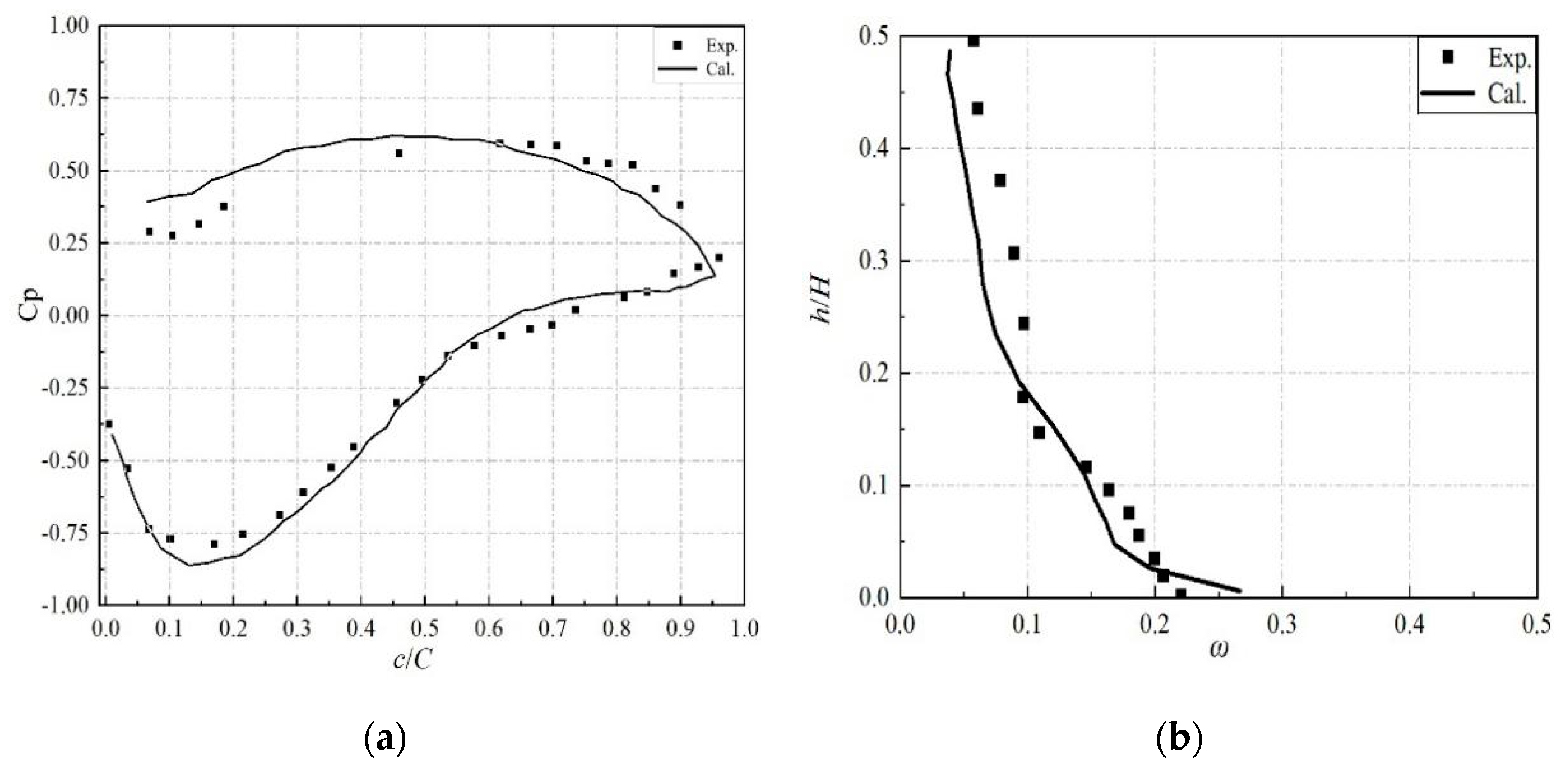
The numerical simulation was validated with experimental results. In this paper, some important flow field parameters that can describe the flow field in the hub corner were tested. Examples of these tests included, the pressure coefficient at the root of the blade, the limiting streamlines on the suction surface of the blade, and the total pressure loss coefficient along the blade height as shown in Figure 1. The numerical results were quite close to experimental results. More experimental details can be seen in [29].
The computational domain started from a distance of 250% axial chord length upstream of the vanes leading edge to 250% axial chord length downstream of the blade trailing edge. A multi-grid O-C-H type mesh was used in the simulations. The computational mesh is shown in Figure 2. The mesh sensitivity analysis showed that the grid sensitivity was negligible, when the total number of mesh was about 1.2 million. In order to eliminate the influence of the mesh topology, the grid used the same topology with different clearances. AutoGrid5 was used to generate the butterfly grid at the trailing edge clearance. The thickness of the mesh wall was 3e-6 m. The cell-centers adjacent to the solid surfaces were located at y+ < 1 for all the computations as shown in Figure 2.
3. Numerical Results
3.1. Vortex Topology in Flow Field
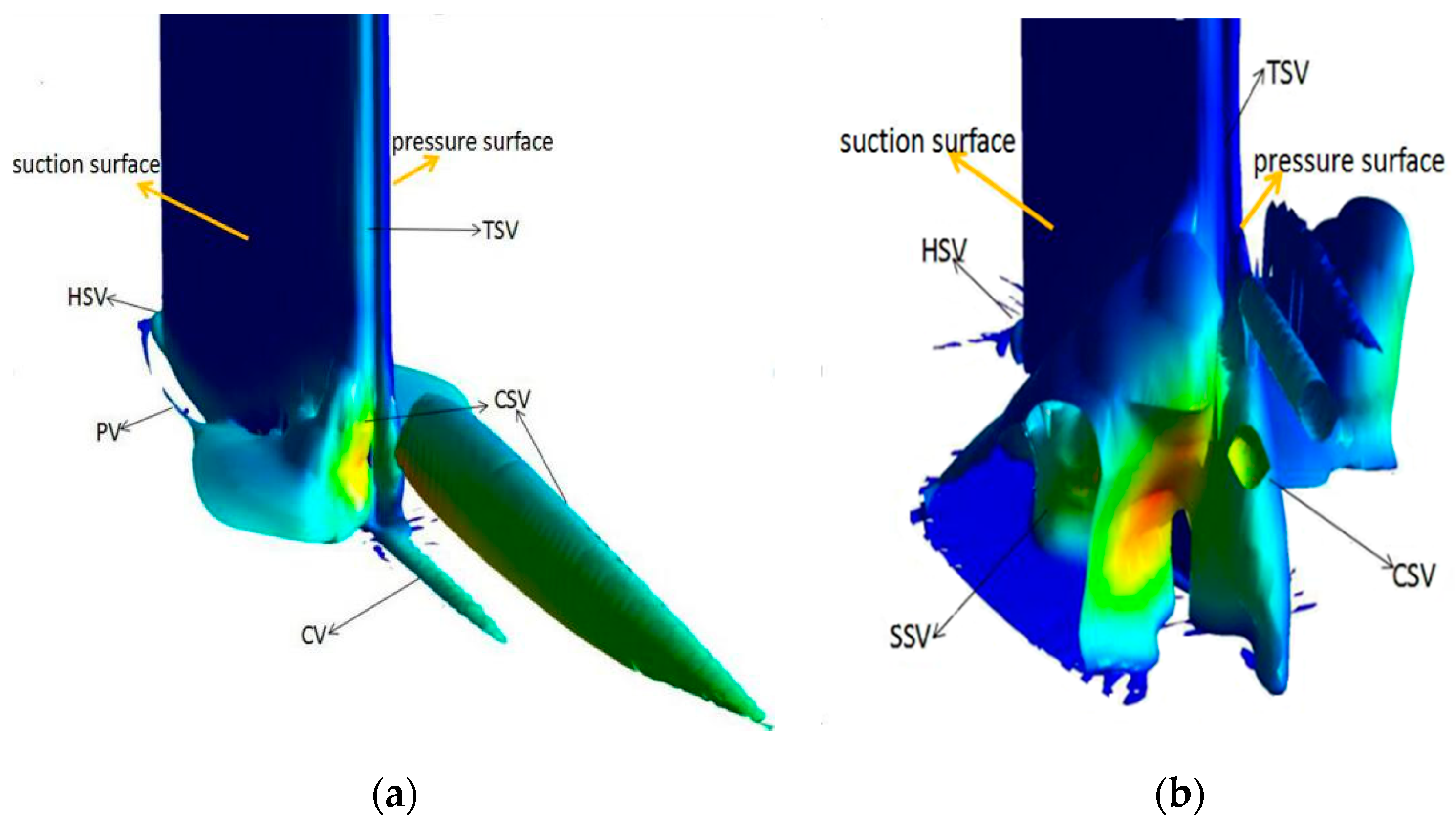
A typical vortex structure diagram is shown in Figure 3. These vortices lead to hub-corner stall at different attack angles. Value of the eddy viscosity is illustrated with variance in color. It is worth mentioning that the Q criterion proposed by Hunt et al. in 1988 is used as a criterion for vortex prediction [30]. Although there are different opinions on the definition of a vortex, it is generally believed that it has two basic requirements: (1) Net vortices exist in the vortex core, (2) the geometry of the vortex core should be Galilean invariant. Considering the above two points, we chose the Q criterion to analyze the vortices. The vortices identified by the Q criterion are in the region where normally the vortices are highly concentrated [31]. The Q criterion can shield the relatively small vortices area better and make the vortex structure clearer.
The vortex structure was very clear in the hub-corner separation as shown in Figure 3a. The horse shoe vortex was divided into two parts: The pressure surface branch and the suction surface branch. The branch of the suction surface dissipated quickly; while the transverse pressures affects the pressure surface gradient and moves toward suction surface, which finally merged into the main channel vortex. When the vortex reached the suction surface, it rolled upward and divided into two parts. One part entered the suction surface boundary layer and moved upward along the blade to form the concentrated shed vortex. The other part continued to grow downstream in the form of a cylindrical vortex after leaving the flow-pass. At the same time, the corner vortex was generated at the junction of the hub and the suction surface. In general, the hub separation means the deflection of the original passage vortex. It is worth highlighting that at this instant, the suction surface boundary layer was affected by the streamwise reverse pressure gradient and the backflow started at very a small range.
Figure 4 shows the transformation of radial vortex from hub-corner separation to hub-corner stall. The fluid flowed from the hub-boundary layer and formed the horse shoe vortex. Later it divided into two branches, one branch of suction surface and one branch of pressure surface. The branch of suction surface was dissipated because of the inverse pressure gradient and induced backflow. The suction surface split the vortex upward and developed along the radial direction. Along the blade span, the separation vortex gradually weakened and disappeared due to the impact of higher momentum mainstream. At the same time, the direction of the vortex axis deviated from the radial direction to the flow direction. The separation vortex continued to rise along the blade and mixed with the trailing radial edge vortex. It became the foundation of the concentrated shed vortex.
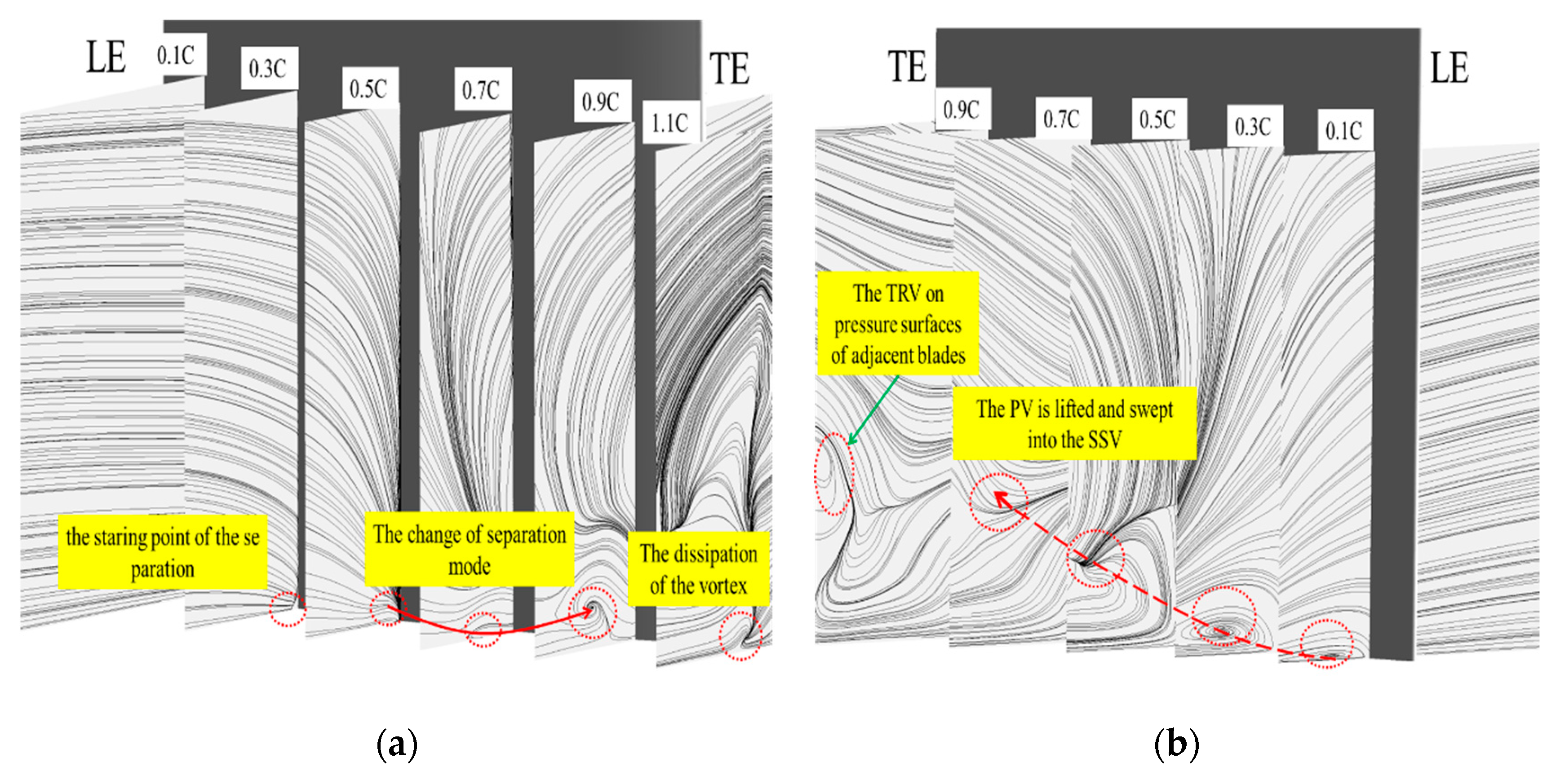
Figure 5 shows the S3 stream spectrum. The distance between the adjacent S3 surfaces is 20% of the chord length. In the Figure 5a flow separation is seen to occur at 0.3 C, which is open separation. Later, the hub layer was rolled up to form a closed suction separation vortex (SSV) and spiral points appeared in the stream spectrum, which completely shaped up at 0.9 C. We can see the position of vortex core in Figure 4b. The flow field was a completely closed separation at trailing edge and it dissipated at 1.1 C. The most obvious vortex structure was the passage vortex (PV) in Figure 5b. The PV developed and moved towards the suction surface of the adjacent blade in the cascades. It mixed with SSV near the hub. The PV disappeared completely and did not affect the flow field any longer at 0.5 C. SSV (Suction Separation Vortex) and TRV (Trailing Radial Vortex) combined to form CSV (Central Shedding Vortex) or we can say CSV was generated due to the blending of SSV and TRV, which influenced the flow field and led to the hub-corner stall. Therefore, if we can control the development of radial vortex in the corner, we can control the hub-corner stall.
3.2. The Trailing Clearances
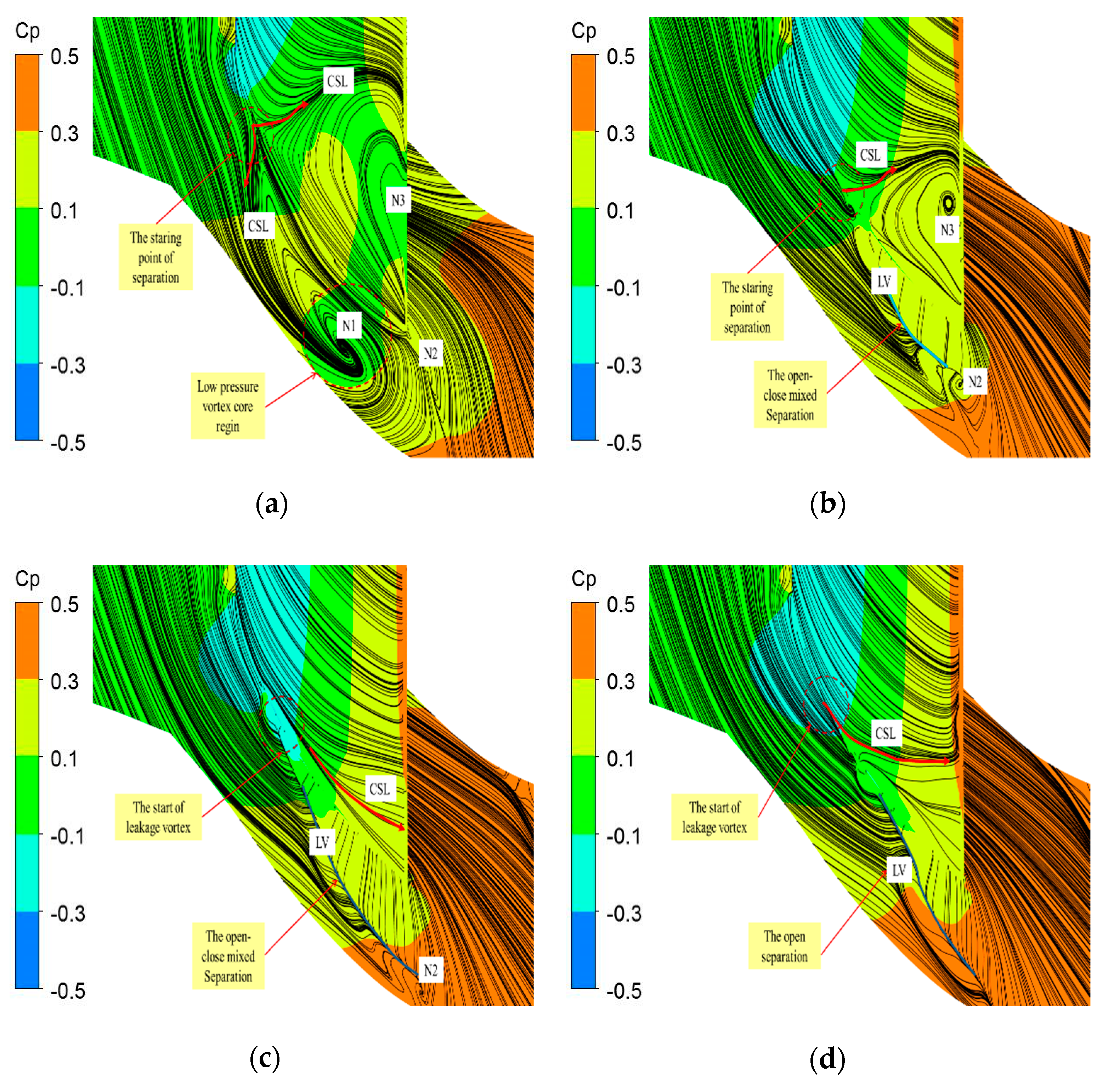
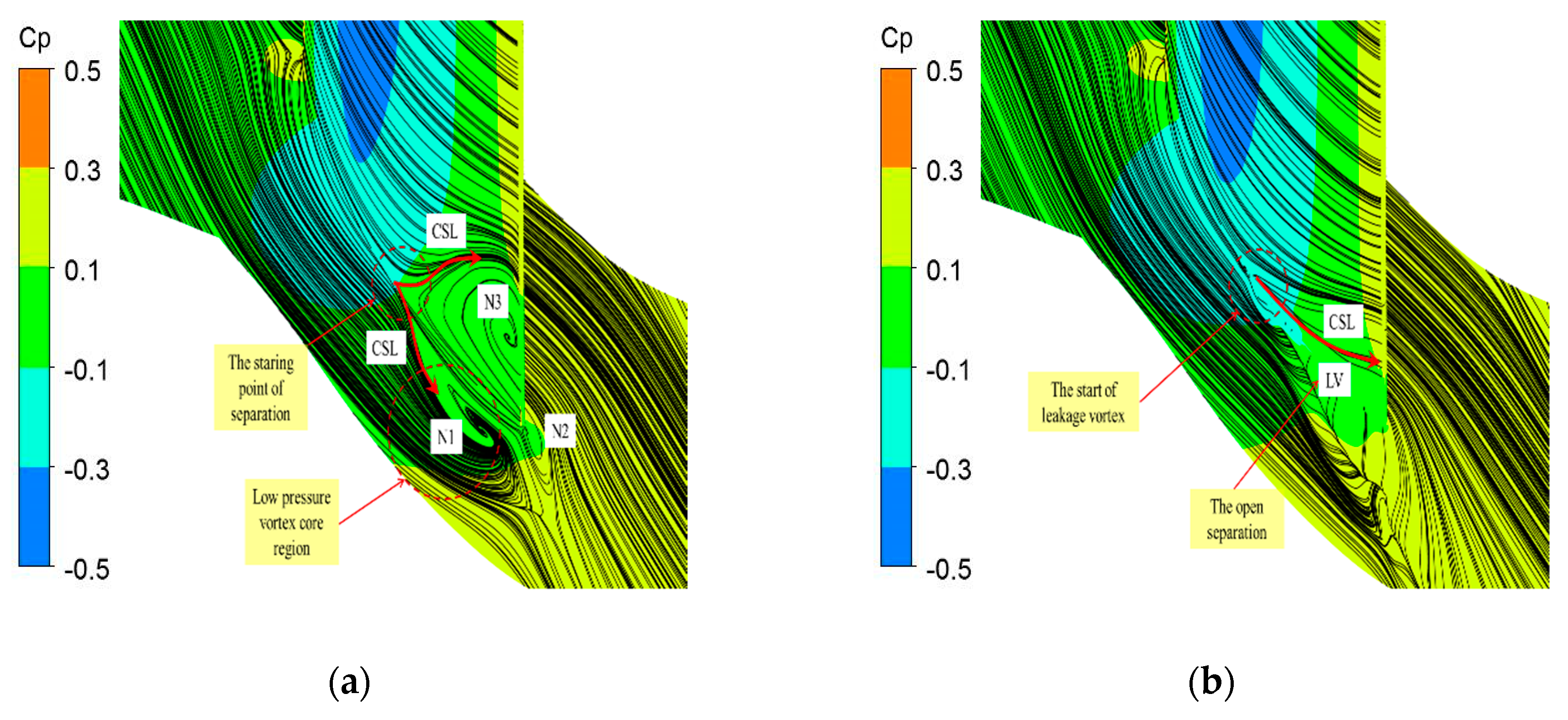
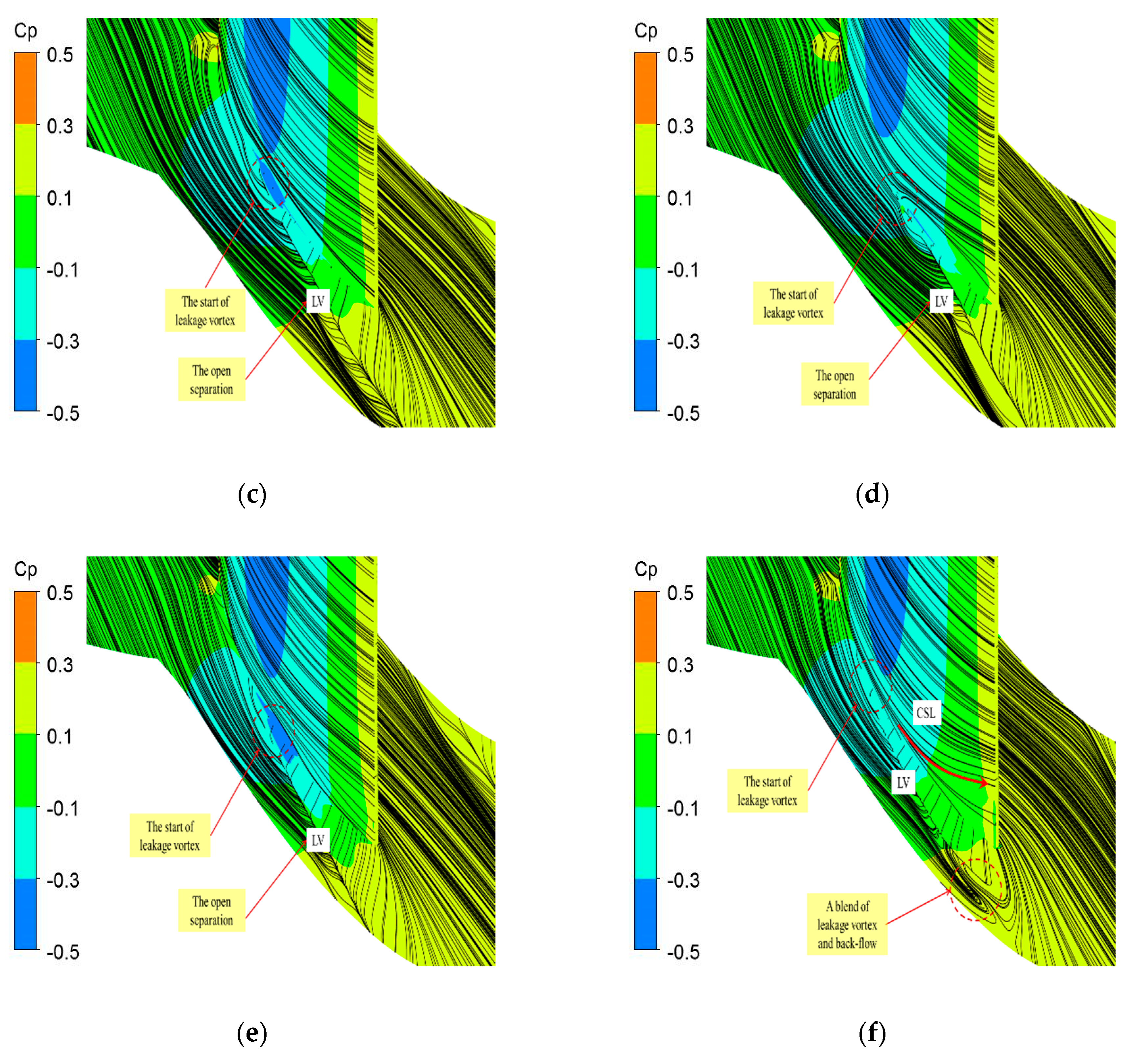
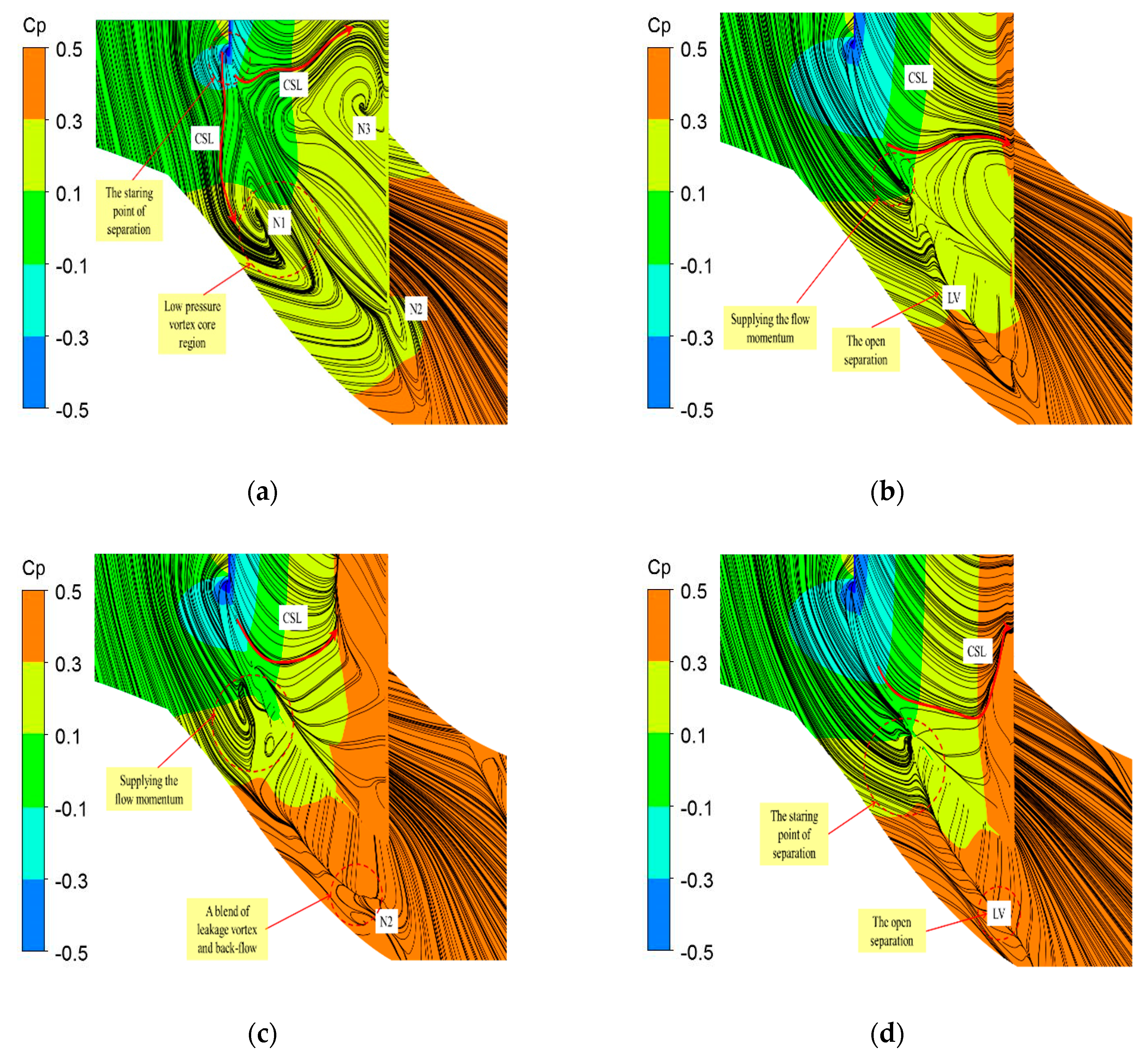
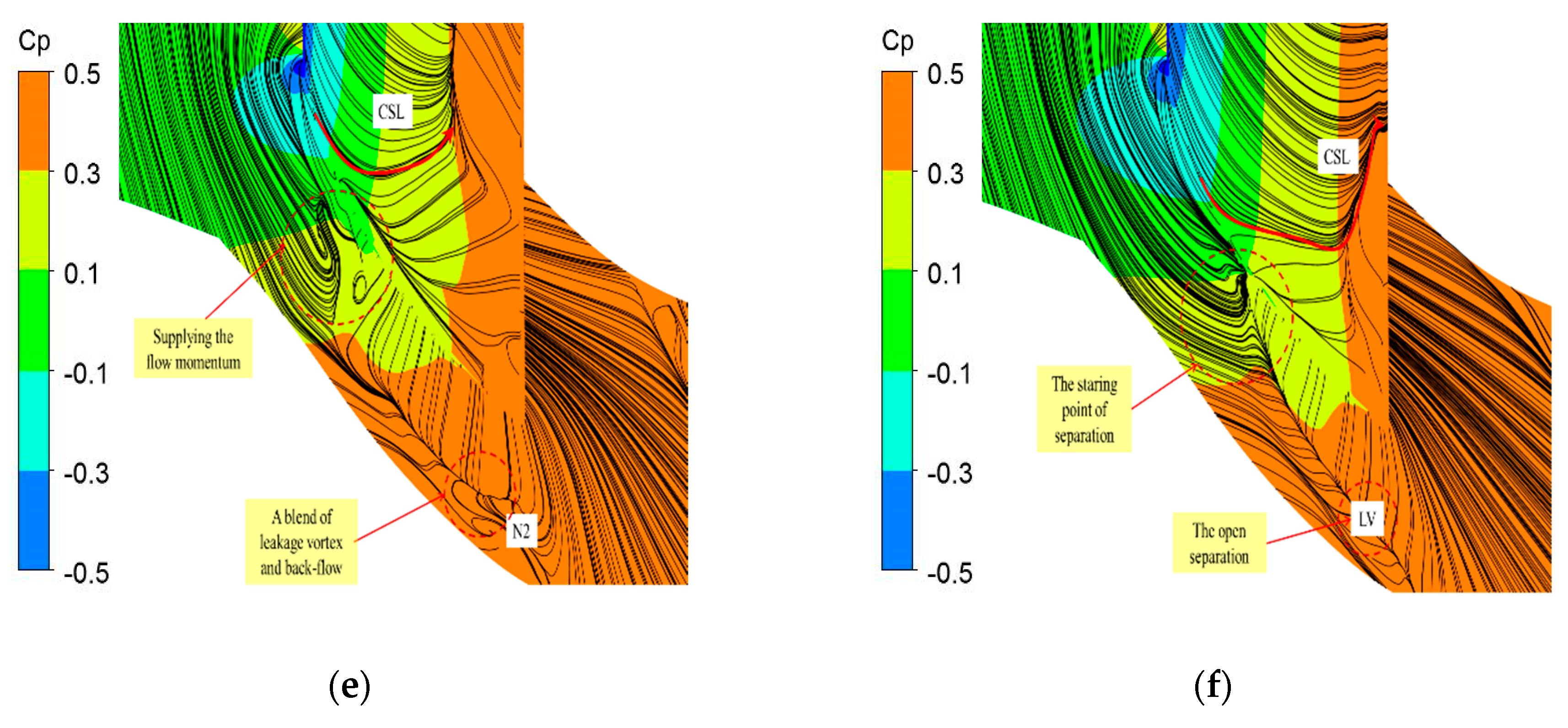
In this paper, five clearances were analyzed in comparison with the baseline cascade. The details are shown in Table 2. Ori means the baseline cascade without clearance. The type of flow separation can be determined from the distribution of limiting streamlines and static pressure coefficient on the suction surface of the blade and hub endwall, as shown in Figure 6.
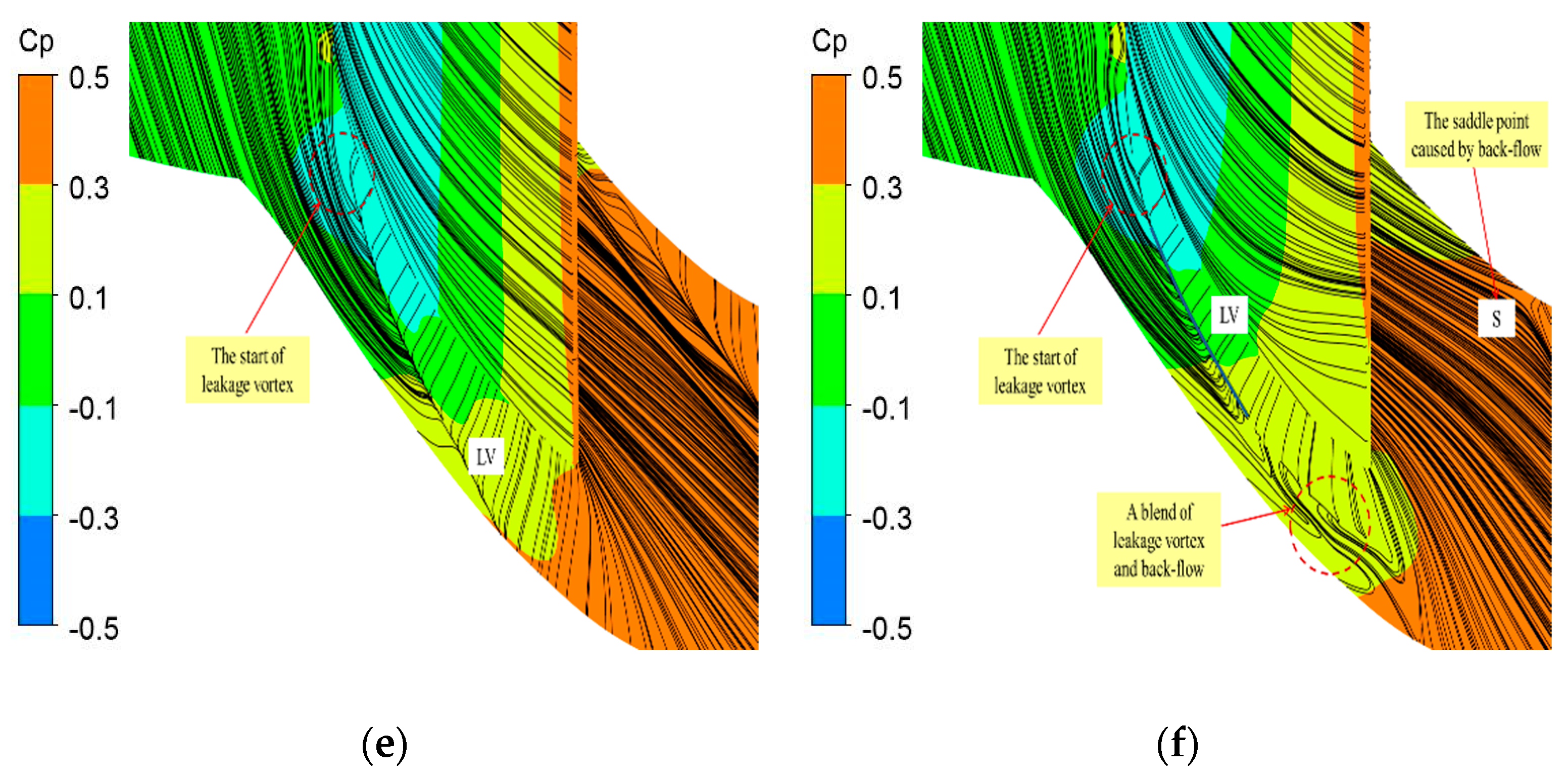
The case 2-0 means case 2 at zero incident. The corner separation lines (CSL) can be seen on the suction surface of the cascades. The endwall boundary layer minimally influenced the mid-span flow field, which was more than that on the near endwall area of the blade. In Figure 6a,b, we can see that the obvious change in flow field due to clearance. In Figure 6a we can see that flow separation occurred at about 0.3 C. Under the inverse pressure gradient, two separation lines appeared at hub and blade. The vortex core of the SSV was located at the low-pressure region of the hub. The fluid, which flowed along the pressure surface, moved around with the trailing edge toward the suction surface. It collided with the boundary layer fluid and mixed with passage vortex. The TRV and SSV developed along the radial direction and moved with the CSV. N1, N2, and N3, as seen in Figure 6 are the vortex core. The closed separation vortex was the main cause of hub-corner stall. In Figure 6b, it can be seen that the SSV was nearly eliminated due to presence of clearance at 0.5 chords. The separation phenomena at the hub changed from the closed separation to the open–close mixed separation due to lack of leakage vortex strength. The TRV still existed (N2), but it was far away from the suction surface. The hub-boundary layer fluid upstream of the clearance turned by the transverse pressure gradient and moved along the blade to form the CSV. In case 2, the clearance length was increased from 0.5 C to 0.7 C. It increased the strength of clearance leakage. The stronger leakage flow boosted the hub-boundary layer fluid momentum in order to resist transverse pressure gradients and prevent transverse transport of the boundary layer. Subsequently, the closed separation turned to the open separation in the corner and the CSV disappeared. In case 3 the height was higher than case 1, but the effect on the CSV was not as good as that of case 2, which had longer clearance. It indicated that the length of the trailing edge played a more important role in controlling the CSV. The cascade used in this paper had a lower turning angle. It can be approximated that the clearance flow area between case 2 and case 3 was the same i.e., height*length. In Case 3, the backflow disappeared at the trailing edge of the blade. This shows that the height of trailing edge had greater effect on trailing edge backflow. Case 4 and case 5 comprised of 100% chord length clearance with different height. It has been observed that the full clearances can totally eliminate the CSV. Moreover, the separation at suction surface of blade was eliminated. The clearance height of Case 5 was smaller than all the clearances in this paper. Consequently, all the vortex structures mentioned above can be seen in the flow field of Case 5. It is worth mentioning that in the full clearance, the starting point of the leakage flow was not at the leading edge of the blade, so the full clearance was not beneficial for the flow field.
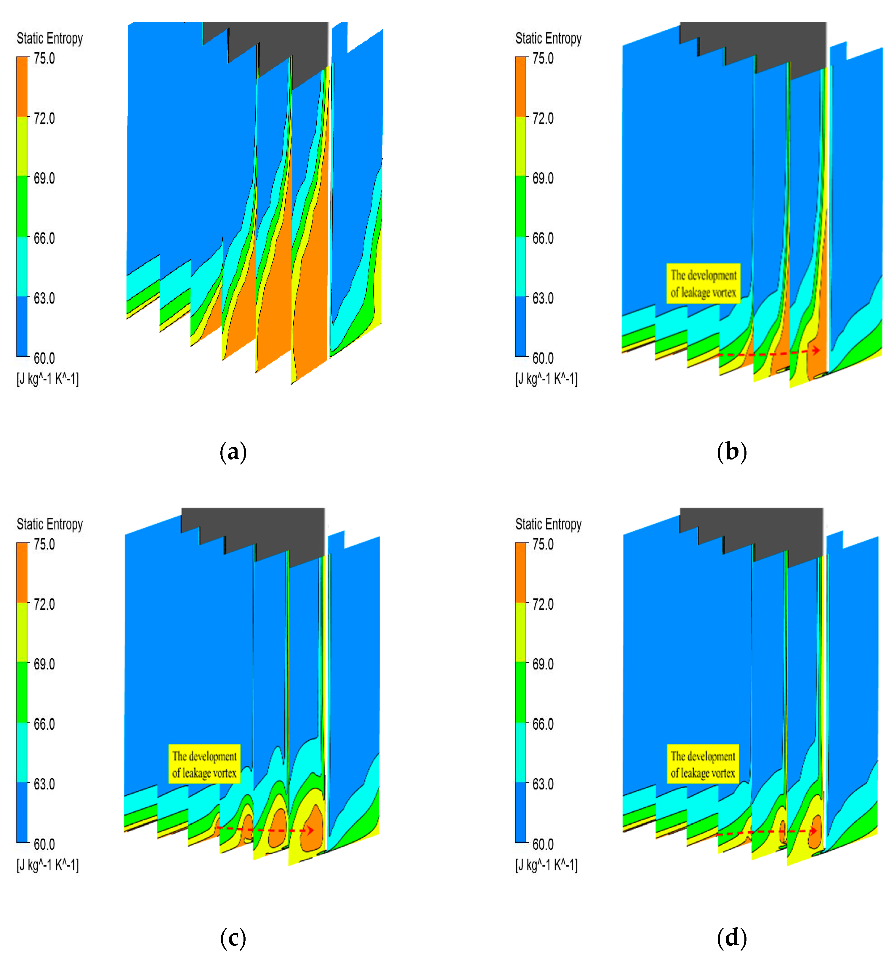
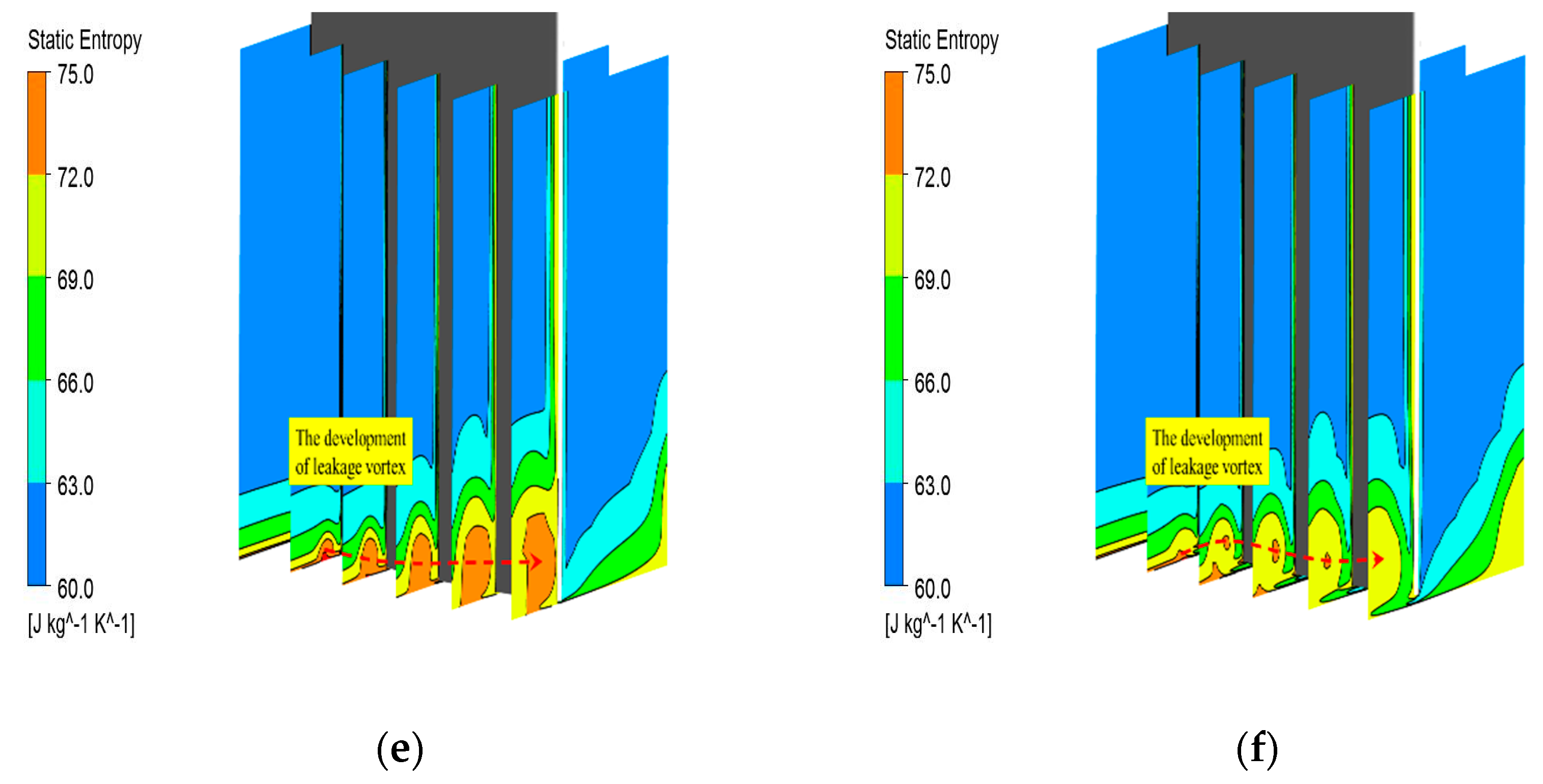
Figure 7 shows the static entropy contours at hub corner of all cases. The adverse pressure gradient and the transverse pressure gradient influenced the 3-D streamlines in the flow direction and forced its movement towards the middle span of the blade. With the influence of the clearance, the high entropy region at the hub corner gradually became smaller and eventually disappeared. It can be seen by comparing Figure 7c,d that the longer clearance will cause higher losses at the corner at constant flow area of the clearance. The velocity of clearance leakage can be divided into flow velocity and transverse velocity. The flow velocity increased the flow momentum of the hub-boundary layer in order to avoid flow separation and suppressed radial vortex development. While the transverse velocity increased the transverse momentum of the hub-boundary layer, which hindered the mainstream and generated leakage loss.
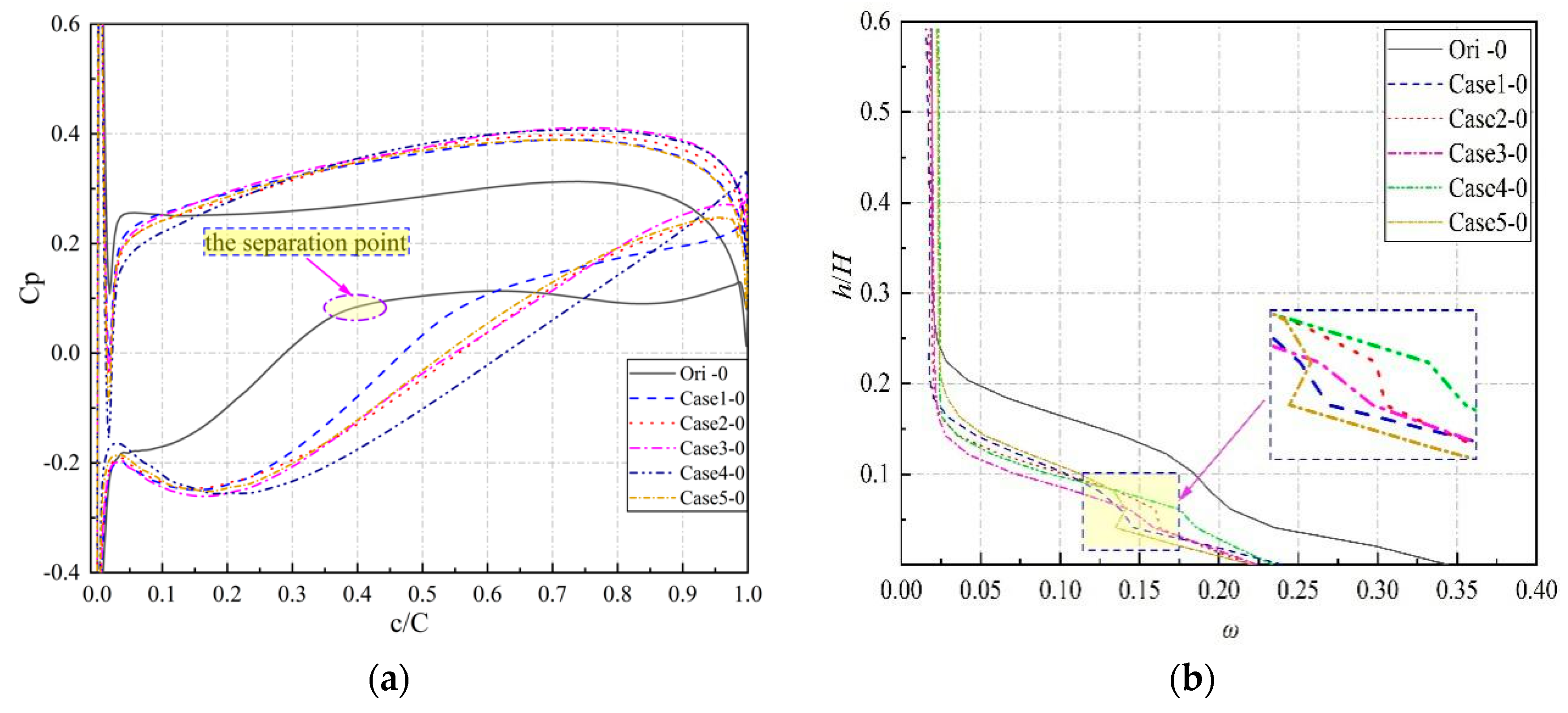
Quantitative analysis of the control effect and cascade performance was analyzed for each flow control method. In this paper, the static pressure coefficient was used to characterize the control effect of clearance on the flow field and the total pressure loss coefficient characterized cascade performance. The total pressure loss and static pressure with i = 0 is shown in Figure 8. In the Figure 8a, the flow around the suction surface of the prototype cascade was mainly closed separation. Therefore, the pressure coefficient increased slowly and partially decreased in the latter half of the suction surface. It indicates that the pressure diffusion capability was disappearing due to the serious separation. It was observed that with the clearance in the cascade, the diffuser capacity was gradually restored. Furthermore, with the disappearance of the closed separation, the cascade gained the ability of re-diffusion. This ability varied with the size of the clearance. The separation did not eliminate completely, however, and the separation pattern was changed. The suction surface branch of Ori-0 (the prototype cascade) had a turning point at 40% chord (0.4 C), which was the separation point in the flow field. Case 1 delayed the separation position to 0.6 C, but it could not completely eliminate the SSV. However, the other clearances i.e., case 2 to 5 completely eliminated the SSV formed by the hub-corner stall. Case 4 i.e., the full clearance gave the best effect. It can be seen from Figure 8b that different clearance structures significantly reduced the loss of cascade. On the one hand, case 3 had enough height to eliminate SSV and TRV compared to case 1. On the other hand, case 3 did not lead to large leakage loss as seen in case 2. Therefore, case 3 had the best effect among the clearances. Case 4 had the best control effect on stall elimination at the hub corner. However, it had the highest leakage loss. The pressure contours in Figure 6 show that the trailing edge clearances reduced the thickness of the boundary layer, and thus improved the separation resistance of the boundary layer in order to reduce the cascade loss. At the same time, the trailing edge clearance disturbed the pressure and velocity fields in the separation zone, so that the saddle point could not be formed at the root of the suction surface. The saddle point was the necessary condition for the formation of closed separation. The trailing edge clearances not only inhibited the separation in the hub corner, but also had the minimum leakage loss at design point.
The ability to operate under all working conditions is an essential requirement of actual compressor stator blades. For the implementation of passive control technology, it is quite important that compressor should be able to operate in stable region at lower mass flow rates and its design efficiency should not be reduced. Therefore, the analysis of flow field at off-design point is also an essential requirement. The flow spectrum of cascade at i = −6 is shown in the Figure 9.
It can be seen that the trailing edge clearance was also very effective in controlling the flow field at the negative angle of attack. The accumulation of low energy fluid in the hub corner was almost same as in the design point. The strength of the TRV, SSV, and CRV was much smaller than design point. Three trailing edge clearances eliminated the low energy fluid in the corner well and controlled the backflow. The trailing edge clearance completely eliminated the flow separation at the suction side at 70% chord. It allowed the root of the blade to achieve re-diffusion as shown in Figure 10a. It is noteworthy that the total pressure loss, with full clearance at 5% blade height, was higher in comparison with trailing edge clearances. This loss was generated by the open separation at the blade root. This was an identical trend as demonstrated in the design point flow field. Hence, the trailing edge clearances did not produce additional leakage loss at the negative attack angle.
Compressor stall margin is an important parameter in analysis of compressor performance. The flow at higher angle of attack was simulated in order to study actual compressor near stall condition. At higher angle of attack, the separation position on the suction surface moved further ahead at 27% chord as shown in Figure 11a. The strength of the TRV and CRV increased. The flow separation on the suction surface occurred at the leading edge of the cascade. The total pressure loss and diffusion of case 2 and case 3 were almost the same because the clearance flow area was similar. The control effect of case 3 was better at i = +6. In case 2 separation vortex could not be eliminated on suction surface because the length of clearance in case 2 was longer. The transverse velocity of leakage flow was higher. Higher transverse velocity could only disperse the separated vortex but it could not completely suppress the stall. In case 3 the height of clearance was higher than others. It generated high velocity flow to shift the momentum of flow toward low energy fluid at the hub. In comparison to clearance length, the height of the clearance with the identical flow area had higher influence in order to control hub-corner stall. Figure 12 validates this judgment. The full clearance had the best control effect on the stall in the corner area. It completely eliminated the separation vortex in the corner. However, in this case, the leakage loss of the flow field was higher in comparison with case 3, which had a greater impact on the rotor blade of the rear stages.
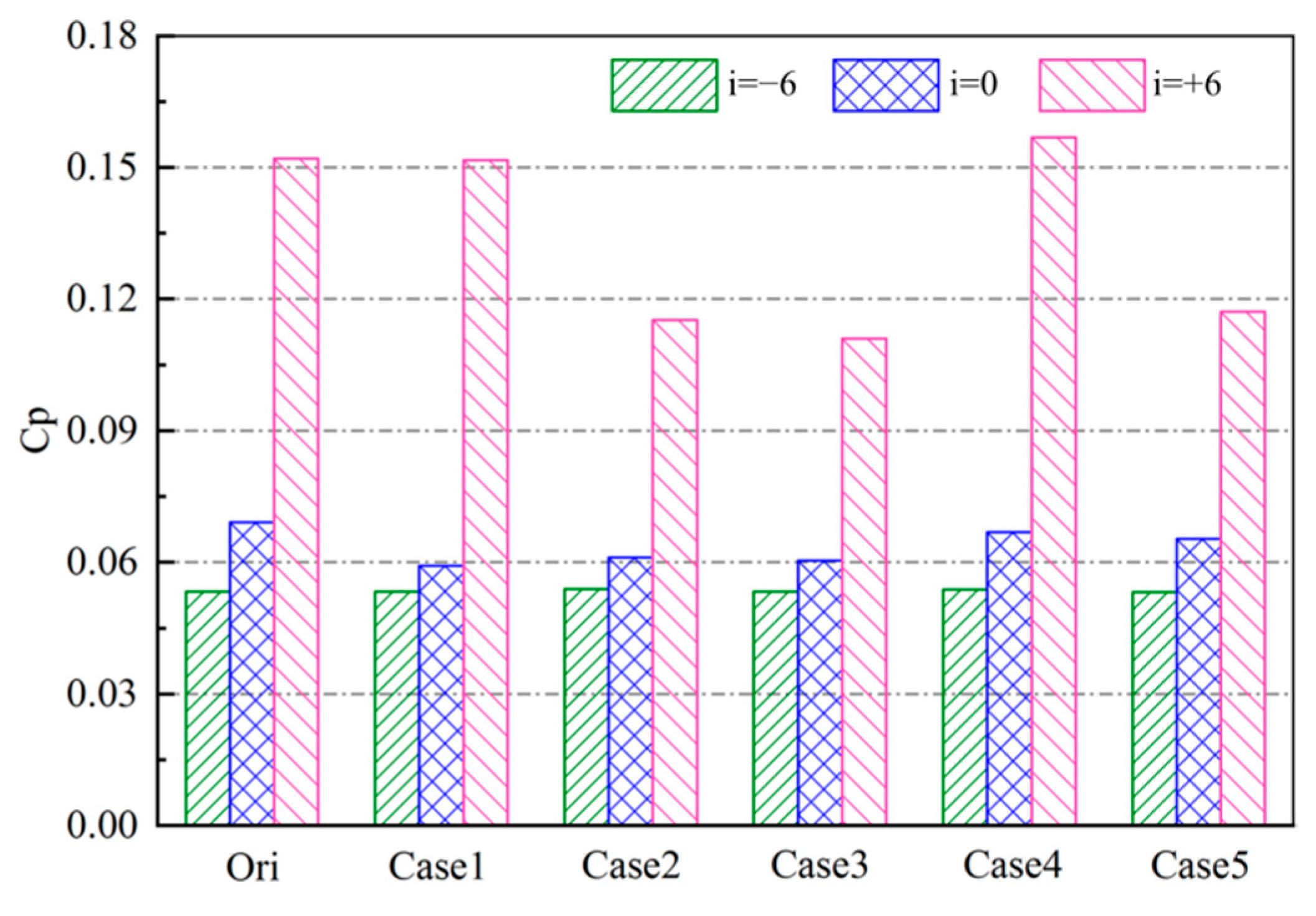
The trailing edge clearance reduced the total pressure loss of cascades under all working conditions as shown in Figure 13. The effect of proper trailing edge clearance on flow field was more obvious in case 3, when the attack angle was not less than zero. In contrast, the full clearance caused greater leakage loss at the positive incidence as in case 4. At the negative angle of attack, the trailing edge clearance did not cause additional leakage loss in the flow field. It can be seen from Figure 13 that the trailing edge clearance caused the cascades to achieve a higher stall attack angle. This means that cascade had better performance at higher angle of attack. Hence, the trailing edge clearance allowed the compressor stator to work steadily at a higher angle of attack.
Table 3 shows the changing of on-total pressure loss with clearances at variable angles of attack compared with the prototype cascade. Higher clearance (case 3) can greatly reduce the loss of flow field under all working conditions. The positive angle of attack increased the blade load and the surface pressure difference, which led to stronger gap leakage flow and greater total pressure loss. Clearance height had a better effect in controlling the hub-corner stall in comparison to length at constant flow area.
4. Discussion and Conclusions
The vortices structure in the stall flow field was obtained in this paper through the numerical simulation of variable angle of attack in the cascade. We conclude the following:
- Hub-corner stall comprises three main vortices: SSV, TRV, and CRV. They are generated due to effect of backflow and radial movement of hub-surface boundary layer. Therefore, hub-corner stall can be eliminated by controlling the separation of the hub-boundary layer. The trailing edge clearance can restrain the boundary layer separation on the suction surface and acquire the ability of re-diffusion at the hub corner.
- By comparing the trailing edge clearance with the full clearance, it was observed that both types of clearance can eliminate the radial vortex and inhibit the occurrence and development of hub-corner stall. However, the trailing edge clearances not only can inhibit the separation in the hub corner but also have the minimum leakage loss at design point. The trailing clearances are lower cost and more effective than the traditional full clearances.
Among two control parameters of the trailing edge clearance i.e., length and height, length is more influential in controlling the transverse transport of the hub-surface boundary layer in the corner (CSV). Height is more influential in controlling fluid backflow and its radial development. When the clearance flow area is approximately identical, having more height is better for the loss and stall margin of the clearance. The clearance leakage flow generated by higher clearance has higher flow momentum at the hub-boundary layer and it avoids flow separation. The leakage flow generated by the lengthy clearance has stronger transverse momentum in order to avoid transverse transport of the hub-boundary layer.
Compared with the previous uniform clearance, the trailing edge clearance does not cause greater leakage loss to the cascade at the design of point of the flow field. At the same time, compared with the active control method, the trailing edge clearance is easy to process, and no additional control equipment is needed in the compressor. The control technology of trailing edge clearance has lower cost and better effect.
Author Contributions
Conceptualization, W.Z. and Q.Z.; Methodology, W.Z.; Software, W.Z. and B.J.; Validation, W.Z.; Formal Analysis, W.Z.; Investigation, W.Z.; Resources, W.Z. and B.J.; Writing-Original Draft Preparation, W.Z. and A.M.; Writing-Review and Editing, W.Z. and A.M.; Visualization, Q.Z.; Supervision, B.J.; Project Administration, W.Z.
Funding
This research was funded by The National Natural Science Foundation of China, grant number NO.5167605.
Conflicts of Interest
The authors declare no conflict of interest.
Abbreviations
| CSV | Central Shedding Vortex |
| TRV | Trailing Radial Vortex |
| SSV | Suction Separation Vortex |
| Cp | Pressure coefficient |
| CSL | Corner separation line |
References
- Liesner, K.; Meyer, R. Evaluation of passive and active secondary flow control in a high speed compressor Cascade with Different Measurement Techniques. In New Results in Numerical and Experimental Fluid Mechanics VIII; Springer: Berlin/Heidelberg, Germany, 2013. [Google Scholar]
- Kang, S.; Hirsch, C. Three dimensional flow in a linear compressor cascade at design conditions. In Proceedings of the ASME 1991 International Gas Turbine and Aeroengine Congress and Exposition, Orlando, FL, USA, 3–6 June 1991. ASME Paper No. 91-GT-114. [Google Scholar]
- Hah, C.; Loellbach, J. Development of hub corner stall and its influence on the performance of axial compressor Blade Rows. J. Turbomach. 1999, 121, 67–77. [Google Scholar] [CrossRef]
- Lei, V.M.; Spakovszky, Z.S.; Greitzer, E.M. A criterion for axial compressor Hub-Corner Stall. J. Turbomach. 2008, 130, 031006. [Google Scholar] [CrossRef]
- Schulz, H.D.; Gallus, H.E. Experimental investigations of the three-dimensional flow in an annular compressor cascade. J. Turbomach. 1988, 110, 467–478. [Google Scholar] [CrossRef]
- Williamson, C.; Weierman, J.; Jacob, J. Flow control in an axial compressor using plasma actuators. In Proceedings of the 39th AIAA Fluid Dynamics Conference, Fluid Dynamics and Co-located Conferences, San Antonio, TX, USA, 22–25 June 2009. [Google Scholar]
- Qiushi, L.I.; Simin, L.I.; Pan, T. Effects of the radial blade loading distribution and B, parameter on the type of flow instability in a low-speed axial compressor. Chin. J. Aeronaut. 2018, 31, 1470–1479. [Google Scholar]
- Antonia, R.A.; Zhu, Y.; Sokolov, M. Effect of concentrated wall suction on a turbulent boundary layer. Phys. Fluids 1995, 7, 2465–2474. [Google Scholar] [CrossRef]
- Schobeiri, M.T.; Attia, M. Active control of compressor instability and surge by stator blades adjustment. J. Propul. Power 2015, 19, 312–317. [Google Scholar] [CrossRef]
- Larosiliere, L.M.; Wood, J.R.; Hathaway, M.D.; Medd, A.J.; Dang, T.Q. Aerodynamic Design Study of Advanced Multistage Axial Compressor; NASA-TP 2002-211568, ARL-TR-2859; NASA Glenn Research Center: Cleveland, OH, USA, 2002.
- Linder, C.G. Single-Stage Experimental Evaluation of Variable Geometry Guide Vanes and Stators. Part II Annular Cascade Investigations of Candidate Variable Geometry Designs; US NASA CR-54555; NASA: Washington, DC, USA, 1997.
- Serovy, G.K.; Kavanagh, P. Considerations in the Design of Variable-Geometry Blading for Axial-Flow Compressor Stages; NATO Advisory Group for Aerospace Research and Development, AGARD CP: Neuilly sur Seine, France, 1968; Volume 34. [Google Scholar]
- Johnson, M.C.; Greitzer, E.M. Effect of slotted hub and casing treatment on compressor endwall flow field. J. Turbomach. 1987, 109, 380–387. [Google Scholar] [CrossRef]
- Smith, G.D.J.; Cumpsty, N.A. Flow phenomena in compressor casing treatment. J. Eng. Gas Turbines Power 1984, 106, 532–541. [Google Scholar] [CrossRef]
- Brookfield, J.M.; Waitz, I.A. Trailing edge blowing for reduction of turbomachinery Fan Noise. In Proceedings of the 4th AIAA/CEAS Aeroacoustics Conference, Toulouse, France, 2–4 June 1998. AIAA Paper 98-2321. [Google Scholar]
- Xu, W.; Du, X.; Wang, S. Correlation of solidity and curved blade in compressor cascade design. Appl. Therm. Eng. 2018, 131, 244–259. [Google Scholar] [CrossRef]
- Zhao, G.; Chen, F.; Song, Y. Optimization design of compressor cascade with swept and curved blades. In Proceedings of the 43rd AIAA Aerospace Sciences Meeting and Exhibit, Reno, NV, USA, 10–13 January 2005. [Google Scholar]
- Li, Y.; Zhou, S.Q.; Wang, J.; Li, H.; Fu, G.J.; Foshan, C.N. Analysis of Aerodynamic Noise of a Swept-Curved Axial Flow Fan With Different Rotate Speed. J. Eng. Thermophys. 2014, 35, 51–55. [Google Scholar]
- Lin, A.; Sun, Y.; Zhang, H.; Lin, X.; Yang, L.; Zheng, Q. Fluctuating characteristics of air-mist mixture flow with conjugate wall-film motion in a compressor of gas turbine. Appl. Therm. Eng. 2018, 142, 779–792. [Google Scholar] [CrossRef]
- Chen, G.T.; Greitzer, E.M.; Tan, C.S.; Marble, F.E. Similarity Analysis of Compressor Tip Clearance Flow Structure. J. Turbomach. 1991, 113, 260–271. [Google Scholar] [CrossRef]
- Hah, C. A numerical modeling of endwall and tip-clearance flow of an isolated compressor rotor. J. Eng. Gas Turbines Power 1986, 108, 15–21. [Google Scholar] [CrossRef]
- Zhong, J.J.; Wu, W.-Y.; Wang, H.S. Effect of blade tip winglet on aerodynamic performance of high subsonic compressor cascade at different tip clearances. J. Eng. Thermophys. 2018, 39, 757–766. [Google Scholar]
- Lee, C.; Song, J.; Lee, S.; Hong, D. Effect of a clearance between Inner casing and stator blade on axial compressor performance. In Proceedings of the ASME Turbo Expo 2010: Power for Land, Sea, and Air, Glasgow, UK, 14–18 June 2010. [Google Scholar]
- Gbadebo, S.A.; Cumpsty, N.A. Interaction of tip clearance flow and three-dimensional separations in axial compressors. J. Turbomach. 2007, 129, 679–685. [Google Scholar] [CrossRef]
- Zuo, Z.T.; Zhu, Y.L.; Zhang, D.Y.; Tan, C.Q. Numerical investigation of the stator hub clearance effects on aerodynamic performance of a high-pressure compressor. J. Propul. Technol. 2011, 32, 329–333. [Google Scholar]
- Ribi, B.; Meyer, M.P. Influence of a Clearance between Casing and Variable Stator Blade on Axial Compressor Performance; ASME Paper GT-2008-50301; ASME: New York, NY, USA, 2008. [Google Scholar]
- Xu, W.-F.; Peng, S.; Zhong, J.J.; Huang, L.S. Numerical study for the influence of stator tip clearance height on compressor performance. J. Dalian Marit. Univ. 2017, 43, 63–70. [Google Scholar]
- Zhao, W.; Jiang, B.; Zheng, Q. Control of the corner separation in a linear cascade by trailing clearances. In Proceedings of the ASME Turbo Expo 2017: Turbomachinery Technical Conference and Exposition, Charlotte, NC, USA, 26–30 June 2017; p. V02AT39A043. [Google Scholar]
- Guo, S. Investigation on Aerodynamic Performance of High-Camber-Angle Compressor Cascades with Boundary Layer Suction. Ph.D Thesis, Harbin Institute of Technology, Harbin, China, 2011. [Google Scholar]
- Le, C. Investigation on Separation Structure and Its Steady & Unsteady Control in Super Highly Loaded Compressor Cascade. Ph.D Thesis, Harbin Institute of Technology, Harbin, China, 2015. [Google Scholar]
- Kan, X. Research of Three-Dimensional Vortex Structure in a Transonic Compressor Stator. Ph.D Thesis, Dalian Maritime University, Dalian, China, 2016. [Google Scholar]
Figure 1.
Comparison between numerical calculation and experimental results: (a) The blade loading at 5% H; (b) The total pressure loss at 5% H.
Figure 1.
Comparison between numerical calculation and experimental results: (a) The blade loading at 5% H; (b) The total pressure loss at 5% H.

Figure 2.
Computational mesh and y+ (a) Computational mesh of the stator; (b) The trailing edge gap; (c) The distribution of y+ on solid walls.
Figure 2.
Computational mesh and y+ (a) Computational mesh of the stator; (b) The trailing edge gap; (c) The distribution of y+ on solid walls.

Figure 3.
Vortex structure in hub corner (a) Topology of corner separation (i = −6); (b) Topology of corner stall (i = 0).
Figure 3.
Vortex structure in hub corner (a) Topology of corner separation (i = −6); (b) Topology of corner stall (i = 0).

Figure 4.
Three-dimensional flow in hub corner (a) Hub-corner separation (i = −6); (b) Hub-corner stall (i = 0).
Figure 4.
Three-dimensional flow in hub corner (a) Hub-corner separation (i = −6); (b) Hub-corner stall (i = 0).

Figure 5.
The development of vortex in flow direction. (a) The streamlines of the suction surface in S3; (b) The streamlines of the pressure surface in S3.
Figure 5.
The development of vortex in flow direction. (a) The streamlines of the suction surface in S3; (b) The streamlines of the pressure surface in S3.

Figure 6.
Static pressure contour/limiting streamlines (i = 0) (a) Ori-0; (b) Case 1-0; (c) Case 2-0; (d) Case 3-0; (e) Case 4-0; (f) Case 5-0.
Figure 6.
Static pressure contour/limiting streamlines (i = 0) (a) Ori-0; (b) Case 1-0; (c) Case 2-0; (d) Case 3-0; (e) Case 4-0; (f) Case 5-0.


Figure 7.
Static entropy contours at hub corner (i = 0) (a) Ori-0; (b) Case 1-0; (c) Case 2-0; (d) Case 3-0; (e) Case 4-0; (f) Case 5-0.
Figure 7.
Static entropy contours at hub corner (i = 0) (a) Ori-0; (b) Case 1-0; (c) Case 2-0; (d) Case 3-0; (e) Case 4-0; (f) Case 5-0.


Figure 8.
Total pressure loss and static pressure (i = 0). (a) Static pressure coefficient at 5% H; (b) Total pressure loss along blade span.
Figure 8.
Total pressure loss and static pressure (i = 0). (a) Static pressure coefficient at 5% H; (b) Total pressure loss along blade span.

Figure 9.
Static pressure contour/limiting streamlines (i = −6). (a) Ori-−6; (b) Case 1-−6; (c) Case 2-−6; (d) Case 3-−6; (e) Case 4-−6; (f) Case 5-−6.
Figure 9.
Static pressure contour/limiting streamlines (i = −6). (a) Ori-−6; (b) Case 1-−6; (c) Case 2-−6; (d) Case 3-−6; (e) Case 4-−6; (f) Case 5-−6.


Figure 10.
Total pressure loss and static pressure (i = −6). (a) Static pressure coefficient at 5% H; (b) Total pressure loss along blade span.
Figure 10.
Total pressure loss and static pressure (i = −6). (a) Static pressure coefficient at 5% H; (b) Total pressure loss along blade span.
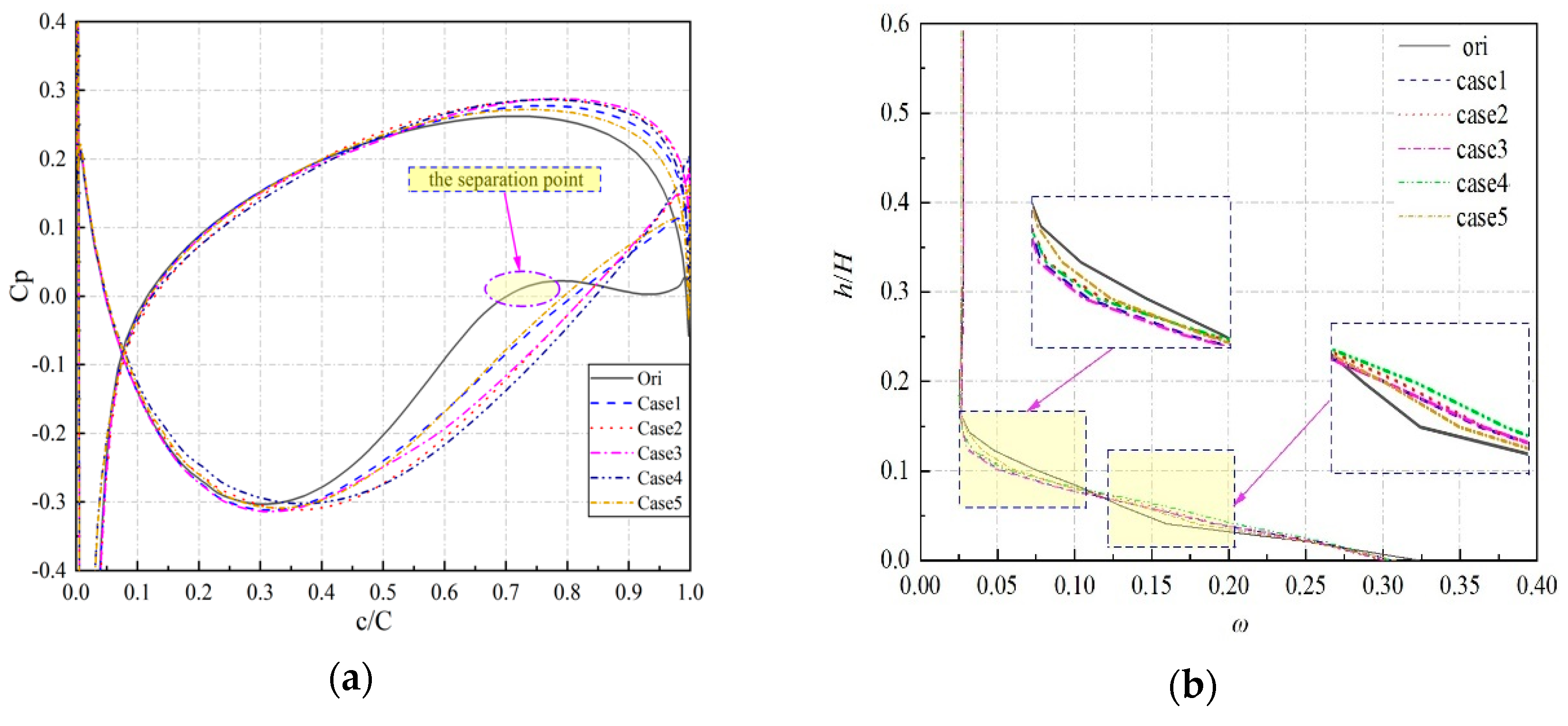
Figure 11.
Static pressure contour/limiting streamlines (i = +6). (a) Ori-+6; (b) Case 1-+6; (c) Case 2-+6; (d) Case 3-+6; (e) Case 4-+6; (f) Case 5-+6.
Figure 11.
Static pressure contour/limiting streamlines (i = +6). (a) Ori-+6; (b) Case 1-+6; (c) Case 2-+6; (d) Case 3-+6; (e) Case 4-+6; (f) Case 5-+6.


Figure 12.
Total pressure loss and static pressure (i = −6). (a) Static pressure coefficient at 5% H; (b) Total pressure loss along blade span.
Figure 12.
Total pressure loss and static pressure (i = −6). (a) Static pressure coefficient at 5% H; (b) Total pressure loss along blade span.
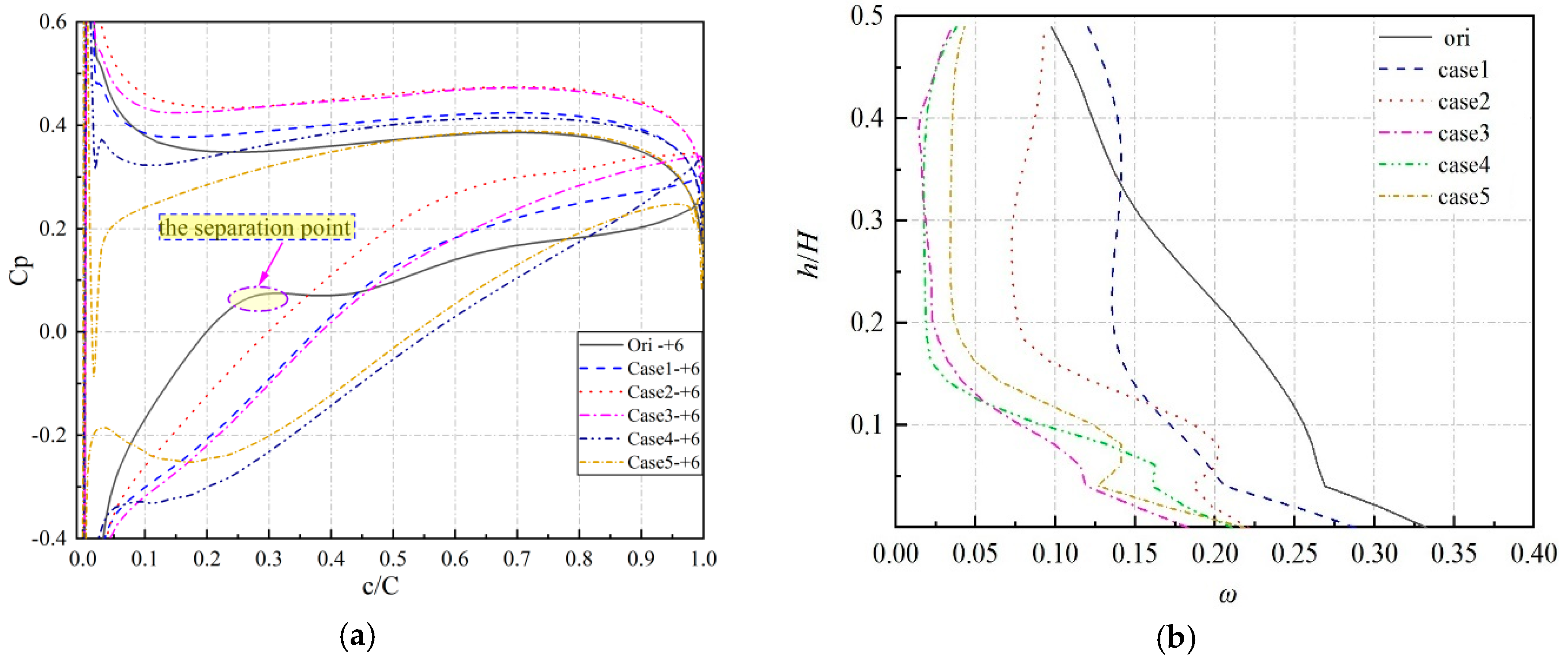
Figure 13.
Total pressure loss for all the cases.

Table 1.
Cascade design parameters and test conditions (stator).
| Parameter | Variable | Value | Unit |
|---|---|---|---|
| Chord length | C | 70 | mm |
| Blade span | H | 160 | mm |
| Blade pitch | t | 54.59 | mm |
| Solidity | C/t | 1.283 | - |
| Turn angle | θ | 20 | ° |
| Incident angle | i | 0, ±2, ±4, ±6 | ° |
| Inlet Mach number | Ma | 0.3 | - |
| Diffusion factor | D | 0.5 | - |
Table 2.
Clearance parameters.
| Parameter | Ori | Case 1 | Case 2 | Case 3 | Case 4 | Case 5 |
|---|---|---|---|---|---|---|
| Length (l/C) | 0 | 0.5 | 0.7 | 0.5 | 1 | 1 |
| Height (h/H) | 0 | 0.3 | 0.3 | 0.4 | 0.4 | 0.15 |
Table 3.
Effect of clearance on total pressure loss.
| Incident | Case 1 | Case 2 | Case 3 | Case 4 | Case 5 |
|---|---|---|---|---|---|
| −6 | −0.13% | +1.01% | −0.03% | −0.09% | −0.84% |
| 0 | −13.7% | −11.7% | −19.6% | −3.8% | −5.5% |
| +6 | −0.2% | −24.2% | −27.0% | +3.2% | −22.0% |
© 2019 by the authors. Licensee MDPI, Basel, Switzerland. This article is an open access article distributed under the terms and conditions of the Creative Commons Attribution (CC BY) license (http://creativecommons.org/licenses/by/4.0/).
Share and Cite
MDPI and ACS Style
Zhao, W.; Zheng, Q.; Malik, A.; Jiang, B. The Effect of Trailing Edge Clearance in Suppressing Hub-Corner Stall. Energies 2019, 12, 256. https://doi.org/10.3390/en12020256
AMA Style
Zhao W, Zheng Q, Malik A, Jiang B. The Effect of Trailing Edge Clearance in Suppressing Hub-Corner Stall. Energies. 2019; 12(2):256. https://doi.org/10.3390/en12020256
Chicago/Turabian StyleZhao, Wenfeng, Qun Zheng, Adil Malik, and Bin Jiang. 2019. "The Effect of Trailing Edge Clearance in Suppressing Hub-Corner Stall" Energies 12, no. 2: 256. https://doi.org/10.3390/en12020256
Note that from the first issue of 2016, this journal uses article numbers instead of page numbers. See further details here.