Multi-Parameter Optimization for the Wet Steam Accumulator of a Steam-Powered Catapult


College of Automation, Harbin Engineering University, Harbin 150001, China
*
Authors to whom correspondence should be addressed.
Energies 2019, 12(2), 234; https://doi.org/10.3390/en12020234
Submission received: 5 December 2018
/
Revised: 27 December 2018
/
Accepted: 8 January 2019
/
Published: 13 January 2019
(This article belongs to the Section D: Energy Storage and Application)
Abstract
:Selecting the optimal parameters for wet steam accumulator of steam-powered catapult is an important task, due to launching safety. There is no literature on the topic of the parameters optimization for wet steam accumulator of steam-powered catapult. The genetic algorithm (GA) was used to determine the optimal wet steam accumulator in this article. The sink-off-the-bow (SOB), angle of attack and rate of climb were used to create the objective function. The multi-objective optimization can be converted to single-objective optimization, which is subject to angle of attack and rate of climb. Moreover, the simulation model of the steam catapult system was built by creating a thermodynamics model of steam-powered catapult, a mathematical model of traction release device, a statics model of tensioning, a statics model of full takeoff power, a mathematical model of catapult force build-up with holdback, a model of release, a dynamics model of power stroke, a dynamics model of free deck run and a dynamics model of fly away. Finally, the optimal combination of the wet steam accumulator was obtained via numerical simulation. The GA method can effectively find the optimal parameters of wet steam accumulator, and its optimized parameters can increase the safety of catapult launch process.
1. Introduction
The steam-powered catapult’s [1,2,3] wet steam accumulator is similar to steam accumulators [4] which are used in industry. The wet steam accumulator is a core device in the steam-powered catapult, and it can provide the catapult energy for catapult launches of carrier-based aircraft. Moreover, it has the specific features of short discharging time and large steam consuming. It plays an important role during launching carrier-based aircraft from an aircraft carrier. Small changes in the wet steam accumulator parameters may result in large changes in steam-powered catapult performance, and the large degradation of catapult performance may lead to the accident of catapult launch which may result in substantial aircraft damage, aircraft losses and some crew fatalities. Therefore, how to select the optimal parameters of the accumulator pressure, water level, accumulator volume and accumulator radius plays a critical role in improving the launching safety.
Many experts have conducted different types of research on the catapult launch of carrier-based aircraft, the main part of which was about the steam-powered catapult. For example, Slavin [2] did research on the dry accumulator and wet steam accumulator. In order to overcome the defects of the equilibrium wet steam accumulator model, the non-equilibrium thermodynamic models were developed [3,5]. Lucas [6] established catapult criteria for carrier-based aircraft basing on catapult tow force functions, and the forcing functions [7] are presented as catapult force versus catapult stroke. Cheng [8] established a thermodynamics and dynamic mathematic model of steam-powered catapult system according to the fundamental of steam-powered catapult. Zhu [9] developed the simulation models of steam catapult system for deadload. Shi [10] developed a nested structure of inner and outer cylinders in order to solve the problem of sealing the cylinder of the steam-powered catapult. In order to study the steam catapult launch process for aircraft, Zhu [11] developed a mathematic model of steam catapult launch process for carrier-based aircraft. In the other researches of the catapult launch of carrier-based aircraft, the off-center catapult launch [12,13] of carrier-based aircraft can excite directional oscillations; the nose gear jump strut [14,15] can reduce takeoff ground roll distance of short takeoff and landing (STOL) aircraft [16]; the catapult launch control law logic [17,18] can give the safe guarantee in the catapult launch process; carrier suitability test [17,19,20] was used to test and evaluate carrier-based aircraft. However, the research on the catapult launch is not mature enough. There is no literature on the topic of the parameter optimization for wet steam accumulator of steam-powered catapult. Furthermore, the multi-parameter optimization is important for launching aircrafts safety.
This paper made great efforts towards the goal of multi-parameter optimization for wet steam accumulator of steam-powered catapult. The sink off bow (SOB), the angle of attack (AOA) and the rate of climb are used to construct an objective function which includes four wet steam accumulator parameters: accumulator pressure, water level, accumulator volume, and accumulator radius. The multi-objective optimization can be converted to single-objective optimization, which is subject to angle of attack and rate of climb. By minimizing the SOB, it can obtain the optimal parameters of wet steam accumulator. The main contributions of this paper include: (1) a complete mathematical model of catapult launch of the aircraft used for parameters optimization for wet steam accumulator is established. This complete mathematical model is composed of a thermodynamics model of steam-powered catapult, a mathematical model of traction release device, a statics model of tensioning, a statics model of full takeoff power, a mathematical model of catapult force build-up with holdback, a model of release, a dynamics model of power stroke, a dynamics model of free deck run and a dynamics model of fly away; (2) a GA method used for parameter optimization wet steam accumulator of steam-powered catapult has been presented, and it can find the optimal parameters of wet steam accumulator to increase the launching safety of aircraft during catapult launch process.
The rest of this article is organized as follows. Steam-powered catapult launch system and catapult launch process of carrier-based aircraft are introduced in Section 2. In Section 3, the mathematical model of wet steam accumulator parameter optimization is obtained including objective function of wet steam accumulator parameter optimization. Experiment design and verification of the parameters optimization are carried out in Section 4, and finally conclusions are presented in Section 5.
2. Steam-Powered Catapult Launch System and Catapult Launch Process of Carrier-Based Aircraft
Steam-powered catapult launch system for carrier-based aircraft is mainly made up of steam-powered catapult, the traction release device and aircraft, and its simplified model is shown in Figure 1. A steam-powered catapult consists of a wet steam accumulator, a launch valve, two cylinders, two pistons, a shuttle, a water brake and a retraction system. The traction release device mainly consists of a launch bar and holdback bar.
The following distinct portions of catapult launch process for carrier-based aircraft are considered [6,21]:
- The preparatory stage of catapult launch. At this portion, the movement of the aircraft under its own power from entry into the aft section approach ramp, to the hookup condition. The aircraft being decelerated to zero velocity at hookup condition in which the aircraft is spotted on the catapult ready for tensioning.
- Tension. That operation prior to firing the catapult during which a specified tensioning force is applied to the launch bar by moving the catapult shuttle spreader forward. Power application may occur before, during or after tensioning.
- Full takeoff power. That condition in which the full takeoff power is applied to the carrier-based aircraft.
- Catapult force build-up with holdback. The portion in the launching operation at which the catapult tow force is increasing before effectively releasing of the carrier-based aircraft.
- Release. The point in the launching operation at which the final tensioning process has been completed, the catapult fired and the catapult tow force increased to such a magnitude as to disengage the repeatable release holdback bar and effective release of the aircraft.
- Power stroke. That part of the launching run after releasing in which the applied catapult towing force is accelerating the aircraft.
- Free deck run with all gears on deck. That part of the launching run from the end of the power stroke to the point at which the nose gear leaves the deck.
- Free deck run with nose gear only leaves the deck. That part of the launching run from the nose gear leaves the deck to the end of the carrier deck.
- Fly away. The portion in the launching operation at which the carrier-based aircraft leaves the deck.
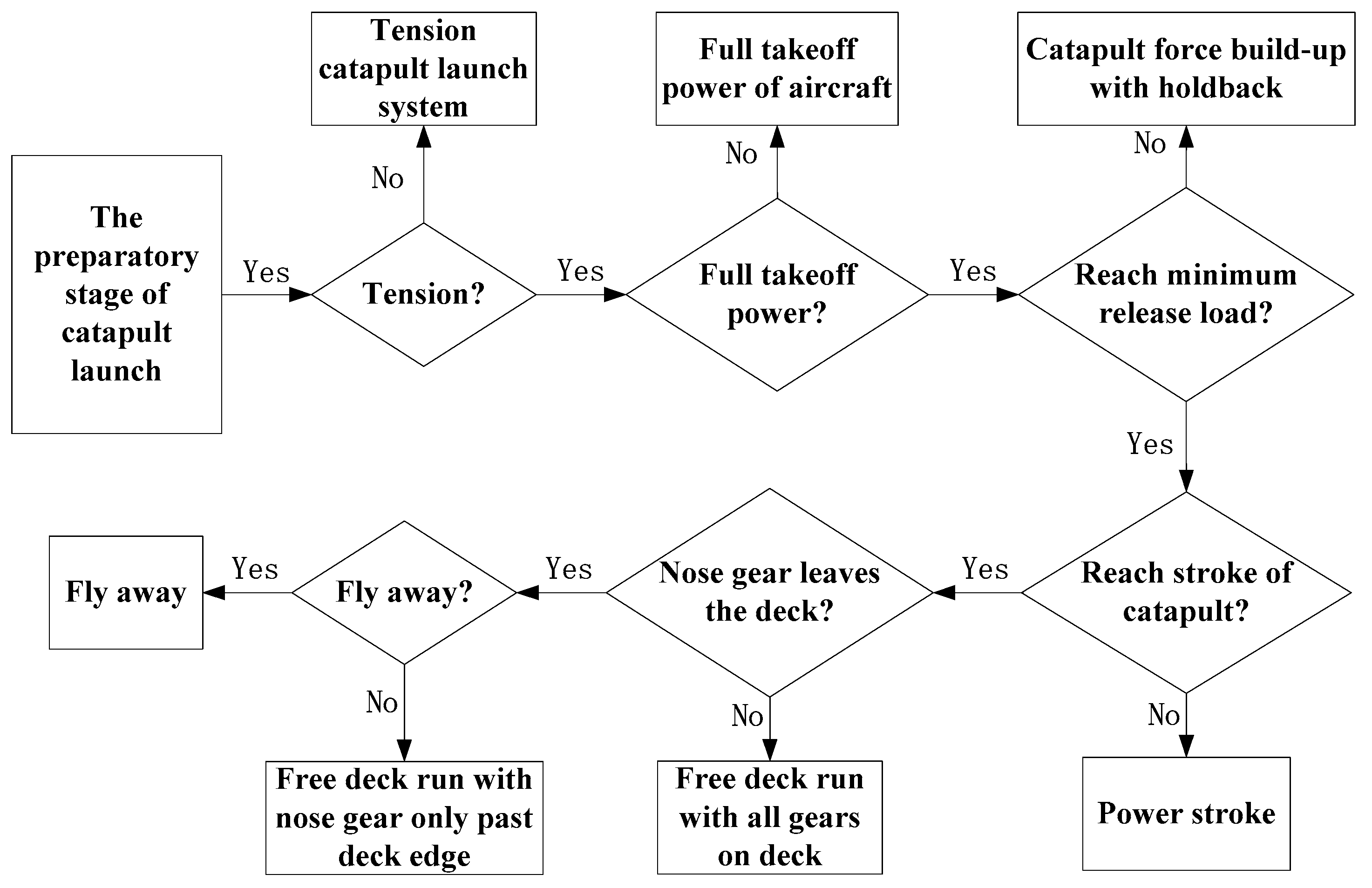
The flow chart of process for steam catapult launch is shown in Figure 2.
3. Mathematical Model of Wet Steam Accumulator Parameter Optimization
Catapult launch process for carrier-based aircraft is mainly divided into nine stages in Section 2. In this article, the mathematical model of catapult launch process is corresponding to the latter eight stages. The structure block diagram of catapult launch process for carrier-based aircraft is shown in Figure 3.
3.1. Modeling Assumptions.
- (1)
- The thermodynamic process of steam-powered catapult is an adiabatic process; this means that there is no heat transferred between steam catapult and the outside world.
- (2)
- Neglecting the space derivative for the state parameters of the steam-powered catapult, such as specific volume, temperature and enthalpy of the water and steam.
- (3)
- The wet steam accumulator and cylinder are rigid body.
- (4)
- The shape of wet steam accumulator is a circular cylinder.
- (5)
- The thermodynamic process of cylinder is a quasi-static process.
- (6)
- The steam has no friction with pipe wall during catapult launch for carrier-based aircraft.
- (7)
- The piston in cylinder is rigid body.
- (8)
- The fuselage of carrier-based aircraft is rigid body.
- (9)
- Neglecting the deck motion of aircraft carrier and airflow interference.
- (10)
- Carrier-based aircraft has no off-center during catapult launch.
- (11)
- The elevator angle is fixed during the whole process of catapult launch.
- (12)
- The mass of fuselage, wing and outer cylinder of shock absorber are regarded at nose gear rotation shaft, and use them as elastic support mass [22]; the mass of shock strut, wheel and tire are regarded at wheel axle, and use them as inelastic support mass.
3.2. Objective Function and Fitness Function of Wet Steam Accumulator Parameter Optimization
To guarantee the launching safety of carrier-based aircraft, there are three safety criterions which form the lower boundary of aircraft safety leaving from carrier [6].
- Maximal sink-off-the-bow (SOB). Maximal SOB is 10 feet sink-off-of-the-bow (downward vertical displacement of the center of gravity of the aircraft below the static plane of the carrier flight deck after flyaway). It should not exceed the maximum SOB during a safe launching aircraft.
- Maximum angle of attack. The maximum angle of attack permitted in the catapult maneuver is governed by the onset of buffet and the loss of lateral control. It cannot exceed the angle of attack for 0.9 with cockpit control position fixed.
- Minimum rate of climb. The aircraft must achieve and maintain a rate of climb of at least 600 feet per minute within three seconds after the time of maximum sink.
The purpose of optimizing wet steam accumulator parameters is to improve the safe launching of carrier-based aircraft. Define the objective function as:
where are the objective function, are the wet steam accumulator parameters required to be optimized, , are the lower and upper limits of the wet steam accumulator parameter, and , are the lower and upper limits of the objective function.
The pilots interviewed indicated that they greatly preferred no-sink launches and would not approve of any plans to alter this policy [6]. Therefore, the SOB is used to evaluate the launching quality, and the objective functions in Equation (1) are defined as:
In the following, the accumulator pressure, water level, accumulator volume and accumulator radius are defined as the accumulator parameters required to be optimized, and Equation (1) becomes:
where , are the objective function of angle of attack and the objective function of rate of climb, respectively.
The fitness function is used for evaluating the level of aptitude of every individual population relative to all others. It represents how likely an individual will survive, in other words, the more fitness, the most appropriate answer is. Selecting the fitness function plays an important role in convergence to the desired solution.
The fitness function of wet steam accumulator parameter optimization can be expressed as:
3.3. Genetic Algorithm
Genetic algorithms (GA) is a metaheuristic inspired by the process of natural selection. They are commonly used to generate high-quality solutions to optimization by relying on bio-inspired operators such as selection, crossover and mutation. The flow chart of the GA-algorithm is shown in Figure 4.
3.3.1. Initialization Operation
In the first stage of the GA, the initial population is generated randomly to commence the search space. The individuals of the population are coded as chromosomes with bit strings.
3.3.2. Selection Operation
During this stage, a part of the existing population is selected to breed the next generation. The easiest way of selection operation is to use a roulette wheel. The selection method of roulette wheel preferentially selects the best solution. In roulette wheel selection, the fitness function generates a fitness to solutions. This fitness level represents a probability of selection with each chromosome. In this article, we use a roulette wheel for breeding the next generation.
3.3.3. Crossover Operator and Mutation Operator
The next stage is to generate a second generation population from the above selection operation. The crossover is a genetic operator used for combining the genetic information of two parents to generate new offspring. It can generate new solutions from an existing population. After the crossover operator, mutation operator occurs according to a mutation probability. Mutation operator is used for maintaining genetic diversity from one generation to the next. In mutation, the solution may change completely from the previous solution.
3.4. Thermodynamics Model of Steam-Powered Catapult
Steam-powered catapult is mainly made up of steam accumulator, launch valve, cylinder, and piston, as shown in Figure 1. The following content are thermodynamics model of wet steam accumulator, mathematical model of launch valve and thermodynamics model of cylinder.
3.4.1. Thermodynamics Model of Wet Steam Accumulator
The latent heat of vaporization of water is calculated as [23]:
The evaporation rate is calculated as [5]:
The water mass change with evaporation and condensation rates is calculated as [5]:
The charging control valve is closed when the launch valve is opened. The pressure of the wet steam accumulator is reducing during the discharging process of the wet steam accumulator. The water is superheated due to the decrease of pressure in wet steam accumulator. The condensation rate is equal to zero, and Equation (7) changes into:
The steam mass change due to evaporation and condensation rates is calculated as:
The conservation of water mass and steam mass can be described by:
The energy of outlet flows at the wet steam accumulator can be calculated as:
In this paper, the charging and discharging of water are not taken into account, and neither is the process of charging steam. Therefore, the net energy of water of inlet and outlet flows at the wet steam accumulator boundaries is calculated as , and the heat transfer rate from the superheated steam to the water is calculated as . The first-order differential equation for wet steam accumulator pressure is written as [5]:
The partial derivatives of thermodynamic properties of water and steam based on the basic equations for 1 and 2 can be calculated as [24]:
Due to and , the derivatives of specific enthalpies of the water and steam can be calculated as [5]:
The volume of water can be calculated as:
The Equation (15) can be expanded as follows:
, , we can write:
We only need plot the curve of vector versus vector because the two functions in Equation (17) have the same form. The plot is shown in Figure 5.
We can use the polyfit function of MATLAB to find the coefficients of a polynomial p(y1) of degree n that fits the data, p(y1(i)) to x1(i). The degree of polynomial is 6, Then, the relation of y1 and x1 in Equation (17) changes into:
Taking into account Equation (18), Equation (16) becomes:
where is the volume of steam in wet steam accumulator, and the water level of wet steam accumulator can be calculated by Equation (19).
In this paper, the others thermodynamic properties of water and steam can be calculated by IAPWS Industrial Formulation 1997 [25].
3.4.2. Mathematical Model of Launch Valve
Launch valve is a very important gear of catapult launch system which can get different catapult energies by adjusting the stroke of launch valve and effective launch valve opening area. In order to make the model of launch valve conform to real condition mostly, this article used the test data of the stroke of launch valve and effective launch valve opening area [26]. The test data of the launch valve are shown in Figure 6.
The mass flow rate can be calculated as [11]:
The critical pressure equation can be calculated as [11]:
The equivalent effective cross-sectional area of launch valve and pipe’s equation comes from [11], and the pipe is between wet steam accumulator and cylinder:
3.4.3. Thermodynamics Model of Cylinder
We can get the differential equation of steam pressure inside the cylinder from the article [11]:
The equation of steam pressure of piston:
3.5. Traction Release Device Methematical Model
3.5.1. Mathematical Model of Launch Bar
The launch bar can be mathematically modeled as [11]:
3.5.2. Mathematical Model of Holdback Bar
The holdback bar can be mathematically modeled as [11]:
3.6. Statics Model of Tensioning
3.6.1. Statics Model of Piston
The piston in cylinder is in a state of static equilibrium at tensioning. The statics model of piston can be calculated as [11]:
3.6.2. Statics Model of Aircraft
The aircraft is in a state of static equilibrium at tensioning. The statics model of aircraft can be calculated as [11]:
3.6.3. Statics Model of the Nose Gear
The vertical statics equations of elastic support mass and non-elastic support mass can be calculated as [11]:
3.7. Statics Model of Full Takeoff Power
This stage just changed the statics model of the aircraft relative to tensioning stage, and the statics model of aircraft can be calculated as [11]:
3.8. Mathematical Model of Catapult Force Build-Up with Holdback
3.8.1. Statics Model of Piston
The piston is in a state of static equilibrium during catapult force build-up with holdback. The piston in catapult force build-up with holdback process can be mathematically modeled as [11]:
3.8.2. Statics Model of Aircraft
The aircraft is in a state of static equilibrium at tensioning. The statics model of aircraft can be calculated as [11]:
3.8.3. Dynamics Model of Nose Gear
The vertical dynamics equations of elastic support mass and non-elastic support mass can be calculated as [11]:
3.9. Mathematical Model of Release
The holdback bar is broken when the axial load of holdback bar reaches the minimum release load during catapult force build-up with holdback. The release stage is a point in the launching operation at which the aircraft is effectively released. The minimum release load can be calculated as [27]:
3.10. Dynamics Model of Power Stroke
3.10.1. Dynamics Model of Piston
3.10.2. Dynamics Model of Aircraft
3.10.3. Dynamics Model of Nose Gear
The vertical dynamics equations of elastic support mass and non-elastic support mass can be calculated as [11]:
3.11. Dynamics Model of Free Deck Run
The dynamics model of free deck run contains the model of free deck run with all gears on deck and the model free deck run with nose gear only past deck edge.
3.11.1. Dynamics Model of Aircraft
The dynamics equation of longitudinal aircraft is:
3.11.2. Dynamics Model of Nose Gear
The vertical dynamics equations of elastic support mass and non-elastic support mass can be calculated as:
3.12. Dynamics Model of Fly Away
The longitudinal dynamics equation of aircraft is:
The vertical dynamics equation of aircraft is:
The aerodynamic moment about center of gravity can be calculated as [6]:
The total moment about center of gravity can be calculated as [6]:
Using the moment of momentum theorem, the angular acceleration of the aircraft can be calculated as:
4. Experiment Design and Verification of the Parameters Optimization
We can get the simulation system of catapult launch process by building mathematical model of every stage in turn. The results of the static balance were used as the initial conditions in the equations of motion. The simulation curve started at the beginning of catapult force build-up with holdback stage in this paper. Every current stage prepared the initial condition for the latter stage.
4.1. Experiment Design and Results of Multiple Parameters Optimization
The pressure of wet steam accumulator , volume of wet steam accumulator , wet steam accumulator radius and water level are considered as the optimization parameters. GA parameters used for wet steam accumulator optimization are shown in Table 1.
The SOB versus the corresponding iteration number is shown in Figure 7. As mentioned earlier, the better launching performance we have, the smaller SOB we have. Therefore, the optimal wet steam accumulator parameters for objective function appear on 100 generation in Figure 7. The optimal wet steam accumulator parameters is MPa, m3, m, m.
4.2. Simulation Verification and Analysis of the Optimal Wet Steam Accumulator Parameters
In order to verify the effect of the optimal parameters, the comparison between optimal parameters and contrast parameters ( MPa, m3, m, m) are shown in Figure 8, Figure 9 and Figure 10.
Figure 8 displays the height of the center of gravity for aircraft. The height of the center of gravity for aircraft can obtain SOB (downward vertical displacement of the center of gravity of the aircraft below the static plane of the carrier flight deck after flyaway). The SOB, angle of attack and rate of climb are used to create the objective function. The multi-objective optimization can be converted to single-objective optimization, which is subject to angle of attack and rate of climb. In Figure 8, the SOB of optimal parameters and contrast parameters are 0.062 m and 1.12 m respectively, which are both less than 3.05 m. The better launching performance we have, the smaller SOB we have. Therefore, the optimal parameters have the better optimization for wet steam accumulator of steam-powered catapult.
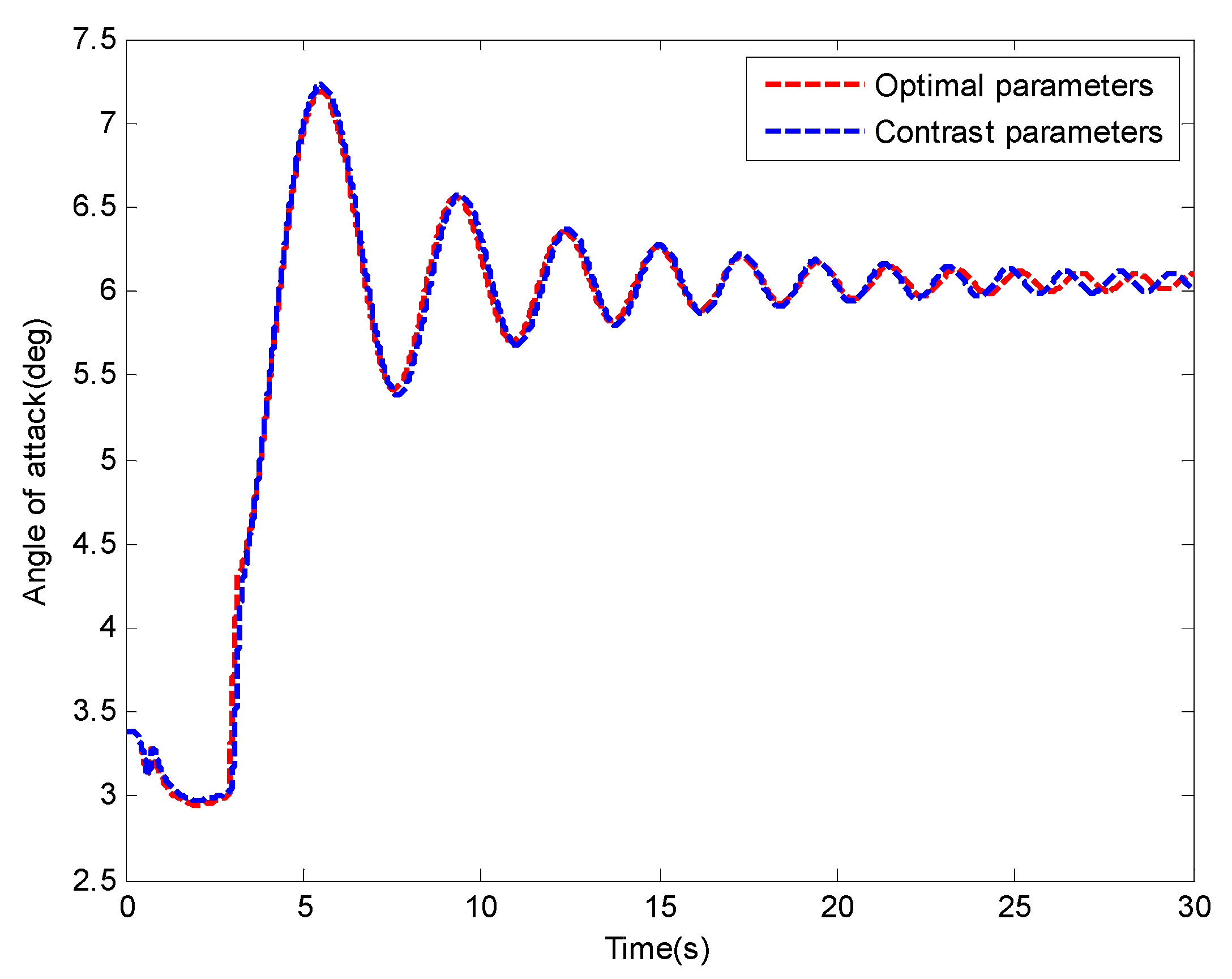
The obtained AOAs of aircraft are shown in Figure 9. There is no automatic flight control system (AFCS) in the steam-powered catapult launch simulation system in this paper. The flying qualities of aircraft only depended on aerodynamic design. Since the AFCS system is not applied, the angle of attack is going to fluctuation after flyaway. In the climbing process, all of the maximal attack angles are smaller than the allowable safe value (15 deg), and the AOAs stabilize into a small attack angle at a high speed [18]. In Figure 9, the AOAs of optimal parameters and contrast parameters are 7.188 deg and 7.224 deg, respectively, which are both less than the allowable maximal AOA after the aircraft fly away. All angles of attack are within the safe range.
Figure 10 shows the rate of climb of aircraft. The time of the aircrafts with optimal parameters and contrast parameters reach in SOB are 4.11 s and 5.90 s, respectively. In the three safe criterions, the aircraft must achieve and maintain a rate of climb of at least 600 feet per minute (3.05 m/s) within three seconds after the point of maximum sink [6]. The aircraft with optimal parameters achieve a rate of climb of 3.831 m/s within three seconds after the time of maximum sink. The aircraft with contrast parameters achieve a rate of climb of −0.072 m/s within three seconds after the time of maximum sink. Therefore, the aircraft with optimal parameters can safely launch from carrier. On the contrary, the aircraft with contrast parameters cannot be launched safely.
It is verified that the proposed multi-parameter optimization method is effective, and that the method can find the optimal parameters of wet steam accumulator of steam-powered catapult, which can increase the safe launching of aircraft during catapult launch process.
5. Conclusions
This paper addresses the problem of parameters optimization for wet steam accumulator of steam-powered catapult. The sink off bow (SOB), the angle of attack (AOA), and the rate of climb are used to construct an objective function which includes four wet steam accumulator parameters: accumulator pressure, water level, accumulator volume and accumulator radius. The multi-objective optimization can be converted to single-objective optimization, which is subject to angle of attack, rate of climb and the SOB as an objective function. By minimizing the SOB, it can obtain the optimal parameters of wet steam accumulator. In this paper, several points have been summarized as follows:
- (1)
- A completely mathematical model of catapult launch of the aircraft used to parameters optimization for wet steam accumulator is established. This complete mathematical model is composed of thermodynamics model of steam-powered catapult, mathematical model of traction release device, statics model of tensioning, statics model of full takeoff power, mathematical model of catapult force build-up with holdback, model of release, dynamics model of power stroke, dynamics model of free deck run and dynamics model of fly away.
- (2)
- An effective GA method used for parameter optimization of wet steam accumulator of steam-powered catapult has been presented, and it can find the optimal parameters of wet steam accumulator to increase the safe launching of aircraft during catapult launch process.
- (3)
- The study result can give a theory reference to design and test the wet steam accumulator for steam-powered catapult.
Author Contributions
Software: P.L.; writing—original draft: Q.Z. and P.L.; writing—review and editing: Q.Z., P.L., Z.Y., X.J., and Y.H.
Funding
This research was funded by International Science & Technology Cooperation Program of China (2013DFR10030). This research was funded by National Natural Science Foundation of China (61603110, 61803116, U1530119). This research was funded by fundamental research funds for the central universities (HEUCFM170401).
Conflicts of Interest
The authors declare no conflict of interest.
Nomenclature
| Steam pressure of wet steam accumulator, MPa | |
| Water level of wet steam accumulator, m | |
| Volume of wet steam accumulator, m3 | |
| Radius of wet steam accumulator, m | |
| The latent heat of vaporization of water, kJ/kg | |
| Specific enthalpy of the saturated steam in wet steam accumulator, kJ/kg | |
| Specific enthalpy of the saturated water, kJ/kg | |
| Evaporation rate of water, kg/s | |
| Density of water, kg/m3 | |
| Volume of water, m3 | |
| Specific enthalpy of water, kJ/kg | |
| Relaxation time, s | |
| The water mass changes due to evaporation and condensation rates, kg/s | |
| The steam mass changes due to evaporation and condensation rates, kg/s | |
| Condensation rate of water, kg/s | |
| Mass flow rate at steam outlet, kg/s | |
| The energy of outlet flows at the wet steam accumulator, kJ/s | |
| Specific enthalpy of steam in wet steam accumulator, kJ/kg | |
| Partial derivatives of thermodynamic properties of water and steam, m3/kJ | |
| Partial derivatives of thermodynamic properties of water and steam, m3/kg·MPa | |
| Specific volume of water, m3/kg | |
| Specific volume of steam in wet steam accumulator, m3/kg | |
| Net energy of water where inlet and outlet flows at the wet steam accumulator boundaries, kJ/s | |
| Heat transfer rate from the superheated steam to the water, kJ/s | |
| Mass of water, kg | |
| Mass of steam in wet steam accumulator, kg | |
| Isobaric cubic expansion coefficient of water, K−1 | |
| Isobaric cubic expansion coefficient of steam, K−1 | |
| Specific isobaric heat capacity of water, kJ/kg·K | |
| Specific isobaric heat capacity of steam, kJ/kg·K | |
| Isothermal compressibility of water, MPa−1 | |
| Isothermal compressibility of steam, MPa−1 | |
| Thermodynamic temperature of water, K | |
| Thermodynamic temperature of steam in wet steam accumulator, K | |
| The length of wet steam accumulator, m | |
| Volume of steam in wet steam accumulator, m3 | |
| Equivalent effective cross-sectional area of launch valve and pipe between wet steam accumulator and cylinder, m2 | |
| Ratio of specific heat | |
| Gas constant of steam, J/kg·K | |
| Steam pressure of cylinder, MPa | |
| Critical pressure, MPa | |
| Accumulator outlet area, m2 | |
| Effective launch valve opening area, m2 | |
| Cylinder inlet area, m2 | |
| Displacement of piston, m | |
| Area of steam act on piston, m2 | |
| Initial displacement of piston, m | |
| Steam pressure of act on piston, N | |
| Steam pressure of act on piston on the other side, MPa | |
| Area of steam act on piston on the other side, m2 | |
| Catapult force of launch bar, N | |
| Axial load of launch bar, N | |
| Angle between launch bar axis and deck, Deg | |
| Vertical component of axial load of launch bar, N | |
| Longitudinal component of axial load of holdback bar, N | |
| Axial load of holdback bar, N | |
| Angle between holdback axis and deck, Deg | |
| Vertical component of axial load of holdback bar, N | |
| Tensioning force, N | |
| Friction force of piston, N | |
| Mass of piston, kg | |
| Acceleration due to gravity, m/s2 | |
| Coefficient of friction between the piston and cylinder wall | |
| Friction force between nose gear and deck, N | |
| Friction force between landing gear and deck, N | |
| Deck reaction of nose gear, N | |
| Coefficient of friction between deck and tire | |
| Deck reaction of landing gear, N | |
| Mass of aircraft, kg | |
| Elastic support mass, kg | |
| Air spring force, N | |
| Non-elastic support mass, kg | |
| Thrust of aircraft, N | |
| Pitch angle of aircraft, Deg | |
| Strut friction force of nose gear, N | |
| Hydraulic damping force of nose gear, N | |
| Acceleration of elastic support mass, m/s2 | |
| Gear stroking velocity, m/s | |
| Acceleration of non-elastic support mass, m/s2 | |
| Minimum release load of holdback bar, N | |
| Maximum design weight of aircraft, N | |
| Acceleration of piston, m/s2 | |
| Aerodynamic drag, N | |
| Acceleration of aircraft, m/s2 | |
| Equivalent aerodynamic lift act on nose gear, N | |
| Displacement of non-elastic support mass, m | |
| Radius of tire of nose gear, m | |
| Aerodynamic lift, N | |
| Flight path angle, Deg | |
| Longitudinal component of acceleration of aircraft, m/s2 | |
| Vertical component of acceleration of aircraft, m/s2 | |
| Aerodynamic moment about c.g., N·m | |
| Air density, kg/m3 | |
| Wing area of aircraft, m2 | |
| Speed of aircraft, m/s | |
| Mean geometric chord, m | |
| Aerodynamic pitching moment coefficient | |
| Body axis lift moment arm, m | |
| Aerodynamic lift at aircraft fixed axis system, N | |
| Body axis drag moment arm, m | |
| Aerodynamic drag at aircraft body-fixed coordinate system, N | |
| Total moment about c.g., N·m | |
| Thrust moment arm, m | |
| Pitch angular acceleration about the c.g., Deg/s2 | |
| Moment of inertia in pitch, kg·m2 | |
| At the time of maximal SOB, s | |
| Peak angle of attack, Deg | |
| Climb rate after the time of maximal SOB, m/s |
References
- Shevach, G.; Blair, M.R.; Hing, J.; Venetsky, L.; Martin, E.; Wheelock, J. Towards Performance Prognostics of a Launch Valve; Naval Air Warfare Center Lakehurst United States: Lakehurst, NJ, USA, 2014.
- Slavin, F.J. Aircraft steam catapult. Mech. Eng. 1969, 91, 42–46. [Google Scholar]
- Sun, B.Z.; Guo, J.M.; Lei, Y.; Yang, L.B.; Li, Y.J.; Zhang, G.L. Simulation and verification of a non-equilibrium thermodynamic model for a steam catapult’s steam accumulator. Int. J. Heat Mass Transf. 2015, 85, 88–97. [Google Scholar] [CrossRef]
- Steinmann, W.; Eck, M. Buffer storage for direct steam generation. Sol. Energy 2006, 80, 1277–1282. [Google Scholar] [CrossRef] [Green Version]
- Stevanovic, V.D.; Maslovaric, B.; Prica, S. Dynamics of steam accumulation. Appl. Therm. Eng. 2012, 37, 73–79. [Google Scholar] [CrossRef]
- Lucas, C.B. Catapult Criteria for A Carrier-Based Airplane; AD702814; Defense Technical Information Center: Fort Belvoir, WV, USA, 1968.
- Naval Air Engineering Center. Mil-Std-2066(AS) Military Standard Catapulting and Arresting Gear Forcing Functions for Aircraft Structural Design; Department of the Navy Air Systems Command: Patuxent, MD, USA, 1981.
- Cheng, G.; Ni, H.; Sun, F. Modeling and simulation research on naval steam-power aircraft launch system. J. Wuhan Univ. Technol. 2010, 34, 301–305. [Google Scholar]
- Zhu, Q.; Lu, P.; Yang, Z. Simulation research on deadload steam catapult systems. J. Harbin Eng. Univ. 2018, 39, 1979–1986. [Google Scholar]
- Shi, Y.; Shi, T.; Ma, W.; Gao, C. Design and simulation of inner and outer cylinder-type steam catapult. Adv. Mech. Eng. 2018, 10, 1–7. [Google Scholar] [CrossRef]
- Zhu, Q.; Lu, P.; Yang, Z.; Cui, Y. Model research of steam catapult launch process for carrier-based aircraft. In Proceedings of the 37th Chinese Control Conference, Wuhan, China, 25–27 July 2018. [Google Scholar]
- Yu, H.; Nie, H. Dynamics analysis of carrier-based aircraft with off-center catapult launch. J. Nanjing Univ. Aeronaut. Astronaut. 2010, 42, 537–542. [Google Scholar]
- Zhu, Q.; Liu, H.; Li, X. Research on carrier-based aircraft catapult launching in the case of different eccentricity. Flight Dyn. 2016, 34, 10–14. [Google Scholar]
- Wei, X.; Liu, C.; Nie, H.; Zhang, M.; Yin, Q. Dynamics and test method of carrier-based aircraft nose landing gear sudden extension. Acta Aeronaut. Astronaut. Sin. 2013, 34, 1363–1369. [Google Scholar]
- Zhang, M.; Nie, H.; He, Z. Parameter optimization of nose landing gear considering both take-off and landing performance of catapult take-off carrier-based aircraft. Trans. Nanjing Univ. Astronaut. Aeronaut. 2016, 33, 187–198. [Google Scholar]
- Eppel, J.C.; Hardy, G.; Martin, J.L. Flight Investigation of the Use of A Nose Gear Jump Strut to Reduce Takeoff Ground Roll Distance of Stol Aircraft; Ames Research Center, National Aeronautics and Space Administration: Moffett Field, CA, USA, 1994.
- Wilson, T. F-35 carrier suitability testing. In Proceedings of the 2018 Aviation Technology, Integration, and Operations Conference, Atlanta, GA, USA, 25–29 June 2018. [Google Scholar]
- Zhen, Z.; Jiang, J.; Wang, X.; Li, K. Modeling, control design, and influence analysis of catapult-assisted take-off process for carrier-based aircrafts. Proc. Inst. Mech. Eng. Part G J. Aerosp. Eng. 2018, 232, 2527–2540. [Google Scholar] [CrossRef]
- Loftus, J.; Piekarski, B. Carrier suitability tests of the rafale airplane in the united states. In Proceedings of the Biennial Flight Test Conference, Hilton Head, SC, USA, 20–23 June 1994. [Google Scholar]
- Wallace, M.M. F/A-18E/F Catapult Minimum End Airspeed Testing. Master’s Thesis, University of Tennessee, Knoxville, TN, USA, 2002. [Google Scholar]
- Naval Air Engineering Center. Mil-L-22589d(AS) Launching System, Nose Gear Type, Aircraft; Naval Air Engineering Center: Lakehurst, NJ, USA, 1991.
- Zhu, Q.; Li, X.; Yu, Y. Analysis of dynamic characteristics of catapult launch for a carrier-based aircraft with sudden load discharge. J. Harbin Eng. Univ. 2012, 33, 1150–1157. [Google Scholar]
- Sanford, K.; Gregory, N. Thermodynamics; Cambridge University Press: New York, NY, USA, 2012. [Google Scholar]
- Wagner, W.; Kretzschmar, H.J. International Steam Tables; Springer: Berlin, Germany, 2007. [Google Scholar]
- Wagner, W.; Cooper, J.R.; Dittmann, A.; Kijima, J.; Kretzschmar, H.-J.; Kruse, A.; Mares, R.; Oguchi, K.; Sato, H.; Stocker, I.; et al. The IAPWS Industrial Formulation 1997 for the Thermodynamic Properties of Water and Steam. ASME J. Eng. Gas Turbines Power 2000, 122, 150–182. [Google Scholar] [CrossRef]
- U.S. Naval Air Engineering Center. Evaluation of Advanced Method for Steam Catapult Performance Prediction with Shipboard Test Data; AD742804; U.S. Naval Air Engineering Center: Lakehurst, NJ, USA, 1972.
- MIL-A-8863C. Airplane Strength and Rigidity Ground Loads for Navy Acquired Airplanes; United States Coast Guard: Washington, DC, USA, 1993. [Google Scholar]
Figure 1.
The general steam-powered catapult launch system for carrier-based aircraft.
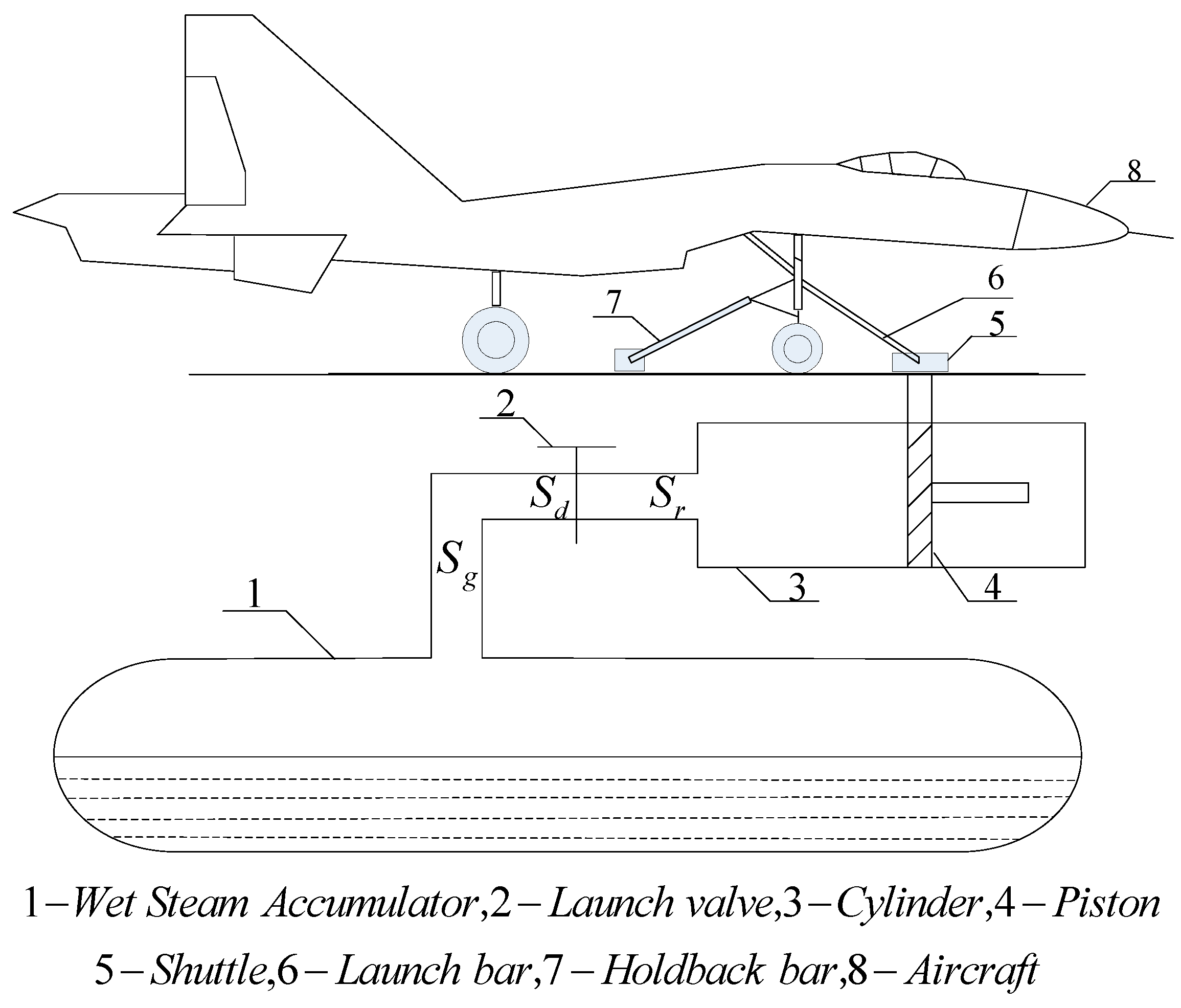
Figure 2.
The flow chart of process for steam catapult launch.

Figure 3.
Structure block diagram of steam catapult launch process.

Figure 4.
The flow chart of genetic algorithm.
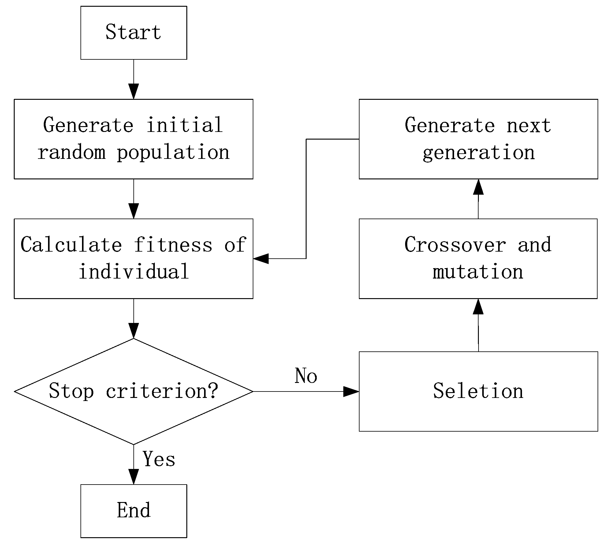
Figure 5.
The curve of x1-coordinate mapping to y1-coordinate.
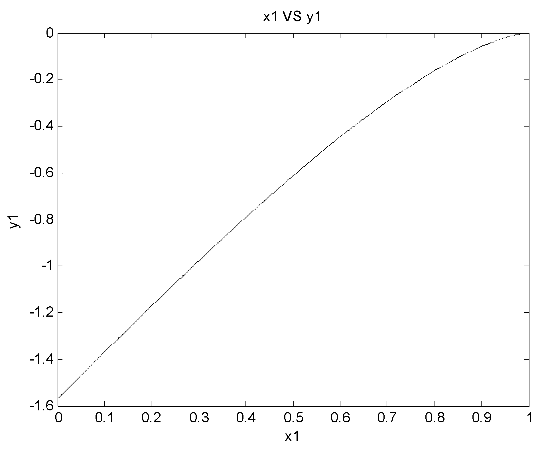
Figure 6.
The test data of the stroke of launch valve and effective launch valve opening area: (a) Launch valve stroke; (b) Effective launch valve opening area.
Figure 6.
The test data of the stroke of launch valve and effective launch valve opening area: (a) Launch valve stroke; (b) Effective launch valve opening area.
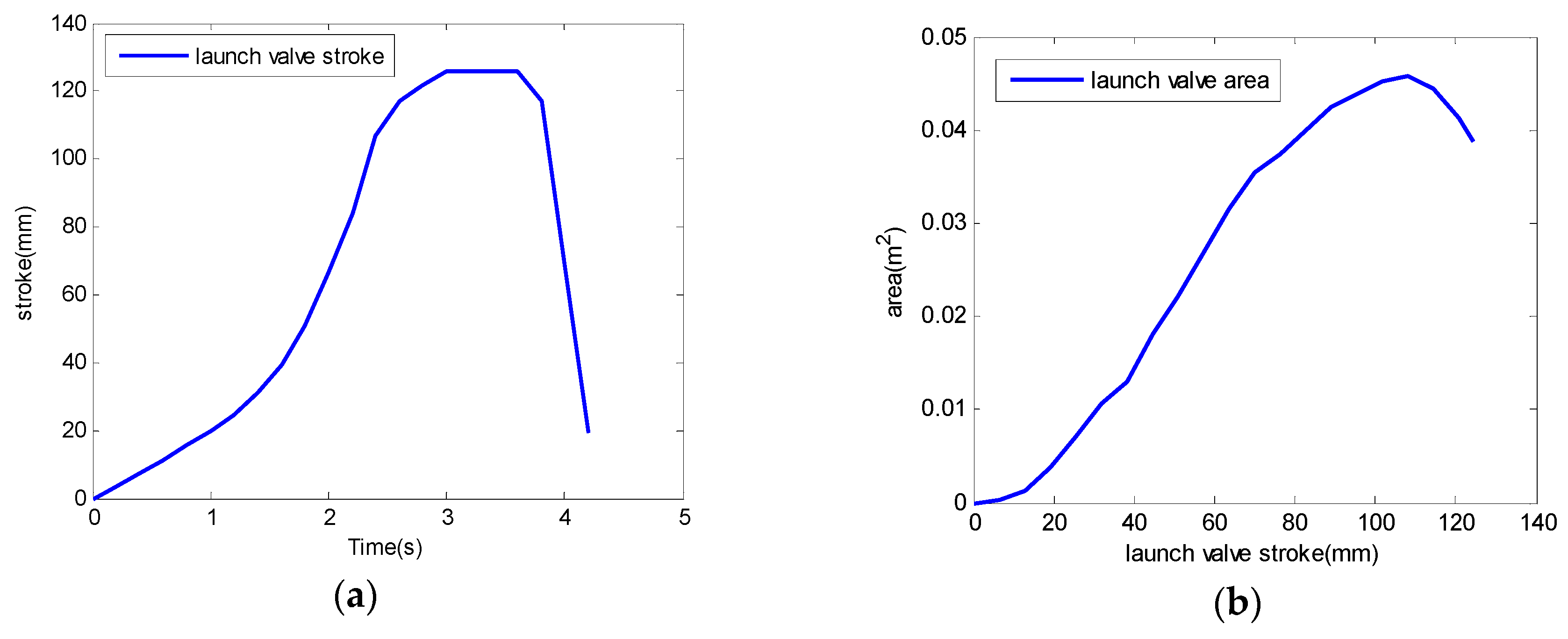
Figure 7.
Optimized SOB using a genetic algorithm versus iteration number.
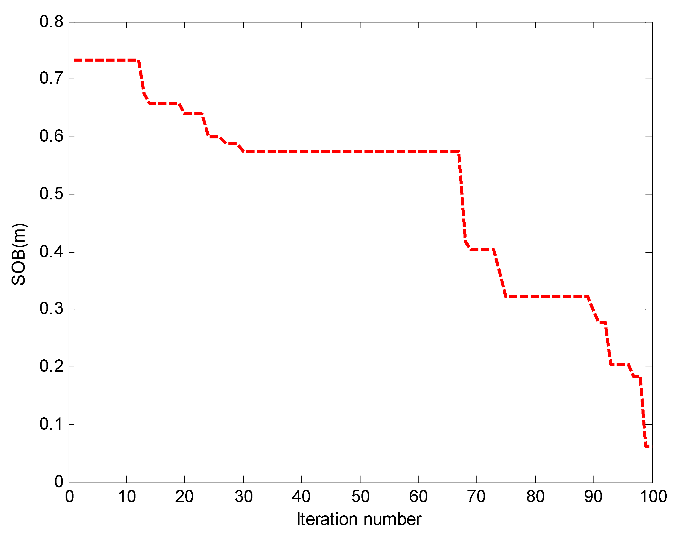
Figure 8.
Center of gravity location of aircraft.

Figure 9.
Angle of attack of aircraft.

Figure 10.
Climb rate of aircraft.


Table 1.
GA parameters used for wet steam accumulator optimization.
| GA Parameter | Selection |
|---|---|
| Population size | 50 |
| Design variables | 4 |
| Probability of crossover | 0.8 |
| Probability of mutation | 0.01 |
| Selection operator | Roulette-wheel |
| Crossover operator | Single point |
| Mutation operator | Bit-wise |
© 2019 by the authors. Licensee MDPI, Basel, Switzerland. This article is an open access article distributed under the terms and conditions of the Creative Commons Attribution (CC BY) license (http://creativecommons.org/licenses/by/4.0/).
Share and Cite
MDPI and ACS Style
Zhu, Q.; Lu, P.; Yang, Z.; Ji, X.; Han, Y. Multi-Parameter Optimization for the Wet Steam Accumulator of a Steam-Powered Catapult. Energies 2019, 12, 234. https://doi.org/10.3390/en12020234
AMA Style
Zhu Q, Lu P, Yang Z, Ji X, Han Y. Multi-Parameter Optimization for the Wet Steam Accumulator of a Steam-Powered Catapult. Energies. 2019; 12(2):234. https://doi.org/10.3390/en12020234
Chicago/Turabian StyleZhu, Qidan, Peng Lu, Zhibo Yang, Xun Ji, and Yu Han. 2019. "Multi-Parameter Optimization for the Wet Steam Accumulator of a Steam-Powered Catapult" Energies 12, no. 2: 234. https://doi.org/10.3390/en12020234
Note that from the first issue of 2016, this journal uses article numbers instead of page numbers. See further details here.