Study of a Piezoelectric Energy Harvesting Floor Structure with Force Amplification Mechanism


Department of Instrumental and Electrical Engineering, Xiamen University, Xiamen 361005, China
*
Author to whom correspondence should be addressed.
Energies 2019, 12(18), 3516; https://doi.org/10.3390/en12183516
Submission received: 13 August 2019
/
Revised: 2 September 2019
/
Accepted: 10 September 2019
/
Published: 12 September 2019
(This article belongs to the Section A: Sustainable Energy)
Abstract
:This paper proposes a novel energy harvesting floor structure using piezoelectric elements for converting energy from human steps into electricity. The piezoelectric energy harvesting structure was constructed by a force amplification mechanism and a double-layer squeezing structure in which piezoelectric beams were deployed. The generated electrical voltage and output power were investigated in practical conditions under different strokes and step frequencies. The maximum peak-to-peak voltage was found to be 51.2 V at a stroke of 5 mm and a step frequency of 1.81 Hz. In addition, the corresponding output power for a single piezoelectric beam was tested to be 134.2 μW, demonstrating the potential of harvesting energy from the pedestrians for powering low-power electronic devices.
1. Introduction
In recent years, with the development of intelligent devices and wireless sensor networks, supplying power to low-power electronic devices has attracted increasing interest [1,2,3]. However, there are several issues regarding traditional battery-powered methods such as limited lifespan and energy storage capacity, etc. Alternatively, kinetic energy is ubiquitous in our daily activities, thus harvesting kinetic energy from the ambient environment to provide sustainable power to these devices is highly desirable. Many kinetic energy harvesters have been developed using different conversion methods, including electromagnetic [4], triboelectric [5], electrostatic [6], and piezoelectric [7] conversions. Among these methods, piezoelectric convertors have attracted much attention due to the fact of their simple structure and high efficiency in energy conversion [8]. In this study, our purpose was to design an energy harvesting floor structure to harvest the energy from foot strikes. As footsteps are usually at low frequency and only small stroke are allowed [9], an efficient converting structure was needed.
At present, many piezoelectric energy harvesters are resonance-based devices, which matches the resonant frequency of the structure and the frequency of the vibration source in order to achieve high efficiency. However, footstep frequency is low and varies. Once the striking frequency deviates from the resonant frequency of the harvester, the output power will decrease significantly [10,11]. Therefore, non-resonance structures are usually considered in energy harvesting floor structures.
Kim et al. [12] designed a piezoelectric energy harvesting floor with a novel piezoelectric material, which was capable of powering a wireless sensor node. The results showed that when a person stepped on the floor tile, the peak output voltage and current of 42 V and 11 μA was generated. The focus of their work was the fabrication of the high-performance piezoelectric material. However, the structure of the energy harvester was not optimally designed and could be further improved. Puscasu et al. [13] fabricated a bistable piezoelectric energy harvesting floor structure and placed it under a stair nosing which powered embedded emergency lighting. The resultant energy density was 0.49 J per meter square and per step. Panthongsy et al. [14] utilized a piezoelectric frequency up-converting mechanism in the design of energy harvesting floor. The results showed that the average power and total output energy produced by one footstep on the tile were 1.24 mW and 3.49 mJ, respectively. But the above two structures both have the same problem; the piezoelectric elements in their structures are not evenly stressed under the stepping force. The piezoelectric elements away from the foot when the structure is pressed will suffer smaller stresses than the elements directly under the foot.
Considering that the applied force on the floor is perpendicular to the floor surface, a force amplification mechanism can be used to convert the vertical force into a horizontal force, thus enlarging the force. Force amplification mechanisms have been used in some piezoelectric energy harvesters. Kuang et al. [15] designed a sandwiched piezoelectric energy harvester with a force amplification mechanism to amplify the load and a substrate structure to increase the load capacity. Wen et al. [16] proposed a piezoelectric energy harvester consisting of a compound two-stage force amplification frame to generate highly efficient electricity for a piezoelectric stack.
This paper proposed a novel energy harvesting floor structure utilizing a force amplification mechanism, a double-layer squeezing structure, and piezoelectric clamped–clamped beams. The piezoelectric elements mounted on the clamped–clamped beams would deflect under the combined tensile stress and bending stress. The whole mechanism was designed to provide enough stress to each piezoelectric element and to guarantee that the deflections of the piezoelectric elements are within a safe limit. Another virtue of the mechanism is that the piezoelectric beams in our designed structure can be subjected to evenly distributed stressors from a stepping force.
2. Design of the Energy Harvesting Floor Structure
2.1. The Force Amplification Mechanism
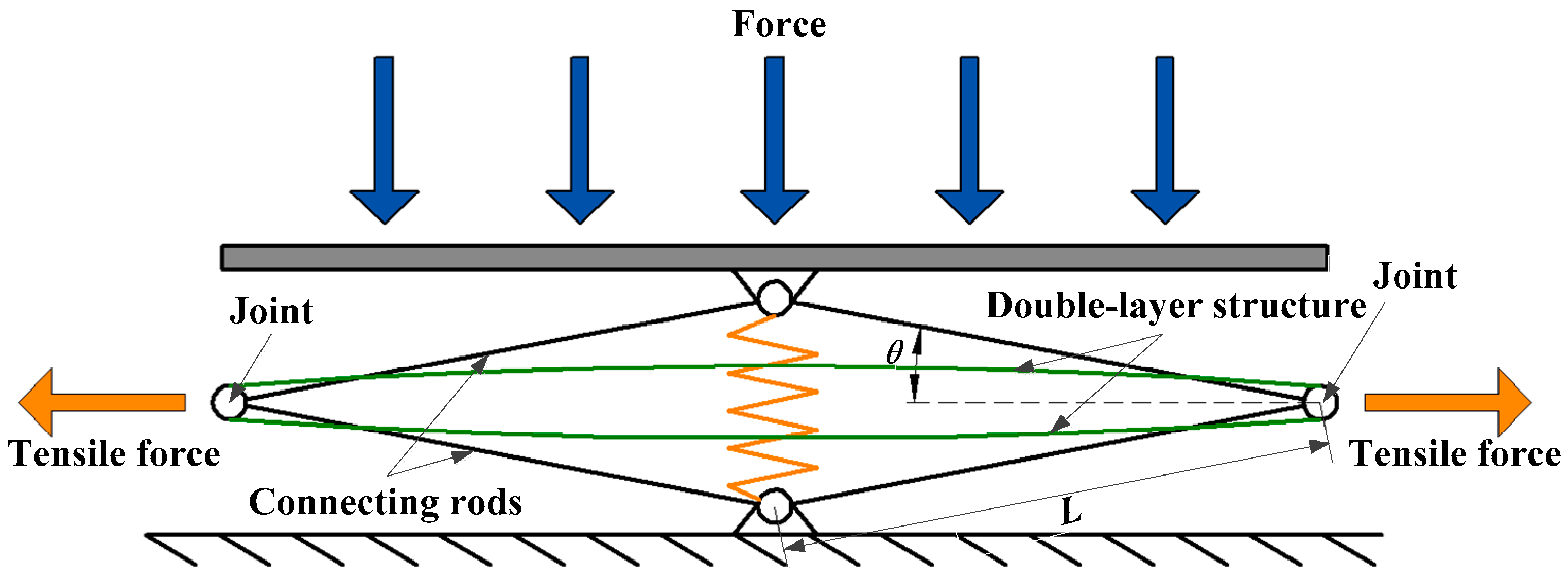
The energy harvesting floor structure is built using a force amplification mechanism based on linkage mechanism theory. The schematic diagram of the force amplification mechanism is illustrated in Figure 1. The force amplification mechanism contained 8 connecting rods which were linked together with joints. The length of each connecting rod was denoted as L. The angles of the connecting rods with respect to the horizontal plane were the same and denoted as θ. The double-layer structure also connected two joints at the sides. On the top of the structure, a slab was used as the floor surface. Springs were installed vertically connecting the top joint and the bottom joint. It can absorb a part of the impact energy from the foot strike and provide an elastic force to make the slab board move upward while the foot moves away from the board.
The eight rods are made of aluminum alloy, which is a light metal with high strength, and the 4 joints were made of stainless steel with higher strength. When there is a foot strike, the vertical force can be converted into tensile force in the horizontal plane and the force is amplified. In addition, the amplified tensile force will stretch the double-layer structure. Under the compressed state, the elastic forces from the springs are much smaller than the vertical force from a pedestrian and can be neglected in calculating the tensile force. The tensile force T can be approximately calculated by T = (m∙g)/tanθ, where m represents the mass of the pedestrian and g represents the gravitational acceleration.
2.2. The Double-Layer Squeezing Structure and Piezoelectric Beams Array
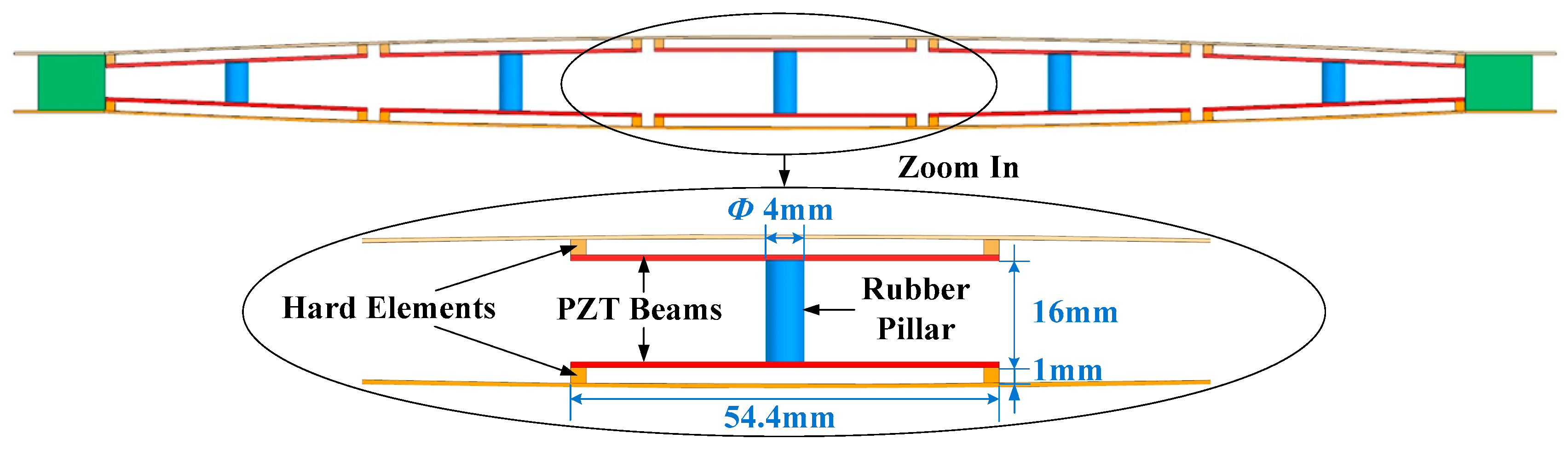
In a traditional force amplification mechanism, the piezoelectric element is surface bonded to a substrate and extracted under tensile force. However, a considerable amount of tensile force is absorbed by the substrate. The resultant tensile stressors on the piezoelectric elements are not large enough. In this paper, a double-layer squeezing structure was designed to replace the traditional one-layer substrate in the amplification mechanism. It consisted of two pre-curved, thin aluminum plates. These two plates were separated from each other with uneven distances along the horizontal axis, as shown in Figure 2a. Piezoelectric clamped–clamped beams were bonded to the downside surface of the upper plate and the upside surface of the lower plate, face-to-face. In each piezoelectric beam, there were two hard elements bonded with the plate and the beam substrate. Two face-to-face piezoelectric beams become one beam. In every couple of piezoelectric beams, a rubber pillar was bonded to the centers of two piezoelectric beam substrates to make the beams deform during foot strikes. To guarantee the piezoelectric elements worked under the strength limit, stoppers were applied to restrict the vertical motion amplitude of the slab board.
In our design, the upper plate and the lower plate were made of aluminum alloy. The height of the hard elements in the clamped–clamped beam structure was 1 mm, which allowed the piezoelectric beams to deflect by 1 mm. Piezoelectric devices, model PPA-1001, were applied as the beam substrates. The PPA-1001 is packaged in protective polyamide layers, which significantly increases the robustness of the piezoelectric elements. A 4 × 5 array of piezoelectric beams can be mounted on both plates. The dimensions and properties of the two plates and the piezoelectric beam substrates are shown in Table 1. A couple of clamped–clamped piezoelectric beams in the center is shown at a closer view in Figure 3. Sixteen millimeter in height and 4 mm in diameter rubber pillars were bonded between every two beam substrates.
The deforming mechanism of the piezoelectric beams is illustrated in Figure 4. The unloaded states of the plates and beam were indicated by the dotted line. While the pedestrian steps on the slab board, the upper plate and the lower plate will be pulled tightly, and the distance between the two plates will decrease. The beams will bend as shown in Figure 4. The deforming mechanism is called “squeezing structure” in this paper. In this way, the piezoelectric beams will experience both the tensile stress resulting from the deformation of the plates as well as bending stress from the force of the rubber pillars. Another advantage of the proposed structure is that by elaborately setting the length of the rubber pillars, all the piezoelectric beams are subjected to enough large and evenly distributed stressors from a stepping force.
3. Experimental Validation
To verify the design of the proposed energy harvesting floor structure, a prototype was fabricated as shown in Figure 5. The length of each rod L was 150.75 mm, and the angle θ was set as 5.71° in the initial static state. The overall size of the structure was 300 × 250 × 70 mm3. During the test, a pedestrian of about 60 kg consecutively steps on and off the structure with different frequencies. To make it simple, only a group of piezoelectric beams in the center of the plate were tested to evaluate the performance of the prototype. The output voltages of the piezoelectric elements were measured with an oscilloscope (TDS1012SC, Tektronix, Shanghai, China).
3.1. Analysis of the Voltage Output Waveform
In the first experiment, the piezoelectric energy harvesting floor structure was tested at an excitation frequency of around 0.47 Hz. The downward stroke of the slab was restricted to 2 mm by the stoppers. The open-circuit voltage of the tested piezoelectric beam in the center of the lower plate was recorded as shown in Figure 6.
From Figure 6, each cycle of voltage waveform can be divided into four stages. Taking the time period of t1~t5 as an example, at moment t1, the pedestrian began to step on the floor and forced it to move downward. During the time interval (t1~t2), the slab was subjected an increasing force resulting from the pedestrian until the movement of the structure was restricted by the stoppers. It can be seen that the output voltage fell down rapidly. At time moment t2, the output voltage reached a negative peak value of −7.8 V. Then, the foot was lifted during the time interval (t2~t3). While the foot left the slab at time instant t3, the restoring forces of the springs kept the slab moving upward. During the time interval (t3~t4), the moving part of the structure showed a rapid speed, resulting in a rapid rising of the output voltage. At moment t4, the output voltage reached a positive peak value of 9.2 V. After that the voltage declined, until the energy generating cycle was completed at moment t5.
3.2. The Voltage Output Under Different Frequencies and Strokes
To investigate the harvested power with various slab strokes, experiments were conducted with different strokes from 2 mm to 5 mm with an increment of 1 mm. A comparison of the output voltage signals with different strokes is shown in Figure 7.
It can be seen that the peak-to-peak output voltages increased apparently by enlarging the stroke, and the maximum peak-to-peak voltage was 49 V at a stroke of 5 mm. It is easy to conclude that a significant increase in output power can be achieved by increasing the stroke. However, an excessively large stroke of the slab may cause an uncomfortable falling sense of the pedestrians. Therefore, a proper stroke should be set. In the following experiments, the stroke of the slab was set as 5 mm.
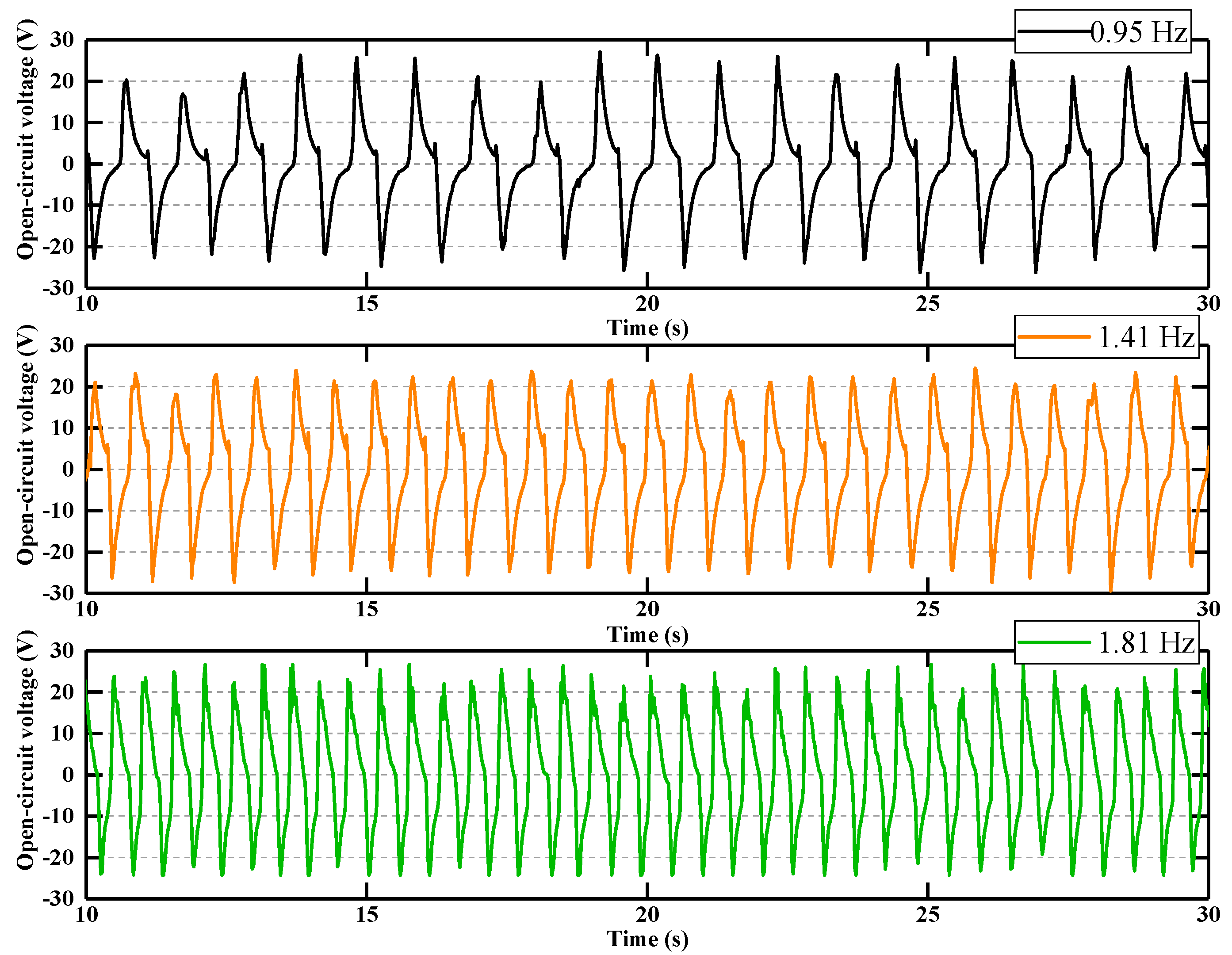
The output power is also related with step frequency. Experiments were conducted with step frequencies of 0.95 Hz, 1.41 Hz, and 1.81 Hz, respectively. The results are shown in Figure 8.
From the output voltages, the tested piezoelectric beam could output a peak-to-peak voltage of around 52.2 V with a step frequency of 0.95 Hz. When the step frequency increased to 1.81 Hz, the peak-to-peak voltage was around 51.4 V. From the tested results, it can be found that for different step frequencies, the peak-to-peak voltages were relatively stable. The reason may be that the stroke of the slab board was restricted. Nevertheless, the output power increased with the step frequency.
3.3. Optimal Resistive Load and Maximum Output Power
To obtain the maximum power from the harvester, the impedance of load should be optimized. Matching the impedance of piezoelectric elements using a resistive load is an efficient approach to extract the maximum power from piezoelectric materials. From the voltage waveform shown in Figure 6, it can be seen that the output voltage was not in a sinusoid form but an impact-induced response. The impact can convert the frequency of output voltage so that the matching impedance of the piezoelectric element is reduced dramatically, and a higher output power can be achieved [17].
The optimal matched resistive load for the impact-induced harvester is usually experimentally tested. In this paper, a computational method based on Fourier transform was used to find out the optimal resistive load and was then verified experimentally. Using an open-circuit voltage at 1.81 Hz step frequency and 5 mm stroke as an example, the voltage waveform in time domain was converted in frequency domain through Fourier transform and shown in Figure 9. The data above 25 Hz in the frequency domain were small and neglected. From Figure 9, it can be seen that there were four apparent peaks.
The voltage Vo(t) can be expressed as:
where f1~fn are the frequency points in the frequency domain; A1~An are the amplitudes of the voltages for each frequency point. ø1~øn are the phase angles for each frequency point. Theoretically, for each frequency point, the optimal resistive load Rn is:
where Cp is the capacitance of the piezoelectric element. In this prototype, the capacitance of the piezoelectric element in the tested beam was 99.7 nF. For each frequency point, the optimal resistive load was different. When the frequency increased, the optimal resistive load decreased. To find out the optimal resistive load for the output open-circuit voltage, it is difficult to solve the problem using equations. A computational method has to be applied. In the computational method, the load Rm was changed from 10 kΩ to 10 MΩ and 22 different load resistances were chosen for computation. For each load resistance, the following equation was used to find out the power output for one frequency component:
Then, all the power components from the frequency components for one particular load were added up to one power output Pm.
Based on the data in Figure 9 and Equations (2) and (3), the computational output power for different loads are shown as the plus-marked curve in Figure 10. The maximum computational power output was 131.1 μW. The optimal computational resistor was 550 kΩ.
Experiments were done to find out the optimal load resistance and maximum output power. In the experiments, different values of resistive load were connected with the piezoelectric element. The output voltages of the loads were used to find out the instant power and average power of each load. Through experiments, the experimental results are shown as the triangle-marked curve in Figure 10. It can be seen that the two curves matched well. The experimental optimal resistor was 500 kΩ and the experimental maximum power was 134.2 μW. Therefore, it was proved that using the computational method with data in frequency domain can predict the optimal resistive load and the maximum power output.
Through the computational method and experiments, the computational and experimental maximum output power of the tested piezoelectric beam at other frequencies and strokes were as follows. At 0.47 Hz excitation and 2 mm stroke, the maximum computational and experimental output power were only 2.63 μW and 2.72 μW, respectively. The maximum computational and experimental output power at 0.95 Hz excitation and 5 mm stroke were 46.58 μW and 48.18 μW, respectively. The maximum computational and experimental output power at 1.41 Hz excitation and 5 mm stroke were 88.45 μW and 91.18 μW, respectively.
It should be noted that the above output power is only for one piezoelectric beam. If 40 piezoelectric beams were applied, as the deflection limit of the beams were set the same as 1 mm, the output power for each piezoelectric beam can be considered as similar. The total power output of 40 beams inside one floor structure can reach 5.368 mW at 1.81 Hz excitation frequency and 5 mm stroke.
4. Conclusions and Discussions
In this research, a novel energy harvesting floor structure was designed and experimentally tested. An amplification mechanism was designed to enlarge the force from the pedestrian. A squeezing structure was designed to bend the clamped–clamped piezoelectric beams. A combined bending stress and tensile stress were exerted on the piezoelectric element during the strike. Through the structure, all the piezoelectric beams could be subjected to large enough and evenly distributed stressors from a stepping force.
The performances of the energy harvesting floor structure were evaluated with experiments. Evaluations were performed with different strokes and step frequencies. It can be seen from the experimental results that the peak-to-peak voltage of the piezoelectric element increased from 18.8 V to 51.4 V with the increasing stroke of the slab board. Through experiments with different step frequencies, it was found that with the increasing of the step frequency, the output power rather than the output voltage amplitude increased. A computational method based on Fourier transform was proposed to estimate the optimal resistive load and maximum output power and experimentally verified. The maximum output power of one piezoelectric beam was 134.2 μW under a step frequency of 1.81 Hz at a stroke of 5 mm. The total power output of 40 beams inside one floor structure can reach 5.368 mW.
The designed energy harvesting floor structure provides an innovative solution and insight to generate electric power in energy harvesting floors. Theoretically, the average output power derived from our experiments is feasible to supply low-power electronic devices, for example, wireless sensor nodes [18]. In real applications, the generated electric energy can be stored in a supercapacitor or a rechargeable battery, which can be used when nobody is stepping on the floor structure.
Author Contributions
Conceptualization, M.H. and M.G.; methodology, M.H. and M.G.; software, M.H., S.W. and X.Z.; validation, M.H., X.Z. and S.W.; formal analysis, M.H. and M.G.; investigation, M.H., S.W. and X.Z.; resources, M.G.; data curation, M.H., S.W. and M.G.; writing—original draft preparation, M.H. and M.G.; writing–review and editing, M.G.; visualization, M.G.; supervision, M.G.; project administration, M.G.; funding acquisition, M.G.
Funding
This research was funded by National Natural Science Foundation of China (NSFC), grant number 51777177, and NSFC grant number 51707168.
Conflicts of Interest
The authors declare no conflict of interest.
References
- Gelenbe, E. Synchronising energy harvesting and data packets in a wireless sensor. Energies 2015, 8, 356–369. [Google Scholar] [CrossRef]
- Jawad, A.M.; Nordin, R.; Gharghan, S.K.; Jawad, H.M.; Ismail, M. Opportunities and challenges for near-field wireless power transfer: A review. Energies 2017, 10, 1022. [Google Scholar] [CrossRef]
- Yu, C.M.; Tala’t, M.; Chiu, C.H.; Huang, C.Y. Joint balanced routing and energy harvesting strategy for maximizing network lifetime in WSNs. Energies 2019, 12, 2336. [Google Scholar] [CrossRef]
- Zhou, X.Y.; Gao, S.Q.; Liu, H.P.; Jin, L. Nonlinear hybrid piezoelectric and electromagnetic energy harvesting driven by colored excitation. Energies 2018, 11, 498. [Google Scholar] [CrossRef]
- Zhu, J.X.; Wang, A.C.; Hu, H.B.; Zhu, H. Hybrid electromagnetic and triboelectric nanogenerators with multi-impact for wideband frequency energy harvesting. Energies 2017, 10, 2024. [Google Scholar] [CrossRef]
- Gao, C.H.; Gao, S.Q.; Liu, H.P.; Jin, L.; Lu, J.H. Electret length optimization of output power for double-end fixed beam out-of-plane electret-based vibration energy harvesters. Energies 2017, 10, 1122. [Google Scholar] [CrossRef]
- Choi, Y.M.; Lee, M.G.; Jeon, Y. Wearable biomechanical energy harvesting technologies. Energies 2017, 10, 1483. [Google Scholar] [CrossRef]
- Elahi, H.; Eugeni, M.; Gaudenzi, P. A review on mechanisms for piezoelectric-based energy harvesters. Energies 2018, 11, 1850. [Google Scholar] [CrossRef]
- Fan, K.; Liu, Z.; Liu, H.; Wang, L.; Zhu, Y.; Yu, B. Scavenging energy from human walking through a shoe-mounted piezoelectric harvester. Appl. Phys. Lett. 2017, 110, 143902. [Google Scholar] [CrossRef]
- Williams, C.B.; Yates, R.B. Analysis of a micro-electric generator for Microsystems. Sens. Actuators A Phys. 1996, 52, 8–11. [Google Scholar] [CrossRef]
- Kulah, H.; Najafi, K. Energy scavenging from low-frequency vibrations by using frequency up-conversion for wireless sensor applications. IEEE Sens. J. 2008, 8, 261–268. [Google Scholar] [CrossRef]
- Kim, K.B.; Cho, J.Y.; Jabbar, H.; Ahn, J.H.; Hong, S.D.; Woo, S.B.; Sung, T.H. Optimized composite piezoelectric energy harvesting floor tile for smart home energy management. Energy Convers. Manag. 2018, 171, 31–37. [Google Scholar] [CrossRef]
- Puscasu, O.; Counsell, N.; Herfatmanesh, M.R.; Peace, R.; Patsavellas, J.; Day, R. Powering lights with piezoelectric energy-harvesting floors. Energy Technol. 2018, 6, 906–916. [Google Scholar] [CrossRef]
- Panthongsy, P.; Isarakorn, D.; Janphuang, P.; Hamamoto, K. Fabrication and evaluation of energy harvesting floor using piezoelectric frequency up-converting mechanism. Sens. Actuators A Phys. 2018, 279, 321–330. [Google Scholar] [CrossRef]
- Kuang, Y.; Daniels, A.; Zhu, M. A sandwiched piezoelectric transducer with flex end-caps for energy harvesting in large force environments. J. Phys. D Appl. Phys. 2017, 50, 345501. [Google Scholar] [CrossRef]
- Wen, S.; Xu, Q.; Zi, B. Design of a new piezoelectric energy harvester based on compound two-stage force amplification frame. IEEE Sens. J. 2018, 18, 3989–4000. [Google Scholar] [CrossRef]
- Li, Z.; Saadatnia, Z.; Yang, Z.; Naguib, H. A hybrid piezoelectric-triboelectric generator for low-frequency and broad-bandwidth energy harvesting. Energy Convers. Manag. 2018, 174, 188–197. [Google Scholar] [CrossRef]
- Guan, M.; Wang, K.; Xu, D.; Liao, W.H. Design and experimental investigation of a low-voltage thermoelectric energy harvesting system for wireless sensor nodes. Energy Convers. Manag. 2017, 138, 30–37. [Google Scholar] [CrossRef]
Figure 1.
Two-dimensional sketch of the force amplification mechanism.

Figure 2.
Structure of the energy harvesting floor.

Figure 3.
A close view of the structure of piezoelectric clamped–clamped beam.

Figure 4.
The deforming mechanism of the piezoelectric beams.

Figure 5.
Prototype of the energy harvesting floor structure.

Figure 6.
The open-circuit voltage during the foot strikes.

Figure 7.
The output voltages under different strokes.

Figure 8.
The output voltages tested in different step frequencies.

Figure 9.
Output open-circuit voltages in frequency domain.

Figure 10.
The output power from the experiment and the calculations.


Table 1.
Properties of the double-layer structure and piezoelectric beam substrate.
| Properties | Upper Plate | Lower Plate | PPA-1001 |
|---|---|---|---|
| Material | aluminum alloy 5056 | PZT-5H | |
| Density (Kg/m3) | 2660 | 7750 | |
| Young’s modulus (GPa) | 72 | 49 | |
| Poisson’s ratio | 0.33 | 0.31 | |
| Radius of curvature (m) | 3.752 | - | |
| Tensile yield strength (MPa) | 290 | 210 | |
| Dimension (mm) | 320 × 100 × 0.5 | 54.4 × 22.4 × 0.46 | |
© 2019 by the authors. Licensee MDPI, Basel, Switzerland. This article is an open access article distributed under the terms and conditions of the Creative Commons Attribution (CC BY) license (http://creativecommons.org/licenses/by/4.0/).
Share and Cite
MDPI and ACS Style
He, M.; Wang, S.; Zhong, X.; Guan, M. Study of a Piezoelectric Energy Harvesting Floor Structure with Force Amplification Mechanism. Energies 2019, 12, 3516. https://doi.org/10.3390/en12183516
AMA Style
He M, Wang S, Zhong X, Guan M. Study of a Piezoelectric Energy Harvesting Floor Structure with Force Amplification Mechanism. Energies. 2019; 12(18):3516. https://doi.org/10.3390/en12183516
Chicago/Turabian StyleHe, Ming, Sheng Wang, Xiang Zhong, and Mingjie Guan. 2019. "Study of a Piezoelectric Energy Harvesting Floor Structure with Force Amplification Mechanism" Energies 12, no. 18: 3516. https://doi.org/10.3390/en12183516
Note that from the first issue of 2016, this journal uses article numbers instead of page numbers. See further details here.