An Overview of Ancillary Services and HVDC Systems in European Context


1
ELECTA Research Group, Department of Electrical Engineering (ESAT), KU Leuven, 3001 Leuven, Belgium
2
EnergyVille, 3600 Genk, Belgium
*
Author to whom correspondence should be addressed.
Energies 2019, 12(18), 3481; https://doi.org/10.3390/en12183481
Submission received: 17 July 2019
/
Revised: 20 August 2019
/
Accepted: 26 August 2019
/
Published: 9 September 2019
(This article belongs to the Special Issue HVDC/FACTS for Grid Services in Electric Power Systems)
Abstract
:Liberalization of electricity markets has brought focus on the optimal use of generation and transmission infrastructure. In such a scenario, where the power transmission systems are being operated closer to their critical limits, Ancillary Services (AS) play an important role in ensuring secure and cost-effective operation of power systems. Emerging converter-based HVDC technologies and integration of renewable energy sources (RES) have changed the power system dynamics which are based on classical power plant operation and synchronous generator dynamics. Transmission system interconnections between different countries and integrated energy markets in Europe have led to a reduction in the use of energy from non-renewable fossil-based sources. This review paper gives an insight into ancillary services definitions and market practices for procurement and activation of these ancillary services in different control areas within the European Network of Transmission System Operators for Electricity (ENTSO-E). The focus lies particularly on ancillary services from HVDC systems. It is foreseen that DC elements will play an important role in the control and management of the future power system and in particular through ancillary services provision. Keeping this in view, the capability of HVDC systems to provide ancillary services is presented.
1. Introduction
In a vertically integrated power system, the main task of the system operator is to operate the power system in a reliable and secure manner. With unbundling, the vertically integrated power systems have been unbundled into generating units, transmission system operators (TSO), and distribution system operators (DSO). Electricity markets have been established for a transparent and cost-effective trade of energy. However, with energy trade, other so-called ancillary services are also exchanged between different market players. Ancillary services are the resources required by TSO for reliable and secure power system operation [1]. Important power system characteristics such as frequency, voltage, load and system restart process are maintained by these services [2]. The nomenclature for ancillary services varies in different parts of the world. For example in the USA, for PJM operator area ancillary services for frequency control are known as regulations and reserves [3] (operating, primary, synchronized and quick start reserves [4]), for CAISO (The California Independent System Operator) area the services are termed as regulation up, regulation down, spinning reserve and non-spinning reserve [5]. The ancillary services for frequency control has been categorized as regulation and contingency by Australian Energy Market operator [6] whereas in Europe as per guidelines on electricity balancing the frequency control services are known as frequency containment reserves, frequency restoration reserves and replacement reserves [7]. These all services enable respective system operator with same functionality i.e., frequency control in this example however the names are different in different energy markets. As in this review paper the emphasis has been placed on ancillary services in European context so the terminology as used in Europe is considered.
Real-time power system operation involves several uncertainties and these uncertainties have been further increasing as a consequence of augmented integration of distributed power generation from RES. For secure power system operation in such a scenario, ancillary services market has gained critical importance. Ancillary services can be market-based or non-market-based [8]. Market-based ancillary services are procured by the TSOs from different stakeholders from electricity market [9]. In some control areas it is mandatory for power system entities to provide ancillary services with or without payment, these ancillary services are termed as non-market-based ancillary services. While the ancillary services have been defined by ENTSO-E for the interconnected European power system, their implementation, the method of procurement, and activation for these services varies in different member states [10,11].
In this paper, a review of ancillary services definitions, procurement, and implementation methods in different ENTSO-E areas is presented. Various methods through which the HVDC system elements can participate in providing ancillary services are also reviewed. The paper is organized in 6 sections. Section 2, provides insight into definitions and technical aspects of ancillary services for ENTSO-E control areas. The overview of activation and market practices for procurement of ancillary services followed in different ENTSO-E member states has been addressed in Section 3. Section 4, is dedicated to an overview of HVDC system types, connection topologies, control structures, and time constants associated with HVDC systems. A review of various literature work about use of HVDC systems for participation in ancillary services has been undertaken and a comprehensive summary is shown in Section 5. Finally, the conclusion of this survey paper is presented in Section 6.
2. Ancillary Services Overview
The functions or services needed by a TSO to guarantee power system security (reliable and secure power system operation) are termed as “Ancillary Services” [10]. These services are either provided by TSO itself or procured from other stakeholders, for carrying out the power transmission from generating units to the load centers while meeting power quality standards [12,13]. The authors in [14] have mentioned that as per the definition, the number and types of the services is very broad. The ancillary services are used to provide the stakeholders with the following capabilities:
- Loss compensation
- Frequency Control
- Black start capability
- Voltage or reactive power Control
- Oscillation damping
- Congestion management
The details of the ancillary services shown in Figure 1 are presented in the following subsections.
2.1. Loss Compensation
The TSO must compensate for all the losses incurred in the process of power transmission from generation units to load centers. These losses correspond to transmission line losses and losses in various other equipments. The TSO must procure energy to make up for these losses. If the generation plant for this energy is not located in the TSO control area, the TSO must take into account the losses for the power transmission in other zones also [14].
2.2. Frequency Control
In conventional AC power system, the system frequency is a universal characteristic for the synchronous system i.e., it remains same at every measurement point in the system. For reliable and secure power system operation, it is desired that the frequency of the system shall remain constant at nominal system frequency value (50 Hz for ENTSO-E area). Any deviation in frequency can be attributed to a mismatch in power generation and power consumption (load). A set of parameters have been defined for the assessment of reliability and quality of frequency for ENSTO-E area by European Union commission regulations vide guideline on electricity transmission system operation [15]. These parameters are defined as follows:
- a
- Time to recover frequency: The maximum expected time (for the synchronous area of Continental Europe (CE), Great Britain (GB) and Ireland & Northern Ireland (IE/NI)) after the occurrence of an imbalance (smaller than or equal to the reference incident) in which the system frequency returns to the maximum steady-state frequency deviation [15]. This time varies depending upon the time constants of equipments participating in the frequency control. The different time constants associated with AC and DC systems are presented in more detail in Section 4.
- b
- Frequency recovery range: The range for the system frequency within which the system frequency is expected to be restored within the time of recover frequency in event of an imbalance (equal to or smaller than the reference incident) in the synchronous area of CE, GB and IE/NI [15].
- c
- Frequency restoration range: The system frequency range (for GB, IE/NI and Nordic synchronous areas) to which the system frequency is expected to return within the time to restore frequency, after the occurrence of an imbalance (equal to or smaller than the reference incident) [15].
- d
- Standard frequency range: Defined symmetrical interval around the nominal frequency within which the system frequency of a synchronous area is supposed to be operated [15].
- e
- Standard frequency deviation: Absolute value of the frequency deviation limiting the standard frequency range [15].
- f
- Steady-state frequency deviation: Absolute value of frequency deviation once the system frequency has stabilized after occurrence of an imbalance [15].
The frequency ranges (recovery, standard, steady state, and frequency deviation) vary from system to system depending upon the size of the system, typical generation mix, and the time required for activation of reserves. For a smaller islandic system such as GB or IE/NI, these frequency ranges are larger as compared to the larger CE power system. This is due to the fact that deviation in frequency has direct relation with deviation in active power and same power imbalance will result in large frequency deviation for the smaller systems as compared to the same for larger CE system [16] i.e., . The range for these parameters as defined in the grid code for CE, GB, IE/NI and Nordic power system [15] is shown in Table 1.
Frequency control is a set of control actions aimed at maintaining the system frequency at its nominal value. Frequency control is implemented in different stages, the commonly defined services for frequency control in ENTSO-E area are categorized as follows:
- i
- Inertia Support
- ii
- Frequency Containment Reserve or Primary Control
- iii
- Frequency Restoration Reserve or Secondary Control
- iv
- Replacement Reserve or Tertiary Control
- i
- Inertia Support: Inertia support is the autonomous response of power system components to frequency deviations. When provided by synchronous machines, it represents the kinetic energy in rotating parts of the synchronous generators which is released on occurrence of system imbalance events [17]. Whenever there is any deviation in the frequency (from predefined nominal frequency value), the generators vary the power generation accordingly and makeup for the small deviations in frequency. For frequency decrease below the nominal frequency value, the power generation is increased by the synchronous generators which in turn brings the frequency back to its nominal value and the reverse happens in case of an increase in frequency [18]. The inertial response is the fastest response for any deviation in frequency (it starts as soon as any deviation in the system frequency is observed) [19]. Inertia of power system is an important parameter for frequency stability, and it influences the initial rate of change of frequency after a system imbalance. If a system has higher inertia the frequency deviation will be slower and hence TSO will have margin for activation of reserves [20].
- ii
- Frequency Containment Reserve or Primary Control: Active power reserves available to contain the deviation in the frequency whenever there is mismatch between load and generation (system imbalance) are termed as ‘frequency containment reserves’ or ‘FCR’ [15]. The FCR are activated within a few seconds of imbalance and remains active for a limited period of time. The active power injection set points of the generators remains unchanged during this time [21].
- iii
- Frequency Restoration Reserve or Secondary Control: ‘Frequency restoration reserves’ or ‘FRR’ are active power reserves which are available to recover the frequency back to nominal frequency value after any disturbance. FRR are also used for fine regulation of frequency. FRR reestablish the power balance to scheduled value for a control area with more than one Load frequency control (LFC) areas [15]. FRR brings the area control error (ACR) to zero by restoring the power exchanges between different zones to original values. The active power set points of various generators in the control area with imbalance are changed so that the committed FCR are again available [21]. FRR can be activated automatically and manually [10].
- iv
- Replacement Reserve or Tertiary Control: ‘Replacement reserves’ or ‘RR’ are the active power reserves available to restore and support the required level of FRR and to be prepared for further system imbalances, including generation reserves [15]. RR are activated manually as a result of system optimization by the system operator [21].
The sequence of activation of above-mentioned frequency control services followed by Belgian TSO (Elia) after an imbalance is shown in Figure 2 [22]. Inertia support acts immediately and FCR reacts within a few seconds (full activation within 30 s to any discrepancy between power generation and load with the objective of restricting the frequency deviation. FRR are activated starting from 30 s to bring the system frequency back to its nominal value after the imbalance. RR are activated within 15 min to make FRR available for any other system imbalance. New re-dispatch set points are updated by Elia for economical system operation within 1 h. The sequence of activation for reserves is same for other ENTSO-E control areas also; however, the implementation varies (activation time, threshold value, participating entities etc.).
2.3. Black Start Capability
The ability of a power system to perform black start operation is known as ‘Black Start Capability’ [25]. Black start operation is the process of reviving a power system or a part of power system back to the operational mode from a partial or full shutdown (independent of another power system). Blackouts (situation of total or partial power loss in power system due to unexpected transmission system or generation failure) are the least desired scenarios for power systems and result in social and economic loss [26]. Restoration of power system after a blackout comprises a set of coordinated actions of many power system components and is very complex given the numerous generators, loads and transmission system constraints [27]. In present power systems, it is necessary to recognize the generating units capable of starting without external support and provide power locally. As a consequence of electricity market de-regularization, black start service is treated as a separate ancillary service and is procured by the TSOs from the energy market [28]. As per the regulations, a TSO must identify the generators with black start capabilities in its control area and use these capabilities in a manner to minimize the system restoration time.
2.4. Voltage or Reactive Power Control
‘Voltage or reactive power control’ is a set of measures or control actions intended to maintain a constant voltage level or reactive power value at each node of the system [15]. These control actions are carried out at different nodes (generation nodes or transformers or AC transmission line ends or HVDC systems or other means) of the power systems. Contrary to frequency, which is a system wide variable, voltage is a local quantity varying for every node of the system. The voltage varies depending upon the system topology, generator, or load location and type of loads. Frequency in the power system is affected by active power balance, voltage is affected in the similar manner by the reactive power balance. Voltage control is implemented by controlling the injection of reactive power in the power system and for this purpose automatic voltage regulators, static VAR compensators, capacitor banks, and reactors are deployed. As it is difficult to transmit reactive power, it is important to control the voltage locally [29]. In view of this limitation, it is very crucial that voltage control equipment is located at critical locations.
Depending on the connection point voltage, the operational voltage limits for steady-state power system operation have been defined for ENTSO-E control area by the European Union commission regulation on electricity transmission system operation [15]. These limits are given in Table 2.
Ensuring adequate volume and time response of remedial actions to keep voltage within the limits in its control area is one of the tasks of TSO [15]. Thus, a TSO must ensure that sufficient reactive power regulating capacity is available, and this capacity can be activated when needed. The regulating actions to control voltage level can be tap change of power transformer or switching of capacitors/reactors or control of HVDC systems or change in reactive power output of generators etc. The voltage or reactive control service can be split into two hierarchical levels i.e., local and centralized control [29].
- i
- ii
- Centralized control: ‘Centralized voltage control’ is a national/utility level manual voltage control that is activated on the request of the TSO by the control service provider. This control is aimed at optimizing the set points of pilot nodes based on centralized power flow studies. Centralized control manages the reactive power in the system so as to minimize system losses, increase dispatch control efficiency, reactive power resources co-ordination in real time in normal grid operation and recover the voltage level deviation [31].
In some countries for example France, voltage control is implemented in three hierarchical levels i.e., primary, secondary, and tertiary control. Primary control is activated locally and is activated automatically. Secondary control is an automatic control and controls the voltage at main transmission buses. Tertiary control is activated manually at utility level after power flow analysis to free reactive power reserves.
2.5. Oscillation Damping
In power system operation, it is desired that the frequency and voltage values shall remain within the stable operation range during or after internal (excitation loss, generator instability etc.) or external disturbances (transmission line fault, loss of generation or load etc.) [32]. As a consequence of these disturbances, low frequency oscillations occur in the power system. These oscillations can be local (to a single plant or generator or a region) or inter-area (geographically spread and involving several remote generators) [33]. Local oscillations (0.7–2 Hz [34]) occur due to presence of fast exciters in the power system whereas inter-area oscillations (0.1–0.7 Hz [34]) are a result of over loading of weak transmission links [35]. If not damped properly, these oscillations may cause partial or total power system blackouts. Automatic voltage regulators equipped with a power system stabilizer (PSS) [36] and flexible AC transmission system (FACTS) devices [33] such as static VAR compensator (SVC) and static synchronous compensator (STATCOM) are employed in the power system for damping these oscillations.
2.6. Congestion Management
Congestion in power system is a situation in which the transmission system is not able to fulfill all the desired transactions due to power system’s physical and operational limitations [37]. These physical and operational limitations can be thermal limits of transmission lines and transformer, voltage limitations, and transient or other stability limits [38].
In grid codes for capacity allocation and congestion management (CACM) [39], 3-types of congestion i.e., market, physical, and structural congestion has been defined. A situation when cross-zonal capacity or allocation constraints limits the economic surplus for single day-ahead or intraday coupling is termed as ‘Market congestion’. When the thermal limits of grid elements and voltage or angle stability limits of power system are breached during forecasted or realized power flows, it is defined as ‘Physical congestion’. ‘Structural congestion’ has been defined as transmission system congestion that is predictable, geographically stable over time, and occurs frequently under normal power system conditions. In electricity markets power system congestion leads to price split between various regions. One such case was observed on 3rd October 2018 when the price difference for day-ahead wholesale price between Germany and Belgium was € 105–152 per MWh. This price difference was due to physical congestion between Belgium and Germany [40].
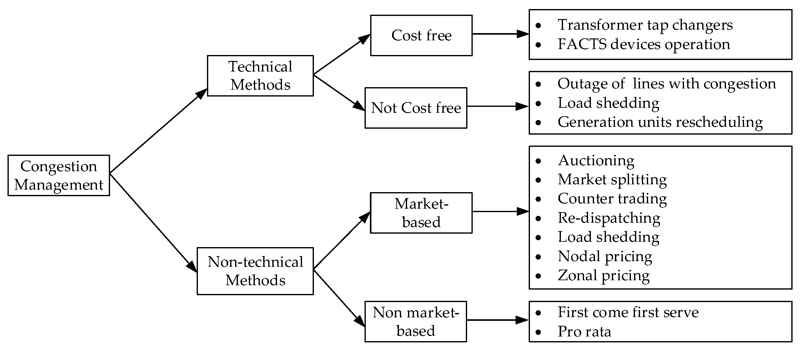
Congestion management is the process of making use of available power system infrastructure (economical and operational) while operating within system constraints [41]. Congestion management gives long-term investment signals to the TSO for strengthening local (to a single TSO) or cross-zonal (shared with other TSOs) transmission system infrastructure. A TSO responsible for a given control area or multiple TSOs responsible for the concerned control area must compensate the cost for remedial actions for congestion management [15]. A number of methods have been proposed for congestion management in [38,39,40,41,42,43], these can be broadly categorized into two methods i.e., technical and non-technical methods. Technical methods of congestion management can be cost free and not cost free [44]. Use of FACTS devices, phase-shifters, and transformer tap change for congestion management comes under cost free congestion management methods. These methods are readily available with the TSO, have limited economic impact and do not involve other stakeholders such as generation or distribution companies. Load shedding and rescheduling of generating units for the purpose of congestion management comes under not cost-free methods. Technical methods are ordered by the TSO. Non-technical congestion management methods can be market-based (auctioning, counter trading, nodal, or zonal pricing etc.) and non-market-based (pro rata or first come first serve). There is no involvement of TSO in non-technical congestion management methods and these are just observed by the TSO. Classification of various congestion management methods has been illustrated in Figure 3.
3. Ancillary Services in De-Regularized Electricity Market Context
Although ancillary services have been defined by ENTSO-E, the methods for procurement and implementation of these ancillary services vary across different control areas of ENTSO-E. A survey carried out by ENTSO-E on ‘ancillary services procurement, balancing market design 2018’ [11] shows that different EU member states have implemented the centrally defined ancillary services in very different manners. For instance, different balancing and ancillary services markets in EU member states have different market closing time for procurement of the ancillary services, different set of participants, different activation time (deadband before activation or instantaneous activation) and different procedure for recovering the cost of ancillary services. As an illustrative example, few features related to FRR (energy) ancillary services for balancing and ancillary services markets in Germany, Belgium, France and Norway are tabulated in Table 3. From this table it is clear that the ancillary services are different products in each of these countries, even when defined in a single grid code.
It has been set in [15] that each TSO must procure 30% FCR from within its load flow block. The volume for FRR and RR to be procured from within load flow block is 50%. A platform for primary and secondary control reserves has been established in Germany for sharing the reserves among the TSOs from Germany, France, Belgium, the Netherlands, Austria and Switzerland [46]. Such flexibility in procurement of services from other control areas gives the TSOs an economical opportunity and encourages the optimal use of inter-zonal transmission capacity. This flexibility of balancing and ancillary services markets has motivated the TSOs to enhance the cross-zonal or inter-country transmission capacities. While procuring the services from different control areas, care needs to be taken about various features of the offered service. From Table 3, it can be observed that the product resolution in time is 1 h for the FRR in balancing and ancillary services market in Germany whereas the same is 30 and 15 min for markets in France and Belgium, respectively. Therefore, to buy the same FRR from Belgian and French markets, a TSO must procure 4 and 2 products respectively as compared to 1 in balancing and ancillary services market in Germany.
4. HVDC Transmission Systems, Control and Dynamics
HVDC transmission systems are seen as a key enabler for bulk power transmission over long distances with better controllablity as compared to conventional AC systems. HVDC transmission systems can be asynchronous interconnection, embedded transmission line in synchronous system and offshore to onshore grid interconnections. Asynchronous HVDC interconnection is the connection between AC systems operating at different frequencies or systems operating at same frequency but different phase angles [47]. An example of such interconnection is NORNED HVDC link between Norway and the Netherlands. HVDC synchronous interconnection or embedded HVDC is the connection between two nodes in a synchronous area such as ALEGrO link between Belgium and Germany. For evacuation of bulk power from remotely located offshore windfarms, HVDC interconnections are becoming a preferred option. HVDC transmission link BorWin1 in Germany is an example of such system. The representative line diagrams of HVDC transmission systems for asynchronous, synchronous and offshore HVDC connection are shown in Figure 4a–c, respectively.
For HVDC converter stations two types of HVDC technologies are used namely Line commutated converter (LCC) which uses thyristors in current source converters(CSC) topology and voltage source converters (VSC) that uses gate turn-off thyristors (GTOs) or insulated gate bipolar transistors (IGBTs) [48] as shown in Figure 5a,b respectively. Both technologies have some advantages and disadvantages. LCC technology is a very mature technology, cheaper, has less converter station losses, more short-term overload capability and has higher converter ratings in comparison to VSC-based HVDC systems [12]. However, this technology requires large AC and DC harmonic filters, significant dependency of active and reactive power, no blackstart capability and requirement of strong connecting AC systems. It is complicated to use LCC-based technology when power reversal is frequently required because the voltage polarity needs to be changed to change direction of power flow [14]. LCC-based HVDC systems are normally used for back-to-back or point-to-point interconnection of asynchronous systems [49]. VSC-based HVDC technology is relatively new and can be used to control both active and reactive power separately. This technology can provide AC voltage to blacked-out grids and provide reactive power support similar to statcom [14]. VSC converters are smaller due to requirement of smaller filters [12] and more dynamic in particular with respect to power reversal. VSC-based technology is considered to be a better choice for multi-terminal HVDC grids.
Interactions between HVDC systems and AC systems have increased due to the increasing number of HVDC systems. A control structure as per Figure 6 has been proposed in [50] to highlight the similarities for primary, secondary, and tertiary control for HVDC and AC system using well known power system interaction between lower controllers and power dispatch.
It is expected that HVDC systems shall also participate in ensuring secure power system control and operation. A converter control for VSC-based HVDC systems as illustrated in Figure 7 [51,52] is generally used for controlling the firing of the IGBTs to control the HVDC grid and AC system voltage. The active power balance in the HVDC system is reflected by the DC voltage in a manner similar to frequency in the AC system [12]. Active power-DC voltage control in the DC system is therefore similar to active power-frequency control in AC systems. Furthermore, it is possible to implement active power and reactive power droop control from the converter stations by controlling the values and as shown in Figure 8a,b, respectively. However, as mentioned earlier for LCC-based HVDC systems it is not possible to control reactive power independent of active power and extra reactive power compensation is required to change reactive power independently [14]. and in Figure 8a,b are the active power-dc voltage and reactive power-ac voltage droop coefficients respectively.
It is also possible to incorporate AC system frequency-active power droop to make the converter react to the frequency deviations in the AC system. The control diagram is presented in Figure 9. in Figure 9 is the frequency-active power droop coefficients.
In contrast to AC systems which have large inertia, the DC systems have negligible inertia (only small amount of energy is stored in cables and capacitors). A consequence of this small inertia is that the DC systems respond faster to system imbalances than AC systems [54]. An overview of time constants associated with various services for AC and DC systems is presented in Figure 10.
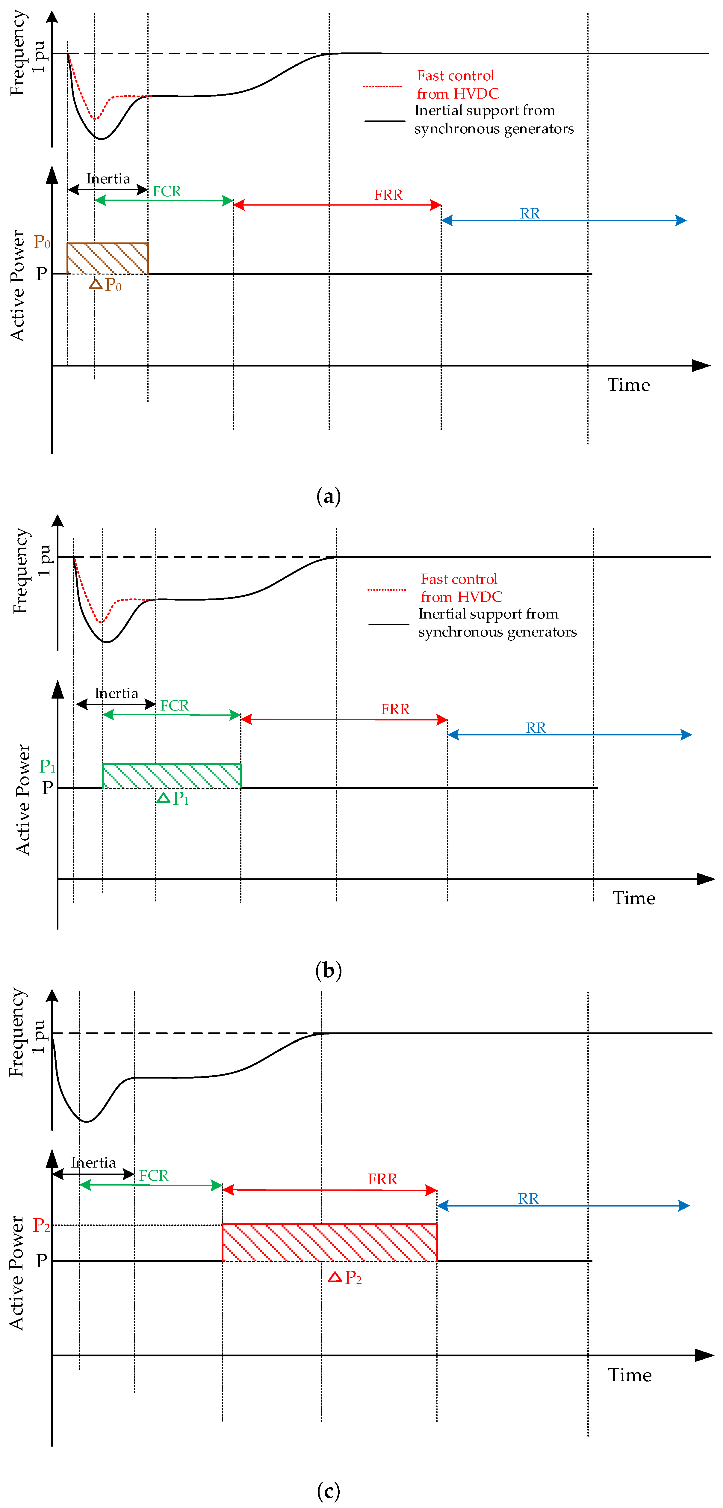
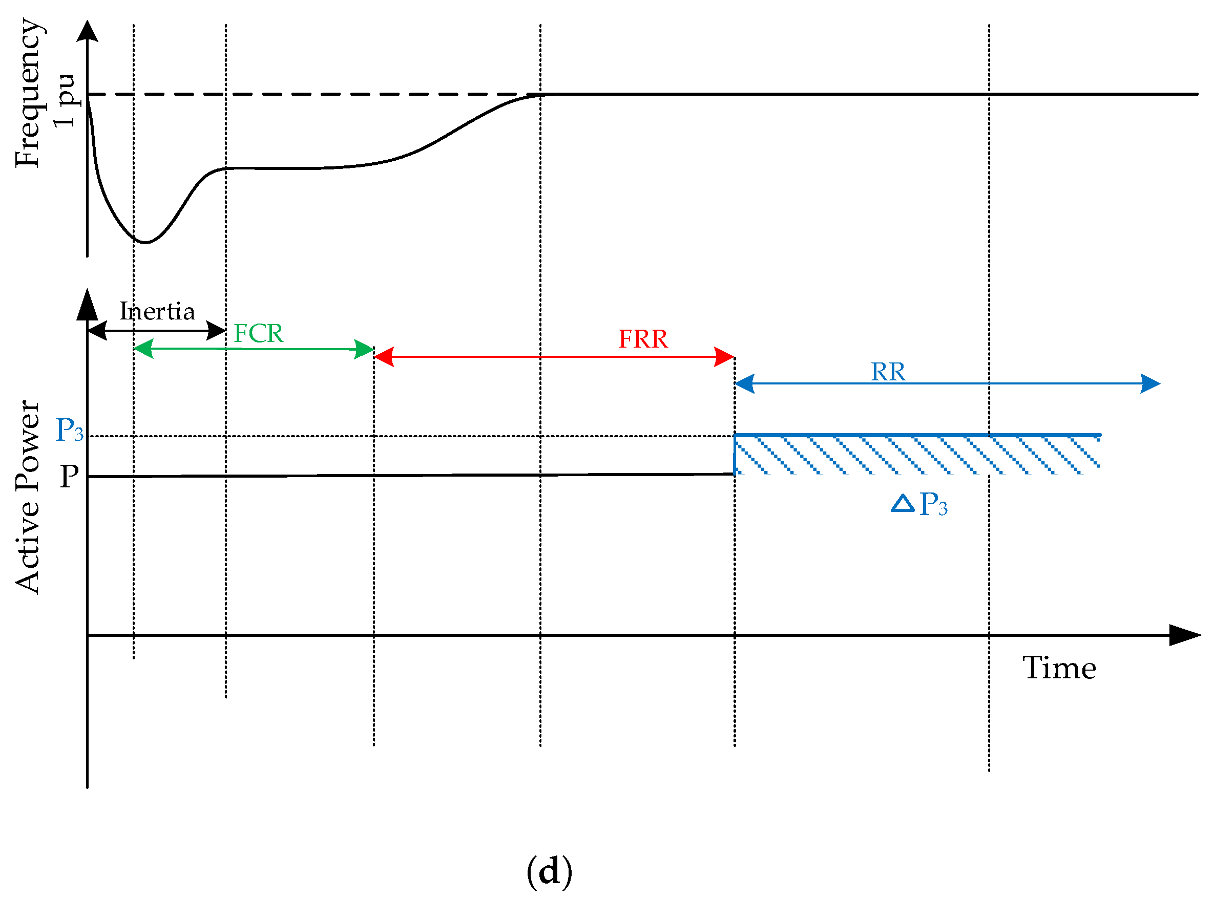
As stated earlier, DC voltage in HVDC systems plays the same role as frequency in the AC systems and can be considered to be an indicator of stable grid operation. Hence, active power imbalances can be controlled by controlling the DC voltage. It can be observed from Figure 10 that the activation time of DC equipments is two orders of magnitude lower than AC system equipments. Primary DC voltage control is activated much faster than FCR and it can play a similar role of inertia support (if frequency-based active power droop is implemented). Using HVDC for frequency control also results in improvement of frequency nadir [55]. It has been concluded in [56] that combining the frequency control reserves (among CE, Nordic and GB systems) using HVDC systems improves ROCOF, frequency nadir, and frequency quality. It can be deduced from these studies that HVDC systems can be an alternative to provide frequency support in the manner which is equivalent to inertia support. Various scenarios for providing frequency support (inertia, FCR, FRR and RR) by providing required active power from HVDC interconnections are shown in Figure 11. It is pertinent to mention here that inertia support and FCR can only be provided by asynchronous or offshore windfarm HVDC interconnections and cannot be provided by the HVDC connections embedded in synchronous zone (as HVDC systems do not store/generate power themselves and the additional power comes from other generation sources). It is possible to provide FRR and RR using synchronous HVDC systems by making remote generation units contribute by changing their set points. It is not possible to provide blackstart using HVDC systems independent of other AC system as some power source is required.
5. Ancillary Services and HVDC Systems
As mentioned in Section 3, liberalized electricity markets and integration of remote renewable energy sources have highlighted the need for enhanced cross-zonal transmission capacity among various European countries. HVDC transmission systems seems to be the most viable solution for cross-zonal interconnection as these can carry more power and have better controllability. Also, for integrating offshore renewables generation HVDC systems are being preferred. It will not be an over statement that in near future the DC elements will play an important role in power system management. Guidelines have also been published for participation of HVDC systems in power system operation support in ENTSO-E area [57]. For instance, the guidelines allows the TSO to require the HVDC system to control the active (and reactive) power output to maintain stable AC system frequency, provide synthetic inertia in event of frequency deviation in the connected AC system and remain connected and in operation if the network frequency changes at a rate from −2.5 to +2.5 Hz/s.
HVDC systems can actively participate in providing ancillary services to AC systems [14] as detailed in Section 4 also. At the same time HVDC systems will also need ancillary services such as energy balance, loss compensation, black start and restoration for smooth operation [12]. In [58], the capability of windfarms connected through HVDC to provide ancillary services to DC systems has been presented. The aspects of ancillary services required by HVDC systems are not further covered in this paper.
Based on the requirements of ancillary services for AC system, research has been going on to develop the possible solution for providing the ancillary services from HVDC systems to AC systems and in the literature several possible solutions have been proposed. The literature review of possible methods for ancillary services provisions from LCC-based and VSC-based HVDC systems is presented below:
- i
- LCC-based HVDC system: The authors in [59,60,61,62] have proposed some approaches to control the system voltage from LCC-based HVDC systems. Voltage stability analysis for multi-feed HVDC system using STATCOM has been presented by authors in [63]. Various methods for providing frequency control service from such HVDC systems are presented in [64,65]. In [66], the authors have proposed virtual synchronous generators (VSG) approach for providing frequency control from islanded windfarms. Methods for providing blackstart service with LCC-based HVDC systems has been detailed in [67,68]. Methods for power oscillation damping using LCC-based HVDC systems for connected AC systems are detailed in [62,69,70].
- ii
- VSC-based HVDC system: In [71,72], the authors have proposed VSG approach for providing fast frequency control and virtual inertia from the VSC-based HVDC converter stations. Fast frequency and AC system voltage control has been proposed by the authors in [73]. For providing primary frequency support (FCR) from offshore windfarms, HVDC converter control techniques have been proposed in [74,75,76,77,78]. In [59,79,80,81], the authors have discussed the provisions for AC system voltage control service from HVDC systems. The method for providing frequency from the energy stored in HVDC link is highlighted in [82]. The authors in [83,84,85] have presented the various studies on blackstart capabilities of VSC-based HVDC systems. In [86,87,88,89,90], the authors have highlighted the control aspects for oscillation damping for VSC-based HVDC systems.
Based on the literature review, some of distinctive features of HVDC systems and their possible use for providing ancillary services have been summarized in Table 4. It is assumed that sufficient reserves are available in the systems to provide the considered ancillary services.
6. Conclusions
Ancillary services play a pivotal role in ensuring reliable power system operation. It is critical that various power system equipments which can provide these services could be used in an economical way while enabling smooth power system operation. This review paper details the definitions of ancillary services, procurement, and activation practices for these services as followed in different control areas of ENTSO-E. It can be concluded from this study that every control area in ENTSO-E follows its own practice for procurement and activation of ancillary services, despite these services being defined by one grid code.
A major outcome of this review paper is the significant potential of HVDC systems (specially VSC-based) in providing ancillary services. A comprehensive analysis of possible control methods and time frame of activation of HVDC equipments highlights the robustness and fast control aspects of HVDC systems. These characteristics are the major drivers for considering ancillary service support from HVDC systems especially within the context of an interconnected grid and offshore grids. From the comparative analysis for different HVDC systems it can be inferred that VSC-based HVDC systems can provide ancillary services in a manner better than or similar to that of the conventional AC systems. This analysis expands on the features of HVDC connections types in providing different ancillary services based on a literature review.
To facilitate the sharing of ancillary services from HVDC among different operators of an interconnected system, a coordinated evaluation of the most optimal use of ancillary services on pan-European level would be necessary. The categorization of different ancillary services from HVDC systems and their characteristics as presented in this paper, could be a starting point for such analysis.
Funding
This work is supported by the project HVDC Inertia Provision (HVDC Pro), financed by the ENERGIX program of the Research Council of Norway (project number 268053/E20) and the industry partners; Statnett, Equinor, RTE, and ELIA. https://www.sintef.no/en/projects/hvdc-inertia-provision/.
Conflicts of Interest
The authors declare no conflict of interest.
References
- Rebours, Y.G.; Kirschen, D.S.; Trotignon, M.; Rossignol, S. A Survey of Frequency and Voltage Control Ancillary Services—Part I: Technical Features. IEEE Trans. Power Syst. 2007, 22, 350–357. [Google Scholar] [CrossRef]
- Australian Energy Market Operator: Ancillary Services. Available online: https://www.aemo.com.au/Electricity/National-Electricity-Market-NEM/Security-and-reliability/Ancillary-services (accessed on 9 September 2019).
- PJM: Ancillary Services Market: Reserves. Available online: https://learn.pjm.com/three-priorities/buying-and-selling-energy/ancillary-services-market/reserves.aspx (accessed on 9 September 2019).
- PJM: Ancillary Services Market. Available online: https://learn.pjm.com/three-priorities/buying-and-selling-energy/ancillary-services-market.aspx (accessed on 9 September 2019).
- California ISO: Market Operations: Market Processes. Available online: http://www.caiso.com/market/Pages/MarketProcesses.aspx (accessed on 9 September 2019).
- AEMO: Guide to Ancillary Services in the National Electricity Market. Available online: https://www.aemo.com.au/-/media/Files/PDF/Guide-to-Ancillary-Services-in-the-National-Electricity-Market.pdf (accessed on 9 September 2019).
- Official Journal of the European Union: Commission Regulation(EU) 2017/2195 of 23 November 2017 Establishing a Guideline on Electricity Balancing. Available online: https://eur-lex.europa.eu/legal-content/EN/TXT/PDF/?uri=CELEX:32017R2195&from=GA (accessed on 9 September 2019).
- Australian Energy Market Operator: Non-Market Ancillary Services. Available online: https://www.aemo.com.au/-/media/Files/Electricity/NEM/Security_and_Reliability/Power_System_Ops/Procedures/SO_OP_3708---Non-market-Ancillary-Services.pdf (accessed on 9 September 2019).
- ANEXT: KRAFTWERKE: Balancing Markets. Available online: https://www.next-kraftwerke.be/en/knowledge-hub/balancing-markets/ (accessed on 9 September 2019).
- ENTSO-E: Balancing and Ancillary Services Markets. Available online: https://www.entsoe.eu/about/market/#balancing-and-ancillary-services-markets (accessed on 9 September 2019).
- Survey on Ancillary Services Procurement, Balancing Market Design 2018 by ENTSO-E WGAS, March 2019. Available online: https://www.entsoe.eu/publications/market-reports/#survey-on-ancillary-services-procurement-and-electricity-balancing-market-design (accessed on 9 September 2019).
- Van Hertem, D.; Robert, H.; Renner, R.H.; Johan Rimez, J. Chapter 10—Power system operation with HVDC grids. In HVDC Grids For Offshore and Supergrid of the Future; Van Hertem, D., Gomis-Bellmunt, O., Liang, J., Eds.; IEEE Press Series on Power Engineering; John Wiley & Sons: Hoboken, NJ, USA, 2016; pp. 230–235. ISBN 978-1-118-85915-5. [Google Scholar]
- ENTSO-E. Requirements for Grid Connection Applicable to All Generators; Technical Report; ENTSO-E: Brussels, Belgium, 2013. [Google Scholar]
- Renner, R.H.; Van Hertem, D. Ancillary services in electric power systems with HVDC grids. IET Gener. Transm. Distrib. 2015, 9, 1179–1185. [Google Scholar] [CrossRef]
- Official Journal of the European Union: Commission Regulation(EU) 2017/1485 of 2 August 2017 Establishing a Guideline on Electricity Transmission System Operation. Available online: https://eur-lex.europa.eu/legal-content/EN/TXT/PDF/?uri=CELEX:32017R1485&from=EN (accessed on 9 September 2019).
- Kirschen, D.S.; Strbac, G. Chapter 5—System security and ancillary services. In Fundamental of Power System Ecconomics; John Wiley & Sons Ltd.: Chichester, UK, 2004; pp. 105–139. ISBN 0-470-84572-4. [Google Scholar]
- Tielens, P.; Van Hertem, D. The relevance of inertia in power systems. Renew. Sustain. Energy Rev. 2016, 55, 999–1009. [Google Scholar] [CrossRef]
- Future System Inertia: ENTSO-E Report. Available online: https://docstore.entsoe.eu/Documents/Publications/SOC/Nordic/Nordic_report_Future_System_Inertia.pdf (accessed on 9 September 2019).
- Future Ancillary Services in ERCOT. ERCOT concept paper, Draft version 1.0, 2013. Available online: https://www.ferc.gov/CalendarFiles/20140421084800-ERCOT-ConceptPaper.pdf (accessed on 9 September 2019).
- Need for Synthetic Inertia (SI) for Frequency Regulation: ENTSO-E Guidance Document for National Implementation for Network Codes on Grid Connection 2 November 2017. Available online: https://consultations.entsoe.eu/system-development/entso-e-connection-codes-implementationguidance-d-4/user_uploads/6---igd-on-si.pdf (accessed on 9 September 2019).
- Beerten, J. Chapter 15—Control Principles of HVDC Grids. In HVDC Grids For Offshore and Supergrid of the Future; Van Hertem, D., Gomis-Bellmunt, O., Liang, J., Eds.; IEEE Press Series on Power Engineering; John Wiley & Sons: Hoboken, NJ, USA, 2016; pp. 315–331. ISBN 978-1-118-85915-5. [Google Scholar]
- Elia Product Desciption for Ancillary Services. Available online: http://www.elia.be/en/suppliers/purchasing-categories/energy-purchases/Ancillary-services/Product-Description (accessed on 9 September 2019).
- Final Report on “Qualitative Analysis of Cross-Border Exchange of Balancing Energy and Operational Reserves between Netherlands and Belgium”; DNV KEMA Energy & Sustainability: Bonn, Germany, August 2013.
- Renner, R.H. Interaction of HVDC Grids and AC Power Systems Operation and Control. Ph.D. Thesis, KU Leuven, Leuven, Belgium, 2016. [Google Scholar]
- Knight, U.G. Power Systems in Emergencies: From Contingency Planning to Crisis Management; John Wiley & Sons: Hoboken, NJ, USA, 2001; ISBN 978-0-471-49016-6. [Google Scholar]
- Pentayya, P.; Gartia, A.; Das, A.P.; Kumar, C. Black Start Exercises Experience in Western Region, India. In Proceedings of the 2013 Annual IEEE India Conference (INDICON), Mumbai, India, 13–15 December 2013; pp. 1–5. [Google Scholar] [CrossRef]
- Sun, W.; Liu, C.; Zhang, L. Optimal Generator Start-Up Strategy for Bulk Power System Restoration. IEEE Trans. Power Syst. 2011, 26, 1357–1366. [Google Scholar] [CrossRef]
- Saraf, N.; McIntyre, K.; Dumas, J.; Santoso, S. The Annual Black Start Service Selection Analysis of ERCOT Grid. IEEE Trans. Power Syst. 2009, 24, 1867–1874. [Google Scholar] [CrossRef]
- Elia pRoduct Desciption for Ancillary Services-Voltage and Reactive Power Control. Available online: http://www.elia.be/~/media/files/Elia/Products-and-services/ProductSheets/S-Ondersteuning-net/S6_EN_2016.pdf (accessed on 9 September 2019).
- IEEE Recommended Practice for Excitation System Models for Power System Stability Studies; IEEE Std 421.5-2005 (Revision of IEEE Std 421.5-1992); IEEE: Piscataway, NJ, USA, 2006; pp. 1–93. [CrossRef]
- Corsi, S. Voltage Control and Protection in Electrical Power Systems—From System Components to Wide-Area Control; Springer: London, UK, 2015; pp. 163–190. ISBN 978-1-4471-6636-8. [Google Scholar]
- Panda, S. Multi-objective evolutionary algorithm for SSSC-based controller design. Electric Power Syst. Res. 2009, 79, 937–944. [Google Scholar] [CrossRef]
- Mithulananthan, N.; Canizares, C.A.; Reeve, J.; Rogers, G.J. Comparison of PSS, SVC, and STATCOM controllers for damping power system oscillations. IEEE Trans. Power Syst. 2003, 18, 786–792. [Google Scholar] [CrossRef]
- Dominguez-Garcia, J.L.; Ugalde-Loo, C.E. Chapter 19—Power System Oscillation damping by means of VSC-HVDC systems. In HVDC Grids For Offshore and Supergrid of the Future; Van Hertem, D., Gomis-Bellmunt, O., Liang, J., Eds.; IEEE Press Series on Power Engineering; John Wiley & Sons: Hoboken, NJ, USA, 2016; pp. 315–331. ISBN 978-1-118-85915-5. [Google Scholar]
- Klein, M.; Rogers, G.J.; Kundur, P. A fundamental study of inter-area oscillations in power systems. IEEE Trans. Power Syst. 1991, 6, 914–921. [Google Scholar] [CrossRef]
- Larsen, E.V.; Sanchez-Gasca, J.J.; Chow, J.H. Concepts for design of FACTS controllers to damp power swings. IEEE Trans. Power Syst. 1995, 10, 948–956. [Google Scholar] [CrossRef]
- Kumar, A.; Srivastava, S.C.; Singh, S.N. A zonal congestion management approach using real and reactive power rescheduling. IEEE Trans. Power Syst. 2004, 19, 554–562. [Google Scholar] [CrossRef]
- Yusoff, N.I.; Zin, A.A. Congestion Management in Power Systems—A review. In Proceedings of the 3rd International Conference on Power Generation Systems and Renewable Energy Technologies (PGSRET), Johor Bahru, Malaysia, 4–6 April 2017; pp. 22–27. [Google Scholar] [CrossRef]
- Official Journal of the European Union: Commission Regulation(EU) 2015/1222 of 24 July 2015 Establishing a Guideline on Capacity Allocation and Congestion Management. Available online: https://eur-lex.europa.eu/legal-content/EN/TXT/PDF/?uri=CELEX:32015R1222&from=EN (accessed on 9 September 2019).
- CREG Paper (Z)1847: Paper on the Belgian Day-Ahead Wholesale Electricity Market from 1 to 7 October 2018, Focusing on the Market Outcomes for 3 October 2018. Available online: https://www.creg.be/sites/default/files/assets/Publications/Notes/Z1847EN.pdf (accessed on 9 September 2019).
- Emami, H.; Sadri, J.A. Congestion management of transmission lines in the market environment. Int. Res. J. Appl. Basic Sci. 2012, 3, 2572–2580. [Google Scholar] [CrossRef]
- Singh, N.; David, A.K. Towards dynamic security-constrained congestion management in open power market. IEEE Power Eng. Rev. 2000, 20, 45–47. [Google Scholar] [CrossRef]
- Yousefi, A.; Nguyen, T.T.; Zareipour, H.; Malik, O.P. Congestion management using demand response and FACTS devices. Int. J. Electr. Power Energy Syst. 2012, 37, 78–85. [Google Scholar] [CrossRef]
- Pillay, A.; Karthikeyan, S.P.; Kothari, D.P. Congestion management in power systems—A review. Int. J. Electr. Power Energy Syst. 2015, 70, 83–90. [Google Scholar] [CrossRef]
- Mwanza, K.; Shi, Y. Congestion Management: Re-Dispatch and Application of Facts. Master’s Thesis, Department of Energy and Environment, Chalmers University of Technology, Goteborg, Sweden, 2006. [Google Scholar]
- Regelleistung Website. Available online: https://www.regelleistung.net (accessed on 9 September 2019).
- Wang, H.; Redfern, M.A. The advantages and disadvantages of using HVDC to interconnect AC networks. In Proceedings of the 45th International Universities Power Engineering Conference UPEC, Cardiff, Wales, UK, 31 August–3 September 2010; pp. 1–5. [Google Scholar]
- Flourentzou, N.; Agelidis, V.G.; Demetriades, G.D. VSC-Based HVDC Power Transmission Systems: An Overview. IEEE Trans. Power Electron. 2009, 24, 592–602. [Google Scholar] [CrossRef]
- ENTSO-E report on Technologies for Transmission Systems. Available online: https://tyndp.entsoe.eu/2016/insight-reports/technology/#line-commutated-converter-lcc-technology (accessed on 9 September 2019).
- Egea-Alvarez, A.; Beerten, J.; Van Hertem, D.; Gomis-Bellmunt, O. Primary and secondary power control of multiterminal HVDC grids. In Proceedings of the IET International Conference on AC and DC Power Transmission, Birmingham, UK, 4–5 December 2012; pp. 1–6. [Google Scholar] [CrossRef]
- Egea-Alvarez, A.; Junyent-Ferre, A.; Gomis Bellmunt, O. Modeling and Control of Sustainable Power Systems: Towards Smarter and Greener Electric Grids; Series: Green energy and technology; Springer: Berlin, Germany, 2012; pp. 47–81. [Google Scholar]
- Beerten, J.; Diaz, G.B.; D’Arco, S.; Suul, J.A. Comparison of small-signal dynamics in MMC and two-level VSC HVDC transmission schemes. In Proceedings of the IEEE International Energy Conference (ENERGYCON), Leuven, Belgium, 4–8 April 2016; pp. 1–6. [Google Scholar] [CrossRef]
- Loh, P.C.; Li, D.; Chai, Y.K.; Blaabjerg, F. Autonomous Operation of Hybrid Microgrid with AC and DC Subgrids. IEEE Trans. Power Electron. 2013, 28, 2214–2223. [Google Scholar] [CrossRef]
- Beerten, J.; Gomis-Bellmunt, O.; Guillaud, X.; Rimez, J.; van der Meer, A.; Van Hertem, D. Modeling and control of HVDC grids: A key challenge for the future power system. Power Syst. Comput. Conf. 2014, 1–21. [Google Scholar] [CrossRef] [Green Version]
- Kou, P.; Liang, D.; Wu, Z.; Ze, Q.; Gao, L. Frequency Support From a DC-Grid Offshore Wind Farm Connected Through an HVDC Link: A Communication-Free Approach. IEEE Trans. Energy Convers. 2018, 33, 1297–1310. [Google Scholar] [CrossRef]
- De Haan, J.E.S.; Concha, C.E.; Gibescu, M.; van Putten, J.; Doorman, G.L.; Kling, W.L. Stabilising system frequency using HVDC between the Continental European, Nordic, and Great Britain systems. Sustain. Energy Grids Netw. 2016, 5, 125–134. [Google Scholar] [CrossRef]
- Official Journal of the European Union: Commission Regulation(EU) 2016/1447 of 26 August 2016 Establishing a Network Code on Requirements for Grid Connection of High Voltage Direct Current Systems and Direct Current-Connected Power Park Modules. Available online: https://eur-lex.europa.eu/legal-content/EN/TXT/PDF/?uri=CELEX:32016R1447&from=EN (accessed on 9 September 2019).
- Renner, R.H.; Van Hertem, D. Potential of Wind Farms Connected to HVdc Grid to Provide DC Ancillary Services. IEEE Trans. Sustain. Energy 2018, 9, 1011–1020. [Google Scholar] [CrossRef]
- Xue, Y.; Zhang, X. Reactive Power and AC Voltage Control of LCC HVDC System with Controllable Capacitors. IEEE Trans. Power Syst. 2017, 32, 753–764. [Google Scholar] [CrossRef]
- Yin, H.; Fan, L.; Miao, Z. Fast Power Routing Through HVDC. IEEE Trans. Power Deliv. 2012, 27, 1432–1441. [Google Scholar] [CrossRef]
- Liu, H.; Sun, J. Small-signal stability analysis of offshore wind farms with LCC HVDC. In Proceedings of the 2013 IEEE Grenoble Conference, Grenoble, France, 16–20 June 2013; pp. 1–8. [Google Scholar] [CrossRef]
- Azad, S.P.; Taylor, J.A.; Iravani, R. Decentralized Supplementary Control of Multiple LCC-HVDC Links. IEEE Trans. Power Syst. 2016, 31, 572–580. [Google Scholar] [CrossRef]
- Saichand, K.; Padiyar, K.R. Analysis of voltage stability in multi-infeed HVDC systems with STATCOM. In Proceedings of the 2012 IEEE International Conference on Power Electronics, Drives and Energy Systems (PEDES), Bengaluru, India, 16–19 December 2012; pp. 1–6. [Google Scholar] [CrossRef]
- Kaur, J.; Yogarathinam, A.; Chaudhuri, N.R. Frequency control for weak AC grid connected to wind farm and LCC-HVDC system: Modeling and stability analysis. In Proceedings of the IEEE Power and Energy Society General Meeting (PESGM), Boston, MA, USA, 17–21 July 2016; pp. 1–5. [Google Scholar] [CrossRef]
- Fan, L.; Miao, Z.; Osborn, D. Wind Farms With HVDC Delivery in Load Frequency Control. IEEE Trans. Power Syst. 2009, 24, 1894–1895. [Google Scholar] [CrossRef]
- He, X.; Geng, H.; Yang, G.; Zou, X. VSG Control for DFIG-based Islanded Wind Farm with LCC-HVDC Integration. In Proceedings of the IEEE Power & Energy Society General Meeting (PESGM), Portland, OR, USA, 5–10 August 2018; pp. 1–5. [Google Scholar] [CrossRef]
- Xue, Y.; Yang, C.; Zhang, X. Investigation of black start capability of LCC HVDC system with controllable capacitors. In Proceedings of the 12th IET International Conference on AC and DC Power Transmission (ACDC 2016), Beijing, China, 28–29 May 2016; pp. 1–6. [Google Scholar] [CrossRef]
- Andersson, M.; Cai, R.; Yang, C. Black start of a passive AC network using bipolar LCC HVDC. In Proceedings of the 3rd Annual Conference of HVDC and Power Electronics Special Committee, Wuhan, China, 29 October–1 November 2014. [Google Scholar]
- Azad, S.P.; Iravani, R.; Tate, J.E. Stability Enhancement of a DC-Segmented AC Power System. IEEE Trans. Power Deliv. 2015, 30, 737–745. [Google Scholar] [CrossRef]
- Rauhala, T.; Järventausta, P. On feasibility of SSDC to improve the effect of HVDC on subsynchronous damping on several lower range torsional oscillation modes. In Proceedings of the IEEE PES General Meeting, Providence, RI, USA, 25–29 July 2010; pp. 1–8. [Google Scholar] [CrossRef]
- Driesen, J.; Visscher, K. Virtual synchronous generators. In Proceedings of the IEEE Power and Energy Society General Meeting—Conversion and Delivery of Electrical Energy in the 21st Century, Pittsburgh, PA, USA, 20–24 July 2008; pp. 1–3. [Google Scholar] [CrossRef]
- D’Arco, S.; Suul, J.A.; Fosso, O.B. Small-Signal Modeling and Parametric Sensitivity of a Virtual Synchronous Machine in Islanded Operation. Int. J. Electr. Power Energy Syst. 2015, 72, 3–15. [Google Scholar] [CrossRef]
- Musa, A.; Kaushal, A.; Gurumurthy, S.K.; Raisz, D.; Ponci, F.; Monti, A. Development and Stability Analysis of LSD-Based Virtual Synchronous Generator for HVDC Systems. In Proceedings of the 44th Annual Conference of the IEEE Industrial Electronics Society, Washington, DC, USA, 21–23 October 2018; pp. 3535–3542. [Google Scholar] [CrossRef]
- Hughes, F.M.; Anaya-Lara, O.; Jenkins, N.; Strbac, G. Control of DFIG-based wind generation for power network support. IEEE Trans. Power Syst. 2005, 20, 1958–1966. [Google Scholar] [CrossRef]
- Ullah, N.R.; Thiringer, T.; Karlsson, D. Temporary Primary Frequency Control Support by Variable Speed Wind Turbines—Potential and Applications. IEEE Trans. Power Syst. 2008, 23, 601–612. [Google Scholar] [CrossRef]
- Keung, P.; Li, P.; Banakar, H.; Ooi, B.T. Kinetic Energy of Wind-Turbine Generators for System Frequency Support. IEEE Trans. Power Syst. 2009, 24, 279–287. [Google Scholar] [CrossRef]
- Vidyanandan, K.V.; Senroy, N. Primary frequency regulation by deloaded wind turbines using variable droop. IEEE Trans. Power Syst. 2013, 28, 837–846. [Google Scholar] [CrossRef]
- Tavakoli, M.; Pouresmaeil, E.; Adabi, J.; Godina, R.; Catalão, J.P.S. Load-frequency control in a multi-source power system connected to wind farms through multi terminal HVDC systems. Comput. Oper. Res. 2018, 96, 305–315. [Google Scholar] [CrossRef]
- Li, S.; Haskew, T.A.; Xu, L. Control of HVDC Light System Using Conventional and Direct Current Vector Control Approaches. IEEE Trans. Power Electron. 2010, 25, 3106–3118. [Google Scholar] [CrossRef]
- Rabiee, A.; Soroudi, A.; Keane, A. Risk-Averse Preventive Voltage Control of AC/DC Power Systems Including Wind Power Generation. IEEE Trans. Sustain. Energy 2015, 6, 1494–1505. [Google Scholar] [CrossRef]
- Li, Z.; He, Y.; Li, Y.; Gu, W.; Tang, Y.; Zhang, X. Hybrid Control Strategy for AC Voltage Stabilization in Bipolar VSC-MTDC. IEEE Trans. Power Syst. 2019, 34, 129–139. [Google Scholar] [CrossRef]
- Junyent-Ferr, A.; Pipelzadeh, Y.; Green, T.C. Blending HVDC-Link Energy Storage and Offshore Wind Turbine Inertia for Fast Frequency Response. IEEE Trans. Sustain. Energy 2015, 6, 1059–1066. [Google Scholar] [CrossRef]
- Becker, H.; Naranovich, A.; Hennig, T.; Akbulut, A.; Mende, D.; Stock, S.; Hofmann, L. System restoration using VSC-HVDC connected offshore wind power plant as black-start unit. In Proceedings of the 19th European Conference on Power Electronics and Applications (EPE’17 ECCE Europe), Warsaw, Poland, 11–14 September 2017; pp. 1–8. [Google Scholar] [CrossRef]
- Macleod, N.; Cowton, N.; Egan, J. System restoration using the “black” start capability of the 500MW EIRGRID East- West VSC-HVDC interconnector. In Proceedings of the IET International Conference on Resilience of Transmission and Distribution Networks (RTDN), Birmingham, UK, 22–24 September 2015; pp. 1–5. [Google Scholar] [CrossRef]
- Li, L.; Zhou, M.; Li, S.; Li, Y. A New Method of Black Start Based on VSC-HVDC. In Proceedings of the International Conference on Computing, Control and Industrial Engineering, Wuhan, China, 5–6 June 2010; pp. 300–303. [Google Scholar] [CrossRef]
- Preece, R.; Milanović, J.V.; Almutairi, A.M.; Marjanovic, O. Damping of inter-area oscillations in mixed AC/DC networks using WAMS based supplementary controller. IEEE Trans. Power Syst. 2013, 28, 1160–1169. [Google Scholar] [CrossRef]
- Pipelzadeh, Y.; Chaudhuri, B.; Green, T.C. Control Coordination Within a VSC HVDC Link for Power Oscillation Damping: A Robust Decentralized Approach Using Homotopy. IEEE Trans. Control Syst. Technol. 2013, 21, 1270–1279. [Google Scholar] [CrossRef]
- D’Arco, S.; Suul, J.A.; Molinas, M. Implementation and analysis of a control scheme for damping of oscillations in VSC-based HVDC grids. In Proceedings of the 16th International Power Electronics and Motion Control Conference and Exposition, Antalya, Turkey, 21–24 September 2014; pp. 586–593. [Google Scholar] [CrossRef]
- Preece, R.; Almutairi, A.M.; Marjanovic, O.; Milanović, J.V. Damping of inter-area oscillations using WAMS based supplementary controller installed at VSC based HVDC line. In Proceedings of the IEEE Trondheim PowerTech, Trondheim, Norway, 19–23 June 2011; pp. 1–8. [Google Scholar] [CrossRef]
- Corsi, S.; Danelli, A.; Pozzi, M. Emergency-stability controls through HVDC links. In Proceedings of the IEEE Power Engineering Society Summer Meeting, Chicago, IL, USA, 21–25 July 2002; Volume 2, pp. 774–779. [Google Scholar] [CrossRef]
Figure 1.
Ancillary services classification.


Figure 3.
Congestion management classification [45].
Figure 3.
Congestion management classification [45].

Figure 4.
Line diagramfor (a) asynchronousHVDC transmission systeminterconnection (b) synchronous HVDC transmission system (embedded line) and (c) offshore HVDC transmission system.
Figure 4.
Line diagramfor (a) asynchronousHVDC transmission systeminterconnection (b) synchronous HVDC transmission system (embedded line) and (c) offshore HVDC transmission system.
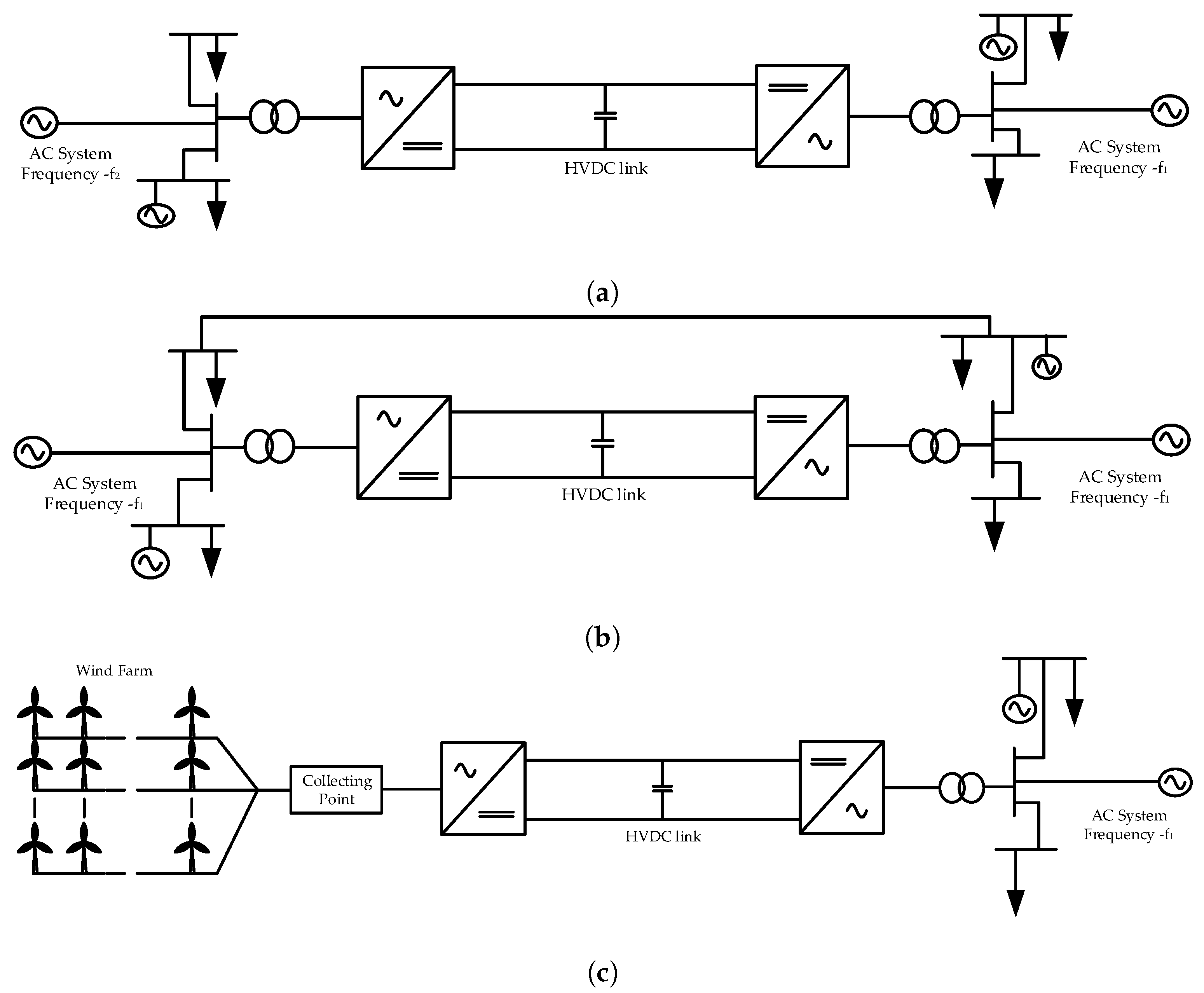
Figure 5.
(a) CSC and (b) VSC-based HVDC systems [48].
Figure 5.
(a) CSC and (b) VSC-based HVDC systems [48].

Figure 6.
Combined AC and DC control scheme [50].
Figure 6.
Combined AC and DC control scheme [50].
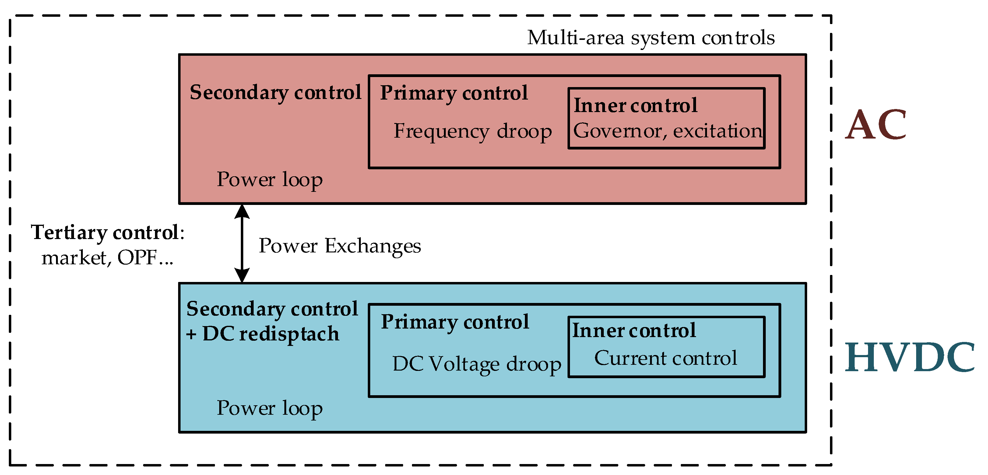
Figure 7.
Control scheme for VSC converter station.
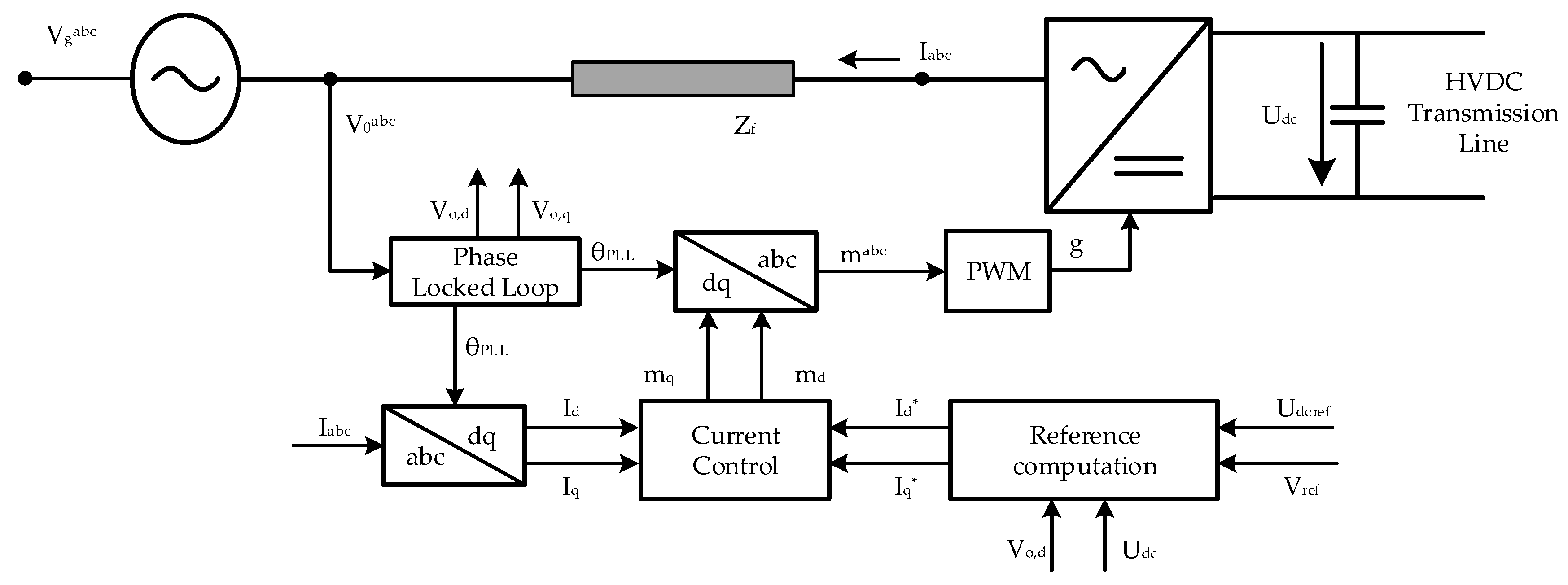
Figure 8.
Reference (a) DC voltage based on active power-DC voltage droop and (b) AC voltage based on reactive power-AC voltage droop.
Figure 8.
Reference (a) DC voltage based on active power-DC voltage droop and (b) AC voltage based on reactive power-AC voltage droop.

Figure 9.
AC system frequency-based active power-DC voltage droop control [53].
Figure 9.
AC system frequency-based active power-DC voltage droop control [53].

Figure 10.
Time constants for activation of services for AC & DC system elements [54].
Figure 10.
Time constants for activation of services for AC & DC system elements [54].
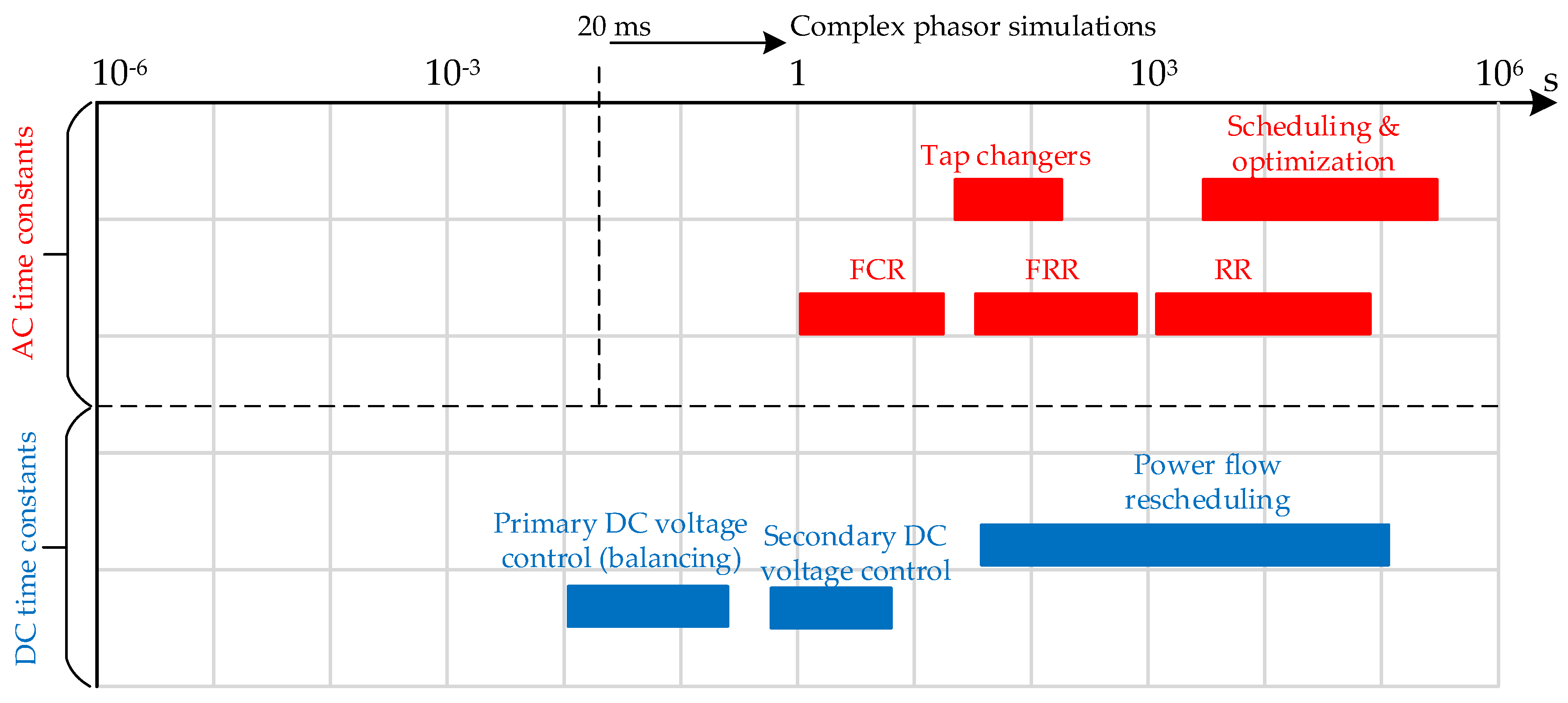
Figure 11.
Change in active power flow through HVDC transmission line for providing (a) inertia support, (b) frequency containment reserves, (c) frequency restoration reserves and (d) replacement reserves.
Figure 11.
Change in active power flow through HVDC transmission line for providing (a) inertia support, (b) frequency containment reserves, (c) frequency restoration reserves and (d) replacement reserves.

Table 1.
Frequency quality parameters [15].
Table 1.
Frequency quality parameters [15].
| Parameter | CE | GB | IE/NI | Nordic System |
|---|---|---|---|---|
| Standard frequency range (mHz) | ±50 | ±200 | ±200 | ±100 |
| Maximum instantaneous deviation (mHz) | 800 | 800 | 1000 | 1000 |
| Maximum steady-state deviation (mHz) | 200 | 500 | 500 | 500 |
Table 2.
Steady-state operational voltage range [15].
Table 2.
Steady-state operational voltage range [15].
| CE | Nordic | GB | IE & NI | Baltic | |
|---|---|---|---|---|---|
| Connection point voltage 110 kV–300 kV | |||||
| Voltage range (pu) | 0.9–1.118 | 0.9–1.05 | 0.9–1.10 | 0.9–1.118 | 0.9–1.118 |
| Connection point voltage 300 kV–400 kV | |||||
| Voltage range (pu) | 0.9–1.05 | 0.9–1.05 | 0.9–1.05 | 0.9–1.05 | 0.9–1.097 |
Table 3.
Frequency restoration reserve—balancing and ancillary services market implementation in 4 countries [11].
Table 3.
Frequency restoration reserve—balancing and ancillary services market implementation in 4 countries [11].
| Frequency Restoration Reserve—Energy | ||||
|---|---|---|---|---|
| Germany | Belgium | France | Norway | |
| Activation rule | Merit order | Pro rata | ||
| Procurement Scheme | Market only | Mandatory only | - | |
| Product Resolution (MW) | 1 < x ≤ 5 | x ≤ 1 | no minimum bid size | - |
| Product Resolution (in time) | 1 h | 15 min | 30 min | - |
| Distance to real time for auction | x ≤ 1 min | 5 < x ≤ 15 min | - | |
| Provider | Generators + load + pump storage | Generators+ pump storage | Generators | |
| Activation time (0 to max) | 90 s < x ≤ 5 min | 5 min < x ≤ 15 min | 90 s < x ≤ 5 min | |
| Settlement rule | Bid price | - | Marginal price | |
| Cost Recovery Scheme | Balance responsible party | Grid users | Balance responsible party | Grid users |
Table 4.
Ancillary Services from HVDC Transmission systems.
| System | Asynchronous | Synchronous | Offshore | Remarks | ||||
|---|---|---|---|---|---|---|---|---|
| Services | LCC Based | VSC Based | LCC Based | VSC Based | LCC Based | VSC Based | ||
| Inertia | NA | NA | VSC-based HVDC systems offer better controllability for offshore connections | |||||
| FCR | NA | NA | Synchronous zone embedded HVDC systems cannot provide Inertia and FCR | |||||
| FRR | NA | NA | HVDC systems provide better controllability as compared to AC systems | |||||
| RR | NA | NA | ||||||
| Voltage control | − | − | − | LCC-based HVDC systems cannot provide voltage control and Black start capability | ||||
| Black start | − | − | − | |||||
| Congestion Management | − | − | HVDC systems have better power carrying capability than AC systems | |||||
| Oscillation damping | + | + | VSC-based HVDC systems have better oscillation damping capabilities | |||||
Note. The symbol −, +, ++ and +++ means that the HVDC systems cannot provide the service, are able to provide the service, are able to provide the service similar to conventional AC systems and can provide the service better than AC systems respectively. * implies that the HVDC system requires appropriate controls at the offshore side to provide this service. NA implies that it is not possible to provide this service from respective HVDC system.
© 2019 by the authors. Licensee MDPI, Basel, Switzerland. This article is an open access article distributed under the terms and conditions of the Creative Commons Attribution (CC BY) license (http://creativecommons.org/licenses/by/4.0/).
Share and Cite
MDPI and ACS Style
Kaushal, A.; Van Hertem, D. An Overview of Ancillary Services and HVDC Systems in European Context. Energies 2019, 12, 3481. https://doi.org/10.3390/en12183481
AMA Style
Kaushal A, Van Hertem D. An Overview of Ancillary Services and HVDC Systems in European Context. Energies. 2019; 12(18):3481. https://doi.org/10.3390/en12183481
Chicago/Turabian StyleKaushal, Abhimanyu, and Dirk Van Hertem. 2019. "An Overview of Ancillary Services and HVDC Systems in European Context" Energies 12, no. 18: 3481. https://doi.org/10.3390/en12183481
Note that from the first issue of 2016, this journal uses article numbers instead of page numbers. See further details here.