Influence of the Dynamic Motion of a Splash-Lubricated Gearbox on Churning Power Losses

School of Mechanical and Electrical Engineering, State Key Laboratory of High Performance Complex Manufacturing, Central South University, Changsha 410083, China
*
Author to whom correspondence should be addressed.
Energies 2019, 12(17), 3225; https://doi.org/10.3390/en12173225
Submission received: 22 July 2019
/
Revised: 12 August 2019
/
Accepted: 19 August 2019
/
Published: 21 August 2019
(This article belongs to the Special Issue Engineering Fluid Dynamics 2019-2020)
Abstract
:To investigate the influence of the dynamic motion of a gearbox on lubricating flow field and churning power losses under splash lubrication, a computational fluid dynamics (CFD) method based on a combination of the fluid of volume (VOF) method and turbulence model is presented in this paper. A non-inertial coordinate system was employed to simulate the motion of the gearbox, and the feasibility and accuracy of the method was validated by the available experimental results. Numerical models of the gearbox with a spur gear pair under no load operation condition were established, and sinusoidal motions with different frequencies and amplitudes were implemented in the gearbox. The effects of the rotational speed of gears, oil immersion depth, and the frequency and amplitude of sinusoidal motions were studied. The results showed that the dynamic motion of the gearbox can exert a significant influence on churning losses and the oil supply of the gear contacting zone, and the gear pair may be in a loss-of-lubrication state.
1. Introduction
The efficiency of gear transmissions is an important study object in the field of energy-saving. The total energy losses in splash-lubricated gearboxes are mainly categorized in two ways the first are load dependent losses, which are a result of the inter-tooth meshing friction of gears and inter-surface friction of bearings and seals; the second category are independent of load and are known as churning power losses, which are losses due to the fluid resistance torque between the gear and the surrounding oil. When the rotational speeds of the gear speed is low, churning losses represent a tiny proportion of the total energy losses and can generally be ignored; however, several researchers have pointed out that when the gears rotate at higher speeds, the influence of the churning losses increases significantly. For example, Concli and Gorla [1] quoted Strasser’s investigations to show that in a parallel-shaft gearbox with splash lubrication, 70% of the total losses of gears is meshing friction loss and 30% is oil churning loss; Michaelis et al. [2] suggested that the no-load loss of rotating parts accounted for the majority of the overall loss of a gearbox under high-speed and light-load conditions; calculations by Neurouth et al. [3] showed that under high speed operating conditions (32,000 rpm), the gear churning loss is 1.28 times that of the meshing friction loss. Therefore, reducing churning losses can significantly improve the transmission efficiency of the gear transmission and effectively save energy; thus it is essential to accurately calculate the churning power losses of gear transmission.
Oil churning losses are generated by the combination of interactions between rotating gears and the surrounding oil, and the oil pumping effect between the meshing gear pair [4,5]. It is difficult to predict oil churning loss directly by theoretical methods, because its determination is affected by many factors, such as the complex inner shape of housing of gearboxes, flow field characteristics inside gearboxes, etc. [6,7,8,9].
In previous works, several researchers have performed experimental studies on oil churning losses inside gearboxes and presented analytical formulations under different assumptions [10,11,12]. Changenet and Velex [13] conducted several experiments on a specific test setup to study the influences of rotational speed, oil immersion depth, oil parameters and gear geometrical parameters, and derived a formula for calculating churning losses of spur gears. Höhn et al. [14] found that churning power losses can be significantly reduced with oil immersion depth. Seetharaman and Kahraman et al. [4,5] carried out experiments under different rotational speeds, temperatures, oil immersion depths and geometrical parameters of gears, and found that the static oil level and tooth width had important effects on the churning losses. Neurouth et al. [15] performed experiments to study the influence of air aeration phenomenon on churning losses and discovered that properly inserting movable walls inside the gearbox can significantly reduce air aeration and churning losses. Polly et al. [16] developed an experimental setup to study churning power losses with different operating parameters and geometrical parameters of gears and gear pair.
Continuous improvements in computer technology and CFD methods make it more reliable and effective to employ numerical methods to calculate churning losses of gears. Gorla et al. [17] built a CFD model to numerically investigate churning losses of power transmissions. Concli et al. [18], Concli and Gorla [19,20] used different and improved CFD modeling or simulation methods to predict no-load power losses of geared transmissions under varying operating and geometric parameters. Liu et al. [21] numerically calculated churning losses in a gearbox with a spur gear pair based on finite volume method, and observed good agreement between simulation results and experimental measures. Then, Liu et al. [22] also applied a smoothed particle hydrodynamics (SPH) method for the prediction of churning losses, but found that this method was not able to precisely calculate churning losses. Peng et al. [23] performed CFD simulations with a flank-moving method and obtained churning losses of a splash-lubricated hypoid gearbox. Jiang et al. [9] investigated the effect of an oil guide device on oil supply for bearings, and found churning power losses were not affected.
The above-mentioned studies reveal that churning power losses is significantly affected by oil flow behavior, and they pay most attention to on churning power losses of gearboxes in a static state, that is, the motion state of gearboxes was not often considered. However, in actual applications, a gearbox may be a part of movable objects, such as aircrafts, helicopters or vehicles, etc. Velocity, motion attitude and the direction of movement of those objects may change at any time, thus the motion state of the gearboxes are correspondingly dynamic changes, which cause the flow field inside gearboxes to be more complex and also to have an effect on churning power losses. Therefore, it is necessary to investigate the impact of the motion state of gearboxes on churning power losses. On this research topic, Lemfeld et al. [24] firstly performed CFD simulations to study the flow field of gearboxes under different inclined conditions, which resulted in varying angles of oil sump surface, and thus, obvious changes in splashing oil flow. Chen and Matsumoto et al. [25] developed a test setup to experimentally investigate churning losses of a spur gearbox considering the gearbox inclination and found that the inclination angle of gearboxes can exert an important influence on churning losses. Hu et al. [26] investigated the influence of the static tilt angle of the helicopter on the flow field and the churning losses, which showed that the flight attitude had a remarkable influence on churning power losses.
All of the previous studies have focused on the investigation of the internal oil distribution and churning losses of gearboxes in a static or quasi-stationary state, without considering the dynamic change of motion state, such as tilt angle, velocity, etc. However, in real working conditions, the motion state of gearboxes may change all the time, and the movement of gearboxes has an important influence on the internal flow field, and thus, churning power losses. Therefore, there is a strong demand to clearly reveal the influence mechanism of the motion state of gearboxes. In the present work, instead of employing a traditional CFD method, we establish CFD models based on the combination of a Fractional Area/Volume Obstacle Representation (FAVOR) method and a non-inertial coordinate system for realization of the dynamic motion of a gearbox. Second, the numerical approach is validated with available experimental results [25]. The effects of the rotational speed of gears, oil immersion depth and motion parameters of the gearbox on churning power losses are studied by CFD simulations.
2. Numerical Method
To study the effect of the dynamic motion of gearboxes on churning losses by numerical simulations, it is necessary to simultaneously simulate dynamic motion of gearboxes and gear pairs and precisely track the time-varying oil free surface inside gearboxes. To achieve this goal, a non-inertial coordinate system was used to simulate the motion of gearboxes, and the FAVOR method [27,28] was employed to model complex surfaces (for example, the gear meshing zone) in a size-fixed grid with two important parameters, namely, area fractions Ai and volume fractions VF, which describe the rotating gears at every time step and reconstruct the geometry according to the rotation of gears. Therefore, this method needs no body-fitted mesh, which can significantly improve calculation efficiency, and when in combination with the Volume of Fluid (VOF) method [29], it can precisely describe complex geometric shapes and capture oil free surfaces, which exactly meets the demand to solve problems in the present work.
In this paper, the Cartesian coordinate system was used to simulate the dynamic motion of the gearbox, and the lubricating oil was supposed to be a viscous incompressible fluid. The continuity equation can be given as:
where i = 1, 2, 3 represents x, y, and z directions, and is the area fraction.
The momentum equations for three-dimensional flows are Navier-Stokes (N-S) equations with some additional terms, which are given as follows:
where u, v and w are fluid velocity components, is the oil density, is the average pressure, is the body acceleration, and is the viscous acceleration (i = x, y, z).
For a dynamic viscosity μ, the viscous acceleration can be calculated as:
where is the shear stress (i, j = x, y, z):
There is a dramatic change of oil free surface inside gearboxes with splash lubrication, where large time-average strain rates and strong shear regions also exist. Therefore, to complete turbulence closures for N-S equations, the renormalization group (RNG) k-ε model is employed to simulate oil flow field of gearboxes. Transport equations for the turbulent kinematic energy kT and its dissipation rate εT equations are as follows
where PT is turbulent production; GT is the buoyancy production term; and are the diffusion of turbulent kinematic energy and its dissipation rate, respectively; CDIS1, and CDIS3 are dimensionless user-defined parameters, the defaults of which are 1.42 and 0.2, respectively; and CDIS2 is calculated by the turbulent kinetic energy kT and turbulent production PT.
The air-oil two-phase flow inside gearboxes is complex, and the lubricating oil surface changes dramatically at all times. As mentioned above, the VOF method is used to capture the complex and time-varying free surface. However, different to the typical VOF method, the one used in the present work takes no account of the mass of the air adjacent to the oil, and a void space with uniform pressure and temperature is used to replace the air-occupied volume, thus it is also known as the TruVOF method and more suitable for two-fluid flows than typical VOF method [28].
By using the TruVOF method, a function F(x, y, z) is defined [29] to denote the volume of fluid per unit volume, which can satisfy the following formula,
where
where the diffusion coefficient is given by , and is a constant which can sometimes be determined as the reciprocal of a turbulent Schmidt number.
For a single fluid, F represents the fluid-occupied volume fraction. Therefore, F = 1 means that fluid exists, while locations where F = 0 indicate that there is no fluid mass and a uniform pressure, thus these are also called “void” regions. Physically, they are not void but denote regions full of air or gas with much lower density compared to the fluid.
3. Verification of the Numerical Method
In order to evaluate the feasibility of the present numerical method, a model of a rectangular parallelepiped gearbox with a length of 224 mm, height of 144 mm, and width of 49 mm was established with reference to the experimental model available in [25]. A spur gear pair with splash lubrication under no-load condition was mounted in the rectangular gearbox.
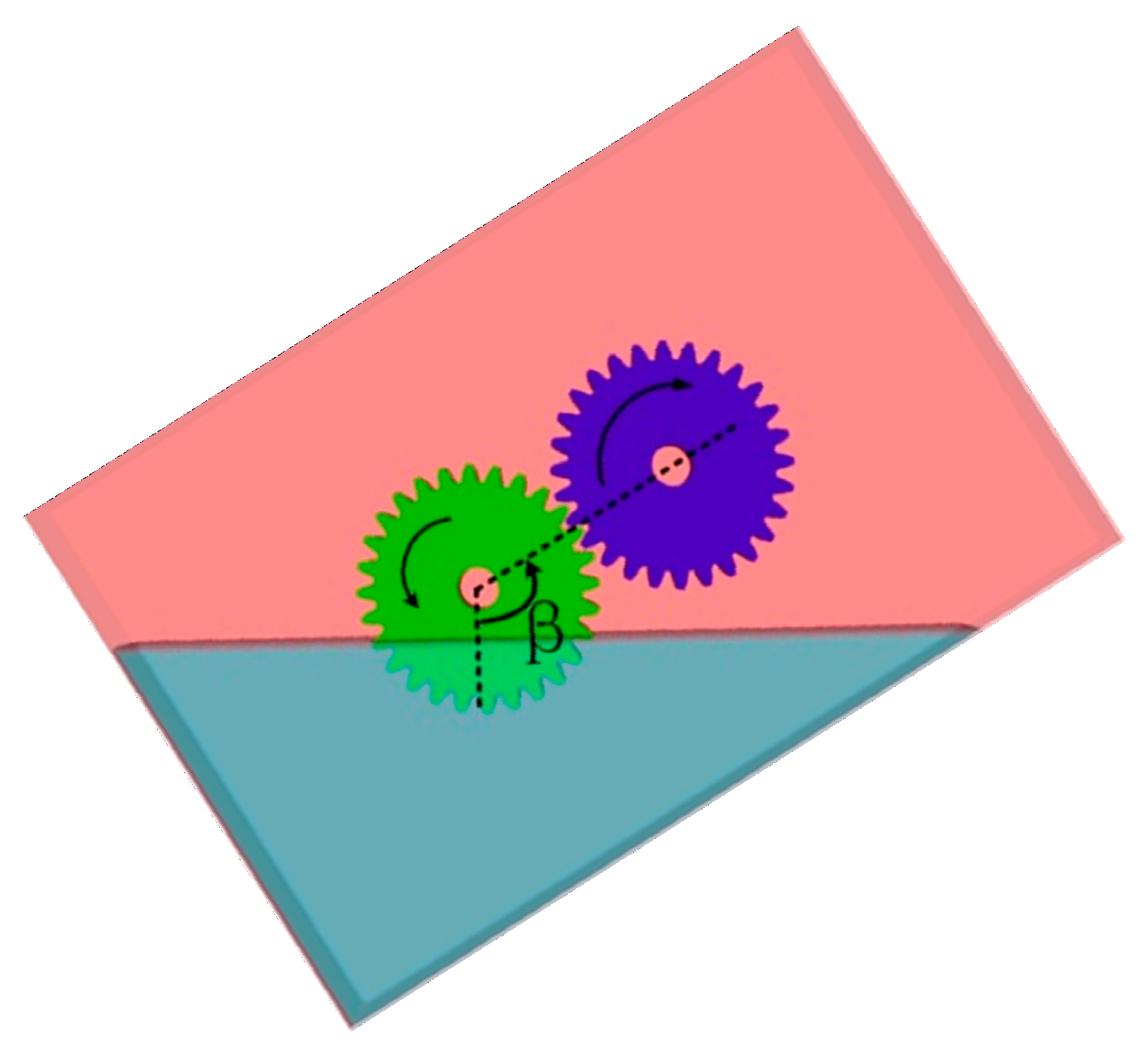
The simulation model of the gearbox was placed at different angles of inclination β, as shown in Figure 1, which means the angle for oil moved from the vertical direction to the central line of the gear pair according to the rotation direction of the gears. In the simulations, six different inclination angles 120°, 150°, 180°, 210°, 240°, and 270° were used. The initial oil surface immersion depth of the lubricating oil was 4 times the tooth depth and the temperature of oil in the tank was set as 25 °C, which is consistent with that of the experiment available in [25]; besides, for the convenience of the investigation of dynamic motion parameters of the gearbox, oil for all the simulations below was also set as 25 °C. The basic parameters of gears and lubricating oil are shown in Table 1 and Table 2.
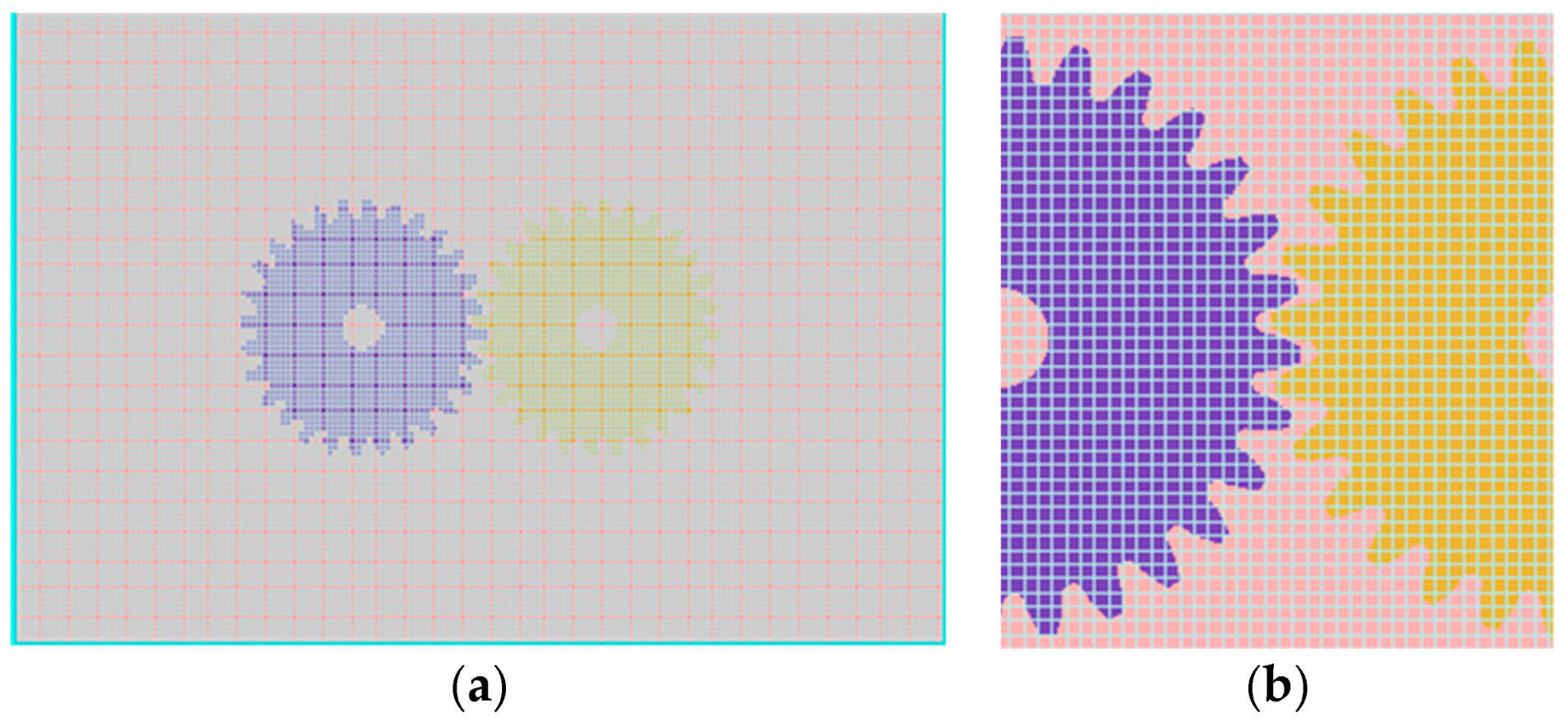
Mesh is a significant factor that can influence the precision and efficiency of simulations. In the present simulations, the grid size was 1.4 mm and the grid type was hexahedron, which can improve the calculation efficiency and maintain the calculation accuracy. The grid boundary conditions were set as symmetric boundaries. The model grid number is 602784, and the mesh details are shown in Figure 2.
The gears rotate by using the general moving objects (GMO) model [28], in which the gear was defined as a moving part with the rotation speed of 500 rpm, and the gear center was set as the rotation center. The gravity acceleration was taken into account during calculations and its value was set to 9.8 m/s2, and the viscosity and turbulence model was activated where the RNG model is chosen.
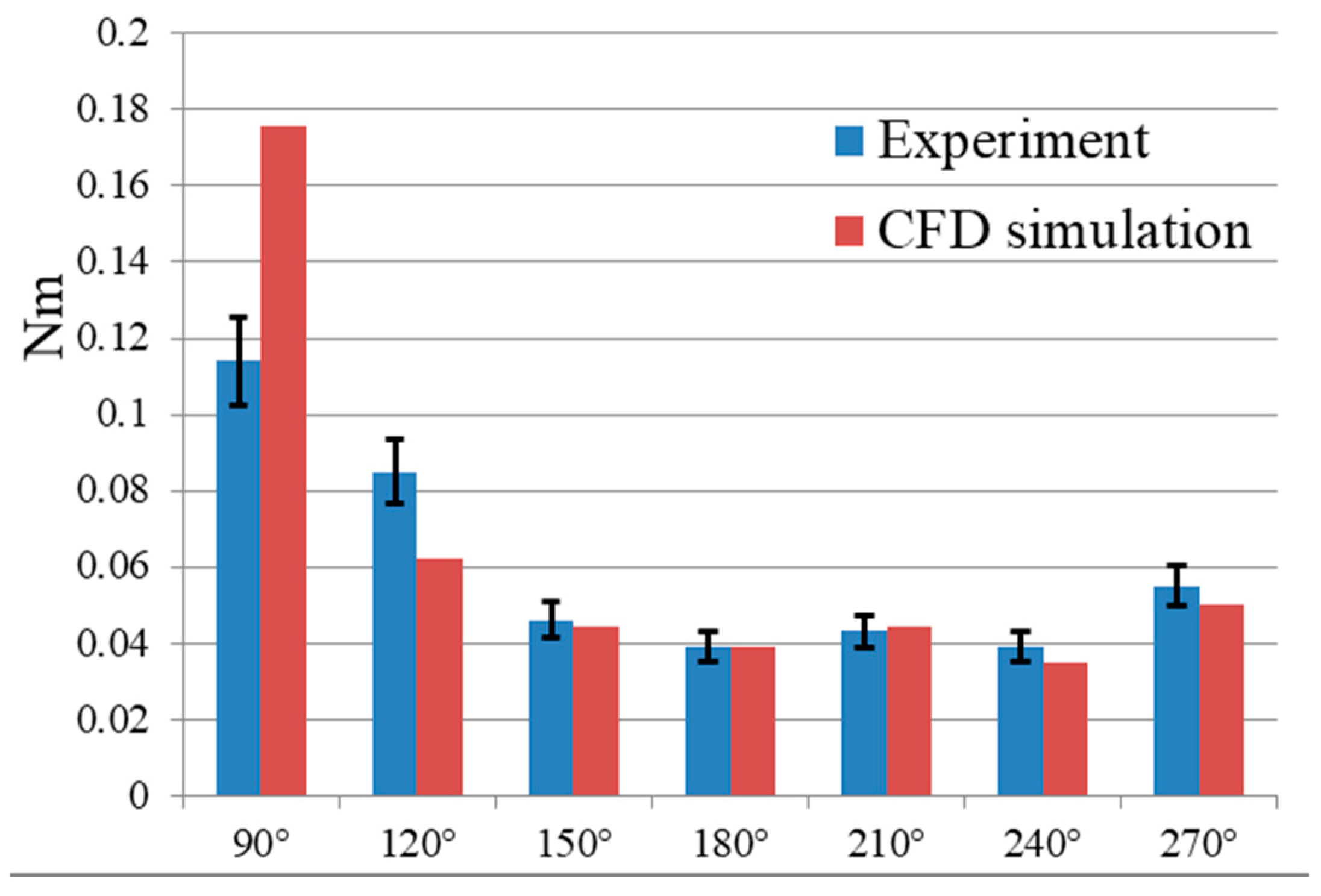
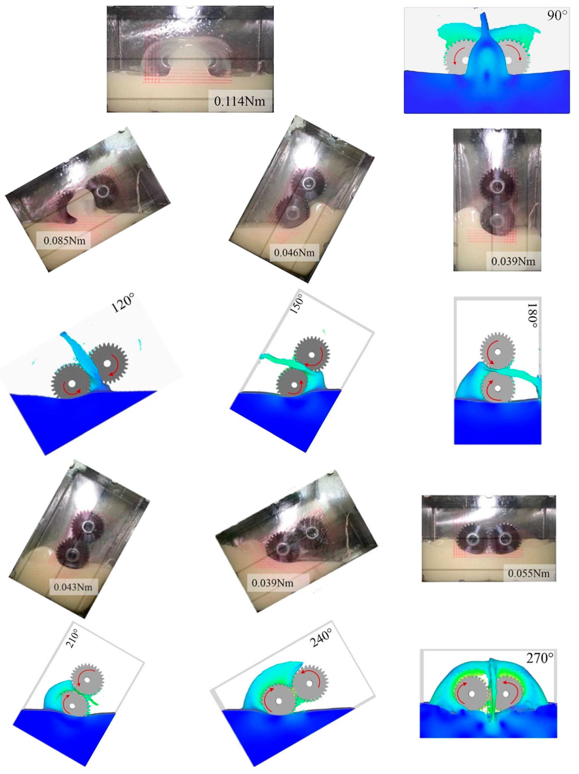
Figure 3 shows the ratios of the churning loss torque of simulations to the corresponding experimental ones, from which it can be observed that the simulation results are in good quantitative agreement with the ones obtained by experiments. Both the experimental results and the simulation data show the same trend, and data error is less than 10%, except those of 90°and 120°. As can be seen from Figure 4, the larger volume of lubricating oil concentrated in the meshing area of simulations or experiments may be the cause of the bigger data error of 90° and 120°.
Figure 4 shows the comparison of the oil free surface inside the gearbox with different inclination angles obtained by the experiments and the corresponding simulations, from which a good qualitative agreement can be observed. Also, it is worth noting that the pictures and drawings from 180° to 270° are reversed in Figure 4.
4. Simulation Results and Analysis
The above analyses indicate that the inclination angle of the initial oil surface has an important influence on the internal flow field and churning losses inside the gearbox. In most real industry cases, such as transmissions of helicopters or automobiles, gearboxes move together with these mechanical devices, therefore, it is necessary to study the effect of dynamic motion of gearboxes on flow field and churning losses.
To simultaneously simulate the motion or dynamic attitude of gearboxes and the movement of oil inside gearboxes, the non-inertial reference frame method was employed; this method inserts the computational mesh in a non-inertial reference frame, which moves with the moving gearboxes and applies fictitious forces to fluid for considering the non-inertial effects.
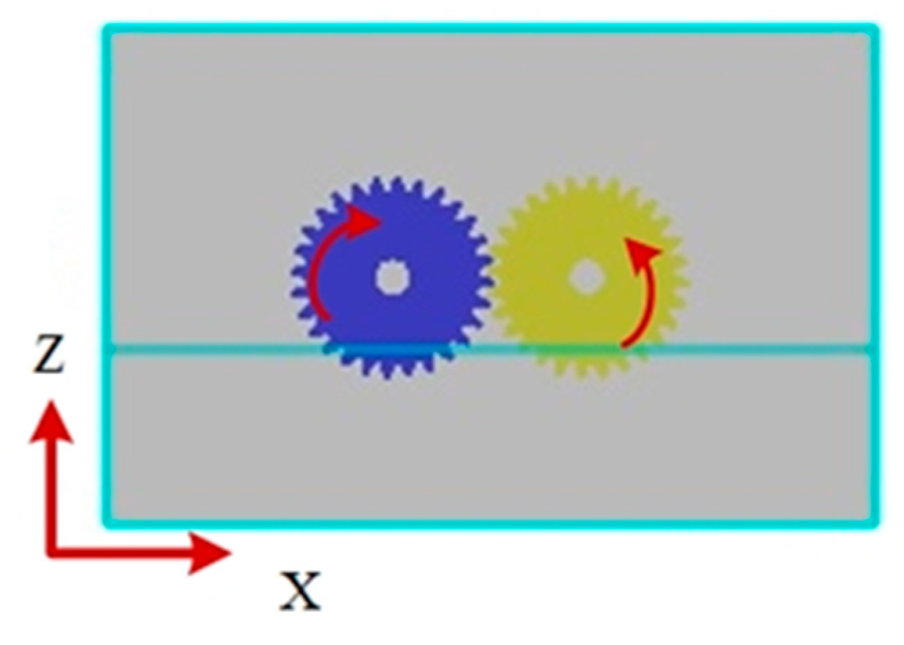
As shown in Figure 5, supposing that a gearbox moves towards the negative x-axis direction sinusoidally, its acceleration can be given by
where is the angular frequency (rad/s), d is the magnitude and ϕ is the phase angle (rad).
To investigate the effect of gear speed n, oil immersion depth H, magnitude d and frequency f of the sinusoidal motion on churning power losses inside the moving gearbox, five different rotational speeds, four different oil immersion depths, two frequencies and magnitude of the sinusoidal motion of the gearboxes were employed to form eighteen parameter combinations, which are shown in Table 3. It is noted that the parameter combination No. 0 is also called “static simulation” below. In addition, for real industrial applications, the magnitude 60 cm may be too large a value because it would cause the maximum acceleration to reach 0.6 g (gravity acceleration), which is more valid for aircraft than for automotive applications, however, to clearly observe the influence of the dynamic motion of the gearbox on churning power losses, the magnitude 60 cm was used.
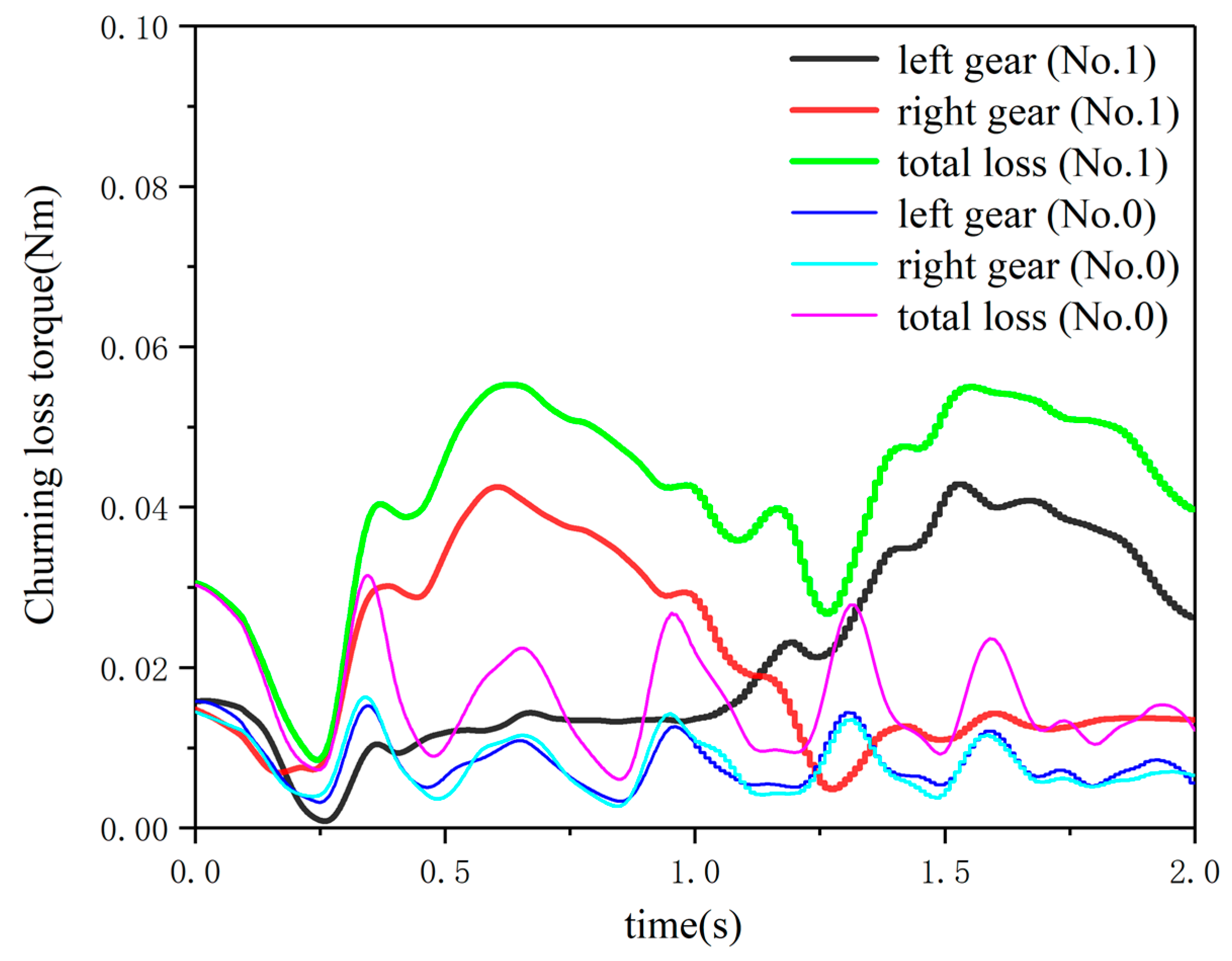
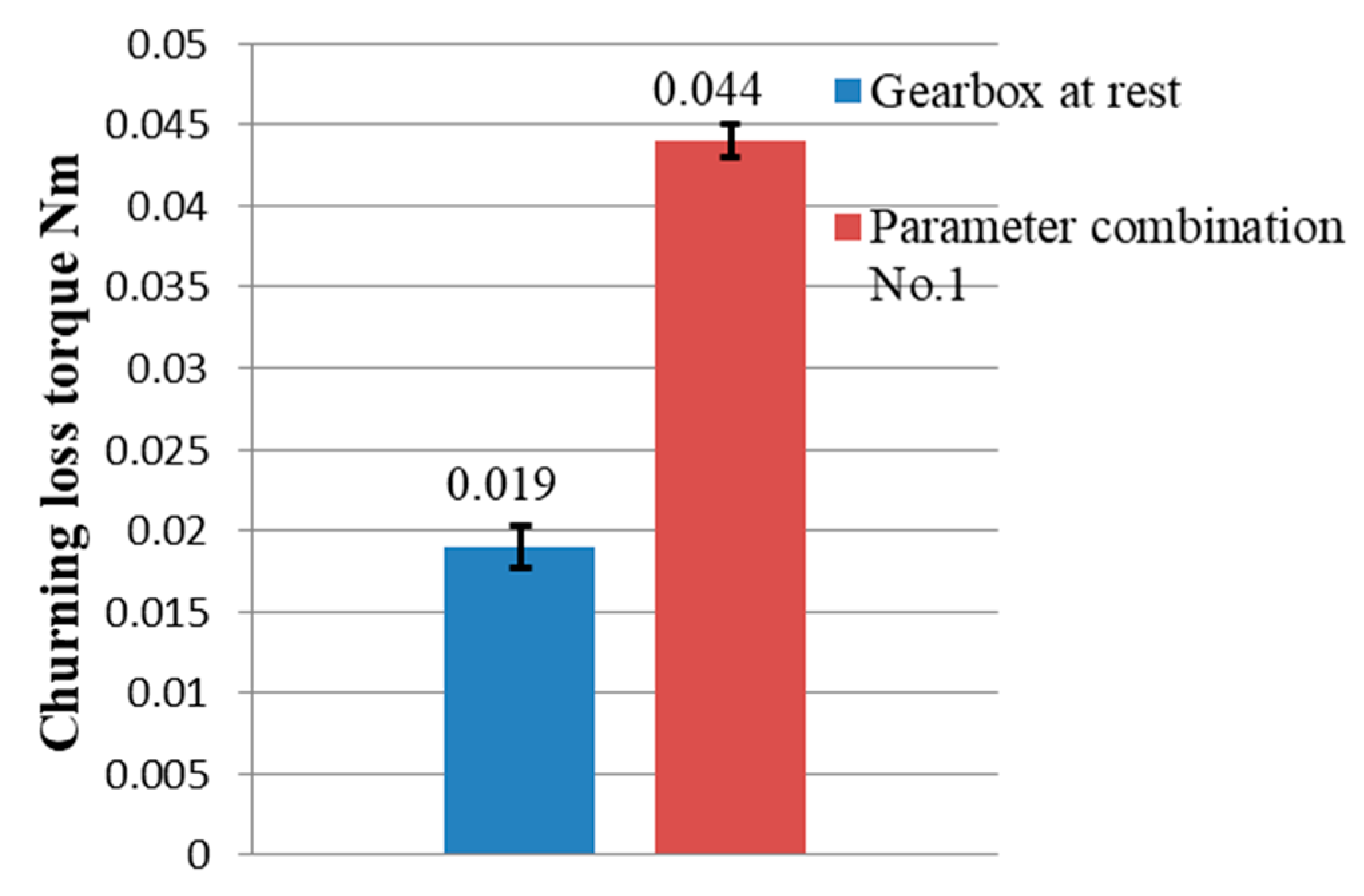
A comparison was made between the churning power losses of gearboxes with and without motion of gearboxes to reveal the influence mechanism. Figure 6 shows the churning loss torque of the gearbox with parameter combination No. 0 and No. 1, and it indicates that the internal lubricating oil sloshing caused by the motion of the gearbox has a significant influence on the churning losses. Because of the sinusoidal motion of the gearbox, the oil free surface inside the gearbox dynamic changes at all times, which causes the oil immersion depth to change correspondingly. Previous researchers have pointed out that an increase in the oil immersion depth would result in an increase in churning losses [3,5,14,28]. Figure 6 also reveals that the overall trend in the curves of the churning loss torque fluctuates greatly with the motion of the gearboxes, and the fluctuation amplitude is much larger than that at rest. Moreover, as shown in Figure 7, the average value of the churning power torque of the former is much larger than the latter, which indicates that the dynamic motion of the gearbox can exert a significant influence on churning power losses.
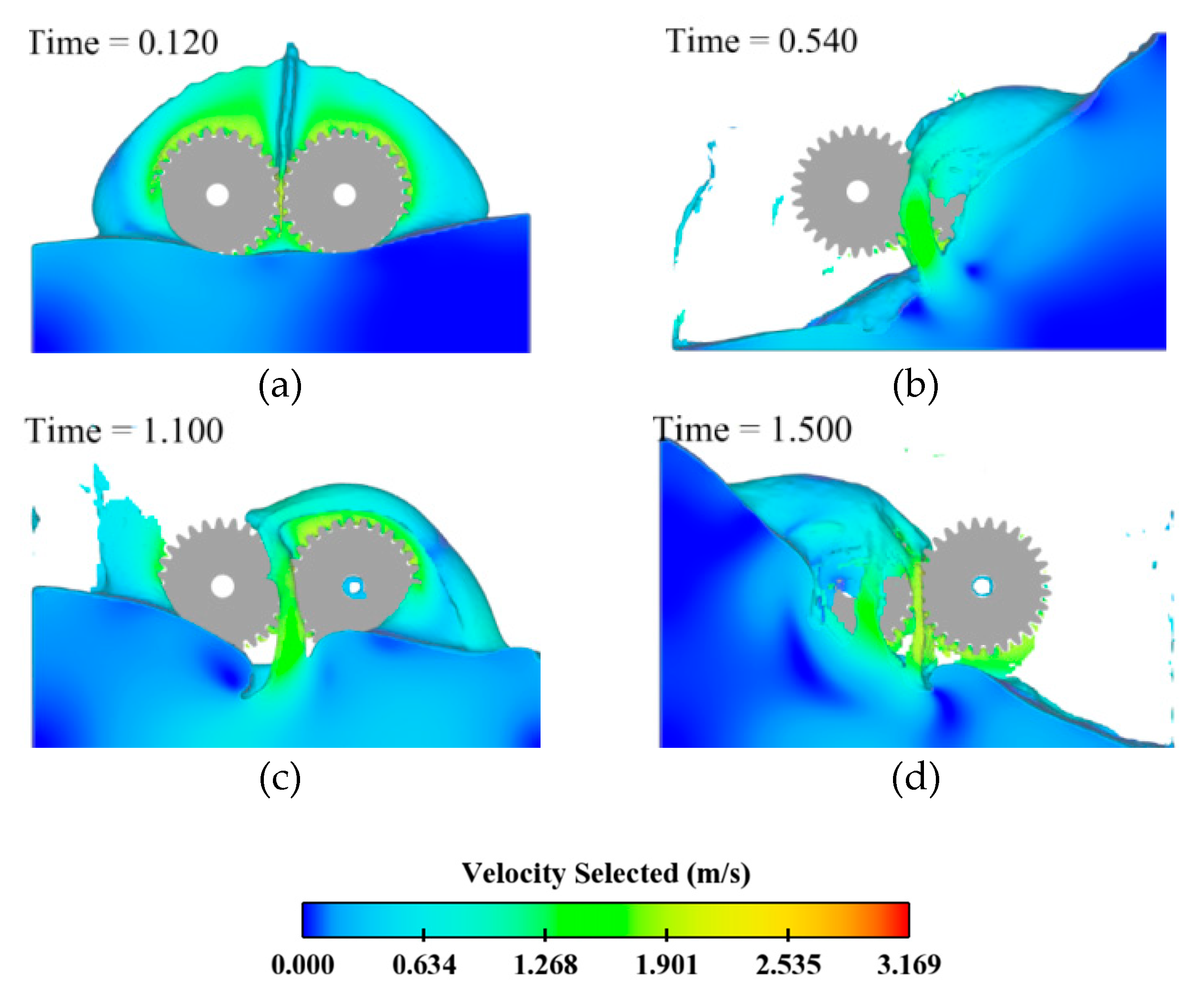
Figure 8 shows the oil free surface and velocity distribution of the flow field inside the gearbox at four time points. At the initial point, the oil level is in the horizontal position (the inclination angle β of the gearbox is 270°). At time = 0.54 s, with the moving of the gearbox, oil moves towards the right housing wall of the gearbox, which causes the oil immersion depth of the left gear to decrease significantly while that of the right gear increases, it even becomes fully immersed; therefore, at this moment, the churning loss torque of the left gear is smaller than that of the right gear. At time = 1.5 s, the reverse phenomenon can be observed.
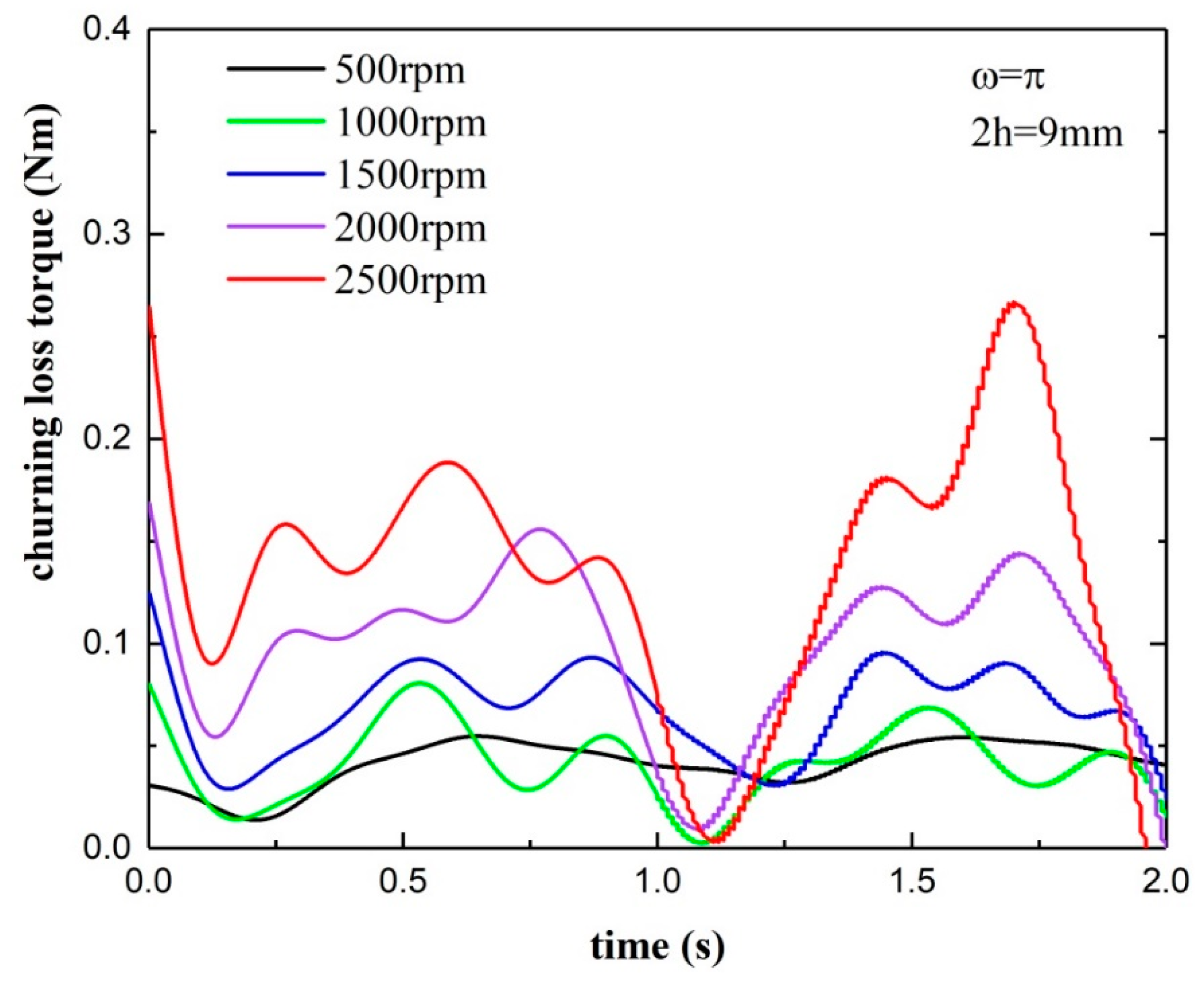
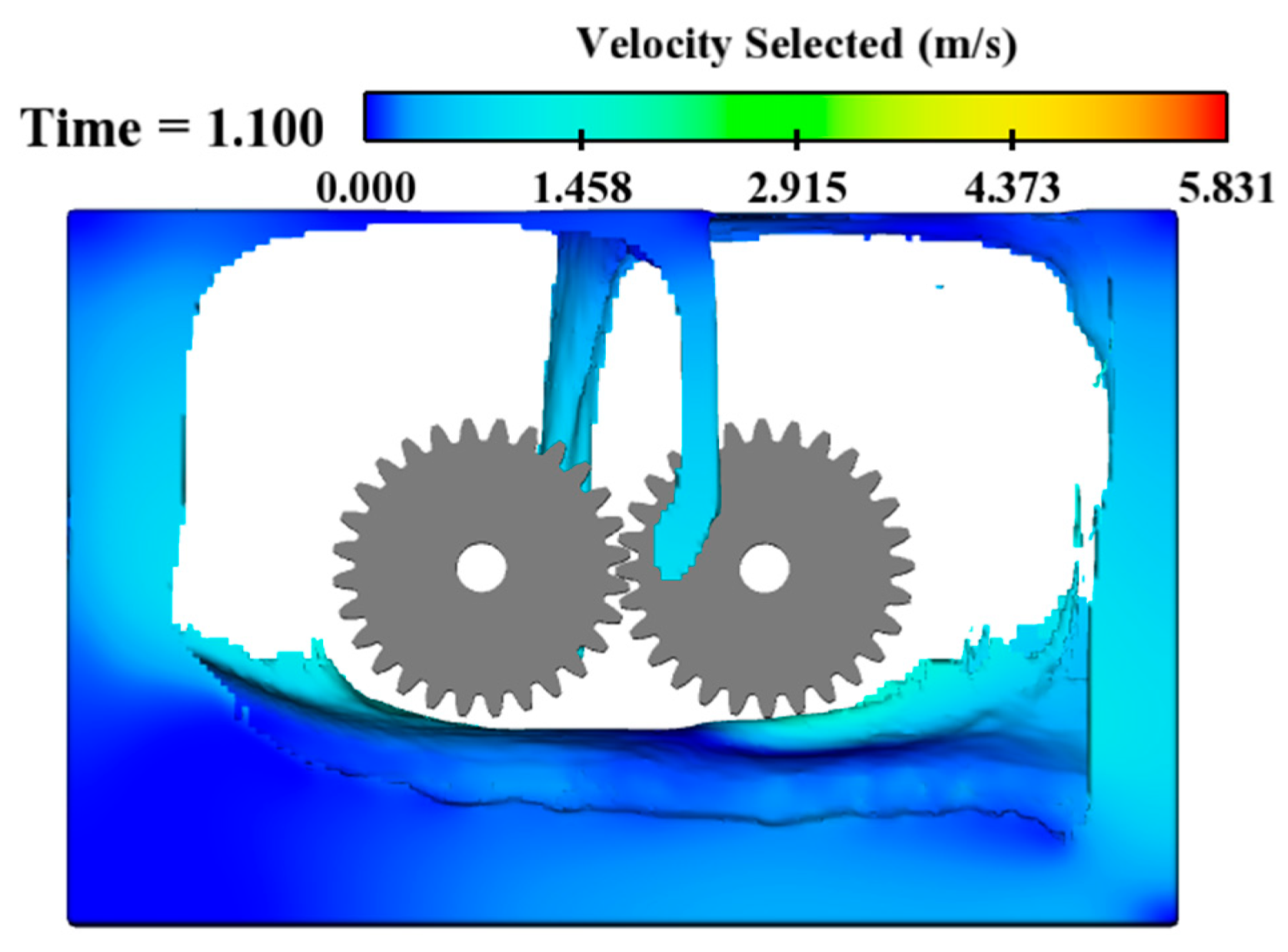
Figure 9 and Figure 10 show the time history curves and average values of churning power torques with five parameter combinations, No. 1, 2, 3, 4, and 5, of which only the rotational speeds are different. As can been seen in Figure 8, the curves of the churning power torque show a trend of fluctuations, and the curve fluctuation becomes more severe as the gear speed increases. It is noted that there is an obvious minimum value at about 1.1 s–1.25 s; this phenomenon can be interpreted in terms of the internal flow field inside the gearbox. Taking the case with a rotational speed of 1000 rpm as an example, as shown in Figure 11, it can be seen that both gears are in an un-immersed state with little oil lubrication when the time is about 1.1 s, and the lubricating oil is concentrated at the bottom and side walls of the gearbox. If the gears are in a loss-of-lubrication operating condition for a long time, their heat dissipation performance would deteriorate, and thus result in a dramatic increase in tooth temperature, even scuffing failure.
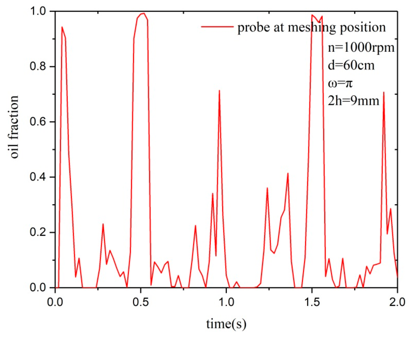
To quantitively indicate the starved-oil degree, a probe was placed at the gear meshing zone to monitor the oil fraction. Figure 12 shows that the oil fraction at the probe does not exceed 40% for most of the time, and there is no lubricating oil in the meshing zone at some moments, which is unfavorable to the lubrication of the gears. Combined with Figure 11, it can be inferred that when churning losses are approximate to zero, gears are almost in a loss-of-lubrication operating condition with no lubricating oil in the meshing zone.
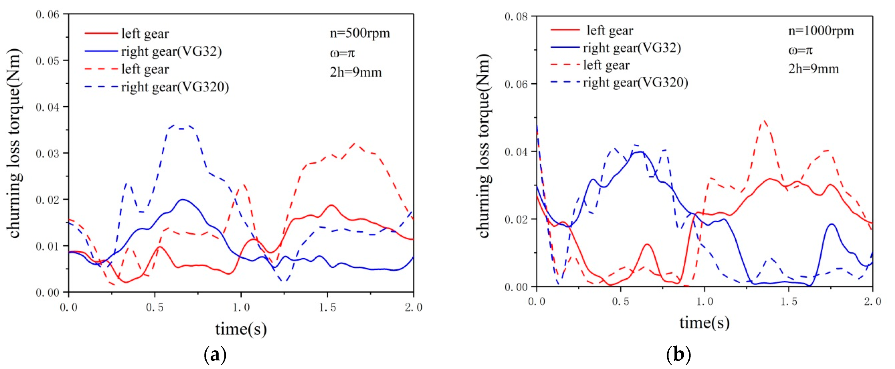
To study the effect of the oil viscosity on churning power losses, a different lubricating oil (VG32), the viscosity of which is a much lower than that of lubricating oil VG320, was used for working condition No. 14 and No. 15. The basic parameters of the lubricating oil are shown in Table 4. Figure 13 reveals the churning loss torque and the oil fraction in the meshing zone with lubricating oil VG32 and VG320. From Figure 13a,b, it can be seen that the churning power losses with VG320 are more significant than with VG32 at the initial moment for both cases at 500 rpm or 1000 rpm. With a rotational speed of 500 rpm, in the 2 s operation process, the churning loss torque with VG32 is obviously less than that with VG320; however, when the rotational speed is 1000 rpm, no great difference between the curves for VG32 and VG320 can be observed. Therefore, oil viscosity can affect the churning power losses at a lower speed, while it has less influence at a higher speed, and thus, the influence of rotational speed is obviously greater than that of oil viscosity.
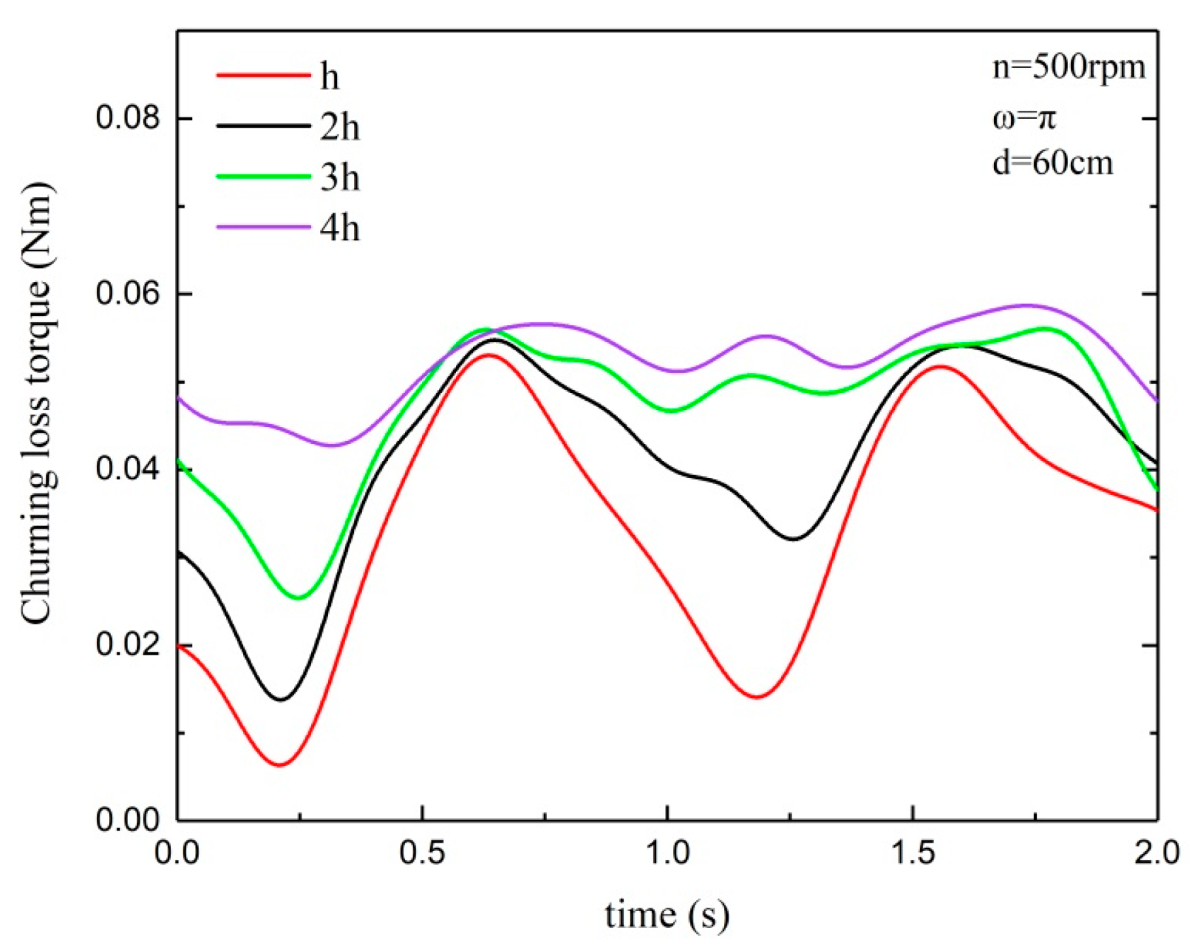
Figure 14 shows the time history curves of churning loss torques with different oil immersion depth. The overall trend is that with increasing oil immersion depth, the churning loss torque increases, while the fluctuation amplitude of its curves decreases. The greatest fluctuation occurs when the oil immersion depth is h, and the fluctuation is gentle when the oil immersion depth is 4h, which indicates that gearboxes with a low oil immersion depth are more susceptible to their own motion.
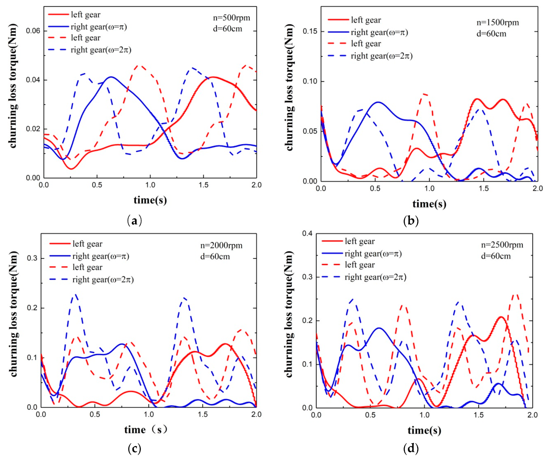
To study the effect of the frequency of the sinusoidal motion of the gearbox on churning power losses, simulations of gears at four different rotational speeds with two different frequencies were carried out, the results of which are shown in Figure 15. On one hand, when the frequency of the sinusoidal motion of the gearbox increases from π to 2π, the number of peaks of the curves of churning loss torques also increases correspondingly. On the other hand, as the rotational speed of the gears increases, the peaks of curves with a frequency 2π are larger than those with a frequency π, and at higher rotational speeds, peaks of the churning loss curves of the two gears occur simultaneously. It is worth noting that the increase in frequency reduces the time interval in which the gears are in a loss-of-lubrication state.
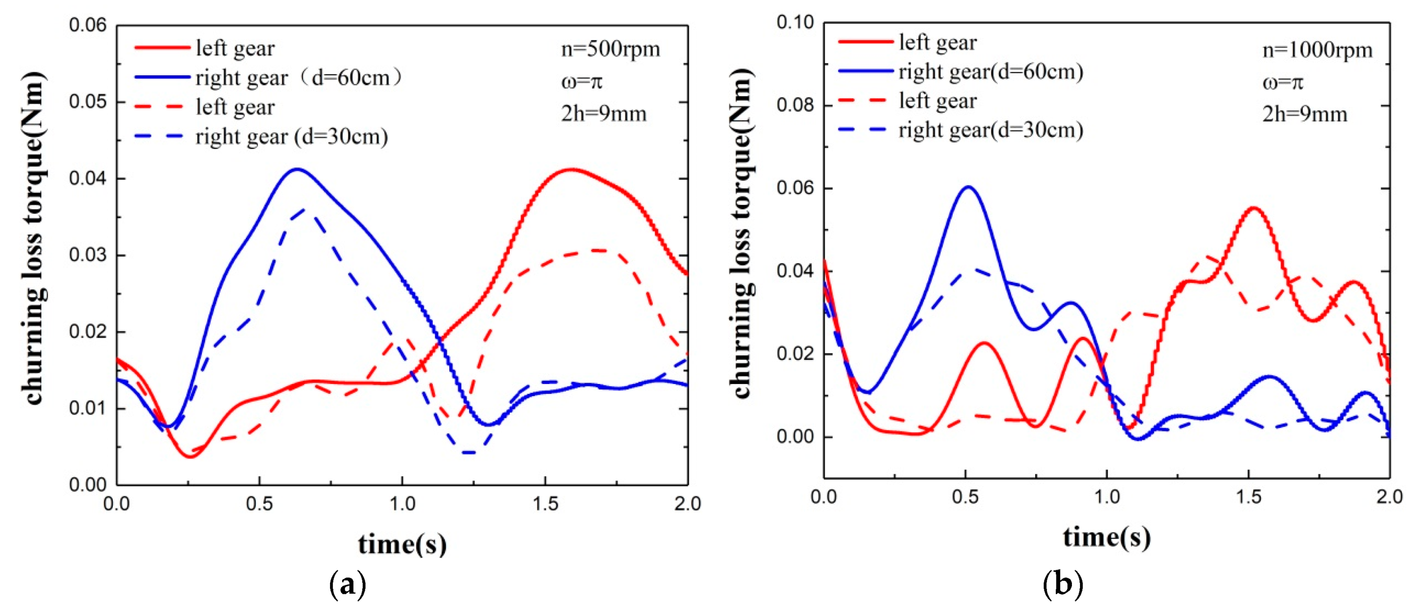
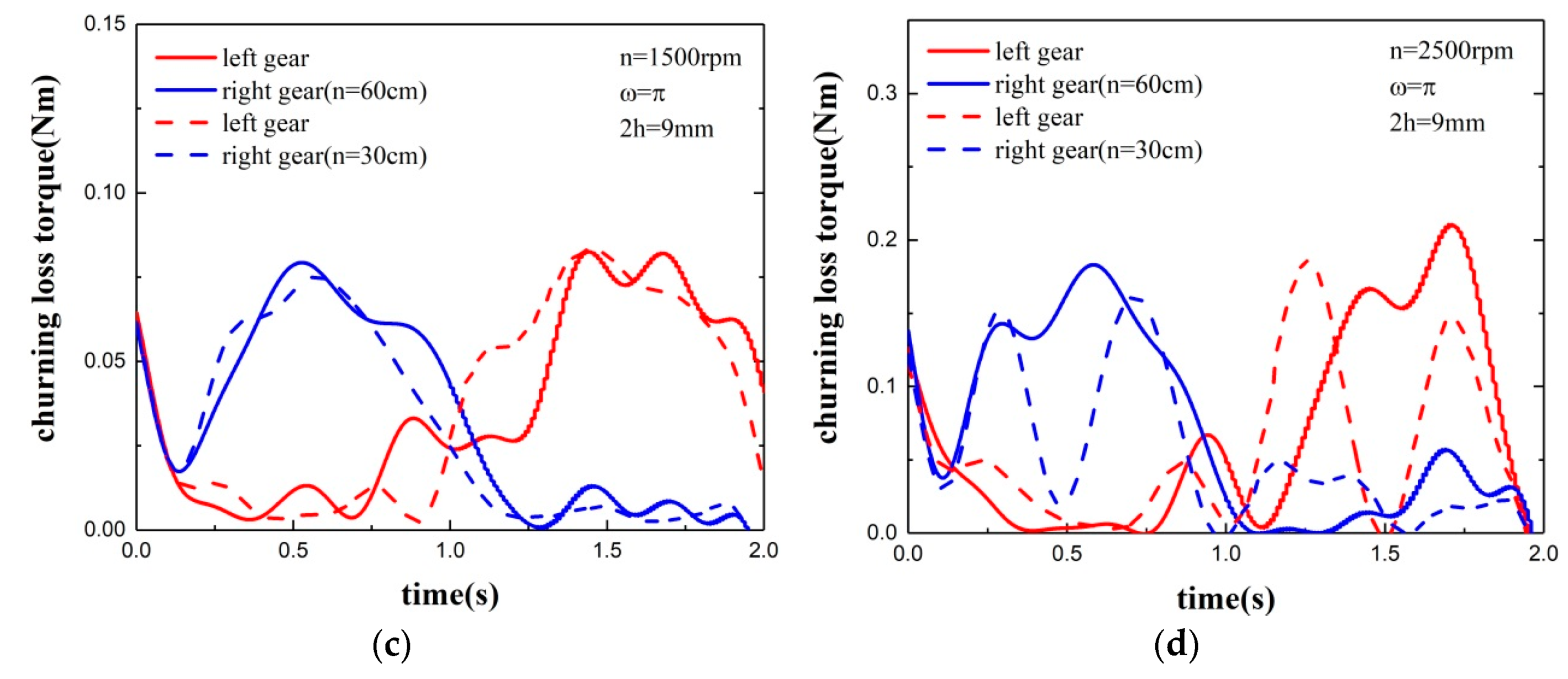
Figure 16 shows the churning loss torque of gears with different magnitudes of the sinusoidal motion of gears at four different speeds. The churning loss torque curves of gears inside the gearbox with different motion magnitudes have a similar shape and trend. Specifically, the value of the churning loss torque with a motion magnitude of 30 cm is slightly smaller than that with 60 cm; the peaks of curves occur at the same time, and the peak value of the churning loss torque decreases with the decrease of magnitude.
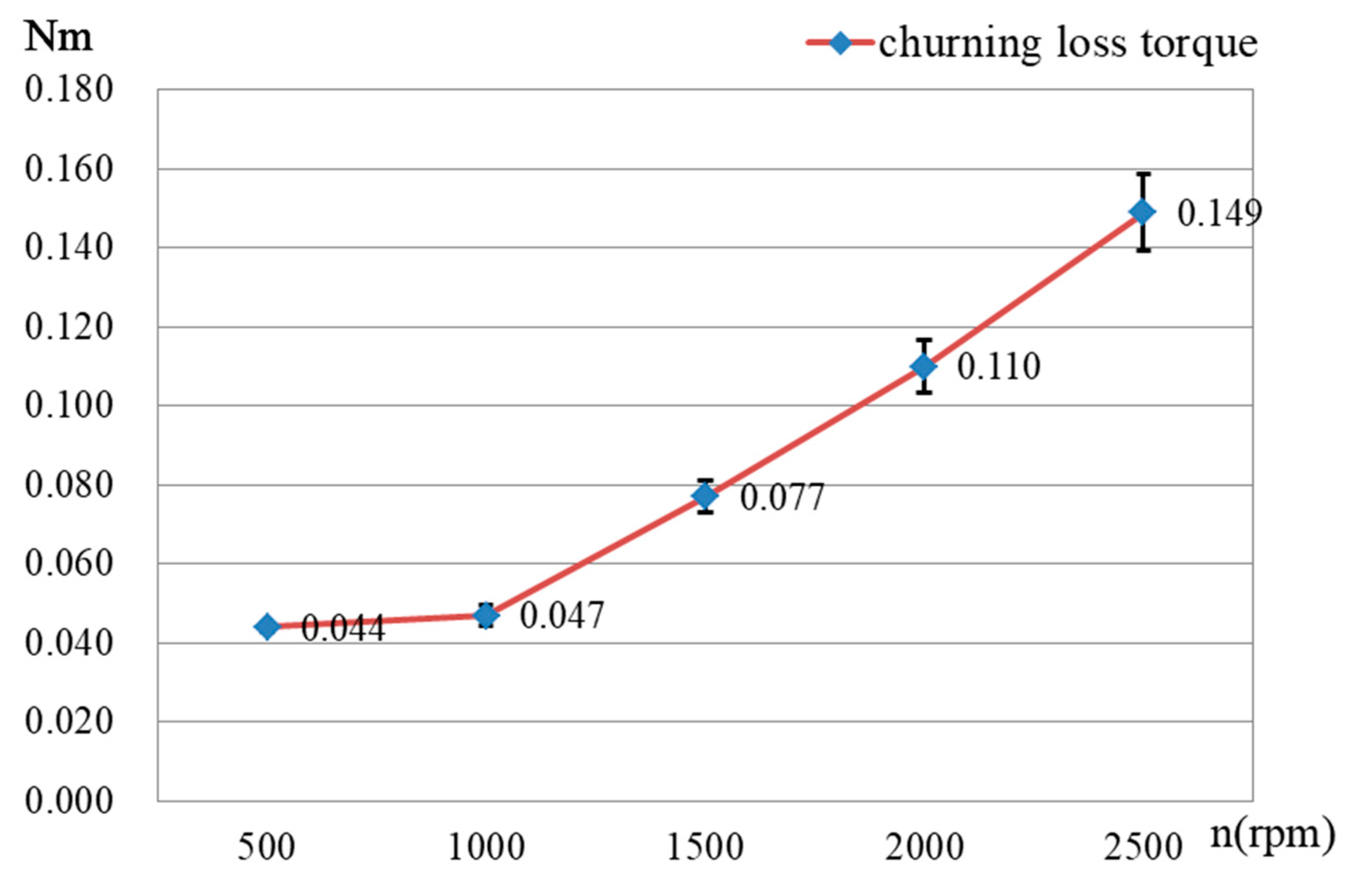
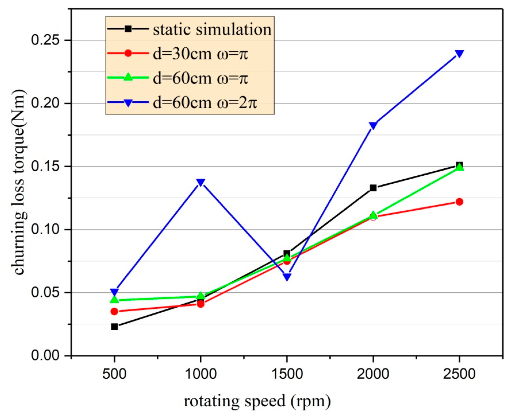
Figure 17 shows the churning loss torque value under different simulation conditions. An obvious upward trend of churning loss torque can be observed with the increase in the rotational speed of gears. When the frequency is π, the churning loss torque slightly decreases as the magnitude of the sinusoidal motion increases, and is close to that of static simulation. However, when the frequency is 2π, the churning loss torque significantly increases compared with other conditions at the same rotational speed. Therefore, Figure 17 also reveals that the frequency of the sinusoidal motion of the gearbox and rotational speed of gears have a great influence on churning losses, while the magnitude of the sinusoidal motion of the gearbox and oil immersion depth of gears have less influence.
5. Conclusions
In this study, a FAVOR method combined with an on-inertial coordinate system were applied to CFD simulations to calculate churning losses inside a gearbox with sinusoidal motion. The feasibility and accuracy of the present numerical method was verified by available test results. The effects of oil immersion depth, rotational speed, the frequency and magnitude of the sinusoidal motion of the gearbox were investigated, and the following conclusions are drawn:
(1) The sinusoidal motion of the gearbox causes the lubricating oil to oscillate, and the curves of the churning losses of the gears fluctuates with the fluctuation of the lubricating oil. When the lubricating oil tilts to the right side, the churning loss torque of the right gear is larger than that of the left gear loss, and vice versa. Due to the sloshing of lubricating oil, the gear pair may briefly be in a loss-of-lubrication state.
(2) The churning loss torque increases as the rotational speed of the gears increases, and the fluctuation amplitude increases as well. The churning loss torque increases as the oil immersion depth increases, while the fluctuation becomes gentle as the immersion depth increases.
(3) An increase in frequency reduces the time interval during which gears are in an un-immersed state, and the peak value of the churning loss torque and the number of the peak value increases. The peak value of churning loss torque decreases slightly when the magnitude decreases, and the peak for different magnitudes occurs at almost the same time.
Author Contributions
All authors contributed to this work. Conceptualization, X.H.; Methodology, P.L. and X.H.; Modelling and simulations, P.L. and M.W.; Analysis and discussion, P.L. and X.H.; Writing—Original Draft Preparation, P.L. and M.W.; Writing & Editing, X.H. and M.W.
Funding
This research was funded by the National Key Research and Development Project of China grant number 2018YFB2001500.
Acknowledgments
The authors are grateful to the National Key Research and Development Project of China (Grant No. 2018YFB2001500) for financial support of the work presented in this article.
Conflicts of Interest
The authors declare that there are no conflicts of interest regarding the publication of this article.
References
- Concli, F.; Gorla, C. Numerical modeling of the power losses in geared transmissions: Windage, churning and cavitation simulations with a new integrated approach that drastically reduces the computational effort. Tribol. Int. 2016, 103, 58–68. [Google Scholar] [CrossRef]
- Michaelis, K.; Höhn, B.R.; Hinterstoißer, M. Influence factors on gearbox power loss. Ind. Lubr. Tribol. 2011, 63, 46–55. [Google Scholar] [CrossRef]
- Neurouth, A.; Changenet, C.; Ville, F.; Octrue, M. Is splash lubrication compatible with efficient gear units for high-speed applications? In Proceedings of the 2014 International Gear Conference, Lyon, France, 24–28 August 2014; pp. 1060–1068. [Google Scholar]
- Seetharaman, S.; Kahraman, A.; Moorhead, M.D.; Petry-Johnson, T.T. Oil churning power losses of a gear pair: Experiments and model validation. J. Tribol. 2009, 131, 022202. [Google Scholar] [CrossRef]
- Seetharaman, S.; Kahraman, A. Load-independent spin power losses of a spur gear pair: Model formulation. J. Tribol. 2009, 131, 022201. [Google Scholar] [CrossRef]
- Changenet, C.; Velex, P. Housing influence on churning losses in geared transmissions. J. Mech. Des. N. Y. 2008, 130, 062603. [Google Scholar] [CrossRef]
- Kolekar, A.S.; Olver, A.V.; Sworski, A.E.; Lockwood, F.E. Windage and churning effects in dipped lubrication. J. Tribol. 2014, 136, 021801. [Google Scholar] [CrossRef]
- Liu, H.; Jurkschat, T.; Lohner, T.; Stahl, K. Detailed investigations on the oil flow in dip-lubricated gearboxes by the finite volume CFD Method. Lubr. 2018, 6, 47. [Google Scholar] [CrossRef]
- Jiang, Y.Y.; Hu, X.Z.; Hong, S.J.; Li, P.P.; Wu, M.G. Influences of an oil guide device on splash lubrication performance in a spiral bevel gearbox. Tribol. Int. 2019, 136, 155–164. [Google Scholar] [CrossRef]
- Terekhov, A.S. Hydraulic losses in gearboxes with oil immersion. Russ. Eng. J. 1975, 55, 7–11. [Google Scholar]
- Boness, R.J. Churning losses of discs and gears running partially submerged in oil. In Proceedings of the ASME International Power Transmission Gearing Conference, Chicago, IL, USA, 24–27 April 1989; Volume 1, pp. 355–359. [Google Scholar]
- Luke, P.; Olver, A.V. A study of churning losses in dip-lubricated spur gears. Proc. Inst. Mech. Eng. Part G J. Aerosp. Eng. 1999, 213, 337–346. [Google Scholar] [CrossRef]
- Changenet, C.; Velex, P. A model for the prediction of churning losses in geared transmissions—Preliminary results. J. Mech. Des. N. Y. 2007, 129, 128–133. [Google Scholar] [CrossRef]
- Höhn, B.R.; Michaelis, K.; Otto, H.P. Influence of immersion depth of dip lubricated gears on power loss, bulk temperature and scuffing load carrying capacity. In Proceedings of the International Conference on Mechanical Transmissions, Chongqing, China, 26–30 September 2006; Volume 1–2, pp. 837–845. [Google Scholar]
- Neurouth, A.; Changenet, C.; Ville, F.; Octrue, M.; Tinguy, E. Experimental investigations to use splash lubrication for high-speed gears. J. Tribol. 2017, 139, 061104. [Google Scholar] [CrossRef]
- Polly, J.; Talbot, D.; Kahraman, A.; Singh, A.; Xu, H. An Experimental Investigation of Churning Power Losses of a Gearbox. J. Tribol. 2018, 140, 031102. [Google Scholar] [CrossRef]
- Gorla, C.; Concli, F.; Stahl, K.; Höhn, B.R.; Michaelis, K.; Schultheiss, H.; Stemplinger, J.P. Hydraulic losses of a gearbox: CFD analysis and experiments. Tribol. Int. 2013, 66, 337–344. [Google Scholar] [CrossRef]
- Concli, F.; Della, T.A.; Gorla, C.; Montenegro, G. A new integrated approach for the prediction of the load independent power losses of gears: Development of a mesh-handling algorithm to reduce the CFD simulation time. Adv. Tribol. 2016, 2016, 2957151. [Google Scholar] [CrossRef]
- Concli, F.; Gorla, C. CFD simulation of power losses and lubricant flow in gearboxes. In Proceedings of the American Gear Manufacturers Association Fall Technical Meeting (AGMA), Columbus, Ohio, USA, 22–24 October 2017. [Google Scholar]
- Concli, F.; Gorla, C. Numerical modeling of the churning power losses in planetary gearboxes: An innovative partitioning-based meshing methodology for the application of a computational effort reduction strategy to complex gearbox configurations. Lubr. Sci. 2017, 29, 455–474. [Google Scholar] [CrossRef]
- Liu, H.; Jurkschat, T.; Lohner, T.; Stahl, K. Determination of oil distribution and churning power losses of gearboxes by finite volume CFD method. Tribol. Int. 2017, 109, 346–354. [Google Scholar] [CrossRef]
- Liu, H.; Arfaoui, G.; Stanic, M.; Montigny, L.; Jurkschat, T.; Lohner, T.; Stahl, K. Numerical modeling of oil distribution and churning gear power losses of gearboxes by smoothed particle hydrodynamics. Proc. Inst. Mech. Eng. Part J 2019, 233, 74–86. [Google Scholar] [CrossRef]
- Peng, Q.L.; Gui, L.J.; Fan, Z.J. Numerical and experimental investigation of splashing oil flow in a hypoid gearbox. Eng. Appl. Comput. Fluid Mech. 2018, 12, 324–333. [Google Scholar] [CrossRef] [Green Version]
- Lemfeld, F.; Fran, K.; Unger, J. Numerical simulations of unsteady oil flows in the gearboxes. J. Appl. Sci. Thermodyn. Fluid Mech. 2007, 1, 1–5. [Google Scholar]
- Chen, S.W.; Matsumoto, S. Influence of Relative Position of Gears and Casing Wall Shape of Gear Box on Churning Loss under Splash Lubrication Condition-Some New Ideas. Tribol. Trans. 2016, 59, 993–1004. [Google Scholar] [CrossRef]
- Hu, X.Z.; Jiang, Y.Y.; Luo, C.; Feng, L.F.; Dai, Y. Churning power losses of a gearbox with spiral bevel geared transmission. Tribol. Int. 2019, 129, 398–406. [Google Scholar] [CrossRef]
- Hirt, C.W.; Sicilian, J.M. A porosity technique for the definition of obstacles in rectangular cell meshes. In Proceedings of the 4th International Conference on Numerical Ship Hydrodynamics, Washington, DC, USA, 24–27 September 1985; pp. 1–19. [Google Scholar]
- Flow Science, Inc. Flow 3D User Manual; Version 11.2; Flow Science, Inc.: Leland, NC, USA, 2016. [Google Scholar]
- Hirt, C.W.; Nichols, B.D. Volume of fluid (VOF) method for the dynamics of free boundaries. J. Comput. Phys. 1981, 39, 201–225. [Google Scholar] [CrossRef]
Figure 1.
Schematic of the simulation model and the definition of β.

Figure 2.
Mesh. (a) Entire mesh; and (b) enlarged view of mesh around gears.

Figure 3.
Churning loss torque from experiments and simulations with different inclination angles.

Figure 4.
Comparison between numerical and experimental results for the oil free surface with different inclination angles.
Figure 4.
Comparison between numerical and experimental results for the oil free surface with different inclination angles.

Figure 5.
Model of a gearbox in sinusoidal motion.

Figure 6.
Time history curves of churning loss torques of parameter combination No. 0 and No. 1.

Figure 7.
Average churning loss torque with and without motion of the gearbox.

Figure 8.
Oil free surface and velocity distribution at different time points. (a) Time = 0.120 s; (b) Time = 0.540 s; (c) Time = 1.100 s; (d) Time = 1.500 s.
Figure 8.
Oil free surface and velocity distribution at different time points. (a) Time = 0.120 s; (b) Time = 0.540 s; (c) Time = 1.100 s; (d) Time = 1.500 s.

Figure 9.
Time history curve of churning loss torque with rotational speeds.

Figure 10.
Average churning loss torques with rotational speeds.

Figure 11.
Oil flow field and velocity distribution inside the gearbox (n = 1000 rpm).

Figure 12.
Oil fraction of the probe at the gear meshing zone.

Figure 13.
Influence of oil viscosity. (a) Cases with n = 500 rpm; (b) Cases with n = 1000 rpm.

Figure 14.
Churning loss torque of gears with different oil immersion depth.

Figure 15.
Influence of the frequency of the sinusoidal motion at different rotating speeds. (a) Cases with n = 500 rpm; (b) Cases with n = 1500 rpm; (c) Cases with n = 2000 rpm; (d) Cases with n = 2500 rpm.
Figure 15.
Influence of the frequency of the sinusoidal motion at different rotating speeds. (a) Cases with n = 500 rpm; (b) Cases with n = 1500 rpm; (c) Cases with n = 2000 rpm; (d) Cases with n = 2500 rpm.

Figure 16.
Influence of the magnitude of the sinusoidal motion at different rotating speeds. (a) Cases with n = 500 rpm; (b) Cases with n = 1000 rpm; (c) Cases with n = 1500 rpm; (d) Cases with n = 2500 rpm.
Figure 16.
Influence of the magnitude of the sinusoidal motion at different rotating speeds. (a) Cases with n = 500 rpm; (b) Cases with n = 1000 rpm; (c) Cases with n = 1500 rpm; (d) Cases with n = 2500 rpm.


Figure 17.
Churning loss torques under different simulation conditions.


Table 1.
Geometrical parameters of gears.
| Number of Teeth (Z) | 28 |
|---|---|
| Module (m) | 2.0 mm |
| Face width of gear (b) | 20 mm |
| Tip diameter (da) | 60 mm |
| Tooth depth (h) | 4.5 mm |
| Center distance (a) | 56 mm |
Table 2.
Physical and chemical properties of lubricating oil.
| Oil | Gear Oil ISO VG320 |
|---|---|
| Kinetic viscosity ν (40 °C) | 305.3 cst |
| Kinetic viscosity ν (100 °C) | 25.57 cst |
| Density | 0.8873 g/ |
Table 3.
Parameter combinations for simulations.
| No. | Speed, n (rpm) | Immersion Depth, H (mm) | Frequency, f | Magnitude, d (cm) | Oil Temperature (°C) | β (°) |
|---|---|---|---|---|---|---|
| 0 | 500 | 9 (2h) | 0 | 0 | 25 | 270 |
| 1 | 500 | 9 (2h) | π | 60 | 25 | 270 |
| 2 | 1000 | 9 (2h) | π | 60 | 25 | 270 |
| 3 | 1500 | 9 (2h) | π | 60 | 25 | 270 |
| 4 | 2000 | 9 (2h) | π | 60 | 25 | 270 |
| 5 | 2500 | 9 (2h) | π | 60 | 25 | 270 |
| 6 | 500 | 4.5 (h) | π | 60 | 25 | 270 |
| 7 | 500 | 13.5 (3h) | π | 60 | 25 | 270 |
| 8 | 500 | 18 (4h) | π | 60 | 25 | 270 |
| 9 | 500 | 9 (2h) | 2π | 60 | 25 | 270 |
| 10 | 1000 | 9 (2h) | 2π | 60 | 25 | 270 |
| 11 | 1500 | 9 (2h) | 2π | 60 | 25 | 270 |
| 12 | 2000 | 9 (2h) | 2π | 60 | 25 | 270 |
| 13 | 2500 | 9 (2h) | 2π | 60 | 25 | 270 |
| 14 | 500 | 9 (2h) | π | 30 | 25 | 270 |
| 15 | 1000 | 9 (2h) | π | 30 | 25 | 270 |
| 16 | 1500 | 9 (2h) | π | 30 | 25 | 270 |
| 17 | 2000 | 9 (2h) | π | 30 | 25 | 270 |
| 18 | 2500 | 9 (2h) | π | 30 | 25 | 270 |
Table 4.
Physical and chemical properties of lubricating oil VG32.
| Oil | Gear Oil ISO VG32 |
|---|---|
| Kinetic viscosity ν (40 °C) | 33.03 cst |
| Kinetic viscosity ν (100 °C) | 5.718 cst |
| Density | 0.8727 g/ |
© 2019 by the authors. Licensee MDPI, Basel, Switzerland. This article is an open access article distributed under the terms and conditions of the Creative Commons Attribution (CC BY) license (http://creativecommons.org/licenses/by/4.0/).
Share and Cite
MDPI and ACS Style
Hu, X.; Li, P.; Wu, M. Influence of the Dynamic Motion of a Splash-Lubricated Gearbox on Churning Power Losses. Energies 2019, 12, 3225. https://doi.org/10.3390/en12173225
AMA Style
Hu X, Li P, Wu M. Influence of the Dynamic Motion of a Splash-Lubricated Gearbox on Churning Power Losses. Energies. 2019; 12(17):3225. https://doi.org/10.3390/en12173225
Chicago/Turabian StyleHu, Xiaozhou, Pingping Li, and Minggui Wu. 2019. "Influence of the Dynamic Motion of a Splash-Lubricated Gearbox on Churning Power Losses" Energies 12, no. 17: 3225. https://doi.org/10.3390/en12173225
Note that from the first issue of 2016, this journal uses article numbers instead of page numbers. See further details here.