Activation of Carbon Porous Paper for Alkaline Alcoholic Fuel Cells


1
Electrochemical Thermal Energy Laboratory, Department of Mechanical Engineering, Northern Illinois University, Dekalb, IL 60115, USA
2
Department of Chemistry and Biochemistry, Northern Illinois University, Dekalb, IL 60115, USA
*
Author to whom correspondence should be addressed.
Energies 2019, 12(17), 3207; https://doi.org/10.3390/en12173207
Submission received: 28 July 2019
/
Revised: 16 August 2019
/
Accepted: 18 August 2019
/
Published: 21 August 2019
(This article belongs to the Section A: Sustainable Energy)
Abstract
:In this study, various treatment methods to increase the reactivity of carbon porous electrodes for alkaline alcoholic fuel cells were investigated with commercially available carbon papers to understand the characteristic electrochemical behaviors of the treated carbon electrodes and to find the best method to enhance the cell performance. Effects of thermal treatment, potassium hydroxide (KOH) treatment, N2 doping, and reaction-area control via a multi-layered structure were compared in the cell-based tests, and a huge improvement in the cell performance (i.e., 64% increase of open circuit voltage (OCV) and 320% increase of max power density) was found from the thermal-treated four-layered carbon porous electrode. The results were compared with those from platinum on carbon (Pt/C)-based cells, and a discussion on the direction of research in the future was conducted. The results of this study are expected to provide key guidelines for alcoholic fuel cell (AFC) developers to develop cost-effective AFC with a carbon electrode.
1. Introduction
A fuel cell is a system employed to convert the chemical energy of fuels into electrical energy without generating any emission gasses, and it is thus considered one of the most promising power sources to replace the conventional fossil fuel-based systems in order to preserve a clean and sustainable environment. In particular, alcoholic fuel cells (AFC) using easy-to-carry liquid alcoholic fuel have been considered to replace conventional batteries, especially for portable electronic devices, due to their benefits of continuous electricity generation without the need of long-time charge and the light weight of the system [1]. Intensive research on AFC has been conducted, but it has not been able to reach a full commercialization state due to the challenging issues of catalyst poisoning and reactant crossover [2,3,4].
Recently, a new AFC system based on alkaline chemistry was reported as one of the most promising systems to resolve the challenging issues of the conventional acid-type AFC [1,2,5,6]. The kinetics of electro-chemical reactions in alkaline medium is known to be very fast, which allows inexpensive but CO-tolerable materials to be used as an electrode, resolving the catalyst poisoning issue of the conventional system. In particular, the charge carrier OH− moves through the ion-exchange membrane from the cathode to anode side (i.e., opposite to the direction of the conventional acid-based AFC) of the cell during operation, and thereby prevents the alcohol crossover and flooding issue on the cathode side, which is one of the key issues of the conventional acid AFC system [1].
A high reactivity, one of the excellent benefits in alkaline AFC, has driven research to replace the expensive Pt-based catalyst needed for an oxygen reduction reaction (ORR) with inexpensive catalyst materials such as non-Pt metallic materials [2,7,8], carbon nanotube-based electrodes [9,10,11], and activated carbon porous materials [12,13,14,15,16]. Non-platinum catalysts have, in general, a poor durability and longevity due to the effect of methanol, and research has thus focused on developing catalysts that are tolerable in a methanol environment [17]. Macrocycle-based cathode catalysts such as 5,10,15,20-Tetrakis(4-methoxyphenyl)-21H,23H-porphine iron(III) chloride (FeTMPP-Cl) have been investigated because of their good activities, excellent selectivities in the catalysis of ORR, and high tolerance to methanol [18,19,20]. Transition metal oxide cathode catalysts including zirconium oxides have been studied due to their high activity and stability for the ORR [8]. Additionally, other materials such as iridium-based [7,21], palladium-based [22,23], and gold-based [24,25] cathode catalysts, have also been investigated to find inexpensive catalyst materials to replace the Pt-based catalyst.
Carbon as a non-metallic catalyst material has been studied extensively to increase its reactivity for the electrochemical reaction [9,11,12,13,14,15,16]. Nitrogen-doped carbon nanotubes (NCNTS) have been used as a cathode catalyst in AFC application due to their excellent electro-catalytic activity and stability in methanol, and the cell performance with NCNTS was comparable to that of Pt supported on carbon (Pt/C) catalysts, demonstrating the great potential of NCNTS to replace platinum-based cathodes [6,9]. Recently, a hybrid catalyst consisting of n-type nano-graphene shells (NGS), which was three-dimensionally coated on the surface of transition metal nanoparticles highly dispersed on carbon supports, was reported to efficiently facilitate oxygen adsorption owing to facile charge transfer from the metal nanoparticles, resulting in higher ORR activity from the NGS catalyst than that from a carbon-supported Pt/C catalyst [26].
The nitrogen doping method is known to introduce defects on the carbon material which facilitate the adsorption and coordination of reactive species on the active sites, and thereby improves the electro-catalytic activity [27]. The N2 doping is conducted in general through chemical vapor deposition (CVD), thermal ammonia treatment, and the pyrolysis of melamine and dopamine N2 precursors [6,9,27]. However, most of the N2 doping studies have been applied to the nano-tube structure of carbon, which needs to be prepared in special fabricating conditions, reducing the cost benefits obtained from using the inexpensive carbon.
Active research in utilizing carbon as an electrode can be found in the flow battery area. Since the first research conducted by B. Sum and M. Skyllas-Kazacos [12] on the thermal treatment as an effective method to activate graphite-felt electrodes for vanadium redox flow batteries, the thermal treatment has been extensively applied to various types of flow battery systems, including the vanadium [13,14] and hydrogen bromine system [15,16]. A significant improvement of the cell performance could be achieved due to the effect of oxygen species introduced into the carbon matrix via the thermal treatment, which facilitated the electron transfer and oxygen transfer processes. However, this activation method with conventional carbon paper has not yet been utilized for the AFC system.
Chemical treatment with strong acid or alkaline has also been investigated [28,29]. Sun and Skyllas-Kazacos modified the graphite felt with boiling concentrated sulfuric acid for 5 h, and a dramatic improvement in the electroacivity was found [29]. Alkaline chemicals such as KOH have also been used to activate carbon, and carbon fabrics have been activated by a combination of pyrolysis, KOH treatment, and thermal treatment, leading to significant enhancement of their electrical capacity [28].
The area of electrode active for the electrochemical reaction is one of the key factors in improving the cell performance, and in-depth study of the area effect on the performance has been investigated in the flow battery area. The inexpensive standard carbon paper which is commercially available was utilized to control the reaction area by stacking several sheets of papers on top of each other to make multi-layered paper electrodes. It was found that the multi-layered carbon papers consisting of three or four layers resulted in a high cell performance [13,14,15,16]. However, this method has not yet been applied to AFC.
Most of the research on carbon electrodes has focused on analyzing individual treatment methods without cross-comparing the relative effectiveness of the methods in enhancing the cell performance, and thus, it is not known which method would be the most effective in increasing the cell performance of a system of interest. In this study, four activation methods available in the literature, such as thermal treatment, the N2 doping method, chemical treatment with KOH, and reaction-area control via a multi-layered structure, will be utilized to activate the conventional carbon papers which are commercially available. First of all, the best conditions for each treatment method will be defined through cell-based performance tests. Then, the defined conditions will be applied to prepare the carbon electrode samples, and cell tests with those samples will be conducted. The results will be compared with the target performance defined from a cell with a Pt/C-coated electrode. The results of this study are expected to provide key guidelines for AFC cell developers so that they are able to develop cost-effective AFC with a carbon electrode.
2. Experimental Methods
2.1. Treatment of the Membrane
The KOH-treated cation-exchange membrane (N212, Ion Power) was utilized for this study due to the easy access to the membrane material. The membrane was treated by immersing small pieces of it 3 in × 3 in in boiling de-ionized (DI) water for 1 h and then 6 M KOH (Sigma Aldrich, PO Box 14508 St. Louis, MO 63178 USA) solution at 80 °C for 1 h. The treated membrane was rinsed several times with DI water to remove extra alkaline solution.
When KOH solution is added to the methanol fuel reservoir, hydroxyl anions (OH−) are formed in the anode fuel solution:
Then, the methanol reacts electrochemically with the hydroxide ions at the reaction sites on the anode electrode to produce water and electrons:
The generated electrons in the anode, as shown in Equation (2), pass through an external electrical circuit to reach the cathode side to take part in the electrochemical reaction with externally provided oxygen and water at the cathode electrode to generate hydroxyl anions, as illustrated in Equation (3). The negative charges of the hydroxyl anions are balanced by K+ coming from the anode side to satisfy the electro-neutral state. Therefore, K+ is a spectator ion which does not take an active part in the reaction, and also does not carry water or methanol, preventing cathode-flooding or methanol cross-over issues. The overall reaction is described in Equation (4), and the cell voltage of 1.21 V can be obtained theoretically for a standard condition.
The overall reaction is
2.2. Preparation of the Electrode
2.2.1. Preparation of the Pt/C-Coated Carbon Porous Electrode
The methanol reaction in the anode side needs a catalyst to enhance the electrochemical reaction, and a Pt-based catalyst has been utilized for most of the AFC. In this study, a Pt/C-coated carbon porous electrode (CPE) was used, and it was prepared by the following method: a proper amount of (10% Pt/C) platinum powder was measured so that 0.5 mg of Pt was coated for every 1 cm2 area of carbon paper (i.e., Sigracet 10 BC, Ion Power). The Pt/C powder was placed in a vial, and 1 µL of DI water was added for every 1 mg of platinum powder. A total of 6.67 µL of Nafion solution and 5.33 µL of pure iso-propanol were added for every 1 mg of platinum powder and the mixture was stirred by a magnetic stirrer for about 20 min to form a slurry or thick solution. The slurry was painted on the microporous layer (MPL) side of the carbon paper by a paintbrush, and was then dried at room temperature for about 24 h [30]. The prepared Pt/C-coated CPE was used as an electrode for the anode side for all the tests conducted in this study, and it was applied to both the anode and cathode sides for the test to set up the target cell performance.
2.2.2. Thermal Treatment to Activate the Carbon Porous Electrode
In order to activate the CPE via thermal treatment, 1 in × 1 in pieces of the carbon paper (Sigracet 10 AA, Ion Power) were placed in a furnace which was open to the air environment, and were heated at 300 °C, 400 °C, and 500 °C for 10 h and 20 h [12]. The treated samples were washed several times with diluted isopropyl alcohol to remove dusts or debris left inside.
2.2.3. Chemical Treatment to Activate the Carbon Porous Electrode
Pieces (1 in × 1 in) of carbon paper were submerged in 20% aqueous KOH solution at room temperature overnight, and were dried in an oven. Then, the samples were positioned in an argon quartz tube furnace (GSL-1100X, MTI, 860 S. 19th Street, Richmond, CA 94804-3809, USA), and thermally heated at temperatures from 500 °C to 800 °C for 40 min, minimizing possible effects by oxidizing impure gases [28]. Additionally, the treated samples were washed several times with diluted isopropyl alcohol, and dried before using them for the cell test.
2.2.4. Nitrogen Doping to Activate the Carbon Porous Electrode
The incorporation of nitrogen moieties into the carbon structure was conducted by pyrolyzing melamine (C3H6N6) (Sigma Aldrich), which has three triazine heterocyclic organic compounds, as a nitrogen-contained precursor. Pieces of carbon paper (1 in × 1 in) were washed several times by dilute acetone, and were then soaked in the aqueous melamine solution overnight to absorb enough melamine inside. They were dried in an oven, and were positioned in the argon quartz tube furnace (GSL-1100X, MTI) at 900 °C for 10, 20, and 30 h [27]. At this high temperature, the melamine absorbed in the porous carbon paper was split to release free nitrogen, which dopes at surfaces of carbon material.
2.3. Cell Structure and Test
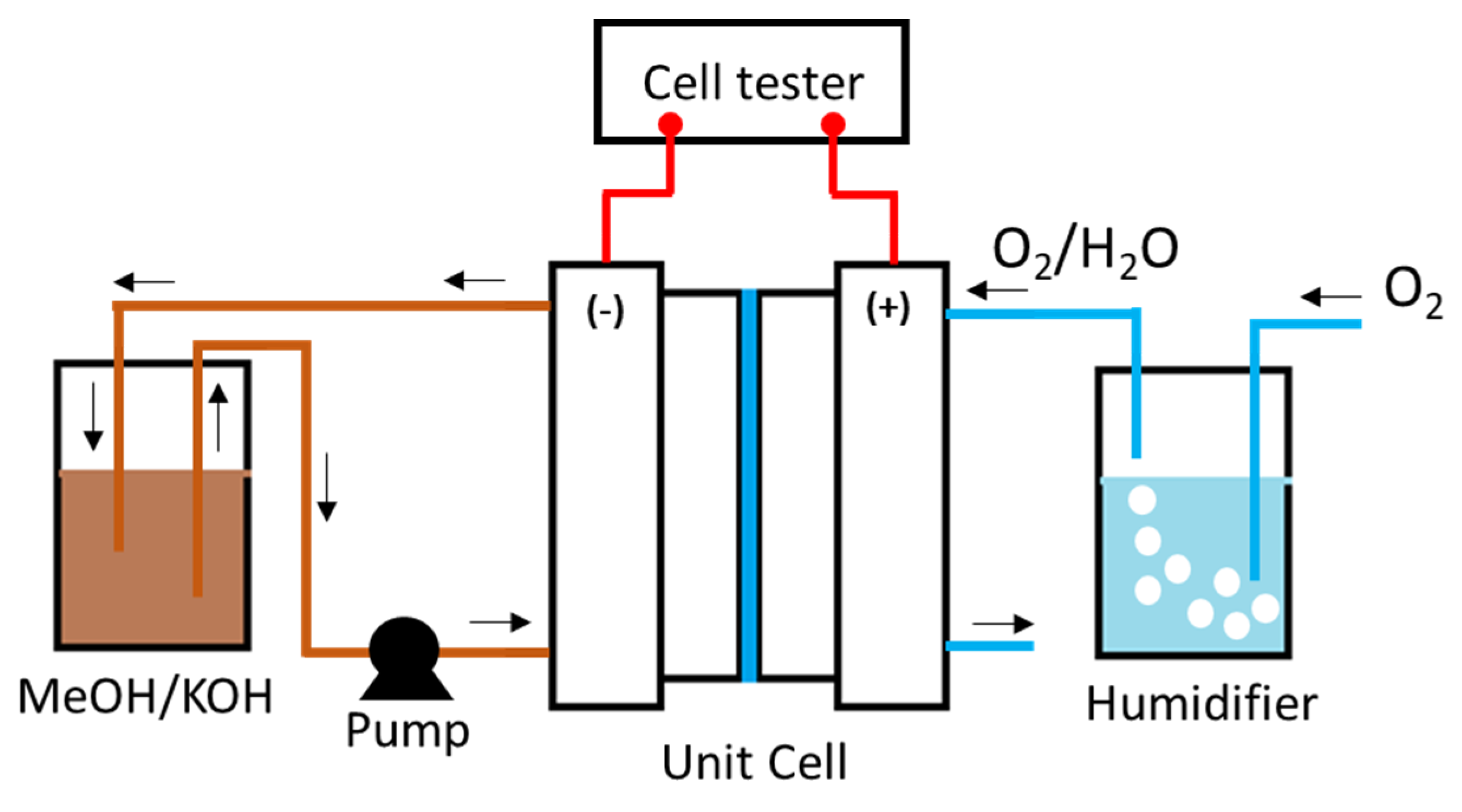
A unit cell consists of a KOH-treated membrane in the middle, Pt/C-coated CPE and serpentine flow field on the anode side, and activated CPE and the serpentine flow field on the cathode side. The cell was assembled by compressing cell components stacked in the sequence (i.e., Anode flowfield|Pt/C-coated CPE|membrane|activated CPE|cathode flow field) by eight bolts to minimize the electrical contact resistance among the components. O2 (industrial grade, Airgas, 259 No. Radnor-Chester Rd. Radnor PA, 19087-5283, USA) was humidified through a bubbler-type humidifier, and the humid O2 (i.e., gas mixture of O2 and H2O) was provided to the cell at a flow rate of 50 sccm controlled by a flow meter (McMaster Carr, 600 N County Line Rd.Elmhurst, IL 60126-2034, USA). For the anode side, an aqueous mixture of methanol and KOH (i.e., 8M methanol and 4M KOH aqueous solution) [1] was provided to the anode side of the cell at 3 mL/min via a peristaltic pump (Masterflex L/S, Cole Parmer, 625 East Bunker Court Vernon Hills, IL 60061, USA), and the exit solution from the cell flowed back to the container. The cell performance was measured in galvanostatic mode with a battery tester (Model 4304, Maccor, 4322 South 49th West Ave Tulsa, OK 74107, USA). A detailed schematic diagram of the test setup is shown in Figure 1.
3. Results and Discussion
3.1. Baseline Performance of the Carbon Electrode and Pt/C-Coated Electrode
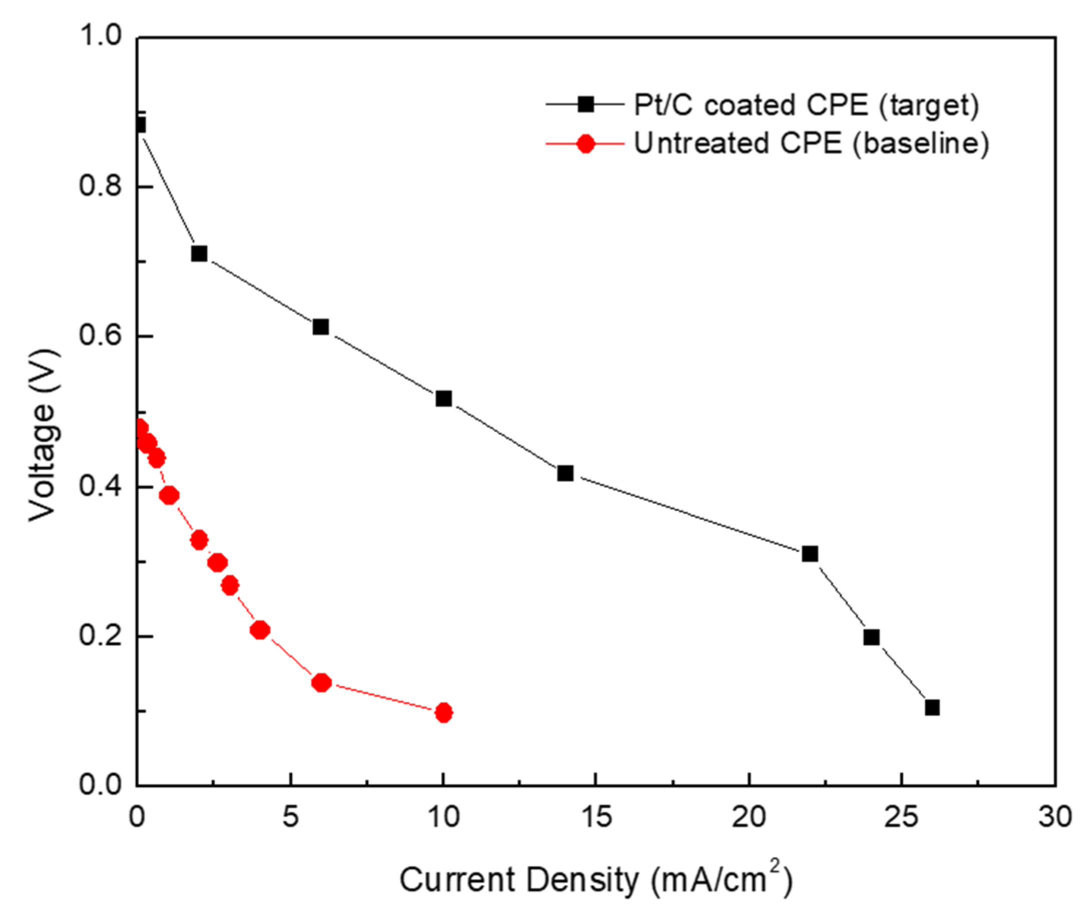
A cell performance test was conducted first, with a cell having untreated CPE as a cathode electrode, in order to have a baseline performance for carbon electrode material. Additionally, a cell with Pt/C CPE on the cathode side was tested to setup the target performance to achieve with the carbon electrode. Both the cell tests were conducted with the same operating conditions and cell structure, except for the cathode-electrode material, and the difference in the measured performance was thus the direct result of reactivity difference in the utilized electrode materials.
As shown in Figure 2, the performance of the cell with untreated CPE was significantly lower than that of the cell with Pt/C, as expected. The open circuit voltage (OCV) was around 0.5 V, which is 44% less than that of the Pt/C-cell, and the maximum current density was around 10 mA/cm2, which is 61% less than the Pt/C-cell, indicating that the carbon paper cannot be used in the AFC unless it is activated. Various methods will be applied in this study to activate carbon paper to increase the cell performance, and all the details of these treatments and results will be described in the subsequent sections.
It should be noted that the performance measured in this study may be different from what is reported in the literature due to the difference in cell components, and we will thus utilize the cell polarization behaviors plotted with respect to the current density normalized by the maximum current density to compare the relative performance for various activation methods on the same scale.
3.2. Thermal Treatment (Thermal Oxidation)
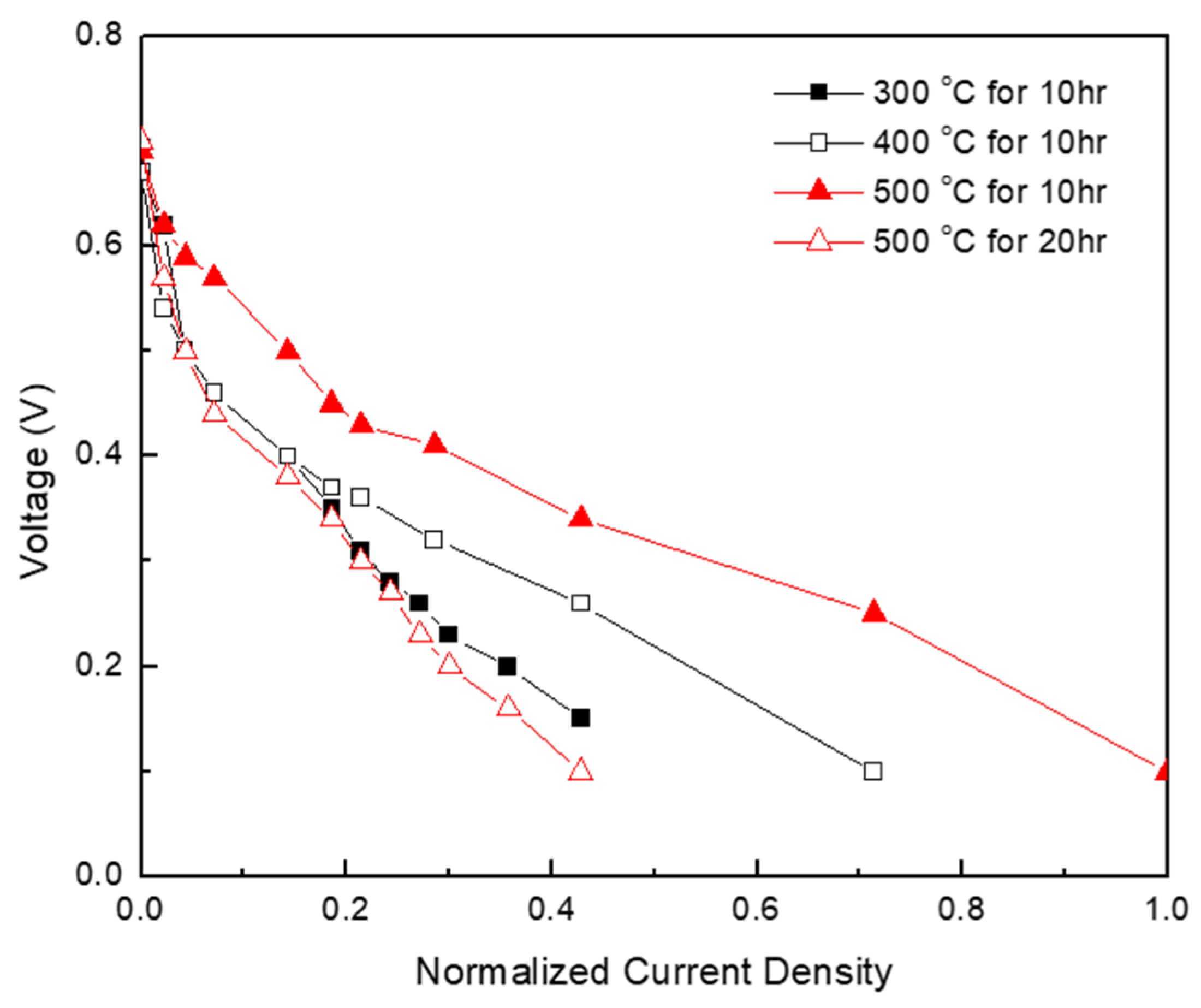
The effect of thermal treatment (or thermal oxidation) was analyzed by comparing the performances of cells consisting of the cathode CPEs, which were treated at 300 °C, 400 °C, and 500 °C for 10 h and 20 h in the air environment. For the anode side, the Pt/C-coated electrode was applied for all cell tests. The polarization behaviors were measured with respect to the current density normalized by the maximum current density to compare the relative performance clearly, as described previously.
As shown in Figure 3, especially for the cases of CPEs thermally treated at 300 °C, 400 °C, and 500 °C for 10 h, voltages at a zero current (i.e., open circuit voltage, OCV) were not so different for all the treated samples, but in the kinetic limited zone (i.e., performance at a low current density), a significant voltage drop was found from all samples except the CPE, which was treated at 500 °C for 10 h, indicating that the kinetic property for this sample was improved. Additionally, the ohmic property, which can be estimated by the slope of voltage drop vs. current in the linear region of the plot, was not so different for all the samples. However, the big difference in performance was found in the high current region, which is known as the mass transfer limited region, and the performance was improved as the treatment temperature increased, indicating that the treatment temperature directly affected the mass transfer property.
These results (i.e., improvement of kinetic and mass transfer properties) can be understood from the effect induced by thermal treatment in the air environment. The oxygen species introduced into the carbon matrix during the treatment facilitate the electrochemical reaction by increasing kinetics [12], and they also render the surface hydrophilic, allowing the aqueous-based reactants to readily access the porous electrode, and thereby mass transfer could be enhanced [14,15,16]. However, when the treatment time was increased further to 20 h, the cell performance dropped significantly, which is due to degradation of the carbon matrix caused by excessive oxidation during the treatment. This conclusion is supported by the dimension change (10%–20% thickness change) of the carbon paper treated at 500 °C for 20 h.
3.3. Chemical Treatment (KOH-Heat Treatment)
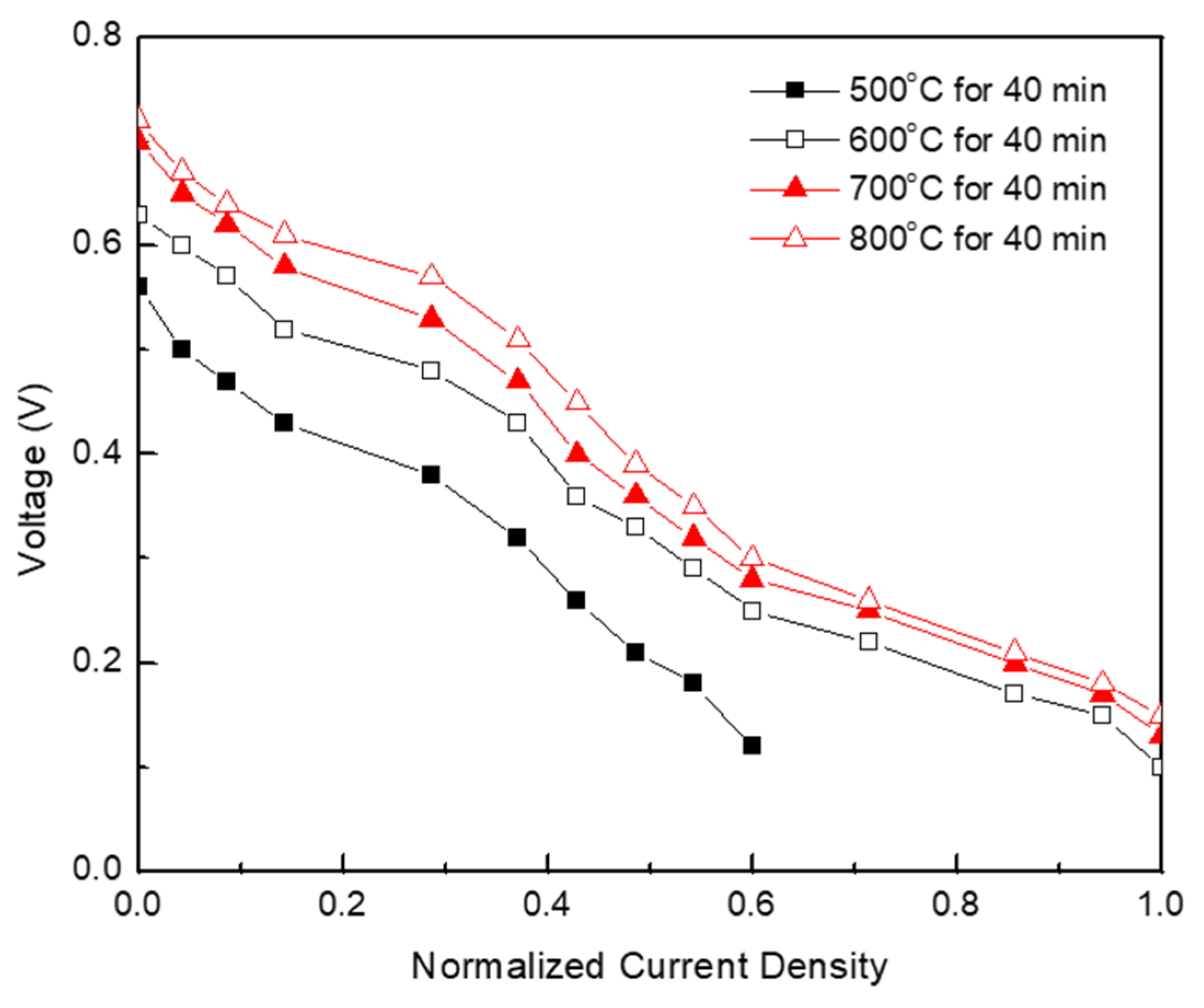
Four treated CPEs (i.e., at 500 °C, 600 °C, 700 °C, and 800 °C for 40 min in an argon environment after KOH treatment) were prepared as described in the experimental section, and the performance was measured from the cells with treated CPEs. As shown in Figure 4, for the case of 600 °C, 700 °C, and 800 °C treated CPEs, the behaviors of kinetic loss (drop in cell voltage in a low current range), ohmic loss (slope of voltage drop vs. current), and mass transfer loss (voltage drop in a high current range) are very similar in all three cases, and their graph lines are shifted on the y-axis by several voltages (0.3 to 0.5 V) from each other.
This behavior is very similar to the case of reaction-area control via a multi-layered structure, as explained in the last section of the treatment effect, and it can thus be concluded that KOH treatment mostly increases the reaction area without further changing other properties, such as kinetics, ohmic, and mass transfer in the treatment temperature range from 600 °C to 800 °C. This conclusion is supported by the literature [28,31,32], which reports that KOH activation improves the specific surface area of carbon, resulting in a significant increase of capacity for the super-capacitor application. This characteristic behavior can be further understood by considering the activation conditions when the samples were heated in an inert Ar gas environment. Therefore, the effect of oxidizing impure gases, which are known to significantly change the properties of carbon material, could be eliminated, resulting in no sensible change of other properties. It is a very interesting result, and detailed study to define the reason for this behavior is required, which represents future work. For the case of 500 °C treatment, a very low performance was found, indicating that the treatment temperature was not high enough to activate the carbon material.
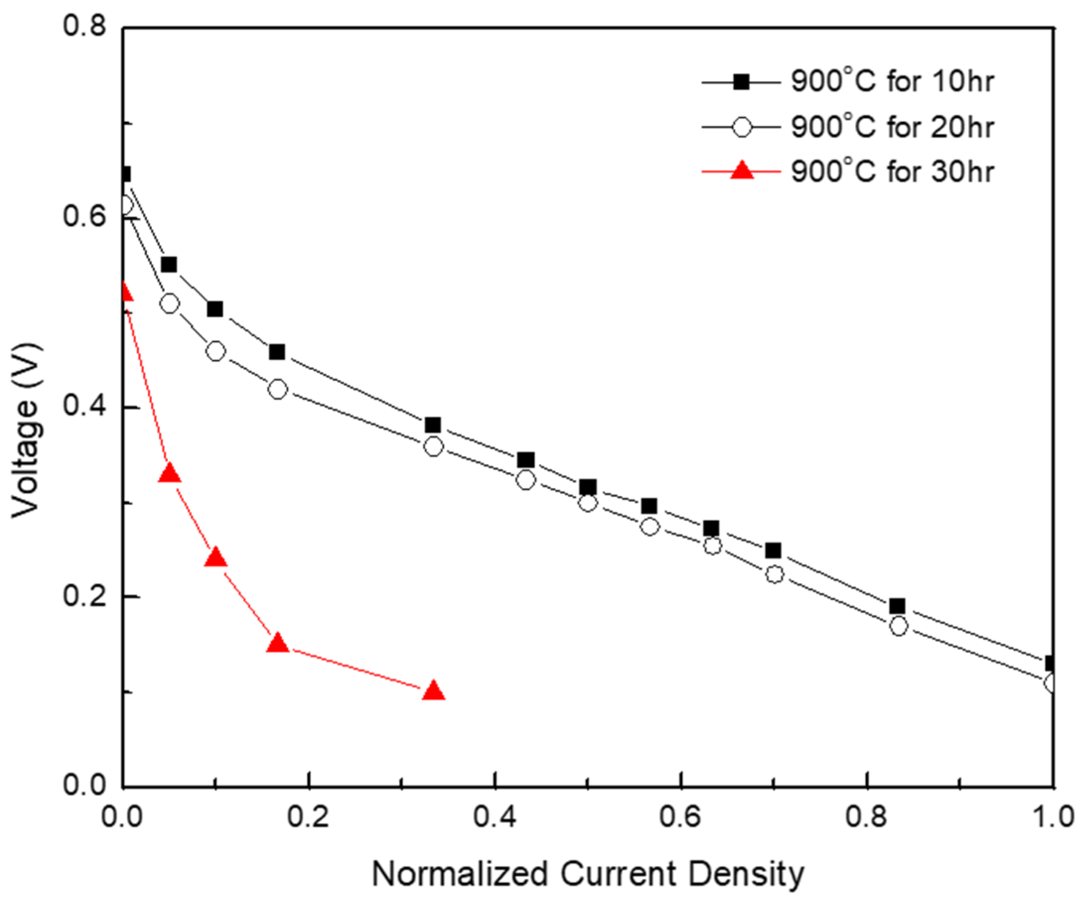
3.4. Nitrogen Doping
Nitrogen was doped on the surface of carbon porous papers at 900 °C for 10 h, 20 h, and 30 h in an argon environment. Its effect on the cell performance was compared with the polarization curve, as shown in Figure 5. As the treatment time increased from 10 h to 20 h, the overall voltage was decreased slightly by 30 mV, and as the treatment time increased further to 30 h, a significant performance drop by 90 mV was found, indicating that the carbon matrix in the carbon paper may have been degraded during the extended exposure to a high temperature.
It should be noted that this high temperature is a general condition in doping nitrogen to carbon [9,27], but in this experiment, we used carbon porous papers, which have resins and binders impregnated in their manufacturing process [33], and thus, those additives holding the matrix structure of carbon fibers together may have been degraded in this harsh condition of long exposure to a high-temperature environment, leading to a significant decrease of cell performance. This degradation of CPE can be understood by the dimensional change (10%–20% of thickness reduction) of carbon papers after the treatment at 900 °C for 30 h.
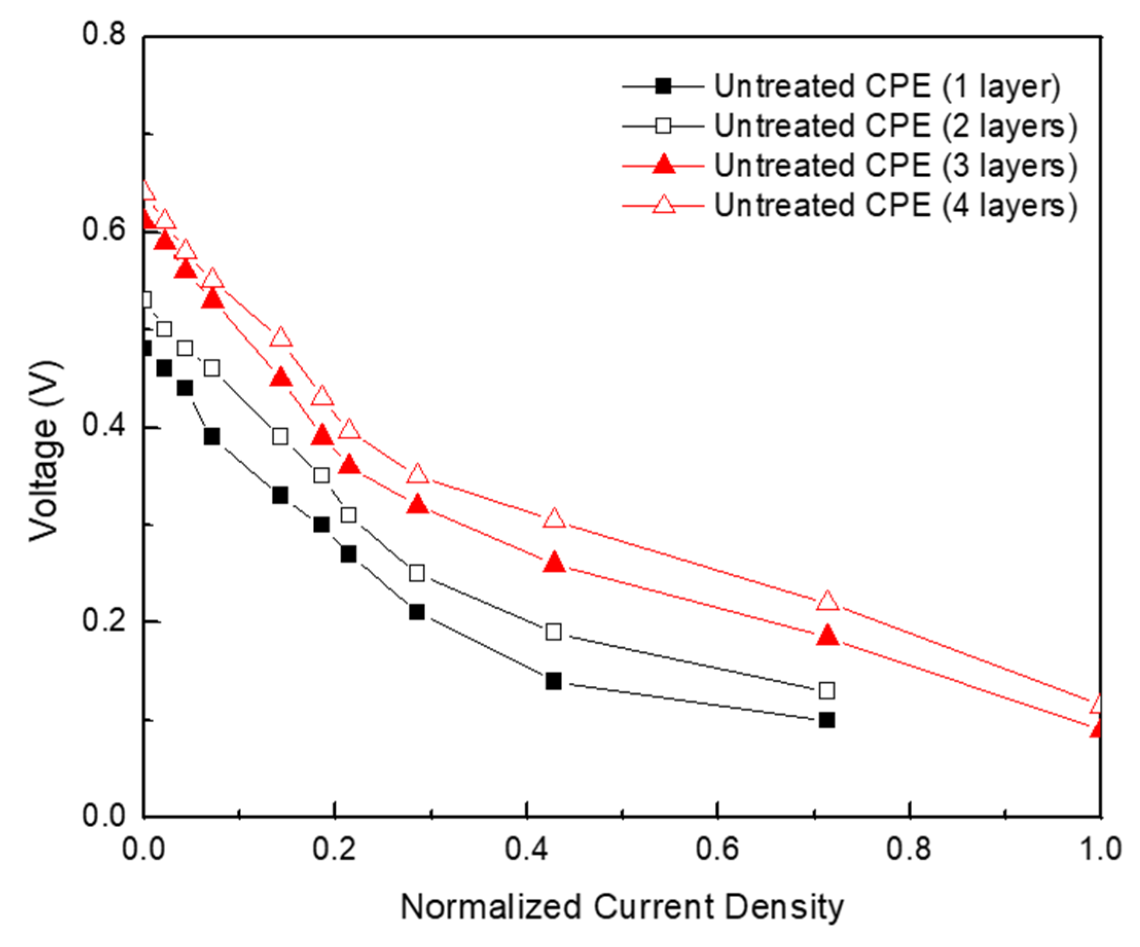
3.5. Reaction-Area Control via a Multi-Layered Structure
The inexpensive standard carbon paper which is commercially available was utilized to control the reaction area by stacking several sheets of papers on top of each other to make multi-layered paper electrodes (thickness of one layer is about 0.35 mm).
As illustrated in Figure 6, OCV was increased from 0.48 V for one layer to 0.64 V for four layers (i.e., 33% increase), but there were no big differences in the ohmic property found for the multi-layered electrodes, which seems to contradict the research results in the flow battery area [13]. However, this behavior can be understood by checking the operating current ranges. The current condition of the AFC is several orders of magnitude smaller than that of the flow battery, and thus, the effect of the ohmic drop was not significant (i.e., ). In the case of three- and four-layered electrodes, cells were able to be operated at higher current conditions than the cases of one- and two-layered electrodes. This behavior is due to the increased available reaction area in the multi-layered electrodes, where reactants can access the reaction sites relatively easily, and thus the mass transfer property can be enhanced, which is consistent with the results for the flow battery [13,16]. It is possible to check the performance variation with more than four sheets of paper, but according to the literature [14,15,34], the use of more than four sheets showed a decrease in the performance, so we did not conduct the cell test with more than four sheets.
3.6. Optimal Treatment Condition
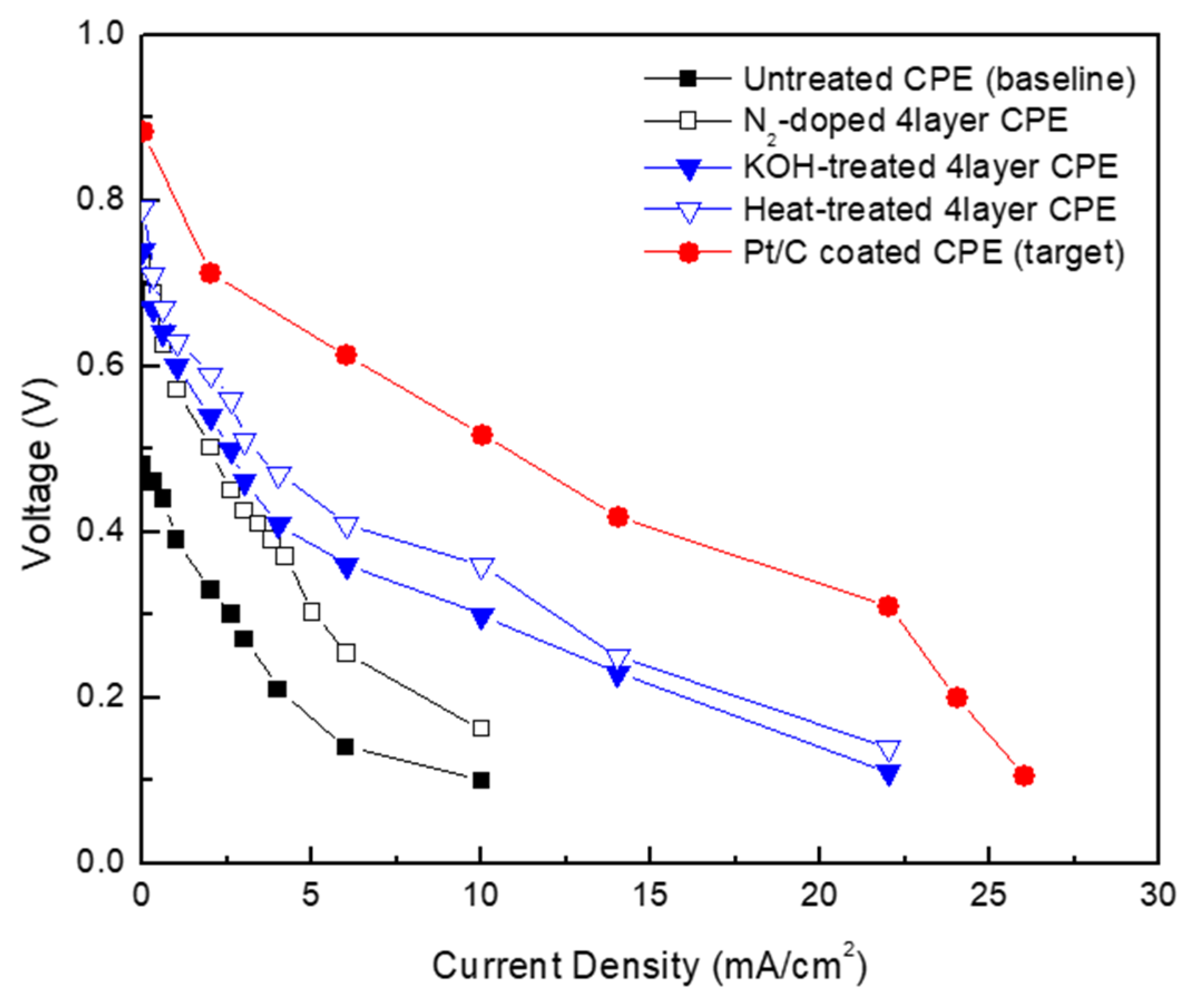
So far, the effects of various treatment methods on the cell performance have been compared, and the best conditions for each treatment have been found. In particular, the multi-layered structure was found to be effective at increasing the performance, and thus, this method was applied to the cells with the samples treated via the best pretreatment conditions (i.e., N2-doped four-layered CPE, KOH-treated four-layered CPE, and thermal-treated four-layered CPE) to further increase the cell performance. The cell performances were compared with baseline (from untreated carbon paper) and target (from Pt/C CPE) performances, as illustrated in Figure 7 and Table 1, with key performance data points.
In the case of OCV, the cell with untreated CPE produced 0.48 V (i.e., half of that of the Pt/C case), but it was improved to 0.725, 0.74, and 0.79 (64% increase) as CPE was treated with N2 doping, KOH, and the thermal method, respectively. The performance gain was also compared with the maximum current density values. It was 10 mA/cm2 for untreated CPE, but increased up to 22 mA/cm2 (120% increase) by thermal treatment, which is just 4 mA/cm2 less than that of Pt/C. The maximum power density was also compared, and it was 0.84 mW/cm2 in the baseline, but increased to 3.6 mW/cm2 (320% increase) with thermal treatment.
Even though the cell performance was significantly improved by combining the thermal treatment method and a multi-layered structure, the performance was still much lower than that of Pt/C. However, the price of Pt is several orders of magnitude higher than carbon, and therefore, the results of this research using inexpensive standard carbon paper are promising. Additionally, a further increase of OCV and kinetics is required, which may be achieved by applying carbon particles to the porous electrode to increase the reaction area, as shown in the literature [35].
4. Conclusions
In this study, alkaline alcoholic fuel cells (AFC) were investigated as a promising system to replace the conventional battery systems due to their benefits of continuous electricity generation without the need for long-time charge and the light weight of the system. The possibility of replacing the Pt-based electrode with a carbon porous electrode for an oxygen reduction reaction was studied with cell-based tests. Various methods, such as thermal treatment, KOH treatment, the N2 doping method, and reaction-area control via a multi-layered structure, were utilized to increase the reactivity of the carbon electrode, and the characteristic electrochemical reactive behaviors of the carbon electrodes treated by each method were analyzed.
It was found that the activation and mass transfer properties were significantly enhanced through the thermal treatment method, whereas a simple voltage shift without a sensible change of other properties was found from the treatment of KOH and the multi-layered electrode. Harsh treatment conditions, such as thermal treatment (i.e., thermal oxidation) at 500 °C for longer than 20 h and N2 doping at 900 °C for longer than 20 h, were found to degrade the carbon porous electrode significantly, resulting in a substantial drop in the cell performance. Therefore, those conditions should be avoided.
A significant improvement in the cell performance was achieved (2.3 times increase of max power density) by commercially available carbon papers prepared with methods defined in this study, providing a new direction of research in which conventional carbon papers are used as a promising electrode for alkaline AFC. However, the performance was still much lower than that of Pt/C, and a further increase of the cell performance is required to replace the Pt/C-electrode, which represents the future work.
Author Contributions
Conceptualization, K.T.C.; methodology, K.T.C. and D.H.P.; software, D.H.P.; validation, D.H.P.; formal analysis, K.T.C. and D.H.P.; investigation, D.H.P.; resources, T.X. and K.T.C.; data curation, D.H.P.; writing—original draft preparation, D.H.P. and K.T.C.; writing—review and editing, K.T.C. and T.X.; visualization, K.T.C.; supervision, K.T.C. and T.X.; project administration, K.T.C.; funding acquisition, K.T.C.
Funding
This research was funded by Northern Illinois University, Research and Artistry grant 2016.
Acknowledgments
The authors would like to thank the Chemistry Department at NIU for access to the equipment used in this study and technical support.
Conflicts of Interest
The authors declare no conflicts of interest. The funders had no role in the design of the study; in the collection, analyses, or interpretation of data; in the writing of the manuscript, or in the decision to publish the results.
References
- An, L.; Zhao, T.S.; Li, Y.S. Carbon-neutral sustainable energy technology: Direct ethanol fuel cells. Renew. Sustain. Energy Rev. 2015, 50, 1462–1468. [Google Scholar] [CrossRef]
- Zhiani, M.; Gasteiger, H.A.; Piana, M.; Catanorchi, S. Comparative study between platinum supported on carbon and non-noble metal cathode catalyst in alkaline direct ethanol fuel cell (ADEFC). Int. J. Hydrog. Energy 2011, 36, 5110–5116. [Google Scholar] [CrossRef]
- García-Nieto, D.; Barragán, V.M. A comparative study of the electro-osmotic behavior of cation and anion exchange membranes in alcohol-water media. Electrochim. Acta 2015, 154, 166–176. [Google Scholar] [CrossRef]
- Hou, H.; Sun, G.; Wu, Z.; Jin, W.; Xin, Q. Zirconium phosphate/Nafion115 composite membrane for high-concentration DMFC. Int. J. Hydrog. Energy 2008, 33, 3402–3409. [Google Scholar] [CrossRef]
- Hou, H.; Wang, S.; Jin, W.; Jiang, Q.; Sun, L.; Jiang, L.; Sun, G. KOH modified Nafion112 membrane for high performance alkaline direct ethanol fuel cell. Int. J. Hydrog. Energy 2011, 36, 5104–5109. [Google Scholar] [CrossRef]
- Goswami, G.K.; Nandan, R.; Barman, B.K.; Nanda, K.K. Excellent performance of Pt-free cathode in alkaline direct methanol fuel cell at room temperature. J. Mater. Chem. A 2013, 1, 3133–3139. [Google Scholar] [CrossRef]
- Lee, K.; Zhang, L.; Zhang, J. A novel methanol-tolerant Ir-Se chalcogenide electrocatalyst for oyxgen reduction. J. Power Sour. 2007, 165, 108–113. [Google Scholar] [CrossRef]
- Liu, G.; Zhang, H.M.; Wang, M.R.; Zhong, H.X.; Chen, J. Preparation, characterization of ZrOxNy/C and its application in PEMFC as an electrocatalyst for oxygen reduction. J. Power Sour. 2007, 172, 503–510. [Google Scholar] [CrossRef]
- Wang, S.; Zhao, X.; Cochell, T.; Manthiram, A. Nitrogen-Doped Carbon Nanotube/Graphite Felts as Advanced Electrode Materials for Vanadium Redox Flow Batteries. J. Phys. Chem. Lett. 2012, 3, 2164–2167. [Google Scholar] [CrossRef]
- Shen, L.; Zhang, X.; Li, H.; Yuan, C.; Cao, G. Design and Tailoring of a Three-Dimensional TiO2–Graphene–Carbon Nanotube Nanocomposite for Fast Lithium Storage. J. Phys. Chem. Lett. 2011, 2, 3096–3101. [Google Scholar] [CrossRef]
- Kannan, R.; Aher, P.P.; Palaniselvam, T.; Kurungot, S.; Kharul, U.K.; Pillai, V.K. Artificially Designed Membranes Using Phosphonated Multiwall Carbon Nanotube−Polybenzimidazole Composites for Polymer Electrolyte Fuel Cells. J. Phys. Chem. Lett. 2010, 1, 2109–2113. [Google Scholar] [CrossRef]
- Sun, B.; Skyllas-Kazacos, M. Modification of graphite electrode materials for vanadium redox flow battery application—I. Thermal treatment. Electrochim. Acta 1992, 37, 1253–1260. [Google Scholar] [CrossRef]
- Liu, Q.H.; Grim, G.M.; Papandrew, A.B.; Turhan, A.; Zawodzinski, T.A.; Mench, M.M. High Performance Vanadium Redox Flow Batteries with Optimized Electrode Configuration and Membrane Selection. J. Electrochem. Soc. 2012, 159, A1246–A1252. [Google Scholar] [CrossRef]
- Pezeshki, A.M.; Clement, J.T.; Veith, G.M.; Zawodzinski, T.A.; Mench, M.M. High performance electrodes in vanadium redox flow batteries through oxygen-enriched thermal activation. J. Power Sour. 2015, 294, 333–338. [Google Scholar] [CrossRef] [Green Version]
- Cho, K.T.; Ridgway, P.; Weber, A.Z.; Haussener, S.; Battaglia, V.; Srinivasan, V. High Performance Hydrogen/Bromine Redox Flow Battery for Grid-Scale Energy Storage. J. Electrochem. Soc. 2012, 159, A1806–A1815. [Google Scholar] [CrossRef]
- Cho, K.T.; Albertus, P.; Battaglia, V.; Kojic, A.; Srinivasan, V.; Weber, A.Z. Optimization and Analysis of High-Power Hydrogen/Bromine-Flow Batteries for Grid-Scale Energy Storage. Energy Technol. 2013, 1, 596–608. [Google Scholar] [CrossRef]
- Karim, N.A.; Kamarudin, S.K. An overview on non-platinum cathode catalysts for direct methanol fuel cell. Appl. Energy 2013, 103, 212–220. [Google Scholar] [CrossRef]
- Gojković, S.L.; Gupta, S.; Savinell, R.F. Heat-treated iron(III) tetramethoxyphenyl porphyrin chloride supported on high-area carbon as an electrocatalyst for oxygen reduction: Part III. Detection of hydrogen-peroxide during oxygen reduction. Electrochim. Acta 1999, 45, 889–897. [Google Scholar] [CrossRef]
- Gojković, S.L.; Gupta, S.; Savinell, R.F. Heat-treated iron(III) tetramethoxyphenyl porphyrin chloride supported on high-area carbon as an electrocatalyst for oxygen reduction: Part II. Kinetics of oxygen reduction. J. Electroanal. Chem. 1999, 462, 63–72. [Google Scholar] [CrossRef]
- Praats, R.; Kruusenberg, I.; Käärik, M.; Joost, U.; Aruväli, J.; Paiste, P.; Saar, R.; Rauwel, P.; Kook, M.; Leis, J.; et al. Electroreduction of oxygen in alkaline solution on iron phthalocyanine modified carbide-derived carbons. Electrochim. Acta 2019, 299, 999–1010. [Google Scholar] [CrossRef]
- Yoshinaga, N.; Sugimoto, W.; Takasu, Y. Oxygen reduction behavior of rutile-type iridium oxide in sulfuric acid solution. Electrochim. Acta 2008, 54, 566–573. [Google Scholar] [CrossRef] [Green Version]
- Li, X.; Huang, Q.; Zou, Z.; Xia, B.; Yang, H. Low temperature preparation of carbon-supported PdCo alloy electrocatalysts for methanol-tolerant oxygen reduction reaction. Electrochim.Acta 2008, 53, 6662–6667. [Google Scholar] [CrossRef]
- Zhang, Z.; Wang, X.; Cui, Z.; Liu, C.; Lu, T.; Xing, W. Pd nanoparticles supported on WO3/C hybrid material as catalyst for oxygen reduction reaction. J. Power Sour. 2008, 185, 941–945. [Google Scholar] [CrossRef]
- El-Deab, M.S.; Ohsaka, T. Hydrodynamic voltammetric studies of the oxygen reduction at gold nanoparticles-electrodeposited gold electrodes. Electrochim. Acta 2002, 47, 4255–4261. [Google Scholar] [CrossRef]
- Vázquez-Huerta, G.; Ramos-Sánchez, G.; Rodríguez-Castellanos, A.; Meza-Calderón, D.; Antaño-López, R.; Solorza-Feria, O. Electrochemical analysis of the kinetics and mechanism of the oxygen reduction reaction on Au nanoparticles. J. Electroanal. Chem. 2010, 645, 35–40. [Google Scholar] [CrossRef]
- Sung, H.; Sharma, M.; Jang, J.; Lee, S.-Y.; Choi, M.; Lee, K.; Jung, N. Boosting the oxygen reduction activity of a nano-graphene catalyst by charge redistribution at the graphene–metal interface. Nanoscale 2019, 11, 5038–5047. [Google Scholar] [CrossRef]
- Lee, H.J.; Kim, H. Graphite Felt Coated with Dopamine-Derived Nitrogen-Doped Carbon as a Positive Electrode for a Vanadium Redox Flow Battery. J. Electrochem. Soc. 2015, 162, A1675–A1681. [Google Scholar] [CrossRef]
- Babel, K.; Jurewicz, K. KOH activated carbon fabrics as supercapacitor material. J. Phys. Chem. Solids 2004, 65, 275–280. [Google Scholar] [CrossRef]
- Sun, B.; Skyllas-Kazacos, M. Chemical modification of graphite electrode materials for vanadium redox flow battery application—Part II. Acid treatments. Electrochim. Acta 1992, 37, 2459–2465. [Google Scholar] [CrossRef]
- Marma, K.; Kolli, J.; Cho, K.T. Membrane-Less Hydrogen Iron Redox Flow Battery. J. Electrochem. Energy. Conv. Stor. 2019, 16, 011005. [Google Scholar] [CrossRef]
- Jin, J.; Tanaka, S.; Egashira, Y.; Nishiyama, N. KOH activation of ordered mesoporous carbons prepared by a soft-templating method and their enhanced electrochemical properties. Carbon 2010, 48, 1985–1989. [Google Scholar] [CrossRef]
- Lv, Y.; Zhang, F.; Dou, Y.; Zhai, Y.; Wang, J.; Liu, H.; Xia, Y.; Tu, B.; Zhao, D. A comprehensive study on KOH activation of ordered mesoporous carbons and their supercapacitor application. J. Mater. Chem. 2011, 22, 93–99. [Google Scholar] [CrossRef]
- Mathias, M.F.; Roth, J.; Fleming, J.; Lehnert, W. Diffusion media materials and characterisation. In Handbook of Fuel Cells; Wiley: Hoboken, NJ, USA, 2010; ISBN 978-0-470-97400-1. [Google Scholar]
- Aaron, D.S.; Liu, Q.; Tang, Z.; Grim, G.M.; Papandrew, A.B.; Turhan, A.; Zawodzinski, T.A.; Mench, M.M. Dramatic performance gains in vanadium redox flow batteries through modified cell architecture. J. Power Sour. 2012, 206, 450–453. [Google Scholar] [CrossRef]
- Tucker, M.C.; Srinivasan, V.; Ross, P.N.; Weber, A.Z. Performance and cycling of the iron-ion/hydrogen redox flow cell with various catholyte salts. J. Appl. Electrochem. 2013, 43, 637–644. [Google Scholar] [CrossRef]
Figure 1.
Schematic diagram of the test setup of an alkaline alcohol fuel cell.

Figure 2.
Baseline and target performance of an alkaline alcoholic fuel cell. Baseline performance was obtained from a cell with an untreated cathode carbon porous electrode (CPE), and the target performance was obtained from a cell of a Pt supported on carbon (Pt/C) cathode CPE.
Figure 2.
Baseline and target performance of an alkaline alcoholic fuel cell. Baseline performance was obtained from a cell with an untreated cathode carbon porous electrode (CPE), and the target performance was obtained from a cell of a Pt supported on carbon (Pt/C) cathode CPE.

Figure 3.
Effect of thermal treatment on the cell performance for various treatment conditions. The performances were measured with cells having cathode carbon porous electrode (CPE) samples treated at various thermal treatment conditions.
Figure 3.
Effect of thermal treatment on the cell performance for various treatment conditions. The performances were measured with cells having cathode carbon porous electrode (CPE) samples treated at various thermal treatment conditions.

Figure 4.
Effect of KOH-treatment of the carbon porous electrode (CPE) on the cell performance. The treatment was conducted by submerging CPE in KOH solution overnight and then thermally treating it in an argon environment.
Figure 4.
Effect of KOH-treatment of the carbon porous electrode (CPE) on the cell performance. The treatment was conducted by submerging CPE in KOH solution overnight and then thermally treating it in an argon environment.

Figure 5.
Effect of nitrogen-doping of the carbon porous electrode (CPE) on the cell performance. The cell performance was decreased as the treatment time increased, which is due to degradation of the carbon matrix.
Figure 5.
Effect of nitrogen-doping of the carbon porous electrode (CPE) on the cell performance. The cell performance was decreased as the treatment time increased, which is due to degradation of the carbon matrix.

Figure 6.
Effect of the thickness of the carbon porous electrode (CPE) on the cell performance. The thickness of the electrode was controlled by stacking sheets of carbon paper to make the multi-layered structure.
Figure 6.
Effect of the thickness of the carbon porous electrode (CPE) on the cell performance. The thickness of the electrode was controlled by stacking sheets of carbon paper to make the multi-layered structure.

Figure 7.
Performance comparison for cells consisting of an untreated carbon porous electrode (CPE), N2-doped CPE, KOH-treated CPE, thermal-treated CPE, and Pt supported on carbon (Pt/C)-coated CPE as a cathode electrode. Especially, four layers of treated carbon papers were stacked to make multi-layered electrodes for the cases of N2-doped CPE, KOH-treated CPE, and thermal-treated CPE.


Table 1.
Comparison of the open circuit voltage, maximum current density, and maximum power density for cells consisting of five different carbon porous electrodes as cathode electrodes.
Table 1.
Comparison of the open circuit voltage, maximum current density, and maximum power density for cells consisting of five different carbon porous electrodes as cathode electrodes.
| Performance | Untreated CPE | N2-Doped CPE | KOH-Treated CPE | Thermal Treated CPE | Pt/C-Coated CPE |
|---|---|---|---|---|---|
| Open Circuit Voltage (V) | 0.48 | 0.725 | 0.74 | 0.79 | 0.88 |
| Max Current Density (mA/cm2) | 10 | 10 | 22 | 22 | 26 |
| Max Power Density (mW/cm2) | 0.84 | 1.62 | 3.24 | 3.6 | 6.82 |
© 2019 by the authors. Licensee MDPI, Basel, Switzerland. This article is an open access article distributed under the terms and conditions of the Creative Commons Attribution (CC BY) license (http://creativecommons.org/licenses/by/4.0/).
Share and Cite
MDPI and ACS Style
Perugupalli, D.H.; Xu, T.; Cho, K.T. Activation of Carbon Porous Paper for Alkaline Alcoholic Fuel Cells. Energies 2019, 12, 3207. https://doi.org/10.3390/en12173207
AMA Style
Perugupalli DH, Xu T, Cho KT. Activation of Carbon Porous Paper for Alkaline Alcoholic Fuel Cells. Energies. 2019; 12(17):3207. https://doi.org/10.3390/en12173207
Chicago/Turabian StylePerugupalli, Deva Harsha, Tao Xu, and Kyu Taek Cho. 2019. "Activation of Carbon Porous Paper for Alkaline Alcoholic Fuel Cells" Energies 12, no. 17: 3207. https://doi.org/10.3390/en12173207
Note that from the first issue of 2016, this journal uses article numbers instead of page numbers. See further details here.