Article

Evaluation of the Economic and Environmental Performance of Low-Temperature Heat to Power Conversion using a Reverse Electrodialysis – Multi-Effect Distillation System

by
Michael Papapetrou
1,2,
George Kosmadakis
3,4,*,
Francesco Giacalone
1,
Bartolomé Ortega-Delgado
1,
Andrea Cipollina
1,
Alessandro Tamburini
1 and
Giorgio Micale
1
1
Dipartimento di Ingegneria, Università degli Studi di Palermo, Viale delle Scienze, Ed.6., 90128 Palermo, Italy
2
Wirtschaft und Infrastruktur GmbH & Co Planungs-KG (WIP), Sylvensteinstr. 2, 81369 Munich, Germany
3
Ricreation IKE, Technological Park “Lefkippos”, Patriarchou Grigoriou & Neapoleos 27, 15341 Agia Paraskevi, Greece
4
Thermal Hydraulics and Multiphase Flow Laboratory, INRASTES, National Center for Scientific Research “Demokritos”, Patriarchou Grigoriou & Neapoleos 27, 15341 Agia Paraskevi, Greece
*
Author to whom correspondence should be addressed.
Energies 2019, 12(17), 3206; https://doi.org/10.3390/en12173206
Submission received: 24 July 2019 / Revised: 12 August 2019 / Accepted: 16 August 2019 / Published: 21 August 2019
(This article belongs to the Section A: Sustainable Energy)

Abstract

:
In the examined heat engine, reverse electrodialysis (RED) is used to generate electricity from the salinity difference between two artificial solutions. The salinity gradient is restored through a multi-effect distillation system (MED) powered by low-temperature waste heat at 100 °C. The current work presents the first comprehensive economic and environmental analysis of this advanced concept, when varying the number of MED effects, the system sizing, the salt of the solutions, and other key parameters. The levelized cost of electricity (LCOE) has been calculated, showing that competitive solutions can be reached only when the system is at least medium to large scale. The lowest LCOE, at about 0.03 €/kWh, is achieved using potassium acetate salt and six MED effects while reheating the solutions. A similar analysis has been conducted when using the system in energy storage mode, where the two regenerated solutions are stored in reservoir tanks and the RED is operating for a few hours per day, supplying valuable peak power, resulting in a LCOE just below 0.10 €/kWh. A life-cycle assessment has been also carried out, showing that the case with the lowest environmental impact is the same as the one with the most attractive economic performance. Results indicate that the material manufacturing has the main impact; primarily the metallic parts of the MED. Overall, this study highlights the development efforts required in terms of both membrane performance and cost reduction, in order to make this technology cost effective in the future.

1. Introduction

There are very large amounts of waste heat that remain unexploited all over the world. It is estimated that in the EU industries alone, the recoverable part of that heat is about 300 TWh/year [1]. The main focus is on industrial waste heat that is mostly available at a temperature of over 100 °C and represents a significant fraction of the total. Various technologies are developed to exploit this heat and convert it into useful energy, with the main concepts dealing with the production of power/electricity [2] or upgraded heat [3]. Especially, the heat-to-power concept has attracted most of the attention [4], with various heat engines developed that can exploit this low-temperature heat source and convert it into power [5]. The most common one is a heat engine based on the organic Rankine cycle (ORC), which has reached commercial level and is applied in various industries and temperature ranges [6]. Other heat engines have been also developed, attempting to offer improved performances or lower costs than the ORC one.
One alternative with increasing research interest is the salinity gradient power heat engine (SGP-HE) [7]. This system consists of: (1) a power unit based on salinity gradient power, technology, in which the chemical energy associated to the mixing of two solutions at different salt concentrations is converted into electricity, and (2) a regeneration unit, where (waste) heat is used to restore the original concentration of the two solutions. Reverse electrodialysis (RED) is one of the main technologies for exploiting SGP and uses membranes that are selective towards the passage of ions, employed in a stack, which is composed of a series of anion and cation exchange membranes arranged in an alternate way. RED has been examined extensively in open-loop configuration, using natural streams (e.g., seawater and river water) [8,9] or streams deriving from human activity, such as brines [9,10]. In order to operate in a closed-loop with artificial solutions, the two solutions after passing the RED membrane stack need to be regenerated using a thermal separation system driven by waste heat to restore the initial salinity gradient [11,12].
The most suitable thermal separation technology, considering the heat supply of low-temperature heat at 100 °C, is multi-effect distillation (MED). MED is widely applied in desalination and other water treatment plants and is mostly applicable in cases with distilled flow rate over 5000 m3/day, while small-scale designs have been also proposed [13]. The use of a large number of effects improves the thermal efficiency but also drives up the heat exchanging surface and the capital cost. This issue has been examined in [14], developing a detailed correlation to estimate the MED capital cost, including various parameters that are of use here. Except for MED, other separation technologies suitable for the RED heat engine are based on membrane distillation (MD) [12] or distillation columns with thermolytic salts [15], which show a lower potential due to their higher thermal energy consumption and specific capital cost [16,17].
Most of the works reported in the literature relevant to SGP-HE have focused on the use of sodium chloride salt-solutions [16,18,19]. However, the adoption of alternative salts, such as lithium chloride or potassium and cesium acetate has the potential to increase the performance of the RED-MED thanks to their high solubility [20]. Further performance improvements can also be obtained by operating the RED unit at temperatures higher than the ambient one [21]. The impact of both improvements is considered in the present work by operating the RED unit at three different temperatures (i.e., 25 °C, 50 °C, and 80 °C) and by considering either sodium chloride (NaCl) or potassium acetate (KAc) as working solutions of the RED-MED.
The cost effectiveness of the open loop RED has been already examined [9,22], showing that further technological improvement is necessary before it can be cost-effective, related to the development of membranes with higher performance and lower cost. The closed-loop RED employing a regeneration stage is a more recent concept, with the studies conducted so far focusing on the solution specifications, temperature of the driving heat, cycle design, and the regeneration unit. An alternative regeneration unit is membrane distillation, which is especially suited for small-scale applications. The economics of the RED-MD system were examined in Ref. [16] and it was shown that if high-performing ion exchange membranes (IEMs) were developed, the levelized cost of electricity (LCOE) would be around 0.40 €/kWh. This could be further reduced to values in the range of 0.10 to 0.25 €/kWh, assuming important reductions in membrane and MD costs in the future in the case of industrial-scale production.
The main purpose of the current work is to assess the capital and running costs of the RED-MED heat engine configuration and to calculate its levelized cost of electricity. A first indication has been provided in Ref. [23] for a specific case and size with standard conditions (i.e., sodium chloride solutions and ambient temperature in the RED unit). Here, further details are examined, focusing on high-performing configurations, introducing the main parameters that affect the cost, such as the system scale, salt used, RED operating temperature, and the number of MED effects, with the aim to provide a more comprehensive approach in this field than existing relevant studies. Appropriate cost correlations are used for that purpose while examining the cost variation of the IEMs and of the MED. The case with the superior cost-effectiveness has been further examined in storage mode for calculating the LCOE for supplying peak power at times of high electricity prices.
Apart from the cost analysis, the life cycle assessment (LCA) methodology is used for assessing the environmental impacts of the different RED-MED system configurations. By accounting for the impacts throughout the system’s life cycle, the risk of missing any environmental trade-offs that could occur between the different life cycle phases is avoided [24]. When looking at the conversion of low-temperature heat to electricity, most LCA studies are related to the ORC, focusing either on design aspects, such as in Ref. [25], where the impacts of using different working fluids are compared, or on the application context, such as in Ref. [26], where the impacts of using ORC to convert the waste heat from a biogas plant to electricity are explored.
The novelty of the current work is strengthened by the absence of similar studies on the environmental impacts of the RED heat engine. An overview of potential environmental concerns of RED and other SGP processes have been outlined in Ref. [27], but the focus was mostly on open loop applications and the impacts from the use of natural streams to feed the process (e.g., river water with seawater). The only study that is related to the present one is the work on an osmotic heat engine [28], where pressure-retarded osmosis (instead of RED) is used for power generation, operating in a closed loop and using MD powered by waste heat for the regeneration process. In that paper, the life-cycle impacts from converting waste heat to electricity are assessed, comparing the options of using an osmotic heat engine or an ORC for converting waste heat to electricity.

2. RED-MED Configurations and Performance Analysis

The initial performance calculations assume that the system uses commercially available IEMs. The permselectivity, electrical resistance, salt permeability, and water permeability of the specific membranes considered (reference values) have been presented as a function of the temperature in Ref. [21]. In this initial calculation, a large number of MED effects is considered, since the aim was to maximize the thermal efficiency of the heat engine.
In order to examine different cases that affect the financial and environmental impacts, a variety of configurations have been considered, as follows:
  • The use of improved IEMs in the RED stack, referred to as “high-performing” membranes, whose properties are reported in Table 1 and are in line with several high-performing IEMs available in the market [16].
  • The use of a lower number of effects in the MED process, reducing from 24 (best performing case for NaCl salt and reference IEMs presented in Ref. [21]) to six (lowest LCOE achieved). This decreases the thermal efficiency, requiring more heat for generating the same amount of electricity. At the same time, it also reduces the surface of the heat exchangers (HEX) of the MED for producing the same amount of electricity. This is beneficial for both the system cost [14] and the environmental performance, by using less metallic materials (e.g., copper and nickel) that have significant environmental impact. Reducing the number of effects below six has been considered in the simulations, but it was observed that for an even lower number of effects, the LCOE starts increasing again. This is because after a certain point the loss of efficiency starts counterbalancing the saving on material cost, leading to an optimum at around six effects (depending on the size of the system, but usually in the range of 5–7).
  • The use of KAc–water solutions as an alternative working fluid to NaCl–water solutions.
  • The operation of the RED stack at elevated temperature (reheating option) up to 80 °C, for improving the system efficiency [8].
The combination of these alternative options together with the initial reference case add up to a total of six RED-MED configurations considered in this work. An overview is provided in Table 2, all supplied with waste heat at a temperature of 100 °C. Further details of the IEM types with their properties are provided in Ref. [21].
For each of these configurations, the system performance has been calculated for a single RED stack, with 1000 cell pairs and a surface of 0.25 m2 per membrane. The full technical analysis, description of the model used, and results are provided in Ref. [21]. An overview of the system’s performance parameters with one stack for each configuration/case are provided in Table 3. These results are used as input in the cost analysis model to perform the LCOE calculations. The thermal efficiency is defined as the ratio of net power production to the heat input, including the heating of the solutions entering the stacks for cases 5 and 6.
The high-performing membranes bring more than a three-fold power production increase, and the use of KAc instead of NaCl accompanied by the reheating option greatly increases the thermal efficiency, reaching a value of 5.5%. This value is similar or even slightly higher compared to the ORC technology for the same heat source temperature of 100 °C [29,30,
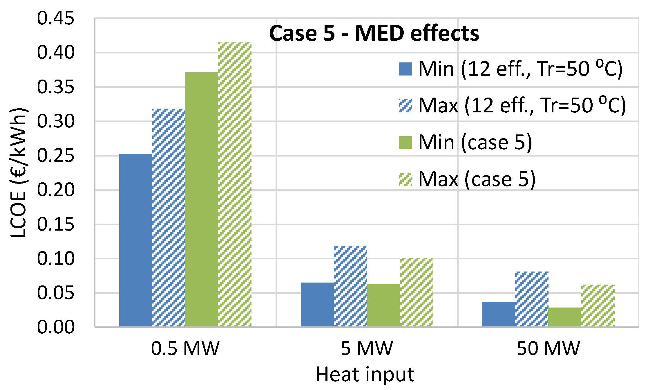
31]. The thermal efficiency of the RED-MED system under cases 5 and 6 can be increased further, reaching values of about 10%, as presented in Ref. [21], for a high number of MED effects. This high-efficiency option is examined further in Section 5.4. For comparison, the Carnot efficiency for these temperatures is 20.1%.
For all configurations examined, a thorough cost analysis has been conducted based on the methodology presented in Section 3. These results are presented in Section 5 and are supported with an LCA described in Section 4, in order to evaluate this technology from an environmental impact perspective.

3. Economic Analysis

3.1. Overview of the Methodology

The economic analysis of the RED heat engine is based on the calculation of the levelized cost of electricity, which provides a reliable way of estimating the potential of various power production technologies [32]. The LCOE is calculated from Equation (1).
L C O E = t = 0 n I t + M t ( 1 + r ) t t = 0 n E t ( 1 + r ) t
where t refers to the year, with t = 0 representing the start of the plant construction requiring one whole year, n is the plant lifetime, It are the investment expenditures (capital costs) in the year “t”, Mt are the running costs (fixed and variable) in the year “t”, r is the discount rate, and Et is the electricity generation (in kWh) in the year “t”, calculated according to the capacity factor and the net power production.
The parameters considered for the cost analysis and included in Equation (1) are given in Table 4, according to assumed financial conditions for discount rate and cost factors of power plants. A capacity factor of 90% (percentage of operating hours during a year) was considered for the calculation of the electric energy generation of the RED unit. A variable IEM specific cost is used, with its upper limit (30 €/m2) corresponding to current prices, and its lowest value is 1 €/m2. This extremely low value is used in order to examine the complete potential, although a more realistic target would be to expect the IEM costs to fall in the range of 5–10 €/m2 when the technology further develops and the full benefit of economies of scale can be achieved at industrial membrane production sites. The MED specific cost reduction is a parameter that is added for taking into account possible future cost reductions of this technology, as explained later in Section 3.2.2. Finally, the IEM lifetime is considered in all cases to be 10 years. This is a reasonable assumption, based on the fact that artificial (clean) solutions are used in a closed loop configuration. In any case, reducing the lifetime of the IEMs to 5 years (50% reduction) would increase the LCOE by less than 10% for the highest IEM specific cost. For the lowest IEM specific cost, this LCOE increase is negligible.

3.2. Capital Costs

The capital costs of the system include (i) the RED stacks capital cost, (ii) the MED capital cost, and (iii) other capital costs required to operate the system. The main contributions to the total capital cost (CAPEX) derive from the RED stacks and the MED unit. These costs are presented next, together with the other (minor) costs, leading to the specific capital cost expressed in €/kWe of net capacity.

3.2.1. RED Stack Capital Cost

A variable IEM specific cost is introduced in the calculations (see Table 4) in order to identify the cost ranges, which can make this technology financially viable. These ranges are very wide, in order to identify the targeted future specific costs.
In addition to the IEMs, the cost of the stacks and the electrodes are taken into account. Their current specific cost has been considered to be 15.5 €/m2 of membrane surface, equal to 51.7% of the current membrane cost (assuming a stack size of 1000 cell pairs with 0.25 m2 membrane surface). This fraction is kept constant in this work, since the cost reduction of the stacks and electrodes is expected to follow a similar trend to the cost reduction of the IEMs.

3.2.2. MED Capital Cost

The MED specific capital cost ( C M E D ) is calculated based on a detailed correlation that has been developed by some of the authors recently [14], and takes into account the heat source temperature, number of effects, and scale. Its simplified expression is given by Equation (2).
C M E D = 6291 D 0.135 [ ( 1 f H E X ) + f H E X ( N N r e f ) 1.277 ( T r e f T ) 1.048 ]
where D is the distillate flow rate in m3/day, fHEX is the cost contribution of the heat exchangers to the MED cost equal to 40% [33], N and T are the number of effects and the temperature of the external heat source of the MED, while Nref and Tref are the reference number of effects equal to 8 and the reference temperature of the heat source equal to 70 °C respectively.
This correlation provides the MED capital cost for desalination applications. However, some components of the desalination plants are not used in the current configuration, such as the intake and outfall infrastructure (the RED-MED system operates in a closed-loop), reducing the MED cost by 35%, according to Sommariva [33].
A cost reduction of MED units is possible in the future because of technology developments, such as the use of advanced manufacturing process for the heat exchangers and the possible use of polymeric composite materials for the tubes [34]. In order to introduce all the above in the calculations, a (variable) cost reduction fraction of MED is included in the methodology, which decreases its current capital cost by values of up to 50%.

3.2.3. Other Capital Costs

Other relevant costs include the capital expenditure for pumps, inverter, piping, civil & electrical infrastructure, and other minor costs (e.g., salt cost). The pump and piping costs are calculated according to Ref. [2], while the inverter specific cost (Cinv) is given as a function of gross power production (Pg) according to a market research for both single-phase and three-phase inverters, using Equation (3).
C i n v = 536.96 ( P g ) 0.408
The civil and electrical infrastructure costs are calculated using a specific value of 250 €/kWe of net power production [35].

3.3. Operating and Maintenance Costs

The operating costs (Ot) are estimated as a function of the net power production (in €/kW/year), equal to: O t = 4000 ( P n e t ) 0.5 , after processing the reported (fixed) operating costs of renewable energy and waste heat recovery power systems [36,37]. The maintenance costs include the IEM’s replacement for materials (using the same IEM specific cost and a lifetime of 10 years, see Table 1) and the associated labor cost. The sum of these three costs is considered as the OPEX of the plant. The RED heat engine exploits waste heat; therefore, no additional cost exists relevant to the heat/fuel supply.

3.4. Additional Capital Costs in Energy Storage Mode

The system configuration can be adjusted to operate in an energy storage mode for supplying peak power. This is possible by including two reservoir tanks for storing the two solutions of low and high concentration after they are regenerated in the MED unit, and another two for the return, as shown in Figure 1. The size of these tanks is varied to store the necessary quantities, according to a parameter that expresses the time fraction that the RED stacks operate and produce power (100% at continuous operation, less than 100% at energy storage mode). Therefore, the capacity of the RED stacks is increased proportionally in this mode, while the MED unit operates continuously (as long as waste heat is available). A very important feature of this technology is that it shows no losses of its storage efficiency, as with many other storage systems, since the potential energy is stored in the form of salinity difference between the two solutions in the tanks.
For analyzing the cost effectiveness of this mode, the same approach is followed as presented in the previous sections. The amount of working fluid and salt increase accordingly, having a negligible effect on the capital cost. The main additional cost introduced in this mode, apart from the increased RED cost because of its larger capacity, is the tanks’ cost (four tanks in total). The specific cost of these storage (reservoir) tanks (Ctank) is estimated as a function of their storage capacity (Qc) according to the results of a recent study [38], as shown in Figure 2.
These results have been fitted for the production of a correlation with R2 approaching unity, given by Equation (4).
C t a n k = 17137 ( Q c ) 0.551
This correlation is included in the cost analysis model for calculating the cost of the storage tanks of the solutions.

4. Environmental Assessment

4.1. Overview of the Methodology

This part of the work has been carried out adhering to the International Standard EN ISO 14044:2006 [39] presenting the four standard phases: (i) definition of goal and scope; (ii) life cycle inventory analysis; (iii) life cycle impact Assessment; and (iv) life cycle interpretation. In this work, the presentation has been summarized for fitting the paper structure, including the scope of the study and main assumptions in Section 4.2 and the main results in Section 5.
The methodology proposed by Gerber et al. [40] was adopted here. The main improvement of that approach compared to standard LCAs is that the flows of the LCA model are expressed as functions of the technical parameters (e.g., number of MED effects, salt used) allowing us to easily study how the impacts when changing the system design or operating conditions. This approach has been implemented within a model developed in GaBi software [41].

4.2. Scope of the Study, Assumptions, and Limitations

The functional unit is the net electric energy generated by the RED-MED system equal to 1 kWh. Within the boundaries, all components of the RED-MED system are included. The industrial unit that provides the waste heat or any other equipment that is needed to provide the heat is outside the boundaries of this study. Similarly, the end-user of the generated electricity is outside the boundaries, as the purpose is to compare different design configurations of the RED-MED system and to identify the best configuration in terms of environmental impact.
According to Turconi et al. [42], the most important impact categories for electricity generation technologies are: global warming, eutrophication, and acidification. For this reason, these were the three impact categories selected to be included in the current study.
The company REDstack provided the bill of materials required for constructing one RED stack. Linear scaling was assumed, which is reasonable since these stacks are modular, i.e., for larger systems more stacks are used rather than larger stacks. The company FUJIFILM provided the bill of materials used for the Ion Exchange Membranes and the electricity required for their production. Literature references have been used to fill in some gaps in the bill of materials for the overall system, such as for the MED unit, using data from Raluy et al. [43]. The GaBi database was used for the resources and the emissions associated with the extraction and processing of the raw materials required as input for the components of the RED-MED system.
It is assumed that large amounts of waste heat at 100 °C are available and there are no environmental impacts associated with them (e.g., no additional fuel is used). There is no specific location or end-user defined. The following limitations/value choices were made in this study:
  • The energy required for the assembly of the MED unit was ignored because of lack of data, but the assembly is only a small fraction of the energy required to manufacture the materials.
  • The following materials were ignored, following a cut-off rule, because their mass is less than 0.3% of the total system mass: water (0.4 kg) and salt (0.07 kg) forming the working fluid, and the titanium (3.2 kg) used for the electrodes. These quantities are scaled per stack.
  • The mass of platinum used in the electrodes (0.04 kg) is very low compared to the total system mass. The cut-off rule cannot be applied as platinum is a critical and scarce resource. However, no data was available; therefore, it was ignored. This is a limitation that has to be addressed in future research.
  • The Poly(diallyldimethylammonium chloride) used for the cation exchange membrane (CEM) was ignored as no data was available for its manufacturing. But in most cases examined, the total mass was below the 1% of the total system mass, so the impact of ignoring it is negligible.
The different cases studied are discussed in Section 2. The resulting life cycle inventory analysis for each examined case was used in the RED-MED process, which is part of the GaBi model. The relevant figures are presented in Appendix A.
In addition to the main RED-MED process, a number of auxiliary processes were introduced in the GaBi model. For all pumps, the predefined GaBi processes were used, allowing to fully account for the material used for the pump construction (the energy used by the pumps during operation has been included as internal consumption in the RED-MED process). An inverter has also been included as a separate process; the data regarding the materials are taken from Ref. [44]. An “empty” process was also introduced for splitting the AC electricity that is provided by the inverter to the part that is used to power the internal requirements of the RED-MED system, while the rest is the net electricity generated that is provided to the end-user, which is scaled to the functional unit of 1 kWh.
In addition to these processes that are directly associated with the operational phase of the system, there are separate processes included that are associated with the production of the materials required for the construction of the system, their transportation to the site they are used, and then similarly, separate processes for their transportation after the heat engine’s end-of-life and for their disposal. For all of these, standard processes have been selected from the GaBi software. All transportation processes (from production to use and from use to end-of-life) are was assumed to take place by trucks fueled by diesel and all distances were set as 600 km. Landfill disposal was assumed for all materials to account for the end of life phase.

5. Results and Discussion

5.1. RED-MED Systems

The methodology takes into account the scale of the system. The system scale is sized to match the heat input of 0.5, 5, and 50 MWth (small, medium, and large respectively), resulting in a different net power production and number of RED stacks for each configuration, given in Table 5. The number of stacks is rounded to match as closely as possible the full use of the heat value to the reference ones.
For each case, the relative contribution of the RED and MED costs on the LCOE are examined. This contribution is shown in Table 6 for a medium-scale system (heat input of 5 MWth) when using an IEM specific cost of 30 €/m2 and without any MED cost reduction.
The use of 24 MED effects for case 1 greatly increases the HEX surface, associated with a very high MED specific cost. This is beneficial for the thermal efficiency, but introduces a much larger MED unit, contributing to 64% of the total system capital cost. The other costs become important only for cases 5 and 6, partly due to the additional heat exchangers for reheating the two solutions (with surfaces of 6.2 and 29.3 m2 for these two cases respectively). For these two cases, the large contribution of the MED cost is because the RED stacks work very effectively and each stack can process a large amount of heat input, increasing the thermal efficiency, as shown in Table 3. On the other hand, cases 2–4 show a similar break-down with all cases having six MED effects.
The results for the first two cases (with reference membranes) are presented in Section 5.2 and the results with the high-performing membranes (cases 3–6) are presented in Section 5.3. The most promising configuration is selected and further detailed results are presented for this in Section 5.4, including the increase of the number of MED effects reaching maximum thermal efficiency of about 10%. In Section 5.5, the operation of the optimal configuration in storage mode is explored. Finally, the life cycle assessment of the six configurations is presented in Section 5.6.

5.2. RED-MED System for Continuous Operation with Reference Membranes

5.2.1. LCOE with Reference Membranes

The LCOE values are evaluated for power plants operating in continuous mode and with a variable heat input. By considering an IEM specific cost of 30 €/m2 and without any MED cost reduction, the resulting LCOE for cases 1–2 with reference membranes is given in Table 7.
For a small system, the use of 24 MED effects (case 1) brings a lower LCOE than with a similar system with six MED effects (case 2). This is because with the 24 effects, a higher water flow is reached out of the same amount of heat, and hence a higher MED and RED capacity compared to case 2. For these small sized MED units, the effect on the cost of the higher capacity is stronger than the effect on the cost of the higher heat exchanger surface, leading to lower specific capital costs for the MED of case 1. However, this trend is reversed for the medium and large systems, in which the MED unit is large enough and the effect of the economies of scale is weaker, with the effect of the higher heat exchanger surface playing a decisive role. In any case, the use of reference membranes leads to high LCOE values of 1.36 €/kWh in the best case, with a specific capital cost exceeding 100,000 €/kWe. The next sections further examine cases 1–2, taking into account possible future reductions in the cost of membranes, stacks, and MED units.

5.2.2. Effect of IEM Specific Cost on the LCOE with Reference Membranes

The LCOE as a function of the IEM specific cost is presented in Figure 3 for the two configurations with reference membranes (cases 1–2) and for variable heat input.
The reduction of the IEM specific cost brings a lower LCOE value; however, reducing the RED capital costs by a factor of 30 reduces the LCOE only by 2–3 times. As the scale of the system increases from the small to the large system size, the LCOE rapidly decreases by 2–5 times. This is mostly attributed to the MED cost, since its verified capital cost correlation [14] takes into account its size.
Still, even in the most favorable future cost scenarios, the LCOE remains at the levels of 0.45 €/kWh or higher, with the specific capital cost reducing to about 49,000 €/kWe. These values are far from being competitive, leading to payback periods longer than the plant’s lifetime.

5.2.3. Effect of the MED Cost Reduction on the LCOE with Reference Membranes

Next, the effect of the MED capital cost reduction compared to current prices (from 0 up to 50%) on the LCOE is examined to account for future developments in this field, while keeping a constant IEM specific cost of 30 €/m2. This effect is presented in Figure 4 for the two configurations with reference membranes and for a variable heat input.
The effect of the MED cost reduction is more pronounced in the configuration with 24 MED effects (case 1), for which the MED has a larger contribution on the total system capital cost, reducing the LCOE by up to 30%. For case 2 with six MED effects, this trend is weaker, limiting the LCOE reduction to levels between 10 and 15%. Moreover, the LCOE has very high values with the two configurations (cases 1 and 2) with reference membranes, showing that even with a large MED cost reduction, the LCOE is always over 1.20 €/kWh, with a specific capital cost of about 92,000 €/kWe.

5.2.4. Combined Effect of the IEM Specific Cost and MED Cost Reduction on the LCOE with Reference Membranes

Having identified the effect of each cost reduction measure separately, they are combined here. The resulting minimum LCOE for cases 1–2 considering both RED and MED cost variations within the whole range is presented in Table 8.
By considering both effects, it is possible to reduce the LCOE to values as low as 0.26 €/kWh for the large-scale system for case 2 (specific capital cost of 26,000 €/kWe). Even with the large cost reduction of the IEMs and the MED unit, this value is still not competitive in the current energy market, demonstrating that the performance of the IEMs should also be improved for reaching competitive solutions, as presented in the next section.

5.3. RED-MED System for Continuous Operation with High-Performing Membranes

5.3.1. Combined Effect of the IEM Specific Cost and MED Cost Reduction on the LCOE with High-Performing Membranes

The thermal efficiency greatly improves with the use of the high-performing membranes, which has an important effect on the system costs, as can be seen by the results presented in Table 9. These have been calculated with the standard (highest) cost values considered for the RED (IEMs and stack/electrodes) and the MED components.
The use of KAc (case 4) shows slightly better cost results compared to NaCl (case 3), indicating that the replacement of the salt alone is not adequate to reach low LCOE values. This should be accompanied with the reheating option, in order to utilize the larger potential of this technology. For the two cases with KAc and reheating (cases 5–6), a small variation of the LCOE is observed between them of less than 10%.
Introducing the combined contribution of the IEMs specific cost reduction potential and the MED cost reduction potential on LCOE, the results are presented in Figure 5 for cases 3–4 for the medium-scale system with heat input of 5 MWth.
The trend of the results is similar to the cases with the reference membranes. The LCOE rapidly decreases by about 50% as the IEMs specific cost is reduced
The results for cases 5–6, where the reheating of the solution is also used, are provided in Figure 6 for the medium-scale system.
For these two cases, the high cost contribution of the MED unit makes the LCOE very sensitive to the MED cost reduction effect, supported by the fact that they require less RED stacks for utilizing the heat input, as shown in Table 5. This makes it possible to reach a low LCOE of 0.08 €/kWh, even relying on current IEMs prices of 30 €/m2, corresponding to a specific capital cost of about 4000 €/kWe. In fact, for both cases 5 and 6, when using current commercial prices and without relying on any future cost reductions either for the RED or for the MED components, a LCOE of 0.09 to 0.10 €/kWh can be reached. As shown in Table 9, this reduces further to values of 0.06 €/kWh for large systems. These results indicate that future improvements in membrane performance are much more critical in the aim of reaching competitive LCOE compared to the cost of the components.
When considering both the larger system scales and the potential future cost reduction, the system cost-effectiveness is improved further, as shown in Figure 7, where the minimum calculated LCOE (considering the lowest IEM specific cost and the highest MED cost reduction) is shown for cases 3–6 for the three typical system scales.
The LCOE for the large-scale system can be reduced to half when the IEMs and MED costs are decreased to the maximum possible extent. This reduction is even adequate for case 3 to become cost-competitive, achieving a LCOE of 0.05 €/kWh, with the other three cases (cases 4–6) even lower than that, and securing a short payback period of 4–5 years when considering an electricity price of 0.10 €/kWh. The specific capital cost is then reduced to 2180 €/kWe, similar or even lower than the main competing technology of the ORC [45].
For the medium system, only cases 5 and 6 seem to have some potential. Even if the other two cases show a minimum LCOE of about 0.10 €/kWh, this involves a very large cost reduction, especially for the IEMs, which is not expected to be reached in the long-term. Therefore, for this system scale, a competitive (future) LCOE of about 0.07–0.09 €/kWh can be obtained only by cases 5 and 6 with a resulting payback period of about 10 years, which is attractive considering the system (net) capacity of 230–250 kWe and a specific capital cost of 4000–4500 €/kWe.
For the small system, no possible combination of cost reduction measures can lead to a low LCOE, which always stays above 0.33 €/kWh.
The safe conclusion reached here is that the RED-MED system is suitable only for at least medium-scale systems (as defined in this study), revealing the full technology potential as the capacity increases. For smaller systems, the RED-MD combination seems to be more suitable [16].

5.3.2. Screening of the Most Promising Case

The two best performing configurations in terms of cost-effectiveness are the ones with solution reheating (cases 5 and 6). However, the reheating at the high temperature of 80 °C is marginally beneficial for the economic performance of the system, especially at large scales. Having in mind that the increase of the reheating temperature could accelerate the ageing of the IEMs and lead to more frequent replacement, increasing the operating costs (the same lifetime of 10 years is considered for all cases). Therefore, the use of a more relaxed reheating temperature of 50 °C is favored, leading to the final screening of case 5 as the most suitable/promising configuration. Only this case will be examined in the next sections of this work.

5.4. RED-MED System of Case 5 for Continuous Operation with High-Performing Membranes

5.4.1. Detailed Cost Analysis for Various System Scales and Number of MED Effects

The further investigation of case 5 includes the more detailed assessment of the system costs for different scales and higher numbers of MED effects. Figure 8 shows the resulting LCOE range (minimum/maximum) for a higher variety of system scales, in order to identify the minimum system size for which the system can still be financially viable. The maximum LCOE corresponds to the case with no cost reduction of the MED and an IEM specific cost of 30 €/m2, while the minimum one has 50% cost reduction of the MED and an IEM specific cost of 1 €/m2.
It is clear that the system size should always correspond to a heat input of at least 2 MWth, and preferably over 5 MWth. This corresponds to a maximum LCOE of 0.15 €/kWh, reducing to below 0.07 €/kWh for larger systems, even without any future cost reduction. For heat input over 50 MW, the LCOE shows a minor reduction, since the system is already large enough, with a net power production capacity over 2.3 MWe.
A higher number of MED effects is examined next. This effect has been identified in the beginning of this work when comparing cases 1 and 2 with reference membranes. This trend is verified for case 5 as well, as shown in Figure 9 for 12 MED effects, which is the upper limit to maintain a reasonable temperature driving force in the heat exchangers of each effect.
At low scales, the variant with 12 MED effects performs better, due to the larger MED unit count lowering its specific cost. For the medium-scale system, the results are comparable (especially the minimum LCOE value), showing that the LCOE is not that sensitive to the number of effects as cases 1 and 2. However, for large systems, the use of six MED effects is preferred for reaching an even lower LCOE.

5.4.2. LCOE Comparison of Case 5 with Other Heat Engines

An alternative RED heat engine relying on a membrane distillation unit for the regeneration process was examined. For this heat engine, cost analysis has been conducted [16], resulting in LCOE values in the range of 0.10 to 0.25 €/kWh, assuming important reductions in IMEs and MD costs in the future. The RED-MED combination examined here is characterized by a superior economic performance. However, the main advantage of the RED-MD unit is the small variation of the MD unit at small scales, in which the RED-MED has very high LCOE values.
Another membrane-based heat engine is the osmotic heat engine [28]. This uses an MD unit to operate in a closed loop. Although the current LCOE of the osmotic heat engine of very large scale is about 0.48 €/kWh [46], this could be reduced to values as low as 0.10 €/kWh. Still, this value is almost double that of the LCOE of the best performing case 5 setup at similar scales.
Finally, the main competing technology is the ORC, which is capable of few kW up to several MW of power production. For the same waste heat temperature of 100 °C, the specific cost and LCOE decrease for medium-scale systems [45], reaching a specific cost of 3000 €/kWe and a LCOE of about 0.08 €/kWh [47], while for large-scale systems, the LCOE is in the range of 0.04–0.05 €/kWh [48]. The RED-MED system of case 5 has the potential to directly compete with ORC systems once the performance and cost targets are reached.

5.5. RED-MED System in Storage Mode

Having identified case 5 as the most promising configuration, the final part of the work focuses on its operation in storage mode. This mode is realized by adding two reservoir tanks to store the two solutions once they are regenerated by the MED unit, and another two for the return from the RED before entering the MED unit. Therefore, the MED continually operates, whereas the RED stacks run only when required for peak power production. The main difference with the continuous operation, except for the reservoir tanks, is that for the same MED size, more RED stacks are used to provide peak power.
The LCOE for the system in storage mode has been calculated for the medium and large-scale systems and is shown in Figure 10 as a function of the time that the RED operates (i.e., a 50% time fraction corresponds to 12 hours of power production per day, while the MED unit regenerates the solutions continually). The peak power produced by the RED stacks is also indicated in Figure 10.
For the medium-scale system, the LCOE increases as the time fraction is reduced, highlighting the cost effect of the storage tanks (their size is increased for low time fractions to store larger quantities of solutions). For a time fraction of 50%, the LCOE is within the range of 0.10–0.16 €/kWh, which can be cost competitive under specific conditions, such as high electricity prices at peak hours. These figures are improved for the large-scale system, reducing the LCOE to 0.03–0.04 €/kWh, with the minimum value being practically the same for all time fractions. The upper limit reaches 0.13 €/kWh for a 25% time fraction and remains below 0.09 €/kWh for the other time fractions. This is a very promising result—even without any expected future cost reductions for the RED and the MED components, values around 0.9 to 0.13 €/kWh for peak power can be very competitive.
Finally, the peak power production can be as high as 1 MW for the medium-scale system, increasing to 11 MW for the large one. This power production is very high compared to the available heat input (about 20%), offering important opportunities for industrial plant operators for storing their heat as a salinity gradient and releasing in the form of electricity to cover the peak demand at moments with high electricity prices [49].

5.6. Life Cycle Interpretation—Results

5.6.1. Main LCA Results

By running the GaBi model for all cases and based on the methodology and input data presented previously, the results for the main impact categories are shown in Table 10 per one kWh of electricity produced (net). The full results, including the breakdown of the relative contributions from the various materials and processes, are provided in Appendix B.
All cases give much lower impacts than case 1, with every improvement introduced in each case bringing extra environmental benefits. By reducing the number of MED effects from 24 to six (moving from case 1 to case 2), the GWP and eutrophication potential are reduced by a factor of about four, while the acidification potential is reduced by a factor of six. These reductions are directly associated to the 5.5-fold decrease in the mass of copper, nickel, and stainless steel between the two cases. The replacement of the commercial IEMs with the optimized membranes for the RED-MED system (moving from case 2 to case 3) brings a reduction by a factor of about 6.3 for all impact categories; a result of the six-fold increase of the system’s power. When moving from case 3 to case 4, i.e., replacing NaCl with KAc, the impact reduction across all categories is about 1.2, again aligned with the power increase between these two cases. By increasing the temperature of the RED solution from 25 to 50 °C (from case 4 to case 5), the GWP and eutrophication potential are reduced by a factor of about two, while the acidification potential is reduced by a factor of about 1.5. These improvements are much lower than the five-fold increase in power output, because the total mass of the metals (for the MED and for the reheaters to increase the solution temperature) increases by a factor of over three between these two cases. Increasing the reheating temperature from 50 to 80 °C (from case 5 to 6) does not affect the environmental impacts, since, while the power output increases by 10%, the heat exchanger area required to increase the temperature adds more impacts. The environmental improvement when going from case 1 to case 5 is associated with a 68-fold reduction for all impact categories.
The best environmental performance is achieved for cases 5 and 6. However, the operating temperature for case 6 might pose challenges to the stability of the IEMs, as explained previously. Therefore, case 5 is selected to examine the breakdown of the results in order to identify the main contributors to the impacts.
Figure 11 illustrates the relative contributions of each material to the three main impact categories for case 5. The operation phase has negligible impact, as the heat engine operates in a closed loop. Practically all impact is associated with the manufacturing phase of the heat exchanger’s components; therefore, it has been broken down into the relative contributions of the main materials and processes used.
The major part of the impacts is attributed to the production processes of the metals used in the heat engine (primarily for the heat exchangers). It is only in the global warming and the eutrophication categories where the plastic production and transportation processes have a more noticeable role (shown in the figure under “other”), but even there, the metal production processes account for more than 90% of the total impact. These results put a clear focus on the MED unit and more specifically on its commonly used copper–nickel 90:10 heat exchangers.

5.6.2. LCA Sensitivity Analysis of Case 5

Case 5 was further examined by sensitivity analysis. The parameters examined are the capacity factor, the frequency of replacing the IEMs, and the distance for transporting the required materials from their production location to the installation site. Table 11 provides the “low” and the “high” values used for each parameter, in order to examine its effect on the LCA results, which is illustrated in Figure 12 for each impact considered.
Membrane replacement frequency: This parameter does not affect the results much because the contribution of the plastic materials (where membrane materials are classified) to the impacts is very small, as shown in Figure 11.
Capacity factor: The capacity factor directly affects the amount of electricity generated. A capacity factor of 90% is used as the base case, assuming industrial application, which is working around the clock, making waste heat available all the time. The 10% of the time was allowed for maintenance and other unforeseen stoppages. The results confirm that the effect is proportional—a 50% decrease of the capacity factor leads to a 50% increase in environmental impacts in all categories.
Transportation distance: Even though the distance changes significantly, the results did not change more than 3–5%; the only exception is the eutrophication category, where the impact increased by about 13% because of the diesel fuel used by the trucks.

5.6.3. Comparison with other Sustainable Energy Technologies

As a final step, the results for all cases are compared with the results of Hickenbottom et al. [28] for the osmotic heat engine (OHE). The OHE uses a very similar principle to the RED heat engine, with pressure-retarded osmosis to generate electricity and MD to regenerate the salinity difference. The results are also compared to the “environmental performances” of commercially available ORC systems, which convert waste heat to electricity. The results from Bai [50] are used for the ORC systems. Moreover, average impact values for some renewable energy technologies have been taken from the review work of Turconi et al. [42] to expand this comparison to include other sustainable energy technologies. Focus is given only to the two impact categories (acidification potential and global warming potential), for which results are available from all studies. The comparison of these two impacts is presented in Table 12 for a descending acidification impact.
When comparing the acidification impact, the OHE base case gives similar results to case 2 and to Solar PV, while cases 3–4 have similar impacts to wind energy. The improved OHE case is at similar levels to case 5 of the current study, while hydropower and ORC present the lowest impacts.
Comparing global warming impact, solar PV and the base case OHE, together with case 1 have the highest emissions, followed by wind and case 2, which are at a similar level. Cases 3–4 show much better results compared to all previous cases, but also compared to hydropower and the improved case OHE. Finally, cases 5–6 show the lowest global warming impact, even compared to the ORC.
It should be highlighted that this comparison is indicative of the overall impact trends, since the specific conditions are not the same for each technology. However, it clearly shows the low impacts of some cases of the RED-MED system and the environmental potential of this technology.

6. Conclusions

The potential of different configurations of the RED-MED heat engine is presented by using a detailed economic analysis accompanied by a life-cycle environmental assessment. Various RED-MED configurations have been examined using both reference and high-performing membranes, introducing the system scale, and exploring a wide range of the main cost figures of the RED and MED parts.
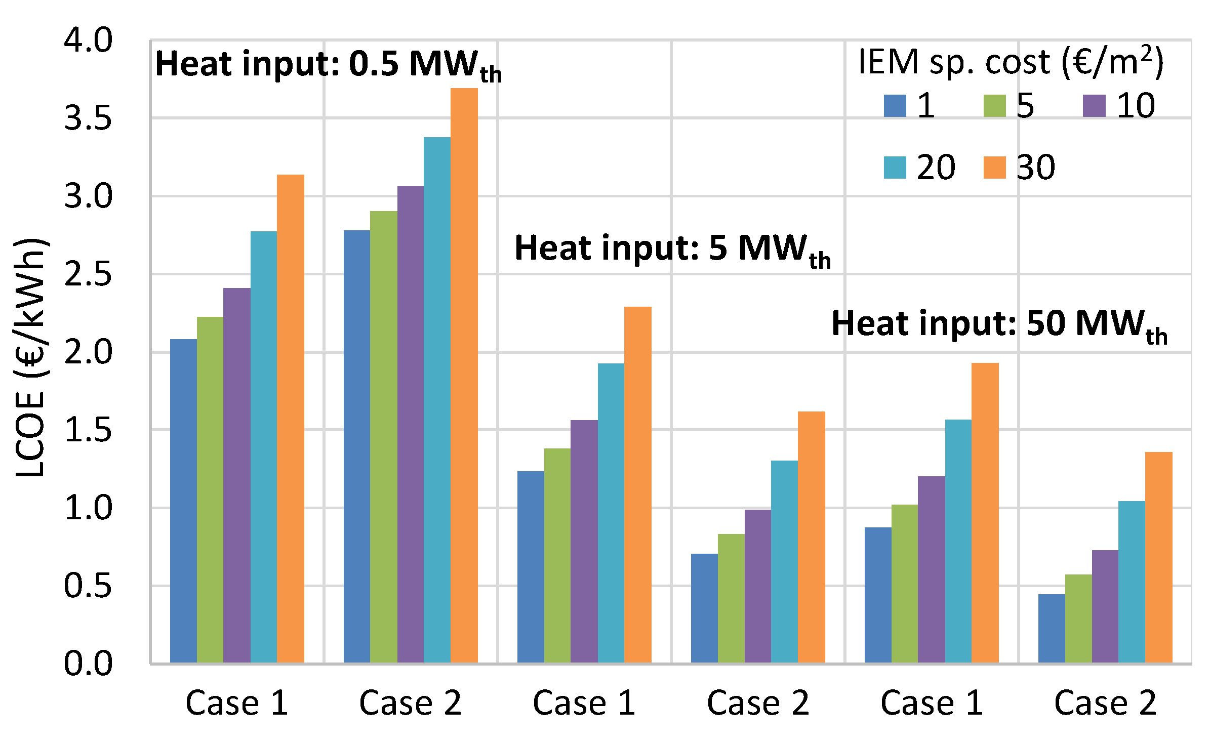
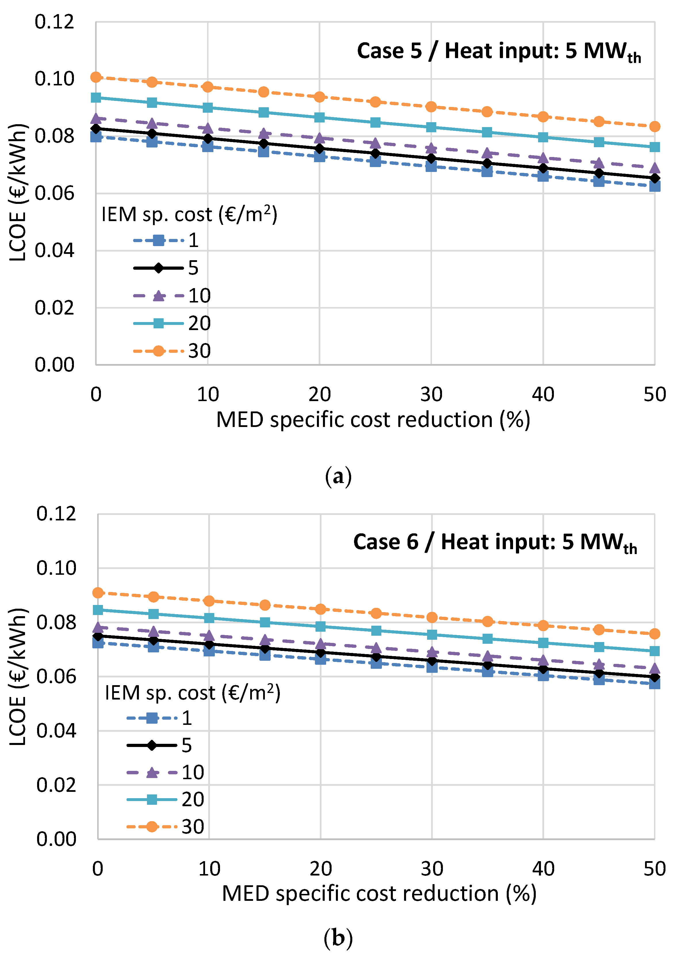
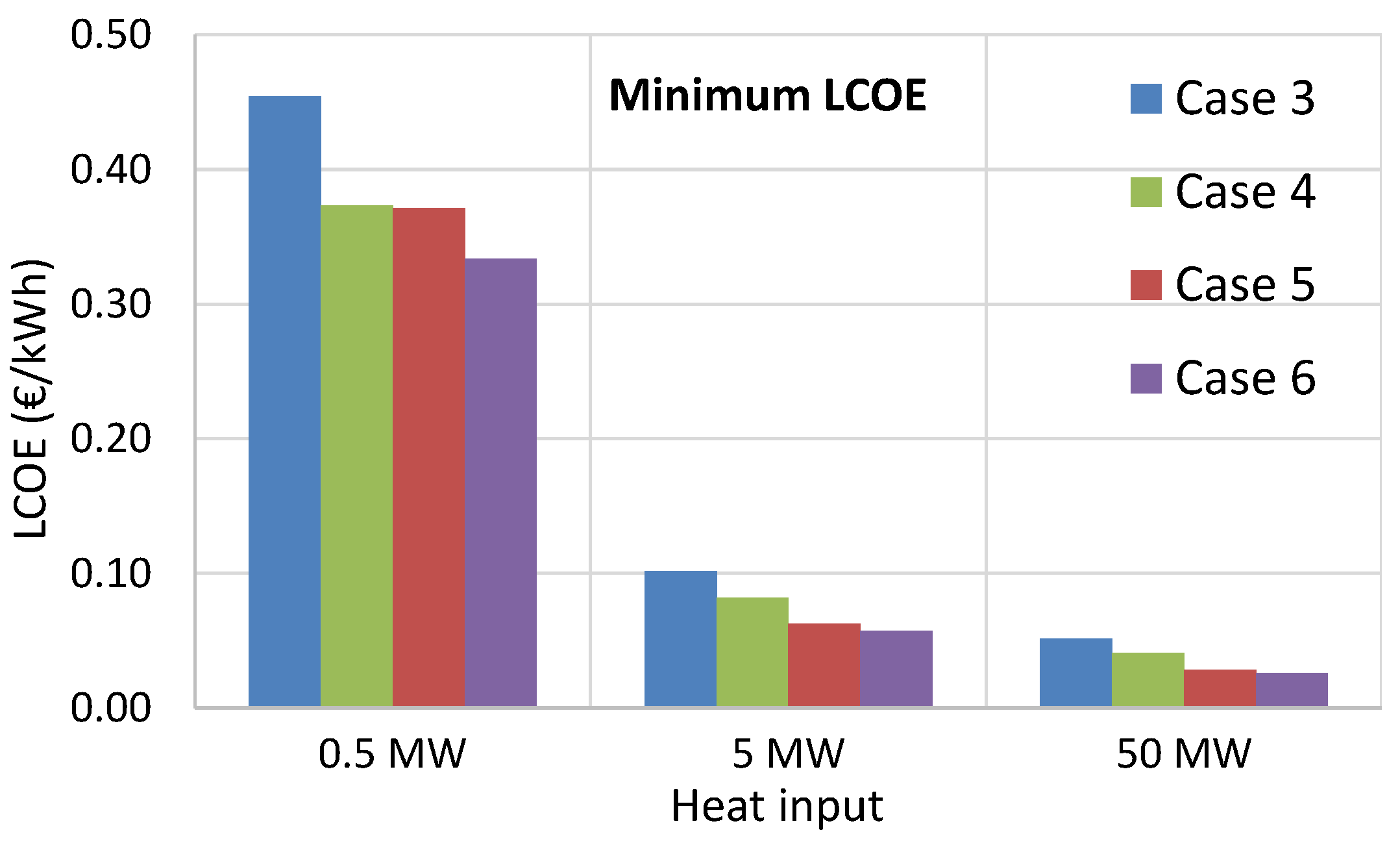
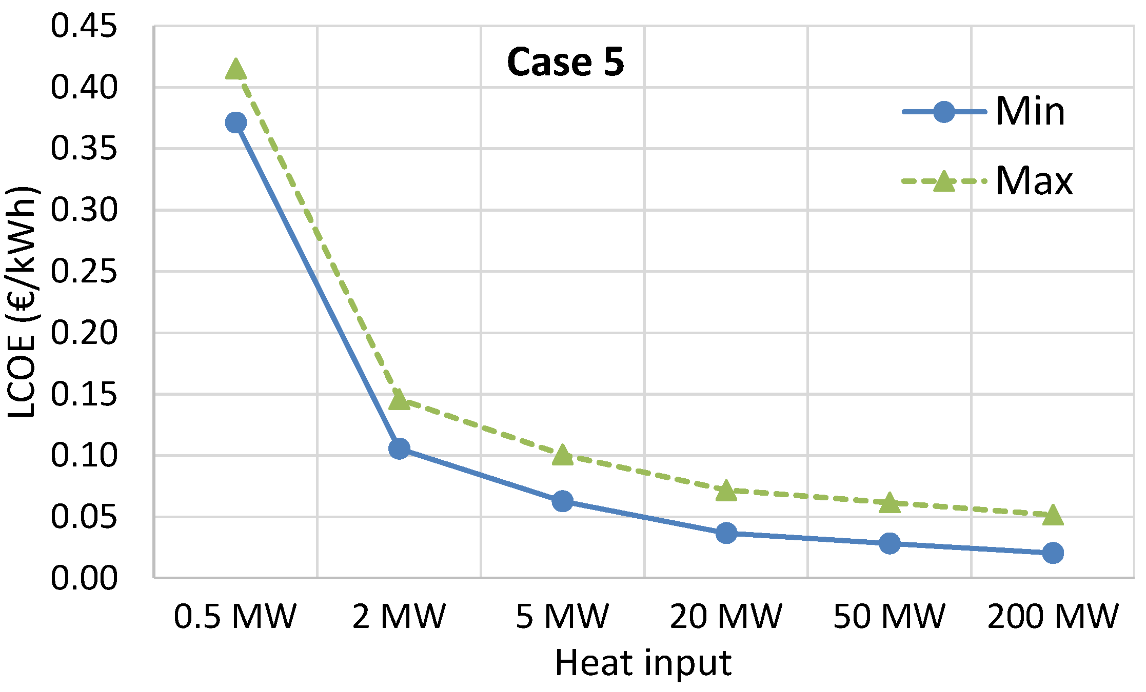
The economic analysis showed that the RED-MED system can become a promising and cost-competitive heat-to-power technology (reaching a LCOE of 0.06 €/kWh) for exploiting low-temperature waste heat when using high-performing IEMs, indicating that research in improving their performance should be a priority. When taking into account possible future reduction of the specific costs of the IEMs and MED equipment, while using preferably the KAc salt instead of NaCl, the resulting LCOE can be as low as 0.03 €/kWh for large-scale systems. However, there are many other cases that could offer very low LCOE values in the range of 0.04–0.10 €/kWh, even for medium-scale systems with a heat input of 5 MW, and without relying on drastic cost reductions of the RED and MED components. For small-scale systems with a heat input of 0.5 MW, the LCOE is much higher (the lowest possible value in the most optimistic scenario is 0.33 €/kWh), due to the high specific capital cost of the MED. The best performing case has been identified (case 5) that uses a low number of MED effects to reduce the specific cost of the regeneration process, while the use of KAc instead of NaCl has positive effects on both the performance and the cost. Finally, the reheating option to a reasonable temperature of 50 °C is necessary to improve the cost-effectiveness without imposing too much thermal stress on the membranes.
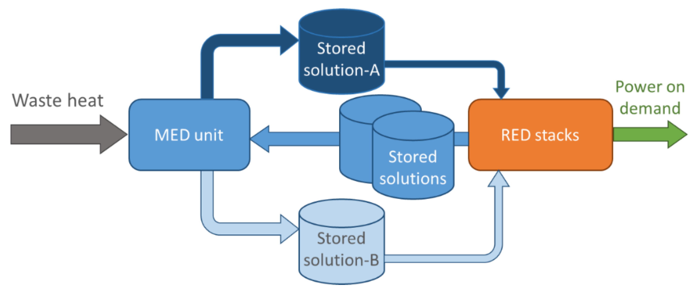
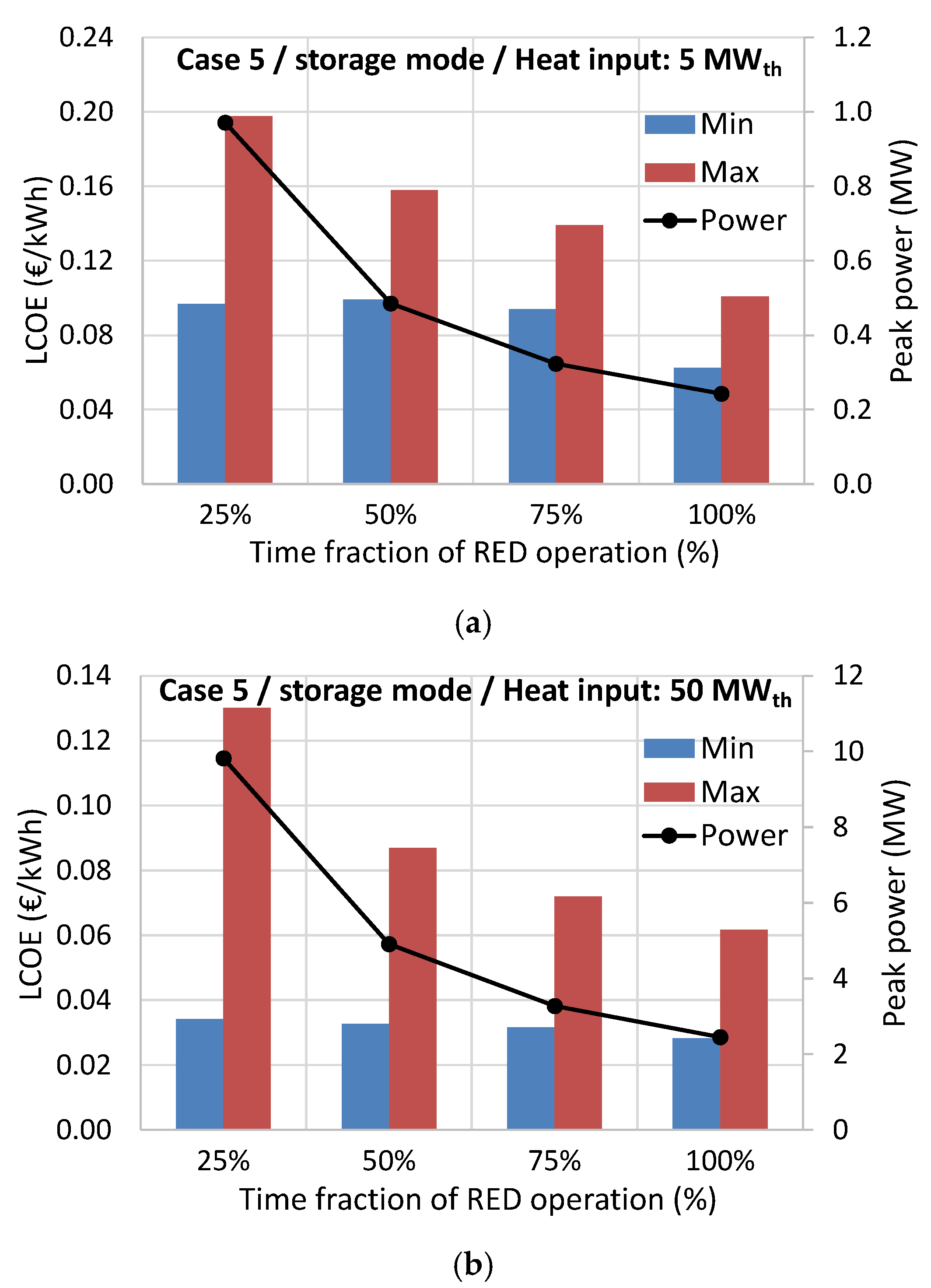
This best-performing case was then examined in storage mode, where the MED unit operates continuously to regenerate two solutions which are then stored in large reservoir tanks. A parameter that expresses the time fraction that the RED operates has been introduced, showing that the resulting LCOE increases for higher peak power production, but it can be kept below 0.10 €/kWh for large systems, even without relying on important future cost reductions of the RED and MED components, thus offering significant opportunities to industrial unit operators for peak power management and shifting.
The conclusions of the life-cycle environmental analysis point to the same solution (case 5), since the lower number of MED effects reduces the amount of metals used in the construction, which are the materials responsible for most of the environmental impacts.
The overall conclusion of the RED-MED system in both continuous and storage modes is that it can be more cost-competitive than other membrane-based heat engines, as well as to standard ORC technology. Also, the environmental impacts of the RED-MED system are low; lower than most other sustainable energy technologies and similar to ORC systems. In order to exploit this potential and to bring the RED-MED system closer to the market, the membranes’ performance would need to approach the performance of the high-performing membranes, preferably accompanied by a cost reduction, which is a direct effect of the economy of scale and large-scale market uptake.

Author Contributions

M.P.: cost analysis, LCA, paper writing; G.K.: cost analysis, paper writing; F.G. and B.O.-D.: RED-MED performance simulations, input of performance parameters, paper review; A.C. and A.T.: supervision and paper review; G.M.: final paper review.

Funding

This work has been performed within the RED-Heat-to-Power project (Conversion of Low Grade Heat to Power through closed loop Reverse Electro-Dialysis) - Horizon 2020 programme, Grant Agreement nr. 640667.

Conflicts of Interest

The authors declare no conflict of interest.

Appendix A. Life Cycle Inventory Analysis

The model assumes that there is one RED stack available. Each membrane has a surface of 0.25 m2 and the stack consists of 1000 cell pairs. The size of the RED is kept constant between all the cases and within the sensitivity analysis. The amount of heat and the size of the regeneration system change between cases to adapt to the performance of the system, thus making full use of the specific stack that was considered. For that reason, the amount of material associated with a RED stack is constant and provided in Table A1. This is the bill of materials for one stack, based on the available stack design during the implementation of this work. However, there is continuous progress in improving the industrial design, resulting in significant weight reduction and thus impact decrease.
Table A1. Materials associated with a RED stack.
MaterialsAmount
Stainless steel for the RED system7.20 kg
Steel for housing the RED system200.00 kg
Poly(diallyldimethylammonium chloride) for CEM8.75 kg
Polyethylene as support for the CEM and the AEM7.50 kg
Polystyrene sulphonated for the AEM8.75 kg
Electricity to produce the membranes of one stack45.00 kWh
PVC in the RED stack142.01 kg
Silicone in the RED stack2.00 kg
Pipes for the heat engine0.81 kg
Table A2 gives the calculated amount of the materials of the MED unit, which vary between the different design options.
Table A2. Materials associated with the MED unit.
MaterialsAmount (kg)
Case 1Case 2Case 3Case 4Case 5Case 6
Copper in the HEXs of the MED140525129829210301144
Nickel in the HEXs of the MED15627.933.232.4114.5127.1
Steel for housing the MED unit23441.949.848.6171.7190.6
Finally, based on all input data, the results of the model include: the total material used over the lifetime of the system, the total electricity produced, the resources used within the system, and the materials that go to waste.

Appendix B. Full Results of the LCA

The detailed results of the LCA for the six different cases are presented in Table A3, showing the contribution of each material and process to the total of the impact categories. The units used in all tables of this appendix are provided below:
  • GWP potential: kg CO2 eq.
  • Eutrophication Potential: kg Phosphate eq.
  • Acidification Potential: kg SO2 eq.
  • Terrestric Ecotoxicity Potential: kg DCB eq.
  • Ozone Layer Depletion Potential: kg R11 eq.
Table A3. Full results of the LCA for cases 1–6.
Case 1
Categorykg/MWhcoppernickelsteelplastictransportend-of-lifeother
GWP potential7.66 × 10+137.80%34.81%22.55%1.41%1.24%0.51%1.68%
Eutrophication Potential2.66 × 10−227.44%49.77%14.50%0.81%3.87%1.04%2.57%
Acidification Potential1.647.14%89.63%2.48%0.11%0.25%0.07%0.33%
Terrestric Ecotoxicity Potential4.0385.87%12.67%0.45%0.74%0.06%0.11%0.09%
Ozone Layer Depletion Potential2.22 × 10−6100.00%0.00%0.00%0.00%0.00%0.00%0.00%
Case 2
Categorykg/MWhcoppernickelsteelplastictransportend-of-lifeother
GWP potential1.94 × 10+122.99%21.17%43.50%7.23%0.95%1.10%3.05%
Eutrophication Potential6.10 × 10−318.39%33.35%31.25%4.62%3.34%3.16%5.89%
Acidification Potential2.73 × 10−16.62%83.17%7.55%0.85%0.30%0.22%1.29%
Terrestric Ecotoxicity Potential6.54 × 10−181.40%12.01%1.47%3.95%0.12%0.40%0.65%
Ozone Layer Depletion Potential3.42 × 10−7100.00%0.00%0.00%0.00%0.00%0.00%0.00%
Case 3
Categorykg/MWhcoppernickelsteelplastictransportend-of-lifeother
GWP potential2.9825.00%22.91%40.72%6.56%1.07%1.02%2.71%
Eutrophication Potential9.50 × 10−419.64%35.63%28.92%4.15%3.41%2.86%5.37%
Acidification Potential4.47 × 10−26.72%84.35%6.62%0.72%0.29%0.19%1.11%
Terrestric Ecotoxicity Potential1.08 × 10−182.23%12.14%1.28%3.35%0.11%0.34%0.55%
Ozone Layer Depletion Potential5.69 × 10−8100.00%0.00%0.00%0.00%0.00%0.00%0.00%
Case 4
Categorykg/MWhcoppernickelsteelplastictransportend-of-lifeother
GWP potential2.4024.40%22.47%41.50%6.75%0.98%1.04%2.85%
Eutrophication Potential7.62 × 10−419.33%35.06%29.51%4.27%3.40%2.94%5.51%
Acidification Potential3.54 × 10−26.70%84.06%6.85%0.75%0.30%0.19%1.15%
Terrestric Ecotoxicity Potential8.53 × 10−282.03%12.11%1.33%3.50%0.11%0.36%0.57%
Ozone Layer Depletion Potential4.49 × 10−8100.00%0.00%0.00%0.00%0.00%0.00%0.00%
Case 5
Categorykg/MWhcoppernickelsteelplastictransportend-of-lifeother
GWP potential1.1335.76%32.94%25.43%2.83%1.20%0.59%1.25%
Eutrophication Potential3.88 × 10−426.29%47.70%16.62%1.66%3.81%1.30%2.62%
Acidification Potential2.32 × 10−27.09%89.02%2.96%0.23%0.25%0.08%0.37%
Terrestric Ecotoxicity Potential5.67 × 10−285.45%12.61%0.55%1.04%0.07%0.14%0.14%
Ozone Layer Depletion Potential3.11 × 10−8100.00%0.00%0.00%0.00%0.00%0.00%0.00%
Case 6
Categorykg/MWhcoppernickelsteelplastictransportend-of-lifeother
GWP potential1.1436.74%33.84%24.04%2.49%1.22%0.56%1.11%
Eutrophication Potential3.92 × 10−426.85%48.71%15.59%1.45%3.84%1.17%2.39%
Acidification Potential2.38 × 10−27.11%89.32%2.72%0.20%0.25%0.07%0.32%
Terrestric Ecotoxicity Potential5.83 × 10−285.66%12.64%0.50%0.89%0.07%0.12%0.11%
Ozone Layer Depletion Potential3.21 × 10−8100.00%0.00%0.00%0.00%0.00%0.00%0.00%

References

  1. Papapetrou, M.; Kosmadakis, G.; Cipollina, A.; La Commare, U.; Micale, G. Industrial waste heat: Estimation of the technically available resource in the EU per industrial sector, temperature level and country. Appl. Therm. Eng. 2018, 138, 207–216. [Google Scholar] [CrossRef]
  2. Quoilin, S.; Declaye, S.; Tchanche, B.F.; Lemort, V. Thermo-economic optimization of waste heat recovery Organic Rankine Cycles. Appl. Therm. Eng. 2011, 31, 2885–2893. [Google Scholar] [CrossRef] [Green Version]
  3. Kosmadakis, G. Estimating the potential of industrial (high-temperature) heat pumps for exploiting waste heat in EU industries. Appl. Therm. Eng. 2019, 156, 287–298. [Google Scholar] [CrossRef]
  4. Toselli, D.; Heberle, F.; Brüggemann, D. Techno-Economic Analysis of Hybrid Binary Cycles with Geothermal Energy and Biogas Waste Heat Recovery. Energies 2019, 12, 1969. [Google Scholar] [CrossRef]
  5. Staub, S.; Bazan, P.; Braimakis, K.; Müller, D.; Regensburger, C.; Scharrer, D.; Schmitt, B.; Steger, D.; German, R.; Karellas, S. Reversible Heat Pump—Organic Rankine Cycle Systems for the Storage of Renewable Electricity. Energies 2018, 11, 1352. [Google Scholar] [CrossRef]
  6. Lecompte, S.; Huisseune, H.; Van Den Broek, M.; Vanslambrouck, B.; De Paepe, M. Review of organic Rankine cycle (ORC) architectures for waste heat recovery. Renew. Sustain. Energy Rev. 2015, 47, 448–461. [Google Scholar] [CrossRef]
  7. Tamburini, A.; Cipollina, A.; Papapetrou, M.; Piacentino, A.; Micale, G. Salinity Gradient Engines. In Sustainable Energy from Salinity Gradients; Woodhead Publishing: Cambridge, UK, 2016. [Google Scholar]
  8. Daniilidis, A.; Vermaas, D.A.; Herber, R.; Nijmeijer, K. Experimentally obtainable energy from mixing river water, seawater or brines with reverse electrodialysis. Renew. Energy 2014, 64, 123–131. [Google Scholar] [CrossRef]
  9. Giacalone, F.; Papapetrou, M.; Kosmadakis, G.; Tamburini, A.; Micale, G.; Cipollina, A. Application of reverse electrodialysis to site-specific types of saline solutions: A techno-economic assessment. Energy 2019, 181, 532–547. [Google Scholar] [CrossRef]
  10. Tedesco, M.; Cipollina, A.; Tamburini, A.; Micale, G.; Helsen, J.; Papapetrou, M. REAPower: Use of desalination brine for power production through reverse electrodialysis. Desalin. Water Treat. 2014, 53, 3161–3169. [Google Scholar] [CrossRef]
  11. Logan, B.E.; Elimelech, M.; States, U. Membrane-based processes for sustainable power generation using water. Nature 2012, 488, 313–319. [Google Scholar] [CrossRef] [PubMed]
  12. Tamburini, A.; Tedesco, M.; Cipollina, A.; Micale, G.; Ciofalo, M.; Papapetrou, M.; Van Baak, W.; Piacentino, A. Reverse electrodialysis heat engine for sustainable power production. Appl. Energy 2017, 206, 1334–1353. [Google Scholar] [CrossRef]
  13. Sen, P.K.; Sen, P.V.; Mudgal, A.; Singh, S.N.; Vyas, S.K.; Davies, P. A small scale Multi-effect Distillation (MED) unit for rural micro enterprises: Part I—design and fabrication. Desalination 2011, 279, 15–26. [Google Scholar] [CrossRef]
  14. Kosmadakis, G.; Papapetrou, M.; Ortega-Delgado, B.; Cipollina, A.; Alarcón-Padilla, D.C. Correlations for estimating the specific capital cost of multi-effect distillation plants considering the main design trends and operating conditions. Desalination 2018, 447, 74–83. [Google Scholar] [CrossRef]
  15. Giacalone, F.; Vassallo, F.; Griffin, L.; Ferrari, M.C.; Micale, G.; Scargiali, F.; Tamburini, A.; Cipollina, A. Thermolytic reverse electrodialysis heat engine: Model development, integration and performance analysis. Energy Convers. Manag. 2019, 189, 1–13. [Google Scholar] [CrossRef]
  16. Micari, M.; Cipollina, A.; Giacalone, F.; Kosmadakis, G.; Papapetrou, M.; Zaragoza, G.; Micale, G.; Tamburini, A. Towards the first proof of the concept of a Reverse ElectroDialysis-Membrane Distillation Heat Engine. Desalination 2019, 453, 77–88. [Google Scholar] [CrossRef]
  17. Bevacqua, M.; Tamburini, A.; Papapetrou, M.; Cipollina, A.; Micale, G.; Piacentino, A. Reverse electrodialysis with NH4HCO3-water systems for heat-to-power conversion. Energy 2017, 137, 1293–1307. [Google Scholar] [CrossRef]
  18. Ortega-Delgado, B.; Giacalone, F.; Catrini, P.; Cipollina, A.; Piacentino, A.; Tamburini, A.; Micale, G. Reverse electrodialysis heat engine with multi-effect distillation: Exergy analysis and perspectives. Energy Convers. Manag. 2019, 194, 140–159. [Google Scholar] [CrossRef]
  19. Palenzuela, P.; Micari, M.; Ortega-Delgado, B.; Giacalone, F.; Zaragoza, G.; Alarcón-Padilla, D.C.; Cipollina, A.; Tamburini, A.; Micale, G. Performance Analysis of a RED-MED Salinity Gradient Heat Engine. Energies 2018, 11, 3385. [Google Scholar] [CrossRef]
  20. Giacalone, F.; Olkis, C.; Santori, G.; Cipollina, A.; Brandani, S.; Micale, G. Novel solutions for closed-loop reverse electrodialysis: Thermodynamic characterisation and perspective analysis. Energy 2019, 166, 674–689. [Google Scholar] [CrossRef]
  21. Ortega-Delgado, B.; Giacalone, F.; Cipollina, A.; Papapetrou, M.; Kosmadakis, G.; Tamburini, A.; Micale, G. Boosting the performance of a Reverse Electrodialysis—Multi-Effect Distillation Heat Engine by novel solutions and operating conditions. Appl. Energy 2019, 253, 113489. [Google Scholar] [CrossRef]
  22. Daniilidis, A.; Herber, R.; Vermaas, D.A. Upscale potential and financial feasibility of a reverse electrodialysis power plant. Appl. Energy 2014, 119, 257–265. [Google Scholar] [CrossRef]
  23. Hu, J.; Xu, S.; Wu, X.; Wu, D.; Jin, D.; Wang, P.; Leng, Q. Theoretical simulation and evaluation for the performance of the hybrid multi-effect distillation—reverse electrodialysis power generation system. Desalination 2018, 443, 172–183. [Google Scholar] [CrossRef]
  24. Scientific Applications International Corporation (SAIC). Life Cycle Assessment: Principles and Practice; National Risk Management Research Laboratory, Office of Research and Development, US Environmental Protection Agency: Cincinnati, OH, USA, 2006.
  25. Liu, C.; He, C.; Gao, H.; Xie, H.; Li, Y.; Wu, S.; Xu, J. The environmental impact of organic Rankine cycle for waste heat recovery through life-cycle assessment. Energy 2013, 56, 144–154. [Google Scholar] [CrossRef]
  26. Uusitalo, A.; Uusitalo, V.; Grönman, A.; Luoranen, M.; Jaatinen-Värri, A. Greenhouse gas reduction potential by producing electricity from biogas engine waste heat using organic Rankine cycle. J. Clean. Prod. 2016, 127, 399–405. [Google Scholar] [CrossRef]
  27. Papapetrou, M.; Kumpavat, K. Environmental aspects and economics of salinity gradient power (SGP) processes. In Sustainable Energy from Salinity Gradients; Elsevier: Amsterdam, The Netherlands, 2016; pp. 315–335. [Google Scholar]
  28. Hickenbottom, K.L.; Miller-Robbie, L.; Vanneste, J.; Marr, J.M.; Heeley, M.B.; Cath, T.Y. Comparative life-cycle assessment of a novel osmotic heat engine and an organic Rankine cycle for energy production from low-grade heat. J. Clean. Prod. 2018, 191, 490–501. [Google Scholar] [CrossRef]
  29. Kosmadakis, G.; Landelle, A.; Lazova, M.; Manolakos, D.; Kaya, A.; Huisseune, H.; Karavas, C.S.; Tauveron, N.; Revellin, R.; Haberschill, P.; et al. Experimental testing of a low-temperature organic Rankine cycle (ORC) engine coupled with concentrating PV/thermal collectors: Laboratory and field tests. Energy 2016, 117, 222–236. [Google Scholar] [CrossRef] [Green Version]
  30. Guo, C.; Du, X.; Goswami, D.Y.; Yang, L. Investigation on working fluids selection for organic rankine cycles with low-temperature heat sources. Int. J. Green Energy 2016, 13, 556–565. [Google Scholar] [CrossRef]
  31. Imre, A.R.; Kustán, R.; Groniewsky, A. Thermodynamic Selection of the Optimal Working Fluid for Organic Rankine Cycles. Energies 2019, 12, 2028. [Google Scholar] [CrossRef]
  32. Papapetrou, M.; Cipollina, A.; LaCommare, U.; Micale, G.; Zaragoza, G.; Kosmadakis, G. Assessment of methodologies and data used to calculate desalination costs. Desalination 2017, 419, 8–19. [Google Scholar] [CrossRef]
  33. Sommariva, C. Desalination and Advanced Water Treatment: Economics and Financing; Balaban Desalination Publications: Hopkinton, MA, USA, 2010; Volume 40. [Google Scholar]
  34. Glade, H.; Moses, D.; Orth, T. Polymer composite heat exchangers. In Innovative Heat Exchangers; Springer: Cham, Switzerland, 2017. [Google Scholar]
  35. US EIA. Capital Cost Estimates for Utility Scale Electricity Generating Plants; US Department of Energy, Energy Information Administration: Washington, DC, USA, 2016.
  36. Southon, M.; Krumdieck, S. Energy Return on Investment (EROI) for Distributed Power Generation from Low-Temperature Heat Sources Using the Organic Rankine Cycle. In Proceedings of the 35th New Zealand Geothermal Workshop, Rotorua, New Zealand, 17–20 November 2013. [Google Scholar]
  37. Energy Information Administration. Updated Capital Cost Estimates for Electricity Generation Plants; U.S. Energy Information Administration: Washington, DC, USA, 2010.
  38. Government of Newfoundland & Labrador Department of Environment and Conservation Water Resources Management Division. Evaluation of Potable Water Storage Tanks in Newfoundland and Labrador and their Effect on Drinking Water; Government of Newfoundland & Labrador Department of Environment and Conservation Water Resources Management Division: St. John’s, NL, Canada, 2011.
  39. International Organization for Standardization. Environmental Management—Life Cycle Assessment—Requirements and Guidelines ISO14044; ISO: Geneva, Switzerland, 2006. [Google Scholar]
  40. Gerber, L.; Gassner, M.; Maréchal, F. Systematic integration of LCA in process systems design: Application to combined fuel and electricity production from lignocellulosic biomass. Comput. Chem. Eng. 2011, 35, 1265–1280. [Google Scholar] [CrossRef] [Green Version]
  41. Thinkstep AG. GaBi Software System and Database for Life Cycle Engineering; Thinkstep AG: Stuttgart, Germany, 2018. [Google Scholar]
  42. Turconi, R.; Boldrin, A.; Astrup, T. Life cycle assessment (LCA) of electricity generation technologies: Overview, comparability and limitations. Renew. Sustain. Energy Rev. 2013, 28, 555–565. [Google Scholar] [CrossRef] [Green Version]
  43. Raluy, G.; Serra, L.; Uche, J. Life cycle assessment of MSF, MED and RO desalination technologies. Energy 2006, 31, 2361–2372. [Google Scholar] [CrossRef]
  44. Palanov, N. Life-Cycle Assessment of Photovaltaic Systems—Analysis of Environmental Impact from the Production of PV System Including Solar Panels Produced by Gaia Solar. Master’s Thesis, Lund University, Lund, Sweden, 2014. [Google Scholar]
  45. Braimakis, K.; Karellas, S. Integrated thermoeconomic optimization of standard and regenerative ORC for different heat source types and capacities. Energy 2017, 121, 570–598. [Google Scholar] [CrossRef]
  46. Hickenbottom, K.L.; Vanneste, J.; Miller-Robbie, L.; Deshmukh, A.; Elimelech, M.; Heeley, M.B.; Cath, T.Y. Techno-economic assessment of a closed-loop osmotic heat engine. J. Memb. Sci. 2017, 535, 178–187. [Google Scholar] [CrossRef]
  47. Kheiri, A.; Feidt, M.; Pelloux-Prayer, S. Thermodynamic and economic optimizations of a waste heat to power plant driven by a subcritical ORC (Organic Rankine Cycle) using pure or zeotropic working fluid. Energy 2014, 78, 622–638. [Google Scholar]
  48. Walraven, D.; Laenen, B.; D’haeseleer, W. Minimizing the levelized cost of electricity production from low-temperature geothermal heat sources with ORCs: Water or air cooled? Appl. Energy 2015, 142, 144–153. [Google Scholar] [CrossRef] [Green Version]
  49. Papapetrou, M.; Kosmadakis, G.; Frías, P.; Gómez, T.; Simons, L. Evaluating the Factors Affecting the Break-Even Cost of On-Site PV Generation at Industrial Units. In Proceedings of the 33 European Photovoltaic Solar Energy Conference and Exhibition (EU PVSEC), Amsterdam, The Netherlands, 25–29 September 2017. [Google Scholar]
  50. Bai, L. Life Cycle Assessment of Electricity Generation from Low Temperature Waste Heat. Master’s Thesis, Norwegian University of Science and Technology, Trondheim, Norway, 2012. [Google Scholar]
Figure 1. Depiction of the RED-MED system in storage mode showing the reservoir tanks.
Energies 12 03206 g001
Figure 2. Storage (reservoir) tank specific cost as a function of its storage capacity.
Energies 12 03206 g002
Figure 3. LCOE of the two configurations with reference membranes (cases 1-2) for variable heat input as a function of the IEM specific cost.
Energies 12 03206 g003
Figure 4. LCOE of the two configurations with reference membranes (cases 1–2) for variable heat input as a function of the MED cost reduction.
Energies 12 03206 g004
Figure 5. LCOE of the configurations with high-performing membranes (cases 3–4) as a function of the IEM specific cost and MED cost reduction for heat input of 5 MWth. (a) Case 3, (b) Case 4.
Energies 12 03206 g005
Figure 6. LCOE of the configurations with high-performing membranes including reheating (cases 5–6) as a function of the IEM specific cost and MED cost reduction for heat input of 5 MWth. (a) Case 5, (b) Case 6.
Energies 12 03206 g006
Figure 7. LCOE range of the four configurations with high-performing membranes (cases 3–6) for variable heat input.
Energies 12 03206 g007
Figure 8. LCOE range of case 5 for variable heat input as a function of the IEM specific cost and MED cost reduction for various system scales.
Energies 12 03206 g008
Figure 9. LCOE of case 5 with higher numbers of MED effects for variable heat input.
Energies 12 03206 g009
Figure 10. LCOE of case 5 in storage mode as a function of the time fraction that RED operates for a medium and large-scale system. (a) Medium-scale system, (b) Large-scale system.
Energies 12 03206 g010
Figure 11. Relative contribution of materials to the calculated impacts of case 5.
Energies 12 03206 g011
Figure 12. Outcomes of the sensitivity analysis of case 5.
Energies 12 03206 g012
Table 1. Properties of the high-performing membranes.
PropertyValue
Electrical resistance, R a v (Ω·cm2)1/8 of reference value
Permselectivity, α a v (–)98%
Salt permeability, P s (m2/s)1/4 of reference value
Water permeability, P w (m/(Pa⋅s))1/4 of reference value
Table 2. Overview of the configurations considered.
ConfigurationIEM TypeMED EffectsSaltRED Solution Temperature (°C)
1Reference24NaCl25
2Reference6NaCl25
3High-performing6NaCl25
4High-performing6KAc25
5High-performing6KAc50
6High-performing6KAc80
Table 3. Performance parameters of all configurations/cases with one RED stack [21].
Configuration/CaseGross Power (kW)Pump Power, Total (kW)MED Specific HEX Surface (m2/kg/s)Heat Input (kW)Thermal Efficiency (%)
10.440.156703.931.70.90
20.440.112127.7107.10.31
32.460.126150.7108.02.16
42.920.096165.694.92.98
514.590.310182.6290.54.92
616.460.301178.9290.85.56
Table 4. Parameters of the cost analysis.
ParameterValue
Capacity factor90%
Plant lifetime (n)30 years
Discount rate (r)5%
IEMs lifetime10 years
IEM specific cost (variable)1–30 €/m2
MED specific cost reduction (variable)0–50%
Table 5. Net power production and number of RED stacks of all configurations for a heat input of 0.5, 5, and 50 MWth.
Heat Input:0.5 MWth5 MWth50 MWth0.5 MWth5 MWth50 MWth
CasesNet Power Production (kW)Number of RED Stacks
13.5735.23351.67161581577
21.6415.42153.18547467
311.67109.701080.64547463
414.12149.671485.42553526
528.56242.762456.16217172
632.32274.702779.35217172
Table 6. Capital cost break-down for all configurations (heat input of 5 MWth for a medium-scale system).
ConfigurationCapital Cost Contribution (%)
REDMEDOther
135.7164.170.13
249.1650.640.20
347.1851.451.37
449.7048.611.69
520.6173.695.70
620.5773.306.13
Table 7. LCOE of cases 1–2 with reference membranes for variable heat input.
Heat Input (MWth)LCOE (€/kWh)
Case 1Case 2
0.53.133.69
52.291.62
501.931.36
Table 8. Minimum LCOE of cases 1–2 with reference membranes for variable heat input (IEMs specific cost of 1 €/m2 and MED cost reduction of 50%).
Heat Input (MWth)Minimum LCOE (€/kWh)
Case 1Case 2
0.51.322.44
50.680.46
500.470.26
Table 9. LCOE of cases 3–6 with high performing membranes for variable heat input.
Heat Input (MWth)LCOE (€/kWh)
Case 3Case 4Case 5Case 6
0.50.630.520.420.37
50.270.220.100.09
500.210.170.060.06
Table 10. Main impact results for the different cases, referring to 1 kWh of net electricity production.
GWP Potential (g CO2 eq.)Eutrophication Potential (g Phosphate eq.)Acidification Potential (g SO2 eq.)
case 176.562.66 × 10−21.64
case 219.376.10 × 10−30.27
case 32.989.50 × 10−44.47 × 10⁻²
case 42.407.62 × 10−43.54 × 10⁻²
case 51.133.88 × 10−42.32 × 10⁻²
case 61.143.92 × 10−42.38 × 10⁻²
Table 11. Parameters of the sensitivity analysis of case 5.
Variable ExplanationLowBase CaseHigh
Capacity factor (%)60%90%100%
Frequency of IEM replacement (years)51015
Transport distance (km)1006001800
Table 12. Acidification and global warming impacts of sustainable energy technologies.
TechnologiesAcidification (g SO2 eq./kWh)Global Warming (g CO2 eq./kWh)Reference
RED HE (Case 1)1.64076.56Current work
Base case OHE0.29468.83[28]
RED HE (Case 2)0.27319.37Current work
Solar PV0.12–0.2913–190[42]
Wind0.02–0.093–41
RED HE (Case 3)0.0452.98Current work
RED HE (Case 4)0.0352.40Current work
Improved case OHE0.0298.64[28]
RED HE (Case 5)0.0231.13Current work
RED HE (Case 6)0.0241.14Current work
Hydropower0.001–0.032–20[42]
ORC0.015–0.0261.28–9.25[50]

