Comparison and Design of Resonant Network Considering the Characteristics of a Plasma Generator

1
Department of Electrical and Computer Engineering, Sungkyunkwan University, 2066, Seobu-ro, Jangan-gu, Suwon-si 16419, Gyeonggi-do, Korea
2
Automotive Research & Development Division, Hyundai Motor Group, 150, Hyundaiyeonguso-ro, Namyang-eup, Hwaseong-si 18280, Gyeonggi-do, Korea
*
Author to whom correspondence should be addressed.
Energies 2019, 12(16), 3156; https://doi.org/10.3390/en12163156
Submission received: 22 July 2019
/
Revised: 7 August 2019
/
Accepted: 15 August 2019
/
Published: 16 August 2019
(This article belongs to the Special Issue Smart Energy, Plasma and Nuclear Systems)
Abstract
:This paper presents a theoretical analysis and experimental study on the resonant network of the power conditioning system (PCS) for a plasma generator. In order to consider the characteristics of the plasma load, the resonant network of the DC-AC inverter is designed and analyzed. Specifically, the design of an LCL resonant network and an LCCL resonant network, which can satisfy the output current specification in consideration of plasma characteristics, is explained in detail. Moreover, the inverter current and phase angle between the inverter voltage and current is derived for evaluating inverter performance. Based on these analysis results, the DC-AC inverter can be designed for a plasma generator considering plasma load characteristics. The theoretical analysis of both networks is validated through the simulation and experimental results.
1. Introduction
Plasma generators are used in various industrial fields for display panels and in the wafer cleaning process of semiconductors. According to the growth in the display and semiconductor markets, plasma generators are becoming increasingly important in industrial fields [1,2]. These plasma generators are conventionally constructed as a power conditioning system (PCS) and a chamber for plasma generation. High frequency current must be supplied by the PCS to the reactor, which is a magnetic substance in the chamber for supply energy which is used to ionize the gas entering the chamber. The electric field for ionizing is generated according to the frequency, sinusoidal wave, and magnitude of the supplied current. Therefore, in order to effectively generate the electric field, the PCS should supply high switching frequency and low total harmonic distortion (THD) constant current [3,4].
Another characteristic of the PCS for a plasma generator is that the inverter of the PCS using zero voltage switching (ZVS) is conventionally adopted to decrease the switching losses. In order to implement ZVS, the phase shift technique or load resonant technique has been used in previous research on the inverter. In order to achieve ZVS, the inverter should be designed in consideration of the following load characteristics in the plasma load case [5]: (1) the resistance of the load is increased in proportion to the gas injected into the chamber; (2) the resistance of the load is changed in inverse proportion to the load current [6]; (3) a constant load current is recommended for maintaining the stable plasma state; (4) the THD of the load current should be low for effective plasma generation [7,8,9].
In the case of the conventional resistive load, the pulse frequency modulation (PFM) or phase shift control are applied for the ZVS operation of the inverter. In plasma load, applying the PFM to the control output current is difficult due to the characteristics of the plasma load mentioned above. When the PFM is used to vary the output current in the plasma load, the plasma load resistance is varied depending on the output current. If the output current for generating plasma is increased, the resistance of the plasma load is decreased. When the output current for generating plasma is decreased, the resistance of the plasma load is decreased in an inversely proportional manner [6]. In addition, the designed initial Q-factor is varied rapidly due to changes in resistance. Because of the changed Q-factor, the resonant inverter cannot control the output current to the designed value.
Therefore, regulating the inverter output current using PFM is difficult because the plasma load resistance is changed again and the phenomena mentioned previously occur repeatedly. In order to solve these problems, the phase shift control should be used for the output current regulation. Conventionally, the phase shift full bridge inverter and load resonant inverter can solve the problem of using the phase shift control. In the plasma load case, the harmonics of the output current should be strictly regulated in order to satisfy plasma quality as characteristics of the plasma load [10,11,12,13]. Hence, it is difficult to adopt a phase shift full bridge inverter for the plasma system, and only the load resonant inverter using the phase shift method can be adopted. If a phase shift inverter is used for the plasma load, the filter with the ability to implement the sinewave of the load current is required for designing a phase shift inverter [14,15]. Using the additional filter on the phase shift inverter leads to increased system cost and volume. For this reason, the load resonant inverter using phase shift control is preferred for the plasma load system over the phase shift inverter with an additional filter [15].
In order to adopt a load resonant inverter in the plasma system, the effective resonant network design should be considered. There are two representative resonant networks for plasma systems: the structure of an LCL resonant network and the structure of an LCCL resonant network. These networks have different characteristics of the maximum inductor current and phase angle between inverter voltage (vo.inv) and inverter current (io.inv). In the resonant network design, the maximum inductor current and inverter phase are the factors that influence the conduction loss and the soft-switching range for phase shift control. Therefore, in order to design a resonant network that is suitable for a plasma generator, the characteristics of the LCL network and the LCCL network should be compared to select the optimal maximum inductor current and phase angle.
In this paper, in order to explain the specialty of plasma load to the design of the resonant network, both the LCL network and LCCL network, which are conventionally used for resonant inverter systems and satisfy the specification of the plasma load, are analyzed in detail. Based on the analysis, the LCL resonant network and LCCL network are designed in consideration of the characteristics of the plasma load and with the aim of preventing the drop-out phenomenon. In order to evaluate the designed networks, simulation and analysis are conducted. Finally, the experimental results based on a 1 kW plasma generator are presented to verify the performances of the LCCL and LCL resonant networks on the plasma generator.
2. Control Scheme and Characteristics of the Plasma Load
Figure 1 shows the conceptual circuit diagram of the plasma generation system that generates plasma by injecting gas into the reactor of the chamber. In Figure 1, Lr, Cr, Llkg, and Rplasma represent the resonant inductor, resonant capacitor, leakage inductor, and the equivalent resistance of the plasma load, respectively. The “Vin” represents the input voltage of the inverter. vo.inv, io.inv, and iplasma indicate the mean output voltage of the inverter, the output current of the inverter and the output current for generating plasma, respectively. In the plasma generation system, the injected gas affects the load. This plasma generator has unique features: (1) the impedance of the plasma load is proportionally decreased according to the increase in iplasma value [6] and (2) the sinusoidal wave is highly recommended for generating plasma [15]. These characteristics are an important consideration point for designing the power supply of the plasma system.
2.1. Chracteristics Analysis of the Plasma Load
These characteristics cause a special issue in the plasma system. Among the above-mentioned plasma characteristics, the impedance of plasma load leads to a special issue when pulse frequency modulation is adopted for output current control. In Figure 2, in order to regulate the output current, the switching frequency (fsw) is changed to be above resonant frequency (fr). In the conventional gain curve of the resonant network shown in Figure 2, in order to regulate the output current, increasing or decreasing switching frequency is normally used in the resistive load.
However, in the plasma load case, when increasing the switching frequency to reduce the output current the plasma load impedance is increased according to the reduced output current. The increased impedance changes the Q-factor of the network to make a sharp current gain curve. In addition, the output current is decreased again because of the change in the current output gain curve, as shown in Figure 2. These mechanisms progress repeatedly until the output current reaches zero. Therefore, using PFM to control the output current is difficult in the plasma load. This phenomenon is called drop-out and is observed when controlling output current using PFM in the plasma load. In order to solve the above-mentioned problems, the phase shift control scheme should be adopted for the resonant inverter to satisfy the output current control range. Moreover, the inverter should be operated at the resonant frequency to avoid plasma drop-out.
2.2. Control Method Considering Characteristics of the Plasma Load
In order to obtain various output current ranges with ZVS, the resonant network should be designed to consider the minimum phase shift angle which can control the minimum plasma current with ZVS operation. The minimum phase shift angle is calculated by Equation (1) [14], which represents the relation between the amplitude of the fundamental wave of the inverter output voltage (vo.inv.1) and the phase shift angle.
Figure 3 shows the phase shift control scheme for output current control in the resonant inverter. In this scheme, the inverter is operated in order to reduce the fundamental wave of the inverter output voltage (vo.inv.1) with increasing phase shift angle for reducing the width of the square wave (β). In this control scheme, the vo.inv.1 can be calculated using Equation (1) and the phase angle between the inverter output voltage and output current is the crucial factor during ZVS to obtain various output currents. According to Equation (1), vo.inv.1 can be controlled to adjust the phase shift angle at the fixed resonant frequency. The output current is obtained by the relationship between vo.inv.1 calculated using Equation (1) and the designed resonant network gain. Therefore, the maximum inverter current and phase angle between vo.inv and io.inv should be considered in designing the resonant network to achieve lower conduction loss and soft-switching.
3. Analysis of the Resonant Network for the Plasma Load
The LCL network and the LCCL network are suitable structures for the resonant network for plasma generation. Depending on the network, the phase angle between the inverter maximum current and the plasma current has different characteristics. Therefore, impedance analysis is necessary for considering the different characteristics of the resonant network depending on variations in the values of passive elements. Using the results of impedance analysis, the maximum current of the inverter, plasma current at the resonant frequency, and the phase between the inverter voltage and the current can be calculated.
3.1. Analysis of LCL Resonant Network
The LC resonant network is suitable for satisfying the constant current output of the plasma inverter with just a few passive elements. However, the LC resonant network is constructed here as the LCL network because of the leakage inductance of the reactor which is used for plasma generation, as shown in Figure 4. Therefore, in order to design the power supply for the plasma generator, the characteristics of the LCL network should be analyzed mathematically. The first consideration point in designing the network using mathematical analysis is deriving the Lr and Cr values, which can regulate the constant output current of the inverter regardless of load variation.
In order to regulate the constant output current while preventing drop-out, the resonant frequency should be selected as an operating frequency of the inverter, and the output current can be derived from impedance analysis, as shown in Equation (2) [14]. Figure 5a presents the characteristics of output current through the impedance analysis according to frequency variation. As shown in Figure 5a, the output current changes with the load variation, except for the resonant frequency. Therefore, the resonant network should be designed to satisfy the maximum output current value at the resonant frequency in the plasma generation system.
After determining the maximum current, phase shift control is necessary for satisfying the minimum current of the load requirement and preventing drop-out. The phase shift angle for satisfying the minimum output current with phase shift control can be calculated using Equation (1). The consideration point for satisfying the phase shift angle which is calculated to regulate the minimum output current in the inverter is the phase difference between the inverter voltage and the current. When the phase difference is smaller than the phase shift angle, the inverter is operated in the hard-switching region. By contrast, when the phase difference is larger than phase shift angle, the inverter could be operated in the soft-switching region. The relationship between the phase shift angle and the phase difference is considered using Equation (3) [16]. If the calculation results of Equation (3) are larger than the required phase shift angle, the inverter could be operated in the soft-switching region at resonant frequency. Figure 5b shows the phase difference between the inverter voltage and the current according to load variation. When the inverter is operated at the resonant frequency to prevent drop-out and when the resistance of the load is small, the phase difference is large. Furthermore, the phase difference becomes small when the resistance of the load is large, as shown in Figure 5b.
Using the above-mentioned analysis, the inverter can control the output current, which is required for plasma generation. Regarding the other point of consideration aside from controlling load current in order to design the power supply for the plasma generator, the inverter current (io.inv) should be considered for the efficiency of the inverter. The inverter current, which is the main cause of inverter losses, can be calculated using Equation (4) [16]. This inverter current can be used for the index of the inverter efficiency. Therefore, in order to design a high efficiency inverter, the inverter current should be considered.
3.2. Analysis of LCCL Resonant Network
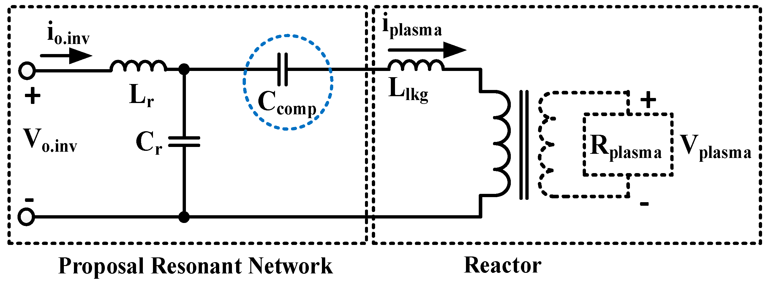
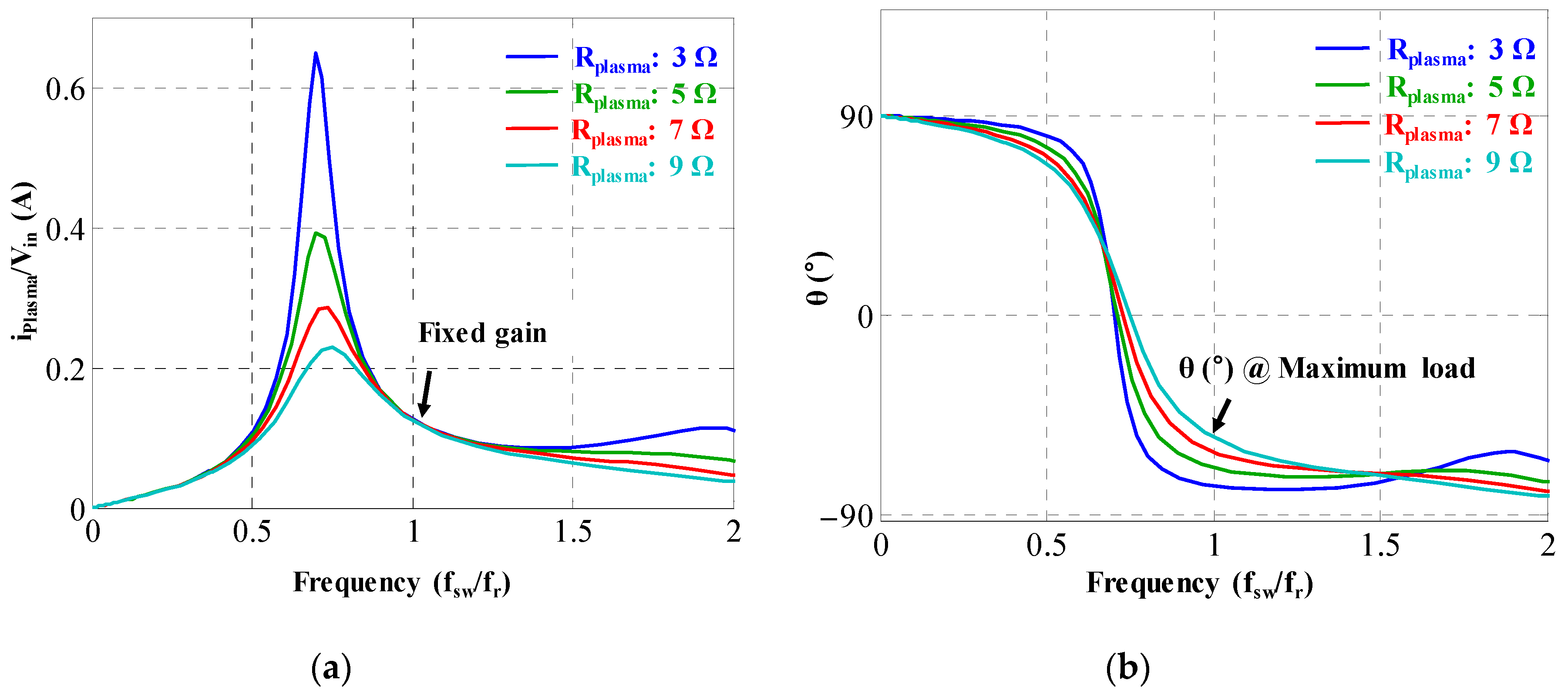
The other structure of the resonant network for applying the plasma inverter is the LCCL network, as shown in Figure 6. Using the LCCL network, it is possible to compensate for the phase difference, which is not possible with the LCL network. In the case of the LCCL network design, it is necessary to use impedance analysis, as shown in Equation (5), to regulate the constant output current regardless of the load at the resonant frequency in order to prevent drop-out. Figure 7a shows the maximum current of the LCCL network according to load variation. Aside from the resonant frequency, the output current is changed with the load variation, as shown in Figure 7a.
The phase shift control is also necessary for satisfying the minimum output current of the LCCL network. In this case, the phase shift angle satisfying the minimum output current can be calculated using Equation (1), and the phase shift angle is equal to the case of the LCL network case because both networks are designed for the same maximum current. In the case of the LCL network, designing the phase difference between the inverter voltage and current is difficult because the values of Lr, Cr, and Llkg are already fixed in order to satisfy the maximum output current. On the other hand, in the case of the LCCL network, the phase difference can be designed through the added compensation capacitor (Ccomp), as shown in Equation (6). Figure 7b shows the phase difference of the LCCL network according to the load variation at the resonant frequency. As shown in Figure 7b, the LCCL network can ensure a wider phase difference than the LCL network. Therefore, the LCCL network can be operated in a wider ZVS range than the LCL network. In the case of the LCCL network, the inverter current can be calculated using Equation (7), and the inverter current of the LCCL network is increased compared with the inverter current of the LCL network.
Because of the compensation capacitor (Ccomp), as mentioned previously, the inverter current of the LCCL network is higher than that of the LCL network, and the LCCL network can extend the ZVS region due to the compensation capacitor. Therefore, considering the overall efficiency of the inverter, loss analysis is necessary to compare the efficiency of both networks.
4. Simulation and Experimental Results
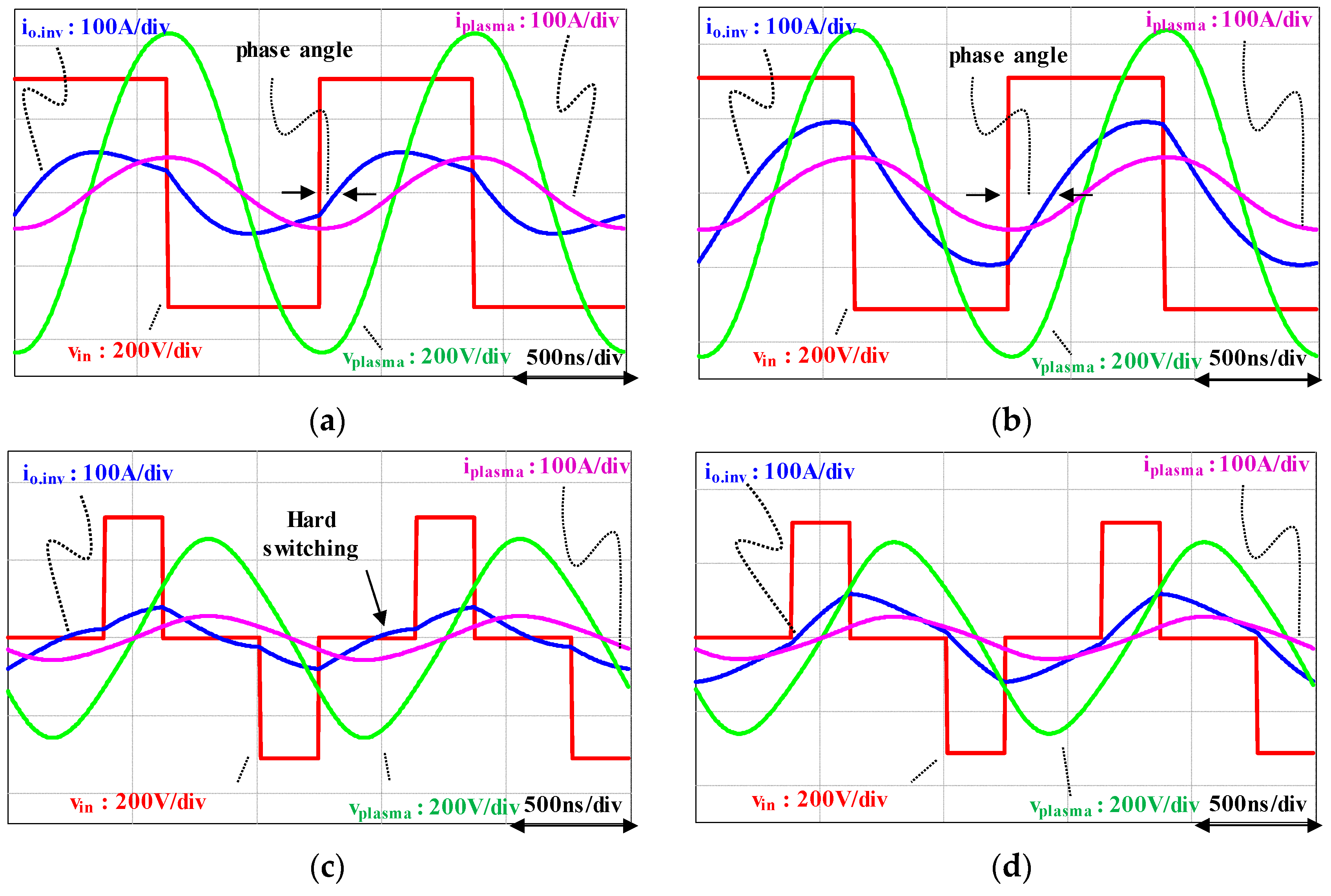
The simulation and experimental results are presented for the purpose of verifying the analysis of the resonant network. The simulation has been conducted to describe the operation characteristics regarding the requirement and the phase shift angle. Finally, the applicability of the LCCL resonant network for the plasma generator is validated using experimental results. Figure 8 shows the simulation waveform about the LCL network and the LCCL network in the maximum current output condition. Both of the resonant networks can be operated to satisfy the maximum current output as shown in Figure 8a,b. When the LCL network is operated under the minimum current output conditions, the hard-switching region appears as is shown in Figure 8c. On the other hand, as shown in Figure 8d, the LCCL network can be operated with ZVS under the minimum load condition.
Loss analysis has been conducted to compare the efficiency of each resonant network [17]. In order to analyze the losses of the inverter, only the switch loss is considered, without any loss of resonant inductor, which consists of an air core inductor and a resonant capacitor. Regarding the analysis results, the loss of the LCL network is smaller than that of the LCCL network in the ZVS operation region under the 20 A output condition, as shown in Figure 9. In the non-ZVS operation region at the 20 A output condition, the loss of the LCL network is larger than that of the LCCL network. Beyond the 25 A output region, the loss of the LCCL network is larger than that of the LCL network because the large inverter current is required in the LCCL network.
The experiment has been conducted based on the parameters listed in Table 1. Among these parameters, the input voltage 1/3 scale-down model has been used with consideration of the laboratory power distribution. The resonant network has been designed with Equation (2) considering switching frequency and maximum output current. Figure 10a shows the experimental waveform of the LCL network, which represents the narrow phase angle. In this case, it is impossible for iplasma to be controlled with the ZVS region using the phase shift control to obtain a minimum value, as shown in Figure 10a. On the other hand, a sufficient phase angle for the phase shift control in the ZVS region is obtained in the LCCL network, as shown in Figure 10b. In this result, the DC-AC inverter adopting the LCCL network can be operated with ZVS despite the worst case for obtaining the phase angle, as shown in Figure 10c.
The phase difference and soft-switching ability of the designed networks are verified through these experimental results. In the resonant inverter for using the plasma generator, the inverter loss is determined with the trade-off relationship between the conduction loss of the inverter current and the switching loss due to the phase difference. Therefore, the LCCL resonant network could be better performing than the LCL network under the large resistance of the plasma load and small plasma current conditions.
5. Conclusions
In this paper, the applicability of the LCL network and LCCL network for a plasma generator have been investigated with consideration of the characteristics of the plasma load. In particular, the drop-out phenomenon, which is substantially different from the resistive load, is considered for the design of an LCL network and an LCCL network. Considering the characteristics of the plasma load, an LCL network and an LCCL network are designed and analyzed. Based on the analysis, a simulation was conducted in order to verify the validity of the designed networks. Furthermore, the experiment was progressed while considering the laboratory power distribution level in order to verify the applicability of the networks.
Author Contributions
Conceptualization, G.W.K. and W.-Y.S.; methodology, G.W.K.; software, G.W.K. and W.-Y.S.; validation, G.W.K.; formal analysis, G.W.K.; investigation, G.W.K.; resources, B.K.L.; data curation, G.W.K.; writing—original draft preparation, G.W.K. and B.K.L.; writing—review and editing, G.W.K. and B.K.L.; visualization, G.W.K. and W.-Y.S.; supervision, B.K.L.; project administration, B.K.L.; funding acquisition, B.K.L.
Funding
This work was supported by “Human Resources Program in Energy Technology” of the Korea Institute of Energy Technology Evaluation and Planning (KETEP), granted financial resource from the Ministry of Trade, Industry & Energy, Korea. (No. 20184030202190); This work was supported by the Korea Institute of Energy.
Conflicts of Interest
The authors declare no conflict of interest.
References
- Shimizu, K.; Kinoshita, K.; Yanagihara, K.; Rajanikanth, B.S.; Katsura, S.; Mizuno, A. Pulsed-Plasma Treatment of Polluted Gas Using Wet-/Low-Temperature Corona Reactors. IEEE Trans. Ind. Appl. 1997, 33, 1373–1380. [Google Scholar] [CrossRef]
- Kim, D.W.; You, S.J.; Kim, J.H.; Chang, H.Y.; Oh, W.Y. Computational Characterization of a New Inductively Coupled Plasma Source for Application to Narrow Gap Plasma Processes. IEEE Trans. Plasma Sci. 2015, 43, 3876–3882. [Google Scholar] [CrossRef]
- Millner, A.R. Power Electronics Topologies for Plasma Generators. In Proceedings of the 2008 IEEE International Symposium on Industrial Electronics, Cambridge, UK, 30 June–2 July 2008; pp. 359–362. [Google Scholar]
- Tran, K.; Millner, A. A New Power Supply to Ignite and Sustain Plasma in a Reactive Gas Generator. In Proceedings of the 2008 Twenty-Third Annual IEEE Applied Power Electronics Conference and Exposition, Austin, TX, USA, 24–28 February 2008; pp. 1885–1892. [Google Scholar]
- Ahn, H.M.; Sung, W.-Y.; Lee, B.K. Analysis and Design of Resonant Inverter for Reactive Gas Generator Considering Characteristics of Plasma Load. J. Electro. Eng. Technol. 2018, 13, 345–351. [Google Scholar]
- Chabert, P.; Braithwaite, N. Impedance of the Plasma Alone. In Handbook of Semiconductor Wafer Cleaning Technology; Cambridge University Press: Cambridge, UK, 2011; pp. 233–235. [Google Scholar]
- Lee, S.Y.; Gho, J.-S.; Kang, B.-H.; Cho, J.-S. Analysis of Pulse Power Converter for Plasma Application. In Proceedings of the 2008 IEEE International Symposium on Industrial Electronics, Cambridge, UK, 30 June–2 July 2008; pp. 556–560. [Google Scholar]
- Kuroki, T.; Mine, J.; Okubo, M.; Yamamoto, T.; Saeki, N. CF4 Decomposition Using Inductively Coupled Plasma: Effect of Power Frequency. IEEE Trans. Ind. Appl. 2005, 41, 215–220. [Google Scholar] [CrossRef]
- Kuroki, T.; Mine, J.; Odahara, S.; Okubo, M.; Yamamoto, T.; Saeki, N. CF4 Decomposition of Flue Gas from Semiconductor Process Using Inductively Coupled Plasma. IEEE Trans. Ind. Appl. 2005, 41, 221–228. [Google Scholar] [CrossRef]
- Rooms, S.D. A Plasma Torch Converter Based on the Partial Series Resonant Converter. In Proceedings of the AFRICON Conference, Windboek, South Africa, 26–28 September 2007; pp. 1–6. [Google Scholar]
- Chen, G.; Sun, Q.; Hu, T.; Guo, Q. A Novel Digital Control Algorithm for a DC-DC Converter in Plasma Application. In Proceedings of the 2011 Asia-Pacific Power and Energy Engineering Conference, Wuhan, China, 25–28 March 2011. [Google Scholar]
- Pacheco-Sotelo, J.O.; Barrientos, R.V.; Pacheco-Pacheco, M.; Flores, J.F.R.; García, M.A.D.; Benitez-Read, J.S.; Peña-Eguiluz, R.; López-Callejas, R. A Universal Resonant Converter for Equilibrium and Nonequilibrium Plasma Discharges. IEEE Trans. Plasma Sic. 2004, 32, 2105–2112. [Google Scholar] [CrossRef]
- Pacheco-Sotelo, J.; Peña-Eguiluz, R.; Eguiluz, L.P.; Ríos, A.S.; Sanchez, G.C. Plasma Torch Ignition by a Half Bridge Resonant Converter. IEEE Trans. Plasma Sic. 1999, 27, 1124–1130. [Google Scholar] [CrossRef]
- Amjad, M.; Salam, Z.; Facta, M.; Mekhilef, S. Analysis and Implementation of Transformerless LCL Resonant Power Supply for Ozone Generation. IEEE Trans. Power Electron. 2013, 28, 650–660. [Google Scholar] [CrossRef]
- Ahn, H.M.; Jang, E.S.; Ryu, S.; Lim, C.S.; Lee, B.K. Control Strategy for Power Conversion Systems in Plasma Generators with High Power Quality and Efficiency Considering Entire Load Conditions. Energies 2019, 12, 1723. [Google Scholar] [CrossRef]
- Borage, M.; Tiwari, S.; Kotaiah, S. Analysis and Design of an LCL-T Resonant Converter as a Constant-Current Power Supply. IEEE Trans. Ind. Electron. 2005, 52, 1547–1554. [Google Scholar] [CrossRef]
- Graovac, D.; Purschel, M.; Kieo, A. MOSFET Power Losses Calculation Using the Data-Sheet Parameters; Technical Report for Infineon: Dresden, Germany, July 2006. [Google Scholar]
Figure 1.
Conceptual circuit diagram of the plasma generation system.

Figure 2.
Description diagram of plasma drop-out: (a) frequency control method in resistive load; (b) frequency control method in plasma load.
Figure 2.
Description diagram of plasma drop-out: (a) frequency control method in resistive load; (b) frequency control method in plasma load.

Figure 3.
Conceptual diagram of control method considering plasma drop-out: (a) full output current condition and (b) decreasing output current.
Figure 3.
Conceptual diagram of control method considering plasma drop-out: (a) full output current condition and (b) decreasing output current.

Figure 4.
Conceptual circuit diagram of the LCL resonant network.

Figure 5.
Characteristics of LCL network for designing a power conditioning system (PCS): (a) output current characteristics of the LCL network and (b) phase angle characteristics of the LCL network.
Figure 5.
Characteristics of LCL network for designing a power conditioning system (PCS): (a) output current characteristics of the LCL network and (b) phase angle characteristics of the LCL network.

Figure 6.
Conceptual circuit diagram of the LCCL resonant network.

Figure 7.
Characteristics of the LCCL network for designing a PCS: (a) output current characteristics of the LCCL network and (b) phase angle characteristics of the LCCL network.
Figure 7.
Characteristics of the LCCL network for designing a PCS: (a) output current characteristics of the LCCL network and (b) phase angle characteristics of the LCCL network.

Figure 8.
Simulation waveform of each resonant network: (a) characteristics of the LCL network under the 9 Ω, 35 A output conditions; (b) characteristics of the LCCL network under the 9 Ω, 35 A output conditions; (c) characteristics of the LCL network under the 9 Ω, 20 A output conditions; and (d) characteristics of the LCCL network under the 9 Ω, 20 A output conditions.

Figure 9.
Loss analysis of each resonant network: (a) loss according to load variation in the LCL network; (b) loss according to load variation in the LCCL network.
Figure 9.
Loss analysis of each resonant network: (a) loss according to load variation in the LCL network; (b) loss according to load variation in the LCCL network.

Figure 10.
Feasibility test results of experimental waveform of each resonant network: (a) experimental waveform of the LCL network under the 9 Ω, 11.6 A conditions; (b) experimental waveform of the LCCL network under the 9 Ω, 11.6 A conditions; and (c) experimental waveform of the LCCL network under the 9 Ω, 6.6 A conditions.


Table 1.
Parameters of the inverter and both resonant networks for simulation and experiment.
| Parameters | Value (Unit) | Parameters | Value (Unit) |
|---|---|---|---|
| Input voltage (Vin) | 311 (Vdc) | Leakage inductance (Llkg) | 2 (uH) |
| Switching frequency (fsw) | 400 (kHz) | Equivalent resistor of plasma load (Rplasma) | 2–9 (Ω) |
| Plasma current (iplasma) | 20–35 (Arms) | Compensation capacitance (Ccomp) | 39.6 (nF) |
© 2019 by the authors. Licensee MDPI, Basel, Switzerland. This article is an open access article distributed under the terms and conditions of the Creative Commons Attribution (CC BY) license (http://creativecommons.org/licenses/by/4.0/).
Share and Cite
MDPI and ACS Style
Koo, G.W.; Sung, W.-Y.; Lee, B.K. Comparison and Design of Resonant Network Considering the Characteristics of a Plasma Generator. Energies 2019, 12, 3156. https://doi.org/10.3390/en12163156
AMA Style
Koo GW, Sung W-Y, Lee BK. Comparison and Design of Resonant Network Considering the Characteristics of a Plasma Generator. Energies. 2019; 12(16):3156. https://doi.org/10.3390/en12163156
Chicago/Turabian StyleKoo, Geun Wan, Won-Young Sung, and Byoung Kuk Lee. 2019. "Comparison and Design of Resonant Network Considering the Characteristics of a Plasma Generator" Energies 12, no. 16: 3156. https://doi.org/10.3390/en12163156
Note that from the first issue of 2016, this journal uses article numbers instead of page numbers. See further details here.