Article

Design and Optimization of an Integrated Turbo-Generator and Thermoelectric Generator for Vehicle Exhaust Electrical Energy Recovery

1
School of Engineering and Technology, Asian Institute of Technology, Pathum Thani 12120, Thailand
2
Faculty of Engineering, King Mongkut’s University of Technology North Bangkok, Bangkok 10800, Thailand
*
Author to whom correspondence should be addressed.
Energies 2019, 12(16), 3134; https://doi.org/10.3390/en12163134
Submission received: 27 May 2019 / Revised: 31 July 2019 / Accepted: 9 August 2019 / Published: 15 August 2019
(This article belongs to the Special Issue Alternative Energy Sources)

Abstract

:
The performance of turbo-generators significantly depends on the design of the power turbine. In addition, the thermoelectric generator can convert waste heat into another source of energy. This research aims to design and optimize an integrated turbo-generator and thermoelectric generator for diesel engines. The goal is to generate electricity from the vehicle exhaust gas. Electrical energy is derived from generators using the flow, pressure, and temperature of exhaust gases from combustion engines and heat-waste. In the case of turbo-generators and thermoelectric generators, the system automatically adjusts the power provided by an inverter. Typically, vehicle exhausts are discarded to the environment. Hence, the proposed conversion to electrical energy will reduce the alternator charging system. This work focuses on design optimization of a turbo-generator and thermoelectric generator for 2500 cc. diesel engines, due to their widespread usage. The concept, however, can also be applied to gasoline engines. Moreover, this model is designed for a hybrid vehicle. Charging during running will save time at the charging station. The optimization by variable van angles of 40°, 50°, 62°, 70°, and 80° shows that the best output power is 62°, which is identical to that calculated. The maximum power outputted from the designed prototype was 1262 watts when operating with an exhaust mass flow rate of 0.1024 kg/s at 3400 rpm (high performance of the engine). This research aims to reduce fuel consumption and reduce pollution from the exhaust, especially for hybrid vehicles.

1. Introduction

Currently world energy consumption is continuously increasing, and this is associated with a high rate of environmental damage due to the use of fossil fuels. This has been a concern in light of a shortage of energy resources and environmental protection. In the past few years, a pressing need has arisen to develop green energy systems and breakthrough technologies to solve these problems. Since transportation is one of the main sectors responsible for the utilization of energy, transmissions, and new vehicle components are being developed in order to achieve maximum energy savings, and as a consequence less fuel consumption.
The prime source for powering vehicles is the internal combustion engine, or ICE. The principle approach for releasing energy is the conversion of fuel in the combustion chamber into usable energy. Unfortunately, the ICE has poor energy conversion efficiency. In the case of gasoline, diesel, and hybrid electric vehicles, the percentage of utilized fuel during running is around 25%, with the remaining 75% lost in the form of exhaust gas enthalpy. This lost energy is crucial, and is largely due to exhaust gas from waste heat (40%), the cooling system (including heat radiation, 30%), and friction (5%) [1]. Consequently, the amount of energy lost from the exhaust and cooling systems is twice the amount of energy than is actually utilized for mechanical energy. It can be estimated that 20% of the lost energy can be converted to only 10% of the total electricity [2]. In this case, the exhaust gas or cooling system can be used to generate energy, and thus fuel efficiency is increased.
In order to increase fuel efficiency, various energy saving technologies have been developed. Many researchers have focused on the utilization of the exhaust gas of vehicles for power generation. Engine exhaust gas energy recovery is one of the more promising technologies, through simultaneous energy saving and emission reduction. Engine exhaust gas has a certain pressure and heat due to its high pressure and high temperature, which can be used to generate electricity for power storage, thereby reducing fuel consumption and increasing energy recovery efficiency. Moreover, the high-grade mechanical energy of the remaining pressure can be recycled through the exhaust gas directly expanding, which is known as the direct recovery method, and through low-grade thermodynamic energy used in heat transmission, known as the indirect recovery method. Each method has different measurements and solutions for energy recovery [3].
This study focused on designing and optimizing turbo-generator coupling with a thermoelectric generator for 2500 cc. diesel engines. The work is composed of two main categories: Electrical energy recovery, and mechanic energy recovery units. The design proposes to convert exhaust gas energy to electrical power by mechanical exhaust energy, which is then converted to electricity through a turbine, and further proposes to convert waste heat directly to electric energy. When using diesel engines without turbos, there is no obstacle that will reduce the pressure and flow rate of the exhaust stream from the combustion unit. Electrical energy recovery is a way to utilize recovered energy to supply electrical power to the automobile’s interior equipment, or to bring this energy to charge the battery for further use. Mechanical energy recovery, on the other hand, is a way to recover energy from the exhaust gas, and is directly attached to the inverter in order to make the power available to the vehicle. Power can be generated by the different turbine geometry components; for example, the rotor, nozzle and volute. Electrical energy is collected during driving time.
The structure of this paper is as follows. First, the turbo-generator model and thermoelectric generator are presented. Next, the simulation results are illustrated. Then, the experimental results, which validate the idea, are discussed. Finally, we conclude the paper and make recommendations for future work.

2. Exhaust Gas Heat Recovery Technology

The energy emitted by the engine exhaust gas is pressure and heat. Exhaust gas recovery transforms the high pressure and heat back to reusable energy in the form of electrical power. The high speed of hot waste gas produces a great amount of mechanical energy that can be utilized for power generation; this is known as the direct method. At present, waste heat recovery technology from the engine by the direct method is available, and is known as mechanical turbo-compounding and electric turbo-compounding. Mechanical turbo-compounding using a conventional turbocharger depends on the turbine to generate energy from the exhaust gas flow expelled from an internal combustion engine. Alternatively, thermal energy derived from the exhaust gas is indirectly converted to additional electricity using the Rankine cycle (organic or steam), and is directly recovered through heat transmission of the thermoelectric generator.
Energy recovery using the direct technology method is easier to assemble than the indirect method. Electrical turbo-compounding can be easily assembled, and can be directly connected to the turbocharge axle or directly attached to the secondary turbocharge shaft [4,5,6]. Melanie Michon [7] reported the results of study on the comparison of an automotive turbo-generator exhaust gas energy recovery system using low voltage and high voltage machines. Aman M.I. Mamat [8] developed a highly efficient turbine suitable for a low pressure turbine, or LPT, using turbo-compounding in small and large segment passenger cars that use gasoline engines with a capacity of 1.0 L. The turbine was designed for two purposes, to recover the energy of exhaust gas at low pressure with ratios of 1.05–1.3, and to drive a small generator with fixed operation conditions at 50,000 rpm. The resulting power output is up to 1.0 kW. Commercial Computational Fluid Dynamics (CFD) software (ANSYS Unveils Release 16.0) was used in simulation to determine the low-pressure turbine performance. Hence, the performance was verified with comprehensive turbine testing derived from the Imperial College turbine test rig (cold-flow test facility). The caterpillar concept has been considered in electrical turbo-compounding research [9,10,11]. These researchers have shown that using a high-performance turbocharger reduces fuel consumption by 5% in basic engine cycles (brake specific fuel consumption). Besides that, it can reduce fuel consumption overall with by up to approximately 9%–10%. Electrical turbo-compounding is designed as part of the turbo-compound and is directly attached to the exhaust pipe, to obtain exhaust gas heat flowing out with a generator running at a very high rotational speed. The turbine design in this case will produce a large amount of power when compared with using only a turbine for the compressor driver. The energy in the exhaust residual during usual use is taken to drive the high-speed generators that are included in the same unit, which will transform the remaining energy to electric power. Energy recovery technology can achieve high power from exhaust gas, and work as a power plant. The maximum energy recovery from the exhaust is approximately 1.8 kW at the initial stage. Bowman Power Group Ltd. presents turbo-generators for power generation (power plants) [12]. Bowman designed and applied a turbo-generator for installation in a power plant generator, which brings the electrical power produced to the electric grid parallel to the original alternator. The turbo-generator engine is mounted with a 250 kW to 1 MW engine that is equipped with a turbocharger, and mounted after the turbocharger. The installation can produce around 10%–20% more power. Controlled Power Technologies Ltd. (Basildon, UK). Federal-Mogul Controlled Power Ltd. (Michigan, USA).
Unit 4, Westmayne Industrial Park, Bramston Way, Laindon designed and built a turbo-generator integrated gas energy recovery system (TIGERS) that has the same functionality as the turbo-generator [13]. TIGERS are water-cooled generators coupled to an exhaust driven turbine. The small turbo-generator is installed at the exhaust pipe. This pipe is another pipe created for flow control to the generator. The turbo-generator uses the valve to increase or decrease the amount of exhaust passing through this series of turbo-generator. The opening of the more or less valve is controlled by the control system relative to the velocity of the exhaust gas engine. The exhaust gas flows through the turbine, causing the power transmission to be powered by the generator. Power output depends on the engine load. The system produces up to 600 watts of electricity power.
Other technologies, such as the Rankine cycle (organic or steam indirect), produce power indirectly. Beside these, thermoelectric generator technologies obtain energy directly through heat transmission. The Rankine cycle uses the principle of changing the status of liquids. At any time, the liquid may be pressurized and heated, and it transforms into pushed vapor due to expansion. The waste heat recovery (WHR) evaporator transforms the energy in the exhaust by installing it in a position after the manifold exhaust in the production phase, by which the working fluid expands in the turbine. The efficiency of energy recovery is based on the efficiency of the heat exchanger. Furthermore, using the organic Rankine cycle to recover energy requires a large space to install the system, and it is difficult to assemble the parts [14,15].
A thermoelectric generator is another way of bringing the energy from the exhaust gas back to a usable state, and is convenient and easy to install in an engine. The Peltier–Seebeck effect describes how a thermoelectric generator transforms the heat in the exhaust gas into electric power. The current arises from the difference of temperature between one side of the thermoelectric generator and the muffler. It is a device with no moving parts (a solid-state device) that directly transforms the heat to electricity. The advantage of a thermoelectric module without moving parts is that the power-generating device is simple, robust, reliable, modular, and maintenance free. Moreover, its production of electricity is environmentally friendly.
X. Liu [16] proposed simulation and experimental results of positioning of the thermoelectric generator installation. In this work, the thermoelectric generator is placed between the catalytic converter and muffler, where there is no system parts to block the flow of exhaust. As a result, it does not cause the exhaust pressure to reverse inside the exhaust pipe, and there will be a large area for heat transfer, which improves the performance of the heat transmission. Tae Young Kim [17] studied the efficiency of the heat released with recycled exhaust gas. The experiment used 40 thermoelectric generators equipped with a large diesel engine, and operated with the engine at a rotation cycle of 1000, 1500, and 2000 rpm. The thermoelectric generator was installed on the top and bottom of the exhaust gas channel series. The experimental results illustrated that the energy released directly varies based on the engine load and speed, and the maximum energy value at 2000 rpm is 119 watts. Xiuxiu Sun [18] compared two characteristics of thermoelectric generators: Series installation and parallel installation. The results of the experiments show that parallel installation provides a better performance than series installation. Hua Tian [19] presented the effect of the energy that has been released, and the efficiency of thermoelectric generators. The results conclude that energy and efficiency can be increased by increasing the heat source temperature, and reducing the heat in the desired cooling areas. The performance is based on the ratio of two types of materials—Skutterudite and bismuth telluride—to make thermoelectric generators reliable and easy to use. Ilker Temizer [20] developed a prototype for recycling heat. In this work, the thermoelectric generator is mounted with a diesel engine. Experiments were carried out looking at different engine speeds and different engine loads. The speed of the engine rotation was set at five different levels, and the engine load was set at two different levels. The experimental results show the maximum output was 156.7 watts at the maximum speed and maximum engine load. Changxin Liu [21] studied prototype generation by installation of a thermoelectric generator with a car exhaust muffler. The experimental results found that, when operating the engine with a heat pipe at a temperature of 473 K, the thermoelectric generator can produce an energy output of to 250 watts, with a heat efficiency of 5.35%.
Based on the hybrid electric charge for a hybrid car, it was found that the average electric charge would be 1–5 h per 100 km driving distance. For charging, the car will be parked at a power station, which wastes time. The average speed of a used car driving on the highway is 100 km/h. At that speed, the engine speed is 3500 rpm.
Contemporary’s cars have a higher level of power consumption than ever before, because of the equipment used to drive the engine and because of electrical demands such as the air conditioning system (using an electric compressor), electric power steering, electronic throttle control, electric windows, and power seats. In addition, the equipment included for convenience when driving such as phone chargers, refrigerators, heaters, and car entertainment equipment also require electricity.
In this research, the recovery of energy in the exhaust is different from previous works. It can summarize with the major differences as shown in Table 1. The main difference is this research will design the turbo-generator and thermoelectric for 2500 cc. diesel engines of light-truck.

3. Turbo-Generators and Thermoelectric Generator Modeling

The turbo-generators and thermoelectric generator system developed by the designing and installing of turbo-generators after exhaust manifold and installing the thermoelectric generator in the next position. Therefore, this section outlines the process of design for turbo-generators, followed by turbo-generator development.

3.1. Exhaust Energy

External heat balance is based on measurements of mechanical energy, and energy taken outside by the cooling liquid and exhaust gases. The external balance equation takes the following form [2]:
Q = Q e + Q c h + Q w + Q n + Q r ,
where Q is the total heat inputted to the engine (J/h), Q e is heat that can be exploited, Q c h is cooling loss, Q w is the loss of exhaust, Q n is an incomplete loss, and Q r is the residual of the balance/remaining. The loss of exhaust is the largest amount of energy derived from heat and pressure, which can be calculated from the following equation:
Q w = m ˙ × c p × Δ T ,
where m ˙ is the exhaust gas mass flow rate, c p is the specific heat of exhaust gas, and Δ T is the exhaust gas temperature difference.
To understand an overview of all the energy generated by the internal combustion engine using the functional principle of the Otto cycle, and to be able to see and understand the energy mix in the exhaust gas released along with the exhaust muffler, Figure 1 shows the relationship of pressure and volume in the cylinder box of the combustion engine within four strokes. The bottom part of the figure shows the piston and the cylinder that move up and down during operation of a four-stroke engine. The piston continuously moves from the bottom death center to the top death center. The movement causes various strokes, including the intake, compression, combustion, and exhaust strokes, each of which work together with the displacement of the piston and closing/opening of valve. Briefly, the energy in the exhaust gas in the figure is the area of the exhaust energy (area F-G-H-I) that is released from the discharge of the exhaust stroke in the spitting. The piston moves up from the bottom death center to the top death center at the same time that the exhaust valve opens. This makes the head of the piston press the exhaust gas. Then, the exhaust gas with heat and high pressure flows out of the cylinder through the manifold exhaust to the exhaust pipe and to the pipe end, respectively.

3.2. Flow Chart for Calculating the Exhaust Mass Flow of an Internal Combustion Engine

This flow chart (Figure 2) shows the process for calculating the mass flow rate of the exhaust gas, which will be used to design the rotor blades in the next stage.
The operating exhaust conditions are setup for a 2500 cubic centimeter diesel engine with the speed of the engine 3400 rpm (normal high use). Table 2 shows the flow characteristics of the exhaust gas that changed when the engine speed changes. To summarize, the increased engine rotation speed affects the mass flow rate and flow velocity, where the speed of the engine varies from 1000 to 5000 rpm. The exhaust mass flow rate calculated as the following:
m ˙ e x h a u s t = m ˙ a i r + m ˙ f u e l = 0.1024   kg / s .

3.3. Specific Design

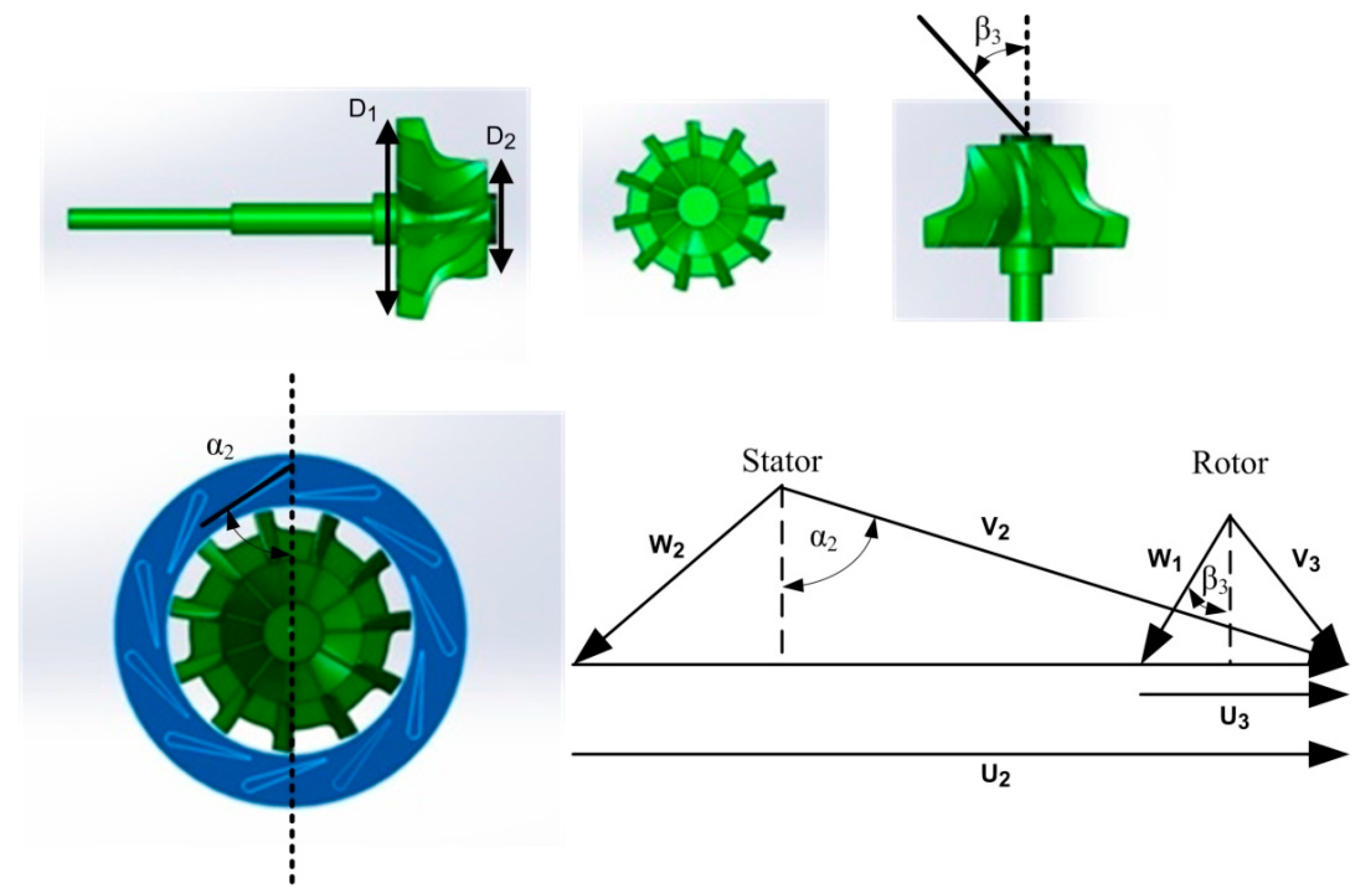
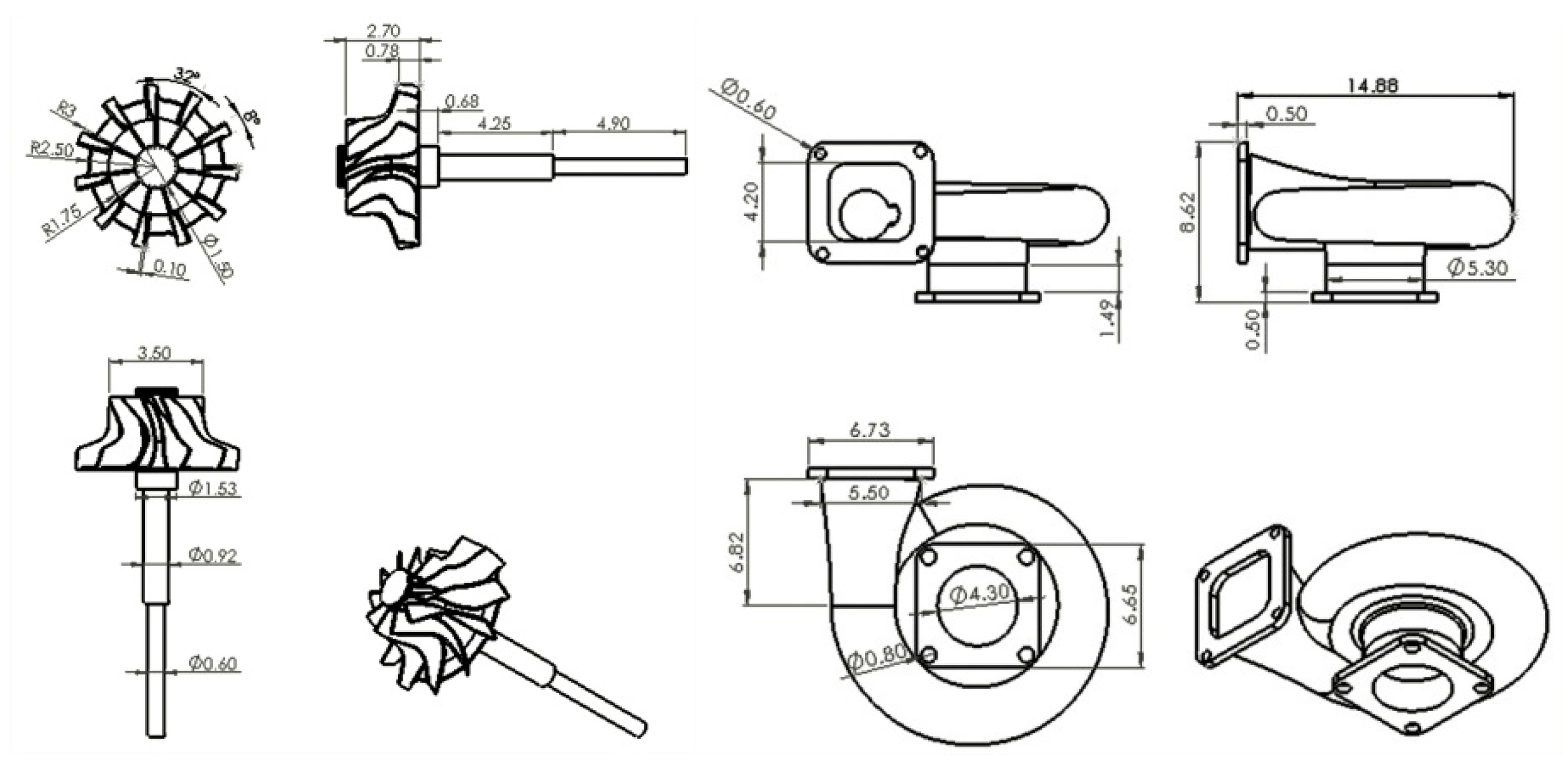
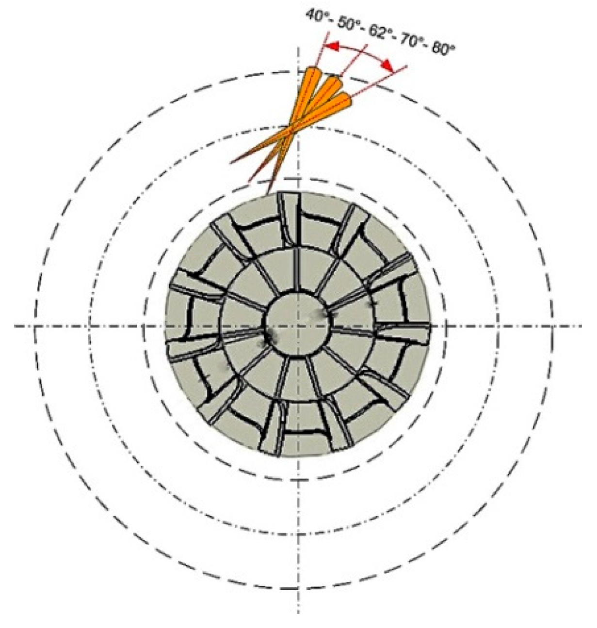
In the first step, the dimension design of the parts of the rotor used the details following the instructions as shown in Table 3 and Figure 3.
The equation below describes the relationships of the theoretical work for turbines:
L 0 = k 1 k 1 1 × R s p × T s × [ 1 ( P s P s ) k 1 1 k 1 ] ,
T s T s = ( P s P s ) K 1 1 K 1 ,
L o = k 1 k 1 1 × R s p × ( T s T s ) ,
where L 0 is the theoretical work by energy per mass of exhaust gas ( k J / k g ) , k 1 is the value of adiabatic exhaust gases, R s p is the constant value of the exhaust gases relative to the gas constant to the molecular weight of the gas, P s is the pressure of exhaust gases behind the turbine, P s is the pressure of exhaust gases in front of the turbine, T s is the temperature of exhaust gases flowing into the turbine, and T s is the temperature of exhaust gases flowing out from the turbine.
The following equation explains the size of the work occurring in the turbine, which is related to the decrease of the temperature after the exhaust gas flows through the turbine.
N t = G s × l t = G s × l 0 × η t ,
where N t is the theoretical power ( W ) , G s is the intensity of exhaust gas flow ( k g / s ) , and η t is the efficiency of the turbine in isentropic.
The Euler equation shows the energy transfer in the rotor, which can be represented as a product of the torque by the angular velocity:
W ˙ = ω ¯ T Q = m ˙ ( u 1 c 01 u 2 c 02 ) = m ˙ . c p ( T 10 T 20 ) ,
where W ˙ is the energy transfer, Q is the heat transfer per unit mass flow, ω ¯ is the angular velocity, m ˙ is the mass rate of flow, ( u 1 c 01 u 2 c 02 ) is the rate of change of angular momentum, c p is the specific heat at a constant pressure, and ( T 10 T 20 ) 10-T20 is the temperature difference of the inlet and outlet.

3.4. Formula for One Dimensional Calculation

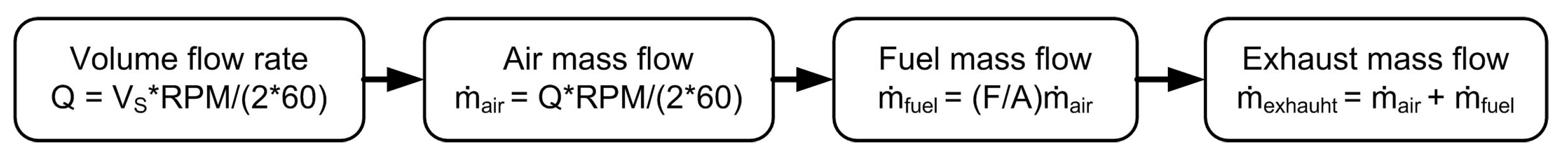
Once the energy transfer has been determined, the mass flow of exhaust gas required to achieve the specified power can be calculated from:
W = P o w e r m ˙ e x h a u s t .
The blade speed at the inlet can be calculated from the velocity triangles, in which the relative work output is:
u 2 = w .
The absolute velocity at the inlet:
v 2 = u 2 sin α 2 .
where α 2 is absolute gas angle at radius.
The radius at the inlet of the rotor has the value of:
r 2 = 60 u 2 2 π × r p m .
The relative velocity at the inlet:
w 2 = v 2 2 u 2 2 .
The rotor shroud radius and hub radius are:
r 3 s = 0.75 r 2 .
The rotor hub radius:
r 3 h = k r 3 s .
where k is the hub-tip ratio at the inlet impeller.
The hub blade speed:
u 3 h = 2 π r 3 h r p m 60 .
The shroud blade speed:
u 3 s = 2 π r 3 s r p m 60 .
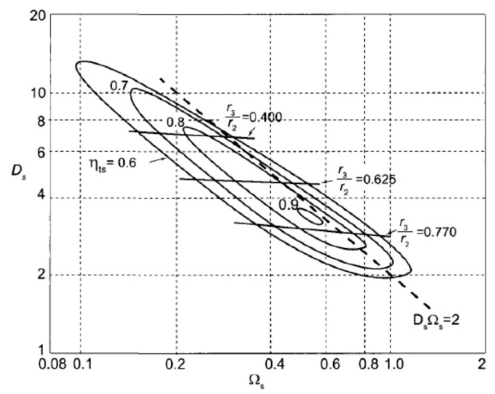
The mean of the exit radius is equal to its square value using the Balje diagram:
r 3 = 0.5 ( r 3 s 2 + r 3 h 2 ) .
Figure 4 shows the Balje diagram used to calculate the value of the exit radius. The value of Ω s efficiency is in range 0.2–0.8 and the recommended value of r 3 r 2 is in range 0.53–0.66.
Consequently, the blade speed at the mean exit radius is:
u 3 = 2 π r 3 r p m 60 .
The blade width at the outlet:
b 3 = r 3 s r 3 h .
Using mass balance, the inlet blade height can be determined as:
b 2 = m ˙ e x h a u s t 2 π r 2 v 2 cos α 2 .
Using the velocity diagram for calculating the flow angle of relative velocity at the exit:
β 3 = tan 1 ( u 3 v 3 ) .
The flow angle of relative velocity at the hub and shroud at the outlet are:
β 3 h = tan 1 ( u 3 h v 3 ) , β 3 s = tan 1 ( u 3 s v 3 ) .
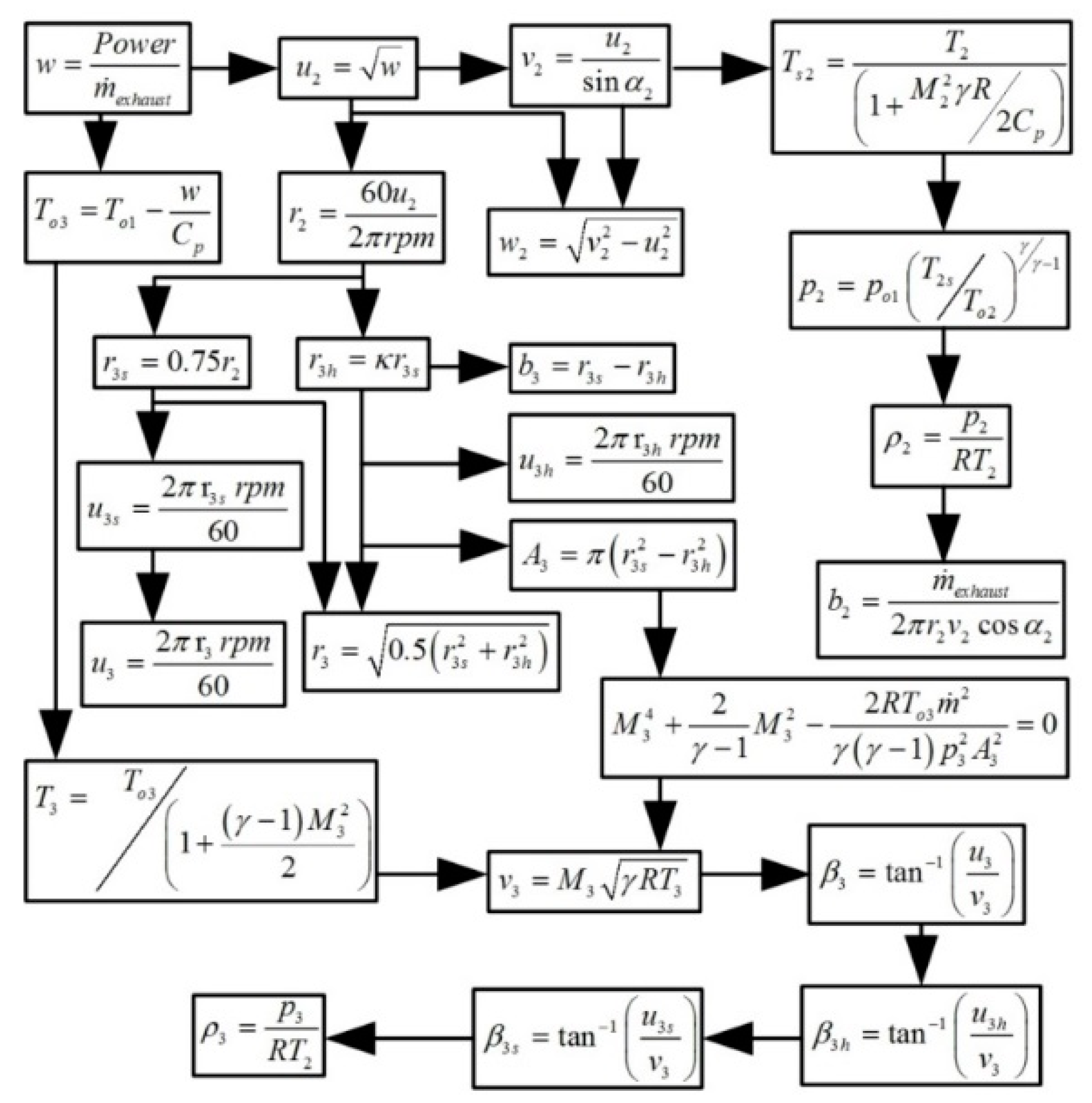
Figure 5 shows an overview of the equations used for calculating the dimensions of the turbine, respectively, where the process for calculating values is continuously correlated using the MATLAB program.

3.5. The Dimension Design

The values of the calculated components from the previous sections are summarized and shown in Table 4 in order to create the turbine model as well as applying the values for the turbo-generator drawing.

3.6. Drawing the Turbo-Generator

The turbo-generator parts use calculated values from Table 3 for drawing in Computer Aided Design (CAD) models of the rotor and volute with the size and shape shown in Figure 6. The overview of all parts is shown in Figure 7.
Part of the turbo-generator model:
The size of the new turbine design is shown in Table 5, and compared with the turbine of current vehicles. The differences of dimension occur when the inlet blade angle increases and the outlet blade angle decreases.

3.7. Drawing and Construction of a Thermoelectric Generator

The output voltage is directly proportional to the temperature change, which is the principle of a thermoelectric generator using the phenomenon characteristics known as the Seebeck effect [16], and displayed as the following equation:
V = α Δ T ,
where α is the Seebeck coefficient ( V K 1 ) and Δ T is the temperature difference of two sides of the surface in K .
The Reynolds number derived from the value of the heat source from the engine exhaust gas is:
R e = ρ v D / μ ,
where ρ is the density, ν is viscosity, D is the equivalent diameter, and μ is the viscosity of the fluid flowing through the tube.
The heat transfer coefficient of the hot side is determined by:
h e = N u k e / D h .
The Nusselt number is defined as the ratio of convection heat transfer to fluid conduction heat.
N u = h e D h k e ,
where N u is Nusselt number, k e is thermo conductivity of exhaust, and D h is the hydraulic diameter.
The following equation shows convection on the plate:
N u = 0.664 ( Re 0.5 × Pr 0.33 ) ,
where Re is the Reynolds number and Pr is the Prandtl number.
The heat conversion efficiency of waste heat recovery is calculated using the energy from the thermoelectric generator divided by the heat inserted into the thermoelectric generator.
η = P o u t p u t m ˙ C p ( T i n T o u t ) ,
where η is the conversion efficiency, P o u t p u t is the thermoelectric generator power output, m ˙ is the exhaust gas mass flow rate, C p is the exhaust gas specific heat, T i n is the exhaust gas system inlet temperature, and T o u t is the exhaust gas system outlet temperature.
The equation to calculating the power generated by the thermoelectric generator is:
P = N α p n I Δ T l e g I 2 N R p n ,
where N is the number of thermoelectric couples employed, α p n is the Seebeck coefficient, I is, respectively, the electric current, Δ T l e g is the thermoelectric leg temperature difference, and R p n is the value of the thermoelectric resistivity couple.
The equation for the system efficiency, η, can be calculated by:
η = p T E G P e n g i n e × 100 % ,
where p T E G is the thermoelectric generator maximum output power and P e n g i n e is the power of the engine.
The efficiency of a TE module used as a generator can be approximated by the following relationship, where Z is a material property, T c is cold temperature, T h is hot temperature, and T is ( T h + T c ) / 2 .
η T E max = W e l e c Q h = Δ T T h . 1 + Z T 1 1 + Z T + T c T h ,
Z = ( α p α n ) 2 ( ( λ p ρ p ) 1 / 2 + ( λ n ρ n ) 1 / 2 ) 2   ,
where α p is the Seebeck coefficient corresponding to p , α n is the Seebeck coefficient corresponding to n , λ p is thermal conductivity corresponding to p , λ n is thermal conductivity corresponding to n , ρ p is electrical resistivity the corresponding to p , and ρ n is electrical resistivity corresponding to n .
The power output is:
P = Q h Q c = I 2 R L ,
where I is the electrical current in the generator circuit, R L is the electric resistance of semiconductor couple, Q h is the heat absorbed from heat source, and Q c is the heat absorbed from the cold source.
Power outputs and conversion efficiencies were calculated applying the numerical results, the electric current and absorbed heat shown in the equations below:
P = N [ α p n ( T h T c ) I I 2 R ] ,
R = L A ( ρ n + ρ p ) ,  
η = P Q h ,
where P is the output power, N is the number of thermoelectric elements in the module, and α p n is the Seebeck coefficient. L is the length of the legs and A is the cross-sectional area.
The equation for the thermocouple conversion efficiency is:
η = P / Q h ,
where Q h is the absorbed and P is the output power.
Another important part of the process for designing a thermo-electric generator is finding the heat transfer correlations, which is calculated from the heat of the engine exhaust flowing through the exhaust pipe. The design will focus on the suitability and ease of installation with real engines in a limited space to make the best heat transfer efficiency and to not extremely affect the pressure of the exhaust. 
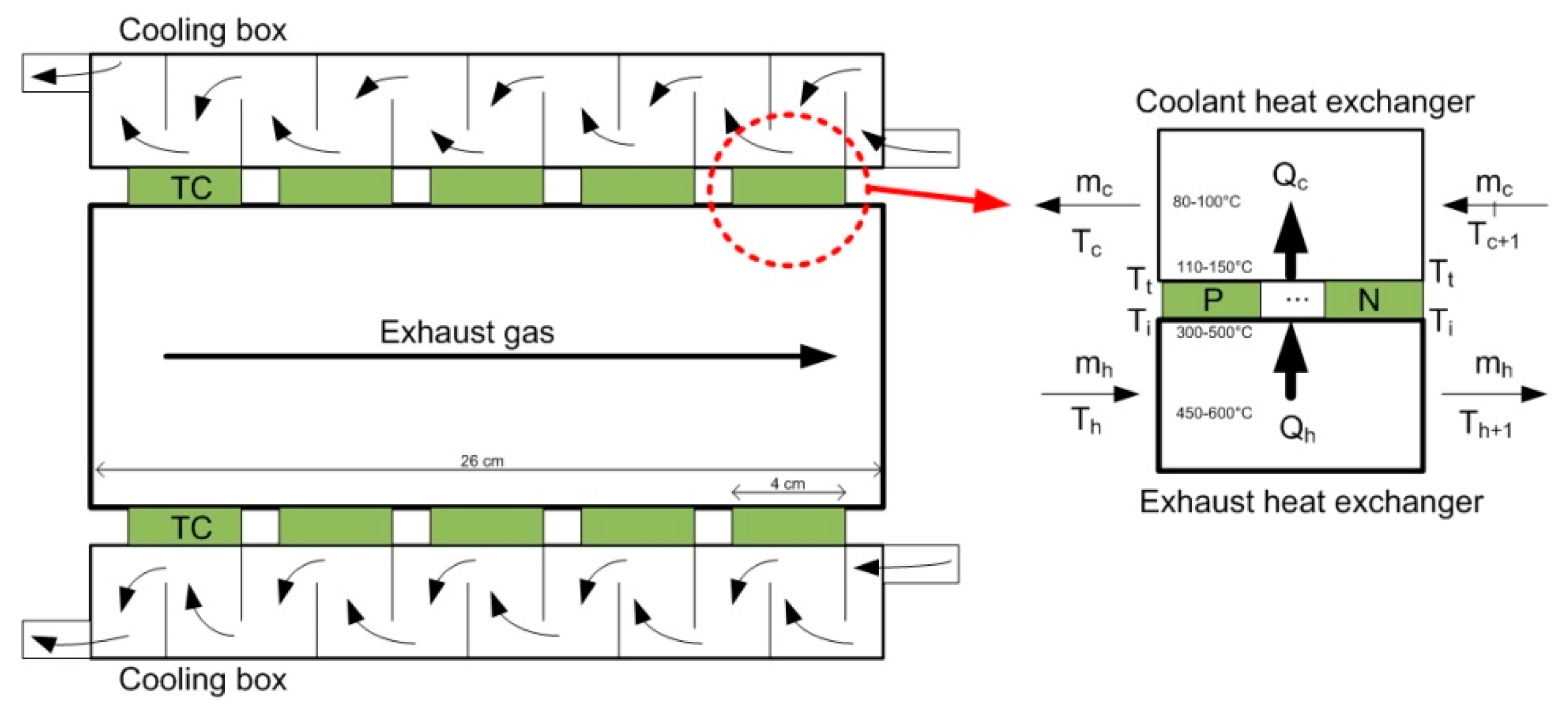
Figure 8 illustrates the heat transfer correlations of the thermo-electric generator.
Energy balance of cooling heat exchanger calculated by:
Q c = m c c p ( T c + 1 T c ) ,
Q c = h c A c ( T c ( T c + T c + 1 ) / 2 ) ,
where h c is the heat transfer coefficient for the coolant heat exchanger, A c is the heat transfer area for the coolant side, m c is the mass flow rate, T c is the coolant water temperature, and T t is the temperature of the cold side of the thermoelectric module.
Energy balance of exhaust heat exchanger calculated by:
Q h = m h c p ( T h T h + 1 ) ,
Q h = h h A h ( T h ( T h + T h + 1 ) / 2 T i ) ,
where h h is the heat transfer coefficient for the exhaust heat exchanger, A h is the heat transfer area for the exhaust side, m h is the mass flow rate, c p is the specific heat of the exhaust, T h is the temperature of the exhaust, and T i is the temperature of the hot side of the thermoelectric module.
Heat and cooling transfer of the system calculated by:
Q c = S I T c + K ( T h T c ) 0.5 I 2 R ,
Q h = S I T h + K ( T h T c ) 0.5 I 2 R ,
where S is the Seebeck coefficient, R is the internal resistance, K is the thermal conductance of the module, and I is the total current of the generator.
Calculations for efficiency of a thermo-electric generator:
The exhaust gas mass flow rate was 0.1024 kg/s, the exhaust gas specific heat c p g was 1 k J / k g . k , and the supplied heat was: t h e   e x h a u s t   g a s = m g c p g Δ T = 0.1024 × 1.148 × ( 110 115 ) = 587.776   W , e l e c t r i c a l   p o w e r   o u t p u t = V I = 16 × 5 = 80   W
e f f i c i e n c y   o f   t h e r m o e l e c t r i c   generator = e l e c t r i c a l   p o w e r   o u t p u t h e a t   sup p l i e d   b y   t h e   e x h a u s t   g a s = 13.61
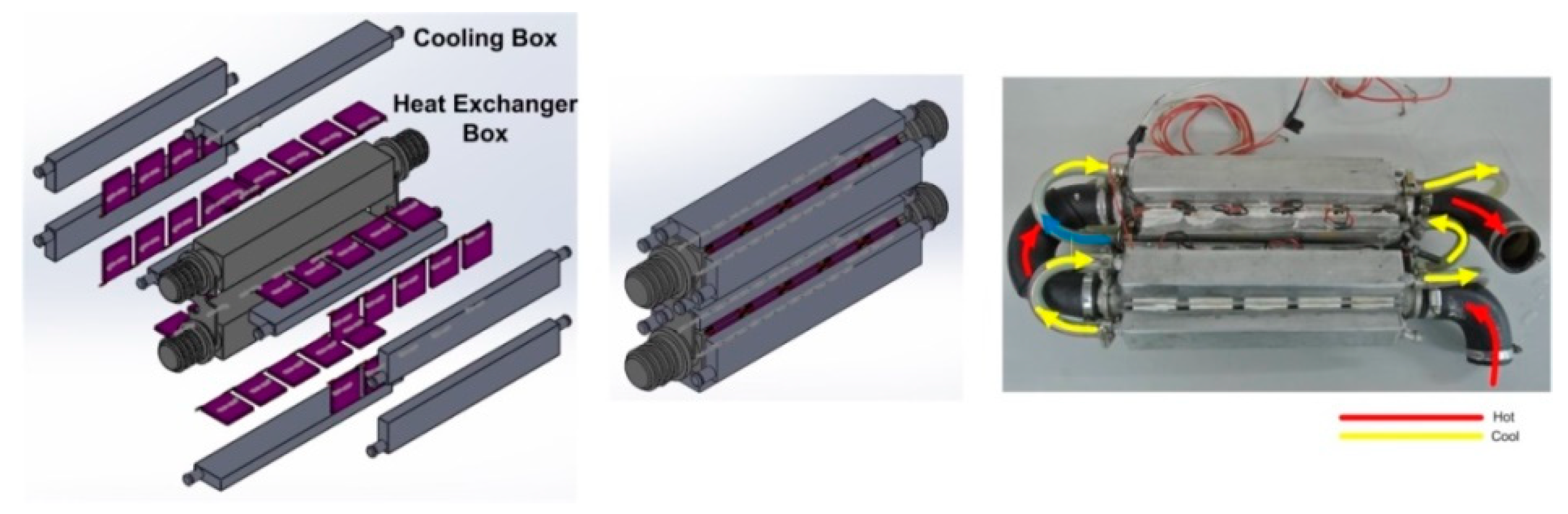
The thermoelectric module in Figure 9 composed of two units with dimensions of 240 mm × 100 mm × 300 mm. It is a combination of three main parts: The water cooling box, heat exchange box, and thermoelectric plate ( T E C I 12706 ) . The water cooling box has eight parts with dimensions of 70 mm × 40 mm × 300 mm. It was used as a thermo-electric plate to reduce the heat by removing the heat from the water using the radiator. The heat exchange box has dimensions of 100 mm × 100 mm × 300 mm to transfer the heat from hot water to the 80 thermoelectric plates. The design will focus on the suitability and ease of installation with real engines in limited space to make the best heat transfer efficiency and to not extremely affect the pressure of exhaust.

4. Simulation Results and Optimization

4.1. Turbine Performance

The steps of the CFD simulation started from design and drawing, which was shown in Figure 10 by modeling the adjustment of the vane angle at 40°, 50°, 62°, 80°, and 85° respectively. Then, the step was the model preparation for using in the simulation process. The step started from the CFX-Design Modeler procedure which is an important step of ANSYS simulation. The total number of faces that resulted from this procedure was 358 faces, separated into turbine 282 faces, exhaust gas 28 faces, and vane 48 faces. After that was the surface preparation procedure using the section of the CFX-Meshing. The total value of the model was 914,018 nodes and 3,461,517 elements, divided into turbine 509,734 nodes and 2,545,575 elements, exhaust gas 132,988 nodes and 688,147 elements and vane 271,296 nodes and 227,768 elements.
The next step was the process of simulating the flow condition in the model. The simulation simulated the exhaust flow that flowing into the inlet of the turbine case and simulated the flow out of the front. There are various configurations in this step including the exhaust flow rate, pressure temperature, and flow characteristics details as follows: The CFX-Pre procedure had three domains and three interfaces, the exhaust domain had a static inlet, an inlet mass flow rate 0.1024 kg/s, and outlet pressure at 101.325 kPa. Turbine domain configured a rotation speed between 15,000 and 35,000 rpm and the vane domain was defined as the static flow at 400 °C as shown in Figure 11.
The results of the simulation shown in Figure 12. In the simulation, there were eight different vane angle simulations including not vane, vane angle 40°, 50°, 62°, 80°, and 85°, and commercial 1, 2. The simulation was set with a rotation speed from 15,000 to 35,000 rpm.
The torque on the turbo blade was 0.628 N – m. This was used to calculate the power, using this equation:
P = T × 2 × π × N 60 = 0.628 × 2 × π × 52000 60 = 3401   watt .
Table 6 shows the comparison of torque and power for adjusting the inlet blade at various angles without the vane and commercial turbines.
The results of the simulation for the input parameter exhaust inlet was 0.1024 kg/s (3500 rpm; engine rotation speed), for the pressure outlet was 1.1 bars, and for the temperature was 400 °C. The inlet angle set to five variables with a vane angle of 40°, 50°, 62°, 70°, and 80° as shown in Figure 13. The results shown in Table 5 and Figure 14A suggest torque and power increased if the rotation speed increased. The turbine could generate from 1937 watts of power with an engine speed of 4200 rpm, when the vane angle varied from 40° (1937 watts) to 62° (3401 watts). After the vane angle increased to more than 62°, a reduction of power occurred.
The results from the simulation of the relationship between the generated power and rotation speed are shown in Figure 14B, the power output increased to 3401 watts at 25,000 rpm.

4.2. Pressure and Path Line of Flowing

The value of the pressure is shown in Figure 15. Pressure reached the maximum at the inlet and was lower at the outlet. The value at the inlet was 1.67 atm, at the volute was 1.46 atm, at the turbine blade was 1.20 atm, and at the outlet was 1 atm.
The value of the pressure was varied as shown in Figure 16. The highest pressure was 1.5 atm and the lowest at 1 atm. Pressure in the turbine blade in Figure 17 shows the characteristic of the exhaust gas flow in the gap between the rotor and volute, expressed as a flowing line from the entrance through the rotor blade and flowed out in front of the rotor.
The sound speed at the turbine blade was 490–530 m/s. This sound speed was an acceptable value for the shock wave design as shown in Figure 18.

5. Experimental Results

5.1. Experimental Setup

The experimental facility shown in Figure 19 used in this study was based on a real internal combustion engine, and experiment testing works without load. The experimental design for the experiment consists of four main parts: The engine building, turbo-generator unit, thermoelectric-generator unit, and parameter output measurement. The engine was based on a 2500 cc. diesel engine (Toyota 2LII model). The engine consisted of a water-cooling system, oil lubricating system, and engine electric system. The turbo-generator consisted of a turbine, volute, vane, and generator. The connection of the turbine to the generator used coupling and the gear reducer rotation speed. The thermoelectric-generator consisted of a water-cooling box, heat exchange box, and thermoelectric plate. Finally, the performance measurement aimed to find the engine rotating speed, turbo-generator rotating speed, temperature and pressure measurement, exhaust gas measurement, and finally the power measurement of the turbo-generator and thermoelectric-generator.
Each experiment performed 10 times with the same condition. The values from results recorded after the engine runs 20 min so that the engine was working in the heat condition. The speed of the engine was adjusted with step 100 rpm started from 1000 to 3600 rpm. The values recorded consisted of the engine rotation speed, inlet and outlet temperature of the turbo-generator, inlet and outlet temperature of the thermoelectric-generator, the power value from the turbo-generator, and the power value from the thermoelectric-generator.

5.2. The Measurement Intrument

The set of instruments for measuring values from the experiments were created specifically. The main components were divided into three parts: The processing and interpret sections, data recording section, and the measuring sensors detailed as follows:
The first section was the processing section using the STM32F407 microcontrollers for receiving the values from the sensor and displaying the values with the LCD monitor.
Since you have not mentioned about the details of this sensors/apparatus, so that in order to understand the reported results the measurement accuracy of the discussed
The second part was the section for receiving values from the microcontroller to store in the SD card. The SD card module recorded the values in two ways: When the value changed and recorded the values every second.
The third part was the sensor that sent various values in both the digital and analog signal to the microcontroller composing of the following values: Engine rotation speed, turbo generator rotation speed, inlet temperature of the turbo generator, outlet temperature of the turbo generator, inlet temperature of thermoelectric, outlet temperature of thermoelectric, inlet pressure of the turbo generator, outlet pressure of the turbo generator, output power turbo generator, and output power of thermoelectric. The details of the sensor used as following: Engine rotation speed and turbo generator rotation speed used the hall effect proximity switch (NJK-5002C), inlet temperature of the turbo generator, outlet temperature of the turbo generator, inlet temperature of thermoelectric, and outlet temperature of the thermoelectric used resistance temperature detector (PT100 RTD), inlet pressure of the turbo generator, and outlet pressure of the turbo generator used MEMS pressure sensor (XGZP701DB1R), output power turbo generator, and output power of thermoelectric used current detection sensor module (WCS1800).
These instruments are comparable to the standard instruments and adjusted to the precise value to solve the problem of variance of experimental results, as the results of each trial result, the value of the measurement instrument is different, but there will be a tendency or appearance of the same rise or decline. This causes different values due to a number of factors such as how long it takes to start an extended engine to heat up the inside of the engine, and the heat in the exhaust is more as well. The acceleration of the engine at each time of the trial is not fixed. Sometimes the speed of the cycle may be accelerated or sometimes slow acceleration. This affects the exhaust pressure and the heat of the exhaust, and the installation in experiments does not start at the same heat, can affect the various values that come out. Therefore, it uses multiple experiments to find the average value that makes the measured value more reliable. Before the actual experiments, the trial operator was experimented 20 times to make the actual experiment the most accurate. In conclusion, each test was made when the engine was at a normal temperature (before starting the engine). The values recorded starting from the operating temperature of the engine that was 80 degrees Celsius. The engine acceleration gradually accelerated from the light to the peak. In each trial, there was a time equivalent of 1 h. The experiment would repeat 20 times in each experiment and then select 10 times of experimental results with the lowest variance and maximum reliability. The selected variance with uncertainty between ± 0.1%–3.0%.

5.3. Temperature of the Exhaust Turbo-Generator

The temperature experiment on the turbo-generator was undertaken by running the engine and adjusting the engine idle speed to the maximum speed. The temperature sensor measurement was installed at the inlet and outlet of the turbo-generator as shown in Figure 20. The graph shows the correlation value between the rotation speed engine and exhaust gas temperature. The trial operation repeated 10 times for calculating the average value, as shown in the picture. The experiments consisted of measurements inlet and outlet exhaust gas temperature in the turbo-generator and recorded the values from the starting point of the engine (600 rpm) and accelerated the speed of the engine to the maximum speed (4700 rpm). The X-axis displays the engine rotation speed in rounds per minute (rpm). The Y-axis displays the exhaust gas temperature in degrees Celsius. The red line shows the outlet exhaust gas temperature and blue line shows the inlet exhaust gas temperature.
The temperature of the exhaust gas depends on the rotation speed of the engine and the engine running time. At the beginning of the rotation, the exhaust gas temperature was lower. It will increase as the speed of the engine increases, as a result of the heat combustion of exhaust gas. The inlet temperature was higher than the outlet temperature since the direct proportion characteristics.

5.4. Pressure of the Exhaust Turbo-Generator

Pressure measurements of the turbo-generator were taken by running the engine and adjusting the speed of the accelerator from idle speed to the maximum speed. The measurements were taken at the inlet and outlet of the turbo-generator as illustrated in Figure 21. The graph shows the correlation value between the rotation speed engine and exhaust gas pressure. The trial was operated 10 times for calculating the average value as shown in the picture. The experiments consisted of the measurements inlet and outlet exhaust gas pressure in the turbo-generator and recording the values from the starting point of the engine (600 rpm) and increase the speed of the engine to the maximum speed (4700 rpm). The X-axis displays the engine rotation speed in rounds per minute (rpm). The Y-axis displays the exhaust gas pressure in kilopascals. The red line shows the inlet exhaust gas pressure and the blue line shows the outlet exhaust gas pressure.
The rotation speed of the engine and runtime engine defines the pressure of the exhaust gases. During the initial stage, the rotation speed of the pressure was low. It will increase as the speed increases, as a result of the exhaust gas flow rate. The outlet pressure was lower than the inlet pressure.

5.5. Rotation Speed of the Turbo-Generator Test Based on a Variable Vane Angle

The rotational test of the rotation speed of the turbo-generator was undertaken by running the engine and adjusting the accelerator speed from idle to maximum speed, along with an adjustment of the vane angle testing set. The results are shown in Figure 18. The graphs show the correlation value between the rotation speed engine and the turbo-generator rotation speed with 10 times the repeat experiments for calculating the average value, as shown in the graph. The experiments measured the engine rotation speed in the pulley position of the engine, measured the turbo-generator rotation speed in the axis position of the turbo-generator and recorded the value from the starting point of the engine at a lighter speed (700 rpm), and then accelerated the engine speed to the maximum speed (3600 rpm). The X-axis shows the engine rotation speed in rpm. The Y-axis shows the turbo-generator rotation speed in the rpm. The red line shows a 52° vane angle turbo-generator rotation speed, the green line showing a 62° vane angle turbo-generator rotation speed, and the blue line displaying a 72° vane angle turbo-generator rotation speed.
Figure 22 shows three different conditions of the engine speed and vane angle. When the vane angle was 62°, speed increased at a stable rate and had a tendency to continuously increase. When the vane angle was 52°, the turbo-generator started to rotate at a high engine speed. When the vane angle was 72° the turbo-generator speed increased as the engine speed increased, and it tended to decrease at a higher engine speed. Increasing the number of vanes decreased the axial flow velocity and increased the turbulence energy [23].

5.6. Power of the Turbo-Generator Test Based on Adjusting the Vane Angle

The power test of the rotation speed of the turbo-generator was undertaken by running the engine and by adjusting the accelerator speed from idle speed to maximum speed. The vane angle was adjusted for each testing set as shown in Figure 19. The graphs display the correlation value between the rotation speed engine and the turbo-generator power by performing 10 iterations of the experiment and calculating the average value. The experiment consisted of measuring the engine rotation speed in the pulley position of the engine and the turbo-generator power in the axis of output power of turbo-generator. Then, the values recorded from the starting point of the engine at 700 rpm and accelerated the speed of the engine to the maximum speed (3600 rpm). The X-axis is a rotation speed engine in rpm. The Y-axis is the turbo-generator power in watts. The red line represents the 62° vane angle turbo-generator rotation power, the green line represents the 72° vane angle turbo-generator rotation power, and the blue line represents the 52° vane angle turbo-generator rotation power.
Figure 23 illustrates the correlation value of the engine rotation cycle with the capacity outputted from the turbo-generator with the angle adjustment of three vane levels. The total output of energy was increased when the cycle speed of the turbo-generator engine was increased with adjusting the angle of the vane at 62° and 72°. The engine could produce energy from the beginning at low speed up to the maximum speed while the turbo-generator adjusted the angle of the vane at 52° must be added to the engine rotation cycle to 2400 rpm to start producing power output. As shown in the graph, the turbo-generator with the vane at 62° had a capacity of producing the maximum energy starting from 150 watts at the engine rotation around 900 rpm and increased by rotation cycle to 900 watt at 3600 rpm.
Turbine efficiency:
η t = T 00 T 20 T 00 T 2 s = 51.1 % .
Total Shaft Output Power:
The reduction of turbo-generator energy can be divided into three speed of different power: Idle speed (145 watts), running speed (870 watts), and high speed (890 watts).

5.7. Power of the Thermoelectric-Generator Test

The power output from the thermoelectric generator shown in Figure 24. The graph shows the relationship value between the engine running time and the thermoelectric-generator output power, with 10 repeat experiments for calculating the average value. The experiments consist of measuring the engine running time when starting the engine and measuring the thermoelectric-generator output power in the power cord position. The values were recorded from the starting point of the engine at 700 rpm, and accelerated the speed of the engine to the maximum speed (3600 rpm). The X-axis is the engine running time, showing the value in seconds. The Y-axis is the thermoelectric-generator output power display value in watts. The red line is the inlet exhaust gas temperature, the yellow line is the outlet exhaust gas temperature, the green line is the output voltage, the purple line is the output current, and the blue line is the output power. The line-graph illustrates the exhaust temperature and power when running the engine. Overall, the power output is related to the temperature difference. To begin with, the power output started at 271 watts, before it increased to just under 392 watts at a higher temperature. This fell slightly when the engine was stopped, before dropping to its lowest point of 288 watts at the end of testing.
Figure 25 shows the correlation between the rotation speed of the engine and output power of the whole system. The trial operation was repeated 10 times for calculating the average value. The X-axis represents the engine rotation speed. The Y-axis represents the output power. The red line represents the energy from the turbo-generator. The green line represents the energy from the thermo-electric generator, and the blue line represents the total power from the turbo-generator and thermo-electric generator. The total power saving when combining both the turbo-generator and thermo-electric generator units was 1262 watts.

6. Conclusions

Turbo-generators and thermoelectric generators are ideal for the recovery of waste energy in exhaust gas. The temperature and flow pressure of the combustion engine is transformed into electric power. That power can be converted into electrical energy to support the electrical supply in a vehicle. Normally, exhaust gas is discarded to the environment as waste gas. The main difference between this research and previous works is the type of energy from exhaust gases for recycling. Most of previous works used either pressure or heat whilst this research focus on the discharge of energy from the exhaust with both pressure and heat recovery to the form of electrical energy. In addition, this research designed the prototype for a 2500 cubic centimeters diesel engine, which is widely used. The research aimed to design a turbo-generator and thermoelectric generator that could convert exhaust gas energy to electrical energy. The turbo-generator model could generate up to 870 watts of power at 3400 rpm (top speed of the engine), and the thermoelectric generator could generate up to 392 watts of power. Both systems combined could generate up to 1262 watts of power. The electric power can be used in electric charging; generally, the alternator will produce 12 volts, or 35 amperes (420 watts), to support in-vehicle usage. The experiments were a comparison of the results from the simulation from the design and optimization of the vane angle of 40°, 50°, 62°, 70°, and 80° with the results of the installation and the actual test. The result shows that everything was consistent in the design with the angle vane 62°. Besides that, in the simulation process, the result shows that the angle vane gave the maximum torque and power, which corresponded to the same direction as the outcome of the actual trial. The integrated turbo-generator and thermoelectric generator could potentially be used as part of the charging system. Energy recovery during driving can be used for battery charging and as an energy storage device. In this model, the turbo-generator and thermoelectric generator had the capacity to generate up to 1262 watts that could be utilized in hybrid vehicles. The power from the recovery of waste energy could support the electrical needs of other parts. At present, the device converts the power into electricity, and for the convenience of the driver, it could be utilized for features such as electric air conditioning, electric power steering, refrigerators, and mobile phone chargers.

Author Contributions

P.N. contributed to the conceptualization, methodology, validation, and data collection, and wrote the paper; M.E., U.N. and E.B. made corrections to the paper and gave some useful recommendations.

Funding

This research was funded by Asian Institute of Technology, School of Engineering and Technology, Thailand.

Acknowledgments

The authors would like to thank the Rajamangala University of Technology Srivijaya for scholarship in doctoral study.

Conflicts of Interest

No conflict of interest.

References

  1. Yang, J. Potential applications of thermoelectric waste heat recovery in the automotive industry. In Proceedings of the International Conference on Thermoelectrics, Clemson, SC, USA, 19–23 June 2005; pp. 155–159. [Google Scholar]
  2. Xiong, Y.; Xu, L.; Zhong, Y. The Theory and Application of Energy-Saving Technology on Vehicle; China Petrochemical Press: Beijing, China, 2006; pp. 9–13. [Google Scholar]
  3. Fu, J.; Liu, J.; Yang, Y.; Yang, H. A study on the prospect of engine exhaust gas energy recovery. In Proceedings of the International Conference on Electric Information and Control Engineering, Wuhan, China, 15–17 April 2011. [Google Scholar]
  4. Jorge, V. State of the Art of Thermoelectric Generators Based on Heat Recovered from the Exhaust Gases of Automobiles. In Proceedings of the 7th European Workshop on Thermoelectric, Pamplona, Spain, 3–4 October 2002. [Google Scholar]
  5. La Grandeur, J.; Doug Crane, D.; Eder, A. Vehicle Fuel Economy Improvement through Thermoelectric Waste Heat Recovery. In Proceedings of the 11th Diesel Engine Emissions Reduction (DEER) Conference, Chicago, IL, USA, 21–25 August 2005. [Google Scholar]
  6. Fairbanks, J. Overview of High Efficiency Thermoelectric and Potential Applications. In Proceedings of the High Efficiency Thermoelectric Workshop, San Diego, CA, USA, 17–20 February 2004. [Google Scholar]
  7. Michon, M. Switched Reluctance Turbo-Generator for Exhaust Gas Energy Recovery. In Proceedings of the International Conference on Electric Machines & Drives Conference (IEMDC), Niagara Falls, ON, Canada, 15–18 May 2011; pp. 1609–1614. [Google Scholar]
  8. Aman Mamat, M.I. Design and Development of a Low Pressure Turbine for Turbocompounding Applications. Int. J. Gas Turbine Propuls. Power Syst. 2012, 4, 1–8. [Google Scholar]
  9. Hopmann, U.; Algrain, M.C. Diesel Engine Electric Turbo Compound Technology. In Proceedings of the Future Transportation Technology Conference & Exhibition; SAE International: Warrendale, PA, USA, 2003. [Google Scholar] [CrossRef]
  10. Hopmann, U. Diesel engine waste heat recovery utilizing electric turbocompound technology. In Proceedings of the Catterpillar, DEER Conference, San Diego, CA, USA, 30 August–2 September 2004. [Google Scholar]
  11. Hopmann, U.; Algrain, M. Diesel engine waste heat recovery utilizing electric turbocompound technology. Presented at the 2003 DEER Conference, Newport, Rhode Island, 25–28 August 2003; Caterpillar Inc.: Deerfield, IL, USA, 2003. [Google Scholar]
  12. Bowman Power Group Ltd. Available online: http://www.bowmanpower.com/power_generators.php (accessed on 20 August 2017).
  13. Controlled Power Technologies Limited. Available online: http://www.cpowert.com/products/tigers/ (accessed on 20 August 2017).
  14. Srinivasan, K.K.; Mago, P.J.; Krishnan, S.R. Analysis of exhaust waste heat recovery from a dual fuel low temperature combustion engine using an Organic Rankine Cycle. Energy 2010, 35, 2387–2399. [Google Scholar] [CrossRef]
  15. Yamada, N.; Minami, T.; Mohamad, M.N. Fundamental experiment of pumpless Rankine-type cycle for low-temperature heat recovery. Energy 2011, 36, 1010–1017. [Google Scholar] [CrossRef]
  16. Liu, X.; Deng, Y.D.; Chen, S.; Wang, W.S.; Xu, Y.; Su, C.Q. A case study on compatibility of automotive exhaust thermoelectric generation system, catalytic converter and muffler. Case Stud. Therm. Eng. 2014, 2, 62–66. [Google Scholar] [CrossRef] [Green Version]
  17. Kim, T.Y.; Negash, A.A.; Cho, G. Waste heat recovery of a diesel engine using a thermoelectric generator equipped with customized thermoelectric modules. Energy Convers. Manag. 2016, 124, 280–286. [Google Scholar] [CrossRef]
  18. Liang, X.; Sun, X.; Tian, H.; Shu, G.; Wang, Y.; Wang, X. Comparison and parameter optimization of a two-stage thermoelectric generator using high temperature exhaust of internal combustion engine. Appl. Energy 2014, 130, 190–199. [Google Scholar] [CrossRef]
  19. Tian, H.; Sun, X.; Jia, Q.; Liang, X.; Shu, G.; Wang, X. Comparison and parameter optimization of a segmented thermoelectric generator by using the high temperature exhaust of a diesel engine. Energy 2015, 84, 121–130. [Google Scholar] [CrossRef]
  20. Temizer, İ.; İlkılı, C. The performance and analysis of the thermoelectric generator system used in diesel engines. Renew. Sustain. Energy Rev. 2016, 63, 141–151. [Google Scholar] [CrossRef]
  21. Liu, C.; Pan, X.; Zheng, X.; Yan, Y.; Li, W. An experimental study of a novel prototype for two-stage thermoelectric generator from vehicle exhaust. J. Energy Inst. 2016, 89, 271–281. [Google Scholar] [CrossRef]
  22. Seppo, A. Principles of Turbomachinery; John Wiley & Sons: New York, NY, USA, 2011. [Google Scholar]
  23. Luft, M.; Olszowiec, P. Losses of IC engine—A chance for electrical energy recuperation. Zesz. Nauk. Akad. Morska Szczec. 2012, 30, 78–82. [Google Scholar]
Figure 1. Exhaust energy
Energies 12 03134 g001
Figure 2. Exhaust gas.
Energies 12 03134 g002
Figure 3. Velocity triangles for the rotor and stator.
Energies 12 03134 g003
Figure 4. Balje diagram for a radial turbine [Reproduced with permission from [22], Seppo, A. Principles of Turbomachinery; John Wiley & Sons: New York, NY, USA, 2011.].
Energies 12 03134 g004
Figure 5. The dimension design of turbine.
Energies 12 03134 g005
Figure 6. Rotor and volute design.
Energies 12 03134 g006
Figure 7. The turbo-generator components.
Energies 12 03134 g007
Figure 8. Heat transfer correlation of the thermoelectric module.
Energies 12 03134 g008
Figure 9. Thermoelectric generator module.
Energies 12 03134 g009
Figure 10. Model preparation. (A) CFX-design modeler and (B) CFX-meshing.
Energies 12 03134 g010
Figure 11. CFX-pre simulation.
Energies 12 03134 g011
Figure 12. Moment on the turbine.
Energies 12 03134 g012
Figure 13. The variable vane angled; 40°, 50°, 62°, 80°, and 85°.
Energies 12 03134 g013
Figure 14. Generated power results. (A) Results showing the vane angle and power and (B) results showing the rotation speed and power.
Energies 12 03134 g014
Figure 15. Pressure at all turbine walls.
Energies 12 03134 g015
Figure 16. Pressure at the turbine blade.
Energies 12 03134 g016
Figure 17. Path line of flowing at the turbine blade.
Energies 12 03134 g017
Figure 18. Sound speed at the turbine blade.
Energies 12 03134 g018
Figure 19. The real internal combustion engine test.
Energies 12 03134 g019
Figure 20. The inlet and outlet exhaust temperature.
Energies 12 03134 g020
Figure 21. Inlet and outlet exhaust pressure.
Energies 12 03134 g021
Figure 22. Rotation speed of the turbo-generator test.
Energies 12 03134 g022
Figure 23. Power of the turbo-generator test.
Energies 12 03134 g023
Figure 24. Power of the thermoelectric-generator test.
Energies 12 03134 g024
Figure 25. Total output power.
Energies 12 03134 g025
Table 1. Summary of parameters for turbo-generators and the thermoelectric generator model.
EngineMobileTypeEnergy ReceiveSpeedWeigh ExtraReference
n/aYes (Heavy-Duty)TG600 W45,000 rpm11 kg[11]
n/an/aTG1.8 kW80,000 rpmn/a[12]
DieselNo (Power Plant)TG30 kW60,000 rpm50 kg[13]
Gasoline 1.0 LYes (Passenger)TG1.0 kW50,000 rpmn/a[14]
DieselYes (Heavy-Duty)TEG119 Wn/an/a[18]
DieselYesTEG156.7 Wn/an/a[21]
DieselNo (Power Plant)TEG250Wn/an/a[22]
Diesel 2.5 LYes (Light-Truck)TG + TEG1262 W50,000 rpm15 kgAuthor work
TG (turbo-generator), TEG (thermoelectric-generator), and n/a (not available).
Table 2. Mass and velocity flow of exhaust gas on difference engine rotation speed.
Engine Rotation Speed (rpm)Exhaust Gas Mass Flow Rate (kg/sec)Exhaust Gas Flow Velocity (m/min)
10000.0320900
20000.06401799
30000.09602699
32000.10243598
40000.12803778
50000.16004498
Table 3. Design parameters of the rotor.
ParameterRecommended RangeSource
α 2 68–75Dixon, Rohlik
β 3 50–70Whitfiel and Baines
D 3 H / D 3 S <0.4Dixon, Rohlik
D 3 S / D 2 <0.7Dixon, Rohlik
D 3 / D 2 0.53–0.66Whitfiel and Baines
b 2 / D 2 0.05–0.15Whitfiel and Baines, Dixon, Rohlik
U 2 / C 0 0.55–0.80Balje diagram
W 3 / W 2 2–2.5Ribaud and Mischell
V 3 / V 2 0.15–0.5Whitfiel and Baines
Table 4. The results from the one-dimensional calculation of the radial turbine.
NoDescriptionAbbreviationUnitValue
1The flow angle at inlet of impeller α 2   degree   62
2The radius at inlet r 2   m   0.0298
3The inlet blade height b 2   m   0.0076
4The rotor shroud radius r 3 s   m   0.0175
5The rotor hub radius r 3 h   m   0.0075
6The mean exit radius r 3   m   0.0134
7The flow angle of relative velocity at outlet β 3   degree   17.4907
8The flow angle of relative velocity at shroud β 3 s   degree   22.2716
9The flow angle of relative velocity at hub β 3 h   degree   9.9650
10The blade width at outlet b 3   m   0.01
Table 5. The geometric features of the turbine compared with turbines in current commercial cars.
TurbineNew Design RotorCommercial Rotor1/2 *
Number of blades1111
Inlet blade angle62°20°/30°
Outlet blade angle17°50°/60°
Turbine diameter (mm)6060
Vane angleVaried 62°No vane
Rotation speed (rpm)52,000
Mass flow rate (kg/s)0.1024
Temperature inlet/outlet (°C)400/80
Pressure outlet (bar)1.1
* Toyota Hilux model.
Table 6. Turbine performance.
None40°50°62°70°80°Commercial 1Commercial 2
Torque0.1380.3550.5250.6240.5780.5020.2590.289
Power7521937285834013147273414111573

